EP3127215B1 - Foreign object detection by a wireless power transmitter - Google Patents
Foreign object detection by a wireless power transmitter Download PDFInfo
- Publication number
- EP3127215B1 EP3127215B1 EP15774155.4A EP15774155A EP3127215B1 EP 3127215 B1 EP3127215 B1 EP 3127215B1 EP 15774155 A EP15774155 A EP 15774155A EP 3127215 B1 EP3127215 B1 EP 3127215B1
- Authority
- EP
- European Patent Office
- Prior art keywords
- wireless power
- ringing
- threshold
- power transmitter
- foreign object
- Prior art date
- Legal status (The legal status is an assumption and is not a legal conclusion. Google has not performed a legal analysis and makes no representation as to the accuracy of the status listed.)
- Active
Links
Images


Classifications
-
- H—ELECTRICITY
- H02—GENERATION; CONVERSION OR DISTRIBUTION OF ELECTRIC POWER
- H02J—ELECTRIC POWER NETWORKS; CIRCUIT ARRANGEMENTS OR SYSTEMS FOR SUPPLYING OR DISTRIBUTING ELECTRIC POWER; SYSTEMS FOR STORING ELECTRIC ENERGY
- H02J50/00—Circuit arrangements or systems for wireless supply or distribution of electric power
- H02J50/60—Circuit arrangements or systems for wireless supply or distribution of electric power responsive to the presence of foreign objects, e.g. detection of living beings
-
- H—ELECTRICITY
- H02—GENERATION; CONVERSION OR DISTRIBUTION OF ELECTRIC POWER
- H02J—ELECTRIC POWER NETWORKS; CIRCUIT ARRANGEMENTS OR SYSTEMS FOR SUPPLYING OR DISTRIBUTING ELECTRIC POWER; SYSTEMS FOR STORING ELECTRIC ENERGY
- H02J50/00—Circuit arrangements or systems for wireless supply or distribution of electric power
- H02J50/10—Circuit arrangements or systems for wireless supply or distribution of electric power using inductive coupling
- H02J50/12—Circuit arrangements or systems for wireless supply or distribution of electric power using inductive coupling of the resonant type
-
- H—ELECTRICITY
- H02—GENERATION; CONVERSION OR DISTRIBUTION OF ELECTRIC POWER
- H02J—ELECTRIC POWER NETWORKS; CIRCUIT ARRANGEMENTS OR SYSTEMS FOR SUPPLYING OR DISTRIBUTING ELECTRIC POWER; SYSTEMS FOR STORING ELECTRIC ENERGY
- H02J50/00—Circuit arrangements or systems for wireless supply or distribution of electric power
- H02J50/70—Circuit arrangements or systems for wireless supply or distribution of electric power involving the reduction of electric, magnetic or electromagnetic leakage fields
-
- H—ELECTRICITY
- H02—GENERATION; CONVERSION OR DISTRIBUTION OF ELECTRIC POWER
- H02J—ELECTRIC POWER NETWORKS; CIRCUIT ARRANGEMENTS OR SYSTEMS FOR SUPPLYING OR DISTRIBUTING ELECTRIC POWER; SYSTEMS FOR STORING ELECTRIC ENERGY
- H02J7/00—Circuit arrangements for charging or discharging batteries or for supplying loads from batteries
- H02J7/70—Circuit arrangements for charging or discharging batteries or for supplying loads from batteries characterised by the mechanical construction
Definitions
- Wireless power is becoming increasingly popular for transferring energy to a device, such as to charge a battery in the device, and to do so without having to plug the device into a power source.
- Power is transferred through the inductive coupling of a magnetic field generated by a transmitter and delivered wirelessly to a receiver, such as in a battery-operated device.
- a pair of coils of wire are useful to wirelessly transfer the energy from transmitter to receiver.
- Charging pads are available, which employ this technology.
- a battery-operated device such as a smart phone
- a battery-operated device such as a smart phone
- a concern with wireless power transfer systems is the heating of metallic objects, which may be unintentionally exposed to the magnetic field.
- a coin, candy wrapper or car keys inadvertently might be placed on the charging pad along with the smart phone to be charged. If such objects are metal, they may absorb the energy that is wirelessly transmitted and intended for the phone. As a result, the metal object warms up. The worst possible place for such an object is between the phone and the charging pad.
- a metal object in that location may be heated to temperatures that can melt the plastic surfaces of the phone and the charging pad and pose a risk of fire.
- WO 2013/164831 relates to a system and method for triggering power transfer across an inductive power coupling and non resonant transmission.
- a wireless power transmitter includes an analog-to-digital converter (ADC) and a controller.
- the ADC is configured to convert an analog signal associated with a power train to digital values.
- the controller is configured to: cause pulses to be applied to the power train to thereby cause the power train to ring after the pulses are completed; receive digital values from the ADC acquired while the power train is ringing; and, based on an analysis of the digital values of the ringing of the power train, determine whether a wireless power receiver is present on or near a charging pad or whether a foreign object is present on the charging pad.
- a wireless power transmitter in another example, includes an analog-to-digital converter (ADC) and a controller.
- the ADC is configured to convert an analog signal associated with a power train to digital values.
- the controller is configured to cause pulses to be applied to the power train to thereby cause the power train to ring at a resonant frequency and to receive digital values from the ADC acquired while the power train is ringing and after the pulses are completed.
- the digital values are indicative of the ringing.
- the controller further is configured to compute a value indicative of a duration of the ringing, a decay rate of the ringing, and a peak amplitude at a beginning of a ringing period.
- the controller is configured to determine that no wireless power receiver nor foreign object is present on or near the wireless power transmitter if the value indicative of the duration of the ringing is greater than an empty wireless power transmitter duration threshold.
- the controller is configured to determine that a foreign object is present on or near the wireless power transmitter if the value indicative of the duration is less than the empty wireless power transmitter duration threshold, the decay rate is greater than a decay rate threshold, and the peak amplitude is greater than a peak amplitude threshold. Further, the controller is configured to determine that a wireless power receiver is present on or near the wireless power transmitter with no foreign object if the value indicative of the duration is less than the empty wireless power transmitter duration threshold, and at least one of the decay rate is less than the decay rate threshold or the peak amplitude is less than the peak amplitude threshold.
- a method in yet another example, includes pinging a wireless charging power train with multiple pulses to thereby cause the power train to ring. The method further includes determining whether a wireless power receiver is present on or near a wireless power transmitter or whether a foreign object is present on the wireless power transmitter based on values computed from the power train ringing.
- the wireless power transmitter described herein includes a resonator capacitor (C) in series with a transmitting coil (L).
- This LC tank circuit can be characterized by its resonant frequency and a damping factor. The presence of either metal or ferrite in the magnetic field may alter both the resonant frequency and the damping factor. The changes in the resonant frequency and damping of the transmitter's LC tank circuit may be used for determining whether a foreign metal object is present on a wireless power transmitter.
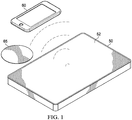
- FIG. 1 shows an example of a wireless power transmission system in accordance with various embodiments.
- a wireless power transmitter 50 can be used for wirelessly transmitting power to a wireless power receiver 60.
- the wireless power receiver 60 may be a coffee cup warmer, appliance, smart phone, audio player, or other type of device to be powered or have its batteries charged by the wireless power transmitter 50.
- the wireless power transmitter 50 is a charging pad on which battery-operated devices can be placed to have their batteries recharged.
- the wireless power transmitter 50 has a surface 52 onto which the wireless power receiver 60 may be placed while charging.
- Reference numeral 65 identifies a foreign object that may be placed (inadvertently) on the wireless power transmitter 50 instead of or in addition to the wireless power receiver 60. Foreign objects that are of concern are objects made of metal.
- the term "foreign object" refers to any metal object that is not the wireless power receiver 60 intended to be charged by the wireless power transmitter 50.
- metal objects may absorb energy from the wireless power transmitter and become warm and possibly hot enough to cause harm.
- the embodiments described herein are directed to determining whether the wireless power transmitter 50 has nothing on in it (a safe condition), only a wireless power receiver 60 on it (also a safe condition), only a foreign object (an unsafe condition), or a wireless power receiver 60 plus a foreign object on the transmitter (also an unsafe condition). If the wireless power transmitter 50 detects the presence of a foreign object, the transmitter may react in any suitable manner, such as by reducing the amount of power wirelessly transferred by the transmitter, or by completely turning off the flow of wireless power.
- the wireless power transmitter 50 includes electronics that cause an LC tank circuit (which includes a transmitting coil) to ring at the resonant frequency of the LC tank circuit, and analyzes the natural response of the LC tank circuit to determine whether a foreign object is present on or near the wireless power transmitter .
- an LC tank circuit which includes a transmitting coil
- FIG. 2 is a block diagram of an example of wireless power transmitter 50 and the wireless power receiver 60.
- the wireless power transmitter 50 includes a controller 112, a power train 114, and an analog-to-digital converter (ADC) 118.
- the ADC 118 may be included in the controller 112.
- the power train 114 may include a pair of power metal oxide semiconductor field effect transistors (MOSFETs) T1 and T2, a coil L1 (inductor) and capacitor C1.
- the transistors T1 and T2 may be turned on and off by the controller 112 via control signals 113 and 115.
- the switch node 117 between the transistors is coupled to the coil L1, and through coil L1 to ground through capacitor C1.
- the coil L1 and capacitor C1 form a tank circuit, which can be made to ring as described herein.
- the controller 112 receives an input voltage 111 and asserts control signals 113, 115 to reciprocally turn the transistors T1 and T2 on an off, so the transistors T1 and T2 are not both turned on at the same time.
- the voltage on node 117 increases to VDD.
- the voltage on node 117 decreases to ground.
- the voltage on node 117 may be a series of positive voltage pulses controlled by the controller 112.
- the voltage pulses on node 117 causes an alternating current to flow through the coil L1 which in turn induces a current in coil L2 in the battery-operated device 60.
- the amount of wireless power transferred by the transmitter 110 can be controlled by the controller 112 varying the frequency and/or duty cycle of the voltage pulses on node 117 or adjusting the voltage level of VDD applied to the transistors.
- the voltage across capacitor C1 is provided to the ADC 118 through DC blocking capacitor C2 and the voltage divider formed by resistors R1 and R2. Accordingly, the ADC 118 receives an analog signal associated with the power train and converts that analog signal to digital values to be provided to the controller 112 for further analysis.
- the analog signal provided to the ADC 118 may be associated with the current through coil L1.
- the wireless power receiver 60 may include the coil L2 noted hereinabove, a capacitor C3, a rectifier 62, a voltage regulator 64, and a load 66.
- the voltage induced across the coil L2 is rectified by rectifier 62 and regulated by voltage regulator 64.
- a regulated voltage then is provided to a load 66, which may include a rechargeable battery, a charging circuit, and functional circuitry of the battery-operated device.
- Ferrite plates (not shown) may also be provided behind coils L1 and L2. Ferrite plates are useful to help control the direction of the magnetic field created by current in coil L1.
- FIG. 3 illustrates the response of the power train 114 of the transmitter 110 to an excitation 120.
- the excitation 120 includes multiple pulses applied to the LC tank circuit, including coil L1 and capacitor C1. These pulses may be initiated by the controller 112.
- the positive voltage level of each pulse is created by the controller 112 turning on transistor T1 and turning off transistor T2.
- the lower voltage level of each pulse is created by the controller 112 turning on transistor T2 and turning off transistor T1.
- three voltage pulses are generated to excite the power train 114, but can be other than three pulses in other examples.
- the frequency of the voltage pulses i.e., the number of pulses per unit of time
- the power train will ring as illustrated at 125.
- the ringing will dampen and eventually die out.
- the frequency of the ringing oscillations is the "resonant frequency" of the LC tank circuit of the power train 114.
- the ringing dies down at a rate that is referred to as the "rate of decay" ("decay rate").
- the peak-to-peak amplitude of the ringing just after cessation of the excitation is referred to as the "initial peak amplitude.”
- the ringing will last for a period of time before the ringing signal is lost in ambient circuit noise, and this period of time is referred to as the ringing "duration.”
- the controller 112 causes an excitation 120 (multiple pulses) to be provided to the power train 114 and analyzes the resulting ringing data 125 upon completion of the excitation pulses to determine whether: (a) no object is present on the wireless power transmitter 50; (b) only a wireless power receiver 60 is present on the transmitter; or (c) a foreign object 65 is present on the transmitter (with or without a receiver).
- the frequency of the excitation pulses are as close to the actual resonant frequency of the power train 114 as possible.
- the resonant frequency of the power train may be altered by the presence of a foreign object 65 and/or wireless power receiver 60 in the magnetic field.
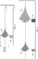
- the controller 112 may cause two excitations to occur as is shown in FIG. 4 .
- the first excitation 130 includes a series of pulses at a frequency that is likely close enough to the resonant frequency of the power train to elicit a ringing response 135.
- the resonant frequency may be 100 KHz with no object on the wireless power transmitter 50, higher than 100 KHz if a foreign object is on the transmitter, and lower than 100 KHz if a wireless power receiver 60 with ferrite is present on the transmitter.
- the frequency of the first excitation 130 may be at 100 KHz, but the resonant frequency may be different than 100 KHz.
- a frequency within the predicted range of possible resonant frequencies is selected for the first excitation 130.
- the controller 112 causes the pulses to be applied to the power train 114 to thereby cause the power train to ring as illustrated at 135.
- the ADC 118 digitizes the ringing analog signal, and the controller 112 then receives digital values from the ADC of the ringing signal upon completion of the excitation pulses.
- the controller 112 determines the frequency of the ringing signal.
- the determined frequency is the resonant frequency of the power train, as may be influenced by the present of a wireless power receiver and/or foreign object.
- the controller 112 then may again excite the power train 114 with another series of pulses (excitation 140) at the determined resonant frequency.
- the power train again rings (145), but because it was excited at its actual resonant frequency, the ringing is larger in amplitude and duration as shown.
- This latter data (collected based on an excitation at the resonant frequency) is analyzed to determine whether a wireless power receiver or a foreign object is on the wireless power transmitter 50.
- the number of pulses for the second excitation 140 may be the same or different than the number of pulses in the initial excitation 130.
- the resonant frequency may be calculated by the controller 112 counting the number of oscillations of the ringing signal 135 over a period of time and dividing by the time period. Oscillations may be identified by zero-crosses after subtracting the mean from the data, and time may be measured by counting the number of clock signals of a known clock frequency in the controller between ADC samples. This will indicate the amount of time per sample (such as number of nsec per sample). This time reference can then be used in determining the elapsed time for a given number of oscillations.
- the decay rate can also be computed by the controller 112.
- the peak-to-peak amplitude of each oscillation may be stored in the controller 112, until the peak-to-amplitude becomes so small that the noise itself may cause zero-crossings.
- the controller 112 may determine the decay rate by determining the difference between the initial peak amplitude of the ringing signal and the amplitude of the smallest oscillation, and dividing that difference by the number of cycles during the elapsed period of time between those two amplitudes. The resulting decay rate may be given in terms of volts per cycle.
- the duration of the ringing signal also may be computed by the controller 112.
- the duration may be determined by determining the amount of elapsed time between: the initial oscillation immediately upon the end of the last excitation pulse; and the point in time at which the peak-to-peak amplitude falls so low as to be overwhelmed by noise, which is a threshold that may be predetermined.
- FIGS. 5-8 depict four different scenarios in which: nothing is on the wireless power transmitter 50 ( FIG. 5 ); only a wireless power receiver 60 is on the transmitter ( FIG. 6 ); only a foreign object 65 is on the transmitter ( FIG. 7 ); or both a foreign object and a wireless power receiver are on the transmitter ( FIG. 8 ).
- FIG. 7 illustrates the ringing response with only a foreign object on the transmitter.
- the resulting resonant frequency is relatively high and is characterized by a relatively rapid decay.
- the resonant frequency is smaller than the case ( FIG. 7 ) in which the pad has only a foreign object, but larger than with only a wireless power receiver 60 on the pad ( FIG. 6 ).
- a wireless power transmitter 50 includes at least an ADC 118 and a controller 112, and the ADC 118 may or may not be part of the controller 112.
- the ADC 118 is configured to convert an analog signal associated with the power train 114 to digital values.
- the controller 112 is configured to cause excitation pulses to be applied to the power train 114 to thereby cause the power train to ring.
- the controller 112 is further configured to receive digital values from the ADC acquired while the power train is ringing.
- the controller is configured to determine whether a wireless power receiver is present on or near the surface 52 of the transmitter 50 or whether a foreign object is present on or near the transmitter's surface 52.
- FIGS. 10-12 include methods that implement this functionality and will be discussed hereinbelow.
- the controller 112 is configured to determine that no wireless power receiver nor foreign object is present on the wireless power transmitter based on the ringing's duration exceeding an EMPTY WIRELESS POWER TRANSMITTER DURATION threshold.
- the EMPTY WIRELESS POWER TRANSMITTER DURATION threshold is a predetermined time threshold for which, if the power train ringing exceeds this time threshold, it can be safely assumed that the surface 52 of the transmitter 50 is empty. This time threshold may be unique to the particular characteristics of the transmitter (such as the size of the coil L1, and the capacitance of capacitance C1) and may be chosen based on experimental testing.
- the controller 112 is configured to determine an initial peak amplitude of the digital values from the ADC at the beginning of the ringing period.
- the initial peak amplitude (I.P.A.) is also illustrated in FIG. 7 and is the peak-to-peak amplitude of the ringing just upon expiration of the last excitation pulse.
- the controller further is configured to determine a decay rate of the digital values during the ringing period.
- the controller can determine that a foreign object is present on the transmitter based on the initial peak amplitude exceeding a PEAK AMPLITUDE threshold and the decay rate exceeding a DECAY RATE threshold.
- the PEAK AMPLITUDE threshold and the DECAY RATE threshold both may be determined based on the resonant frequency of the power train 114.
- PEAK AMPL THRESH is the PEAK AMPLITUDE threshold
- PEAK OFFSET and PEAK GAIN are experimentally determined based on the transmitter characteristics to reflect the expected change in the PEAK AMPLITUDE for a given shift in frequency
- RES FREQ is the resonant frequency of the power train when nothing is present on the transmitter (this value is determined in advance and used as a constant in the evaluation of the response)
- FP FREQ is measured system resonant frequency as determined by the controller after the ping as described hereinabove.
- controller 112 determines that either the initial peak amplitude does not exceed the PEAK AMPLITUDE threshold or the decay rate does not exceed the DECAY RATE threshold, then the controller determines that a wireless power receiver 60, with no foreign object, is present on or near the wireless power transmitter.
- the controller 112 determines whether the wireless power transmitter is empty, based (as explained hereinabove) on whether the ringing duration exceeds the EMPTY WIRELESS POWER TRANSMITTER DURATION threshold. If such is not the case, then the controller in this example determines whether a foreign object or a wireless power receiver only is present on or near the transmitter based on a comparison of the resonant frequency to corresponding thresholds.
- FIG. 9 illustrates a frequency spectrum with two thresholds, which are a WIRELESS POWER RECEIVER FREQUENCY threshold and a FOREIGN OBJECT FREQUENCY threshold (both predetermined experimentally or otherwise).
- the controller 112 determines that a foreign object is present on or near the charging pad. However, if the resonant frequency of the power train is less than the WIRELESS POWR RECEIVER FREQUENCY threshold, then the controller 112 determines that a wireless power receiver 60 (with no foreign object) is present on or near the transmitter's surface 52.
- the controller is configured to determine the resonant frequency of the power train ringing and to determine that a foreign object is present on the transmitter's surface, based on the resonant frequency exceeding the FOREIGN OBJECT FREQUENCY threshold and based on the ringing's duration not exceeding the EMPTY WIRELESS POWER TRANSMITTER DURATION threshold. Further, the controller is configured to determine that a wireless power receiver (with no foreign object) is present on the transmitter's surface 52, based on the resonant frequency being below the WIRELESS POWER RECEIVER FREQUENCY threshold and based on the ringing's duration not exceeding the EMPTY WIRELESS POWER TRANSMITTER DURATION threshold.
- the controller 112 determines that a wireless power receiver 60 (with no foreign object) is present on or near the transmitter, based on a determination that decay rate is exceeds a DECAY RATE threshold and that the power train's ringing duration exceeds a RING DURATION threshold.
- the DECAY RATE threshold in this example may be the same or different than the DECAY RATE threshold discussed hereinabove.
- the RING DURATION threshold may be less than the EMPTY WIRELESS POWER TRANSMITTER DURATION threshold and may be determined experimentally.
- the controller 112 determines that a foreign object is present on or near the transmitter's surface 52.
- FIG. 10 illustrates a method of determining whether an object is present on the transmitter 50 and, if so, whether that object is a foreign object.
- the method may include any one or more of the operations depicted in various combinations, and in a different order than that shown in FIG. 10 .
- the controller may perform, or caused to be performed some or all of the operations listed.
- the method includes pinging a power train with multiple electrical pulses to thereby cause the power train to ring.
- the controller 112 may ping the power train 114 by controlling the transistors T1 and T2 to turn on an off at a desired frequency (such as the resonant frequency).
- the method further includes determining whether a wireless power receiver is present on a wireless power transmitter or whether a foreign object is present on the transmitter, based on values computed from the power train ringing.
- the method also includes reducing the amount of power wireless transferred by the transmitter 110 upon determining that a foreign object is present on the transmitter. The power transfer may be terminated completely if desired.
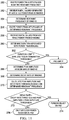
- FIG. 11 illustrates a method of determining whether an object is present on the wireless power transmitter 50 and, if so, whether that object is a foreign object in accordance with another example.
- the method may include any one or more of the operations depicted in various combinations, and in a different order than that shown in FIG. 10 .
- the controller may perform, or caused to be performed some or all of the operations listed.
- the method includes exciting the power train 114 with pulses near the resonant frequency.
- the resonant frequency of the power train varies to some degree depending on whether the transmitter surface 52 is devoid of any object (receiver or foreign object) or whether a foreign object is present, and whether a wireless power receiver is present. It is desirable for the power train to be excited at its resonant frequency. Nevertheless, without knowing whether an object is present (or, if present, without knowing the type of object), the transmitter's controller 112 does not initially know the resonant frequency.
- the frequency of the pulses for the excitation of operation 250 is a predetermined frequency (such as halfway between the lowest and highest anticipated resonance frequencies, or at the resonant frequency of the power train when no object is present).
- the ADC 118 samples the analog ringing signal caused to occur by the excitation of 250, and the digital values generated by the ADC are provided to the controller 112 (operation 252).
- the controller 112 determines the resonant frequency of the ringing, based on the digital values generated by the ADC.
- the method further includes again exciting the power train, but this time the frequency of the excitation pulses are at the resonant frequency determined at 254.
- the digital values from the ADC are received by the controller 112. These values are generated by the ADC while the power train was ringing at its resonant frequency.
- the controller determines the duration associated with the power train ringing. For example, the duration may be the time duration from the end point of the last excitation pulse to the time at which the ringing amplitude drops below a predetermined threshold (such as a threshold approaching the level at which noise may become larger than the signal itself).
- the controller then compares the duration to the EMPTY WIRELESS POWER TRANSMITTER DURATION threshold. If the duration is greater than the EMPTY WIRELESS POWER TRANSMITTER DURATION threshold, the controller determines (at 264) that the pad is empty (i.e., no battery-operated device nor foreign object is present on or near the transmitter 50).
- the method includes the controller determining the initial peak amplitude at the beginning of the ringing period as explained hereinabove.
- the controller determines the decay rate of the ringing.
- the controller calculates the PEAK AMPLITUDE and DECAY RATE thresholds based on the determined resonant frequency. Examples of formulas for these thresholds are provided hereinabove.
- the decay rate and the initial peak amplitude are compared to their corresponding thresholds.
- the controller determines that a foreign object is present on or near the transmitter. Otherwise, at 276, the controller determines that a wireless power receiver with no foreign object is present on or near the transmitter.
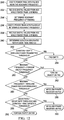
- FIG. 12 is the same as FIG. 11 from operations 250 through 264, so a description of those operations is not repeated.
- the controller has determined that the transmitter has neither a wireless power receiver nor a foreign object on it, based on the length of time of the ringing of the power train.
- the controller compares the resonant frequency to the FOREIGN OBJECT FREQUENCY threshold. If the resonant frequency of the power train is greater than the FOREIGN OBJECT FREQUENCY threshold, then the controller determines (at 282) that a foreign object is present on or near the transmitter.
- the controller compares the resonant frequency to the WIRELESS POWER RECEIVER FREQUENCY threshold. If the resonant frequency of the power train is less than the WIRELESS POWER RECEIVERFREQUENCY threshold, then the controller determines (at 286) that a battery-operated device (with no foreign object) is present on or near the transmitter.
- the method reaches operation 288 when the resonant frequency is between the WIRELESS POWER RECEIVERFREQUENCY threshold and the FOREIGN OBJECT FREQUENCY threshold.
- the controller compares the decay rate to the DECAY RATE threshold and the ringing duration to the RING DURATION threshold. If the decay rate is less than the DECAY RATE threshold and the duration is greater than the RING DURATION threshold, then the controller determines (at 290) that a wireless power receiver (with no foreign object) is present on or near the transmitter. Otherwise, the controller determines (at 292) that a foreign object is present on or near the transmitter.
Landscapes
- Engineering & Computer Science (AREA)
- Computer Networks & Wireless Communication (AREA)
- Power Engineering (AREA)
- Physics & Mathematics (AREA)
- Electromagnetism (AREA)
- Charge And Discharge Circuits For Batteries Or The Like (AREA)
- Life Sciences & Earth Sciences (AREA)
- Acoustics & Sound (AREA)
- Environmental & Geological Engineering (AREA)
- Geology (AREA)
- Remote Sensing (AREA)
- General Life Sciences & Earth Sciences (AREA)
- General Physics & Mathematics (AREA)
- Geophysics (AREA)
- Transmitters (AREA)
Applications Claiming Priority (3)
| Application Number | Priority Date | Filing Date | Title |
|---|---|---|---|
| US201461975501P | 2014-04-04 | 2014-04-04 | |
| US14/667,880 US9939539B2 (en) | 2014-04-04 | 2015-03-25 | Wireless power receiver and/or foreign object detection by a wireless power transmitter |
| PCT/US2015/024559 WO2015154086A1 (en) | 2014-04-04 | 2015-04-06 | Foreign object detection by a wireless power transmitter |
Publications (3)
| Publication Number | Publication Date |
|---|---|
| EP3127215A1 EP3127215A1 (en) | 2017-02-08 |
| EP3127215A4 EP3127215A4 (en) | 2017-09-27 |
| EP3127215B1 true EP3127215B1 (en) | 2020-03-04 |
Family
ID=54209598
Family Applications (1)
| Application Number | Title | Priority Date | Filing Date |
|---|---|---|---|
| EP15774155.4A Active EP3127215B1 (en) | 2014-04-04 | 2015-04-06 | Foreign object detection by a wireless power transmitter |
Country Status (5)
| Country | Link |
|---|---|
| US (1) | US9939539B2 (https=) |
| EP (1) | EP3127215B1 (https=) |
| JP (2) | JP6596486B2 (https=) |
| CN (2) | CN106134037B (https=) |
| WO (1) | WO2015154086A1 (https=) |
Families Citing this family (70)
| Publication number | Priority date | Publication date | Assignee | Title |
|---|---|---|---|---|
| US10587153B2 (en) | 2011-02-01 | 2020-03-10 | Fu Da Tong Technology Co., Ltd. | Intruding metal detection method for induction type power supply system and related supplying-end module |
| US10056944B2 (en) | 2011-02-01 | 2018-08-21 | Fu Da Tong Technology Co., Ltd. | Data determination method for supplying-end module of induction type power supply system and related supplying-end module |
| US10630113B2 (en) | 2011-02-01 | 2020-04-21 | Fu Da Tong Technology Co., Ltd | Power supply device of induction type power supply system and RF magnetic card identification method of the same |
| US10630116B2 (en) | 2011-02-01 | 2020-04-21 | Fu Da Tong Technology Co., Ltd. | Intruding metal detection method for induction type power supply system and related supplying-end module |
| US10038338B2 (en) | 2011-02-01 | 2018-07-31 | Fu Da Tong Technology Co., Ltd. | Signal modulation method and signal rectification and modulation device |
| TWI568125B (zh) | 2015-01-14 | 2017-01-21 | 富達通科技股份有限公司 | 感應式電源供應器之供電模組及其電壓測量方法 |
| US10673287B2 (en) | 2011-02-01 | 2020-06-02 | Fu Da Tong Technology Co., Ltd. | Method and supplying-end module for detecting receiving-end module |
| TWI577108B (zh) * | 2016-05-13 | 2017-04-01 | 富達通科技股份有限公司 | 感應式電源供應器及其金屬異物檢測方法 |
| TWI570427B (zh) | 2015-10-28 | 2017-02-11 | 富達通科技股份有限公司 | 感應式電源供應器及其金屬異物檢測方法 |
| US10312748B2 (en) | 2011-02-01 | 2019-06-04 | Fu Da Tong Techology Co., Ltd. | Signal analysis method and circuit |
| US10951063B2 (en) | 2011-02-01 | 2021-03-16 | Fu Da Tong Technology Co., Ltd. | Supplying-end module of induction type power supply system and signal detection method thereof |
| TWI655824B (zh) * | 2018-04-18 | 2019-04-01 | Fu Da Tong Technology Co., Ltd. | 感應式電源供應器之金屬異物檢測方法及其供電模組 |
| US10615645B2 (en) | 2011-02-01 | 2020-04-07 | Fu Da Tong Technology Co., Ltd | Power supply device of induction type power supply system and NFC device identification method of the same |
| US11128180B2 (en) | 2011-02-01 | 2021-09-21 | Fu Da Tong Technology Co., Ltd. | Method and supplying-end module for detecting receiving-end module |
| TWI669880B (zh) * | 2018-04-27 | 2019-08-21 | 富達通科技股份有限公司 | 感應式電源供應器之金屬異物檢測方法及其供電模組 |
| US10574095B2 (en) | 2011-02-01 | 2020-02-25 | Fu Da Tong Technology Co., Ltd. | Decoding method for signal processing circuit and signal processing circuit using the same |
| US10289142B2 (en) | 2011-02-01 | 2019-05-14 | Fu Da Tong Technology Co., Ltd. | Induction type power supply system and intruding metal detection method thereof |
| EP2845416B1 (en) | 2012-05-02 | 2018-11-21 | Apple Inc. | Methods for detecting and identifying a receiver in an inductive power transfer system |
| KR102283473B1 (ko) | 2012-11-05 | 2021-08-02 | 애플 인크. | 유도 결합된 전력 전송 시스템 |
| CN106464307B (zh) | 2014-06-19 | 2018-08-28 | 皇家飞利浦有限公司 | 无线感应功率传输 |
| EP3158621A4 (en) | 2014-06-20 | 2017-07-12 | PowerbyProxi Limited | Foreign object detection in inductive power transfer field |
| KR102285941B1 (ko) | 2014-08-12 | 2021-08-06 | 애플 인크. | 전력 전달을 위한 시스템 및 방법 |
| US10153665B2 (en) | 2015-01-14 | 2018-12-11 | Fu Da Tong Technology Co., Ltd. | Method for adjusting output power for induction type power supply system and related supplying-end module |
| KR102191406B1 (ko) | 2015-03-04 | 2020-12-16 | 애플 인크. | 유도 전력 전송기 |
| CN107529346B (zh) * | 2015-04-02 | 2021-03-02 | 苹果公司 | 感应电力发射器 |
| US10411524B2 (en) | 2015-06-23 | 2019-09-10 | Witricity Corporation | Systems, methods and apparatuses for guidance and alignment in electric vehicles wireless inductive charging systems |
| KR101683651B1 (ko) * | 2015-10-21 | 2016-12-20 | 현대자동차주식회사 | 무선충전장치의 이음 저감 장치 및 방법 |
| US10199881B2 (en) | 2015-10-23 | 2019-02-05 | Mediatek Inc. | Robust foreign objects detection |
| US10581281B2 (en) * | 2015-10-23 | 2020-03-03 | Mediatek Inc. | In situ coil parameter measurements and foreign objects detection |
| CN108401471B (zh) | 2015-11-19 | 2021-06-25 | 苹果公司 | 感应式电力发射器 |
| JP6700470B2 (ja) | 2016-04-04 | 2020-05-27 | アップル インコーポレイテッドApple Inc. | 誘導電力送信機 |
| WO2017204663A1 (en) | 2016-05-25 | 2017-11-30 | Powerbyproxi Limited | A coil arrangement |
| WO2017209630A1 (en) | 2016-06-01 | 2017-12-07 | Powerbyproxi Limited | A powered joint with wireless transfer |
| CN109952503B (zh) | 2016-07-01 | 2022-09-09 | Lg伊诺特有限公司 | 用于检测异物的方法及其设备和系统 |
| KR102617560B1 (ko) | 2016-08-23 | 2023-12-27 | 엘지이노텍 주식회사 | 이물질 검출 방법 및 그를 위한 장치 및 시스템 |
| SG10201708902RA (en) | 2017-02-02 | 2018-09-27 | Apple Inc | Wireless Charging System With Object Detection |
| US10511197B2 (en) * | 2017-02-02 | 2019-12-17 | Apple Inc. | Wireless charging system with object detection |
| US10910885B2 (en) * | 2017-02-08 | 2021-02-02 | Mitsubishi Electric Engineering Company, Limited | Power transmission-side apparatus |
| US10770921B2 (en) * | 2017-02-10 | 2020-09-08 | Apple Inc. | Wireless charging system with start-up negotiation |
| EP3410568A1 (en) * | 2017-05-30 | 2018-12-05 | Koninklijke Philips N.V. | Foreign object detection in a wireless power transfer system |
| CN109120075B (zh) * | 2017-06-22 | 2023-11-28 | 恩智浦美国有限公司 | 检测无线充电发送器的充电区域内物体的方法与装置 |
| US11171502B2 (en) * | 2018-02-23 | 2021-11-09 | Aira, Inc. | Free positioning charging pad |
| EP3553918B1 (en) | 2018-04-09 | 2020-11-25 | NXP USA, Inc. | A power transmitter unit |
| EP3553917B1 (en) | 2018-04-09 | 2021-09-01 | NXP USA, Inc. | A power transmitter unit |
| CN109038850B (zh) * | 2018-06-25 | 2020-07-24 | 华为技术有限公司 | 一种检测无线充电系统中金属异物的装置、设备及方法 |
| TWI738029B (zh) | 2018-07-19 | 2021-09-01 | 新加坡商聯發科技(新加坡)私人有限公司 | 無線功率傳輸系統之異物偵測技術 |
| EP3818620A4 (en) | 2018-07-19 | 2022-03-23 | MediaTek Singapore Pte. Ltd. | Detecting foreign objects in wireless power transfer systems |
| KR102554226B1 (ko) * | 2018-09-04 | 2023-07-10 | 주식회사 히타치엘지 데이터 스토리지 코리아 | 무선 전력 전송 장치 및 방법 |
| EP3672093B1 (en) * | 2018-12-19 | 2024-02-21 | Continental Automotive Technologies GmbH | A method for cooperative use of a wireless communication interface and a wireless charging interface |
| US11063480B2 (en) * | 2019-05-28 | 2021-07-13 | Aira, Inc. | Adaptive passive Ping |
| CN111817454B (zh) * | 2019-07-26 | 2024-01-30 | 山东帕沃思新能源科技有限公司 | 无线供电装置及其控制方法 |
| CN112787418B (zh) * | 2019-11-04 | 2023-11-14 | 北京小米移动软件有限公司 | 无线充电发射器、无线充电方法 |
| EP3840177B1 (en) * | 2019-12-19 | 2026-03-25 | BRUSA Elektronik AG | An object detection apparatus for an inductive charging system |
| CN115663969A (zh) * | 2020-02-12 | 2023-01-31 | 华为数字能源技术有限公司 | 一种无线充电电路、无线充电方法、设备和系统 |
| JP7566483B2 (ja) * | 2020-03-31 | 2024-10-15 | キヤノン株式会社 | 送電装置、送電装置が行う方法およびプログラム |
| US11398752B2 (en) * | 2020-06-04 | 2022-07-26 | Aira, Inc. | Zero-crossing slotted foreign object detection |
| CN113852218A (zh) * | 2020-06-28 | 2021-12-28 | 伏达半导体(合肥)有限公司 | 用于无线功率传输系统的物体检测设备和方法 |
| US20220052565A1 (en) * | 2020-08-15 | 2022-02-17 | Aira, Inc. | Resonant Reflection Device Detection |
| US11152822B1 (en) | 2020-09-30 | 2021-10-19 | Stmicroelectronics Asia Pacific Pte Ltd | Foreign objection detection sensing circuit for wireless power transmission systems |
| FR3117220B1 (fr) * | 2020-12-03 | 2022-10-21 | Continental Automotive Gmbh | Procede de detection d’un objet metallique parasite sur une surface de charge et dispositif de charge associe |
| JP7809459B2 (ja) * | 2021-06-29 | 2026-02-02 | キヤノン株式会社 | 送電装置、受電装置、それらが行う方法、及び、プログラム |
| US20230053186A1 (en) * | 2021-08-16 | 2023-02-16 | Aira, Inc. | Transmitter Coil Power Foreign Object Detection |
| JP7802811B2 (ja) * | 2021-09-17 | 2026-01-20 | キヤノン株式会社 | 送電装置および受電装置 |
| WO2023106778A1 (ko) * | 2021-12-07 | 2023-06-15 | 삼성전자 주식회사 | 이물질 감지 방법 및 전자 장치 |
| JP7703437B2 (ja) * | 2021-12-14 | 2025-07-07 | キヤノン株式会社 | 受電装置、受電装置の制御方法およびプログラム |
| CN117154862A (zh) * | 2022-06-01 | 2023-12-01 | 深圳英集芯科技股份有限公司 | 无线充电方法和无线充电电路及相关装置 |
| DE102023123588A1 (de) * | 2023-09-01 | 2025-03-06 | Turck Holding Gmbh | Verfahren zum Betreiben eines induktiven Kopplers |
| KR20260044987A (ko) * | 2023-09-08 | 2026-04-02 | 애플 인크. | 무선 전력 전송을 위한 객체 검출 |
| WO2025170764A1 (en) * | 2024-02-05 | 2025-08-14 | Apple Inc. | Power accounting for wireless power transfer |
| US20260066710A1 (en) * | 2024-09-05 | 2026-03-05 | Nxp B.V. | Q-factor continuous excitation method and apparatus |
Family Cites Families (38)
| Publication number | Priority date | Publication date | Assignee | Title |
|---|---|---|---|---|
| JPH09326736A (ja) | 1996-06-03 | 1997-12-16 | Mitsubishi Electric Corp | ワイヤレス送受信システム用2次側回路装置およびワイヤレス送受信システム用誘導コイル |
| JP2000032684A (ja) | 1998-07-08 | 2000-01-28 | Toyota Autom Loom Works Ltd | 充電回路および方法 |
| US6870792B2 (en) | 2000-04-04 | 2005-03-22 | Irobot Corporation | Sonar Scanner |
| KR100566220B1 (ko) | 2001-01-05 | 2006-03-29 | 삼성전자주식회사 | 무접점 배터리 충전기 |
| GB2414120B (en) | 2004-05-11 | 2008-04-02 | Splashpower Ltd | Controlling inductive power transfer systems |
| JP2006060909A (ja) * | 2004-08-19 | 2006-03-02 | Seiko Epson Corp | 非接触電力伝送装置 |
| US7239103B2 (en) | 2005-02-25 | 2007-07-03 | International Rectifier Corporation | Synchronous motor startup lock detection circuit and method |
| KR20070104777A (ko) | 2006-04-24 | 2007-10-29 | 엘에스전선 주식회사 | 과전류 감지 수단을 구비하는 무선 충전 장치 |
| JP4494426B2 (ja) | 2007-02-16 | 2010-06-30 | セイコーエプソン株式会社 | 送電制御装置、受電制御装置、無接点電力伝送システム、送電装置、受電装置および電子機器 |
| WO2009069844A1 (en) * | 2007-11-30 | 2009-06-04 | Chun-Kil Jung | Multiple non-contact charging system of wireless power transmision and control method thereof |
| AU2008339692B2 (en) | 2007-12-21 | 2014-08-21 | Access Business Group International Llc | Circuitry for inductive power transfer |
| US9178387B2 (en) * | 2008-05-13 | 2015-11-03 | Qualcomm Incorporated | Receive antenna for wireless power transfer |
| JP4815485B2 (ja) | 2008-11-14 | 2011-11-16 | 東光株式会社 | 非接触電力伝送装置 |
| JP5258521B2 (ja) | 2008-11-14 | 2013-08-07 | トヨタ自動車株式会社 | 給電システム |
| JP4640496B2 (ja) * | 2008-12-02 | 2011-03-02 | カシオ計算機株式会社 | 電力伝送装置 |
| JP2010288431A (ja) | 2009-06-15 | 2010-12-24 | Sanyo Electric Co Ltd | 電池内蔵機器と充電台 |
| US20110057606A1 (en) | 2009-09-04 | 2011-03-10 | Nokia Corpation | Safety feature for wireless charger |
| GB2490074B (en) * | 2010-02-08 | 2014-02-19 | Access Business Group Int Llc | Input parasitic metal detection |
| WO2011156768A2 (en) | 2010-06-11 | 2011-12-15 | Mojo Mobility, Inc. | System for wireless power transfer that supports interoperability, and multi-pole magnets for use therewith |
| JP2012016125A (ja) * | 2010-06-30 | 2012-01-19 | Panasonic Electric Works Co Ltd | 非接触給電システム及び非接触給電システムの金属異物検出装置 |
| KR101184503B1 (ko) * | 2010-08-13 | 2012-09-20 | 삼성전기주식회사 | 무선 전력 전송 장치 및 그 전송 방법 |
| JP6094762B2 (ja) | 2010-09-14 | 2017-03-15 | ウィトリシティ コーポレーション | 無線エネルギー分配システム |
| US9294153B2 (en) | 2010-09-23 | 2016-03-22 | Texas Instruments Incorporated | Systems and methods of wireless power transfer with interference detection |
| US9231412B2 (en) * | 2010-12-29 | 2016-01-05 | National Semiconductor Corporation | Resonant system for wireless power transmission to multiple receivers |
| US10115520B2 (en) | 2011-01-18 | 2018-10-30 | Mojo Mobility, Inc. | Systems and method for wireless power transfer |
| US9252846B2 (en) * | 2011-09-09 | 2016-02-02 | Qualcomm Incorporated | Systems and methods for detecting and identifying a wireless power device |
| US9450648B2 (en) | 2011-10-13 | 2016-09-20 | Integrated Device Technology, Inc. | Apparatus, system, and method for detecting a foreign object in an inductive wireless power transfer system |
| JP6019581B2 (ja) * | 2011-12-26 | 2016-11-02 | ソニー株式会社 | 検知装置、検知システム、送電装置、非接触電力伝送システム及び検知方法 |
| JP6090172B2 (ja) * | 2012-01-17 | 2017-03-08 | パナソニックIpマネジメント株式会社 | 無接点充電方法 |
| US9502922B2 (en) * | 2012-02-29 | 2016-11-22 | Panasonic Intellectual Property Management Co., Ltd. | Charging apparatus |
| WO2013164831A1 (en) | 2012-05-03 | 2013-11-07 | Powermat Technologies Ltd. | System and method for triggering power transfer across an inductive power coupling and non resonant transmission |
| JP5915428B2 (ja) * | 2012-07-12 | 2016-05-11 | ソニー株式会社 | 駆動回路、及び、駆動方法 |
| US9410823B2 (en) * | 2012-07-13 | 2016-08-09 | Qualcomm Incorporated | Systems, methods, and apparatus for detection of metal objects in a predetermined space |
| US9154189B2 (en) * | 2012-08-17 | 2015-10-06 | Qualcomm Incorporated | Wireless power system with capacitive proximity sensing |
| KR102096560B1 (ko) * | 2012-09-11 | 2020-04-03 | 필립스 아이피 벤쳐스 비.브이. | 무선 전력 제어 |
| US9178361B2 (en) | 2012-09-27 | 2015-11-03 | ConvenientPower, Ltd. | Methods and systems for detecting foreign objects in a wireless charging system |
| CN105226843B (zh) * | 2014-05-27 | 2017-09-15 | 松下知识产权经营株式会社 | 无线电力传输系统以及无线电力传输系统的送电装置 |
| US9559547B2 (en) * | 2014-06-10 | 2017-01-31 | Nokia Technologies Oy | User indication of compatible wireless charging area |
-
2015
- 2015-03-25 US US14/667,880 patent/US9939539B2/en active Active
- 2015-04-06 EP EP15774155.4A patent/EP3127215B1/en active Active
- 2015-04-06 WO PCT/US2015/024559 patent/WO2015154086A1/en not_active Ceased
- 2015-04-06 CN CN201580016966.7A patent/CN106134037B/zh active Active
- 2015-04-06 CN CN201910710375.XA patent/CN110417132B/zh active Active
- 2015-04-06 JP JP2017503802A patent/JP6596486B2/ja active Active
-
2019
- 2019-09-30 JP JP2019178390A patent/JP6923888B2/ja active Active
Non-Patent Citations (1)
| Title |
|---|
| None * |
Also Published As
| Publication number | Publication date |
|---|---|
| CN106134037B (zh) | 2019-08-23 |
| JP6596486B2 (ja) | 2019-10-23 |
| US20150285926A1 (en) | 2015-10-08 |
| JP2020018166A (ja) | 2020-01-30 |
| JP6923888B2 (ja) | 2021-08-25 |
| WO2015154086A1 (en) | 2015-10-08 |
| CN110417132B (zh) | 2023-05-12 |
| JP2017511117A (ja) | 2017-04-13 |
| US9939539B2 (en) | 2018-04-10 |
| EP3127215A1 (en) | 2017-02-08 |
| CN110417132A (zh) | 2019-11-05 |
| EP3127215A4 (en) | 2017-09-27 |
| CN106134037A (zh) | 2016-11-16 |
Similar Documents
| Publication | Publication Date | Title |
|---|---|---|
| EP3127215B1 (en) | Foreign object detection by a wireless power transmitter | |
| TWI710196B (zh) | 執行異物檢測的方法和裝置 | |
| EP2845290B1 (en) | System and method for triggering power transfer across an inductive power coupling and non resonant transmission | |
| JP5860532B2 (ja) | 埋込可能な医療装置の充電 | |
| EP3046220B1 (en) | Charging control device, charging control method and wireless power receiving device equipped with same | |
| KR101579713B1 (ko) | 비접촉 급전 시스템 | |
| EP3451491A1 (en) | Methods and systems for foreign objection detection in wireless energy transfer systems | |
| US11996699B2 (en) | Receiving unit, transmission unit, power transmission system and method for wireless power transmission | |
| EP2737331B1 (en) | Systems and methods of detecting a change in object presence in a magnetic field | |
| JP5884610B2 (ja) | 受電装置、受電装置の制御方法、および、給電システム | |
| CN107015716B (zh) | 位置指示器和位置指示方法 | |
| EP3393009B1 (en) | Detecting foreign objects in wireless power transfer systems | |
| CN110959242A (zh) | 无线功率传输系统中的异物检测 | |
| CN110494321A (zh) | 用于运行感应充电设备的方法 | |
| CN114157052A (zh) | 异物和友好金属的检测 | |
| KR101987276B1 (ko) | 데이터 수신 장치 및 수신 방법, 데이터 전송 장치, 데이터 통신 시스템 | |
| CN117081270A (zh) | 无线电力传输器以及无线电力传输方法 | |
| CN111279581B (zh) | 从能量发送设备至用电器的无线能量传输的方法以及执行该方法的无线能量发送设备 | |
| KR20210092404A (ko) | 큐 인자 측정 장치 및 그 방법 | |
| KR20200078197A (ko) | 무선전력 송신장치를 검출하는 방법 및 이를 위한 무선전력 수신장치 |
Legal Events
| Date | Code | Title | Description |
|---|---|---|---|
| STAA | Information on the status of an ep patent application or granted ep patent |
Free format text: STATUS: THE INTERNATIONAL PUBLICATION HAS BEEN MADE |
|
| PUAI | Public reference made under article 153(3) epc to a published international application that has entered the european phase |
Free format text: ORIGINAL CODE: 0009012 |
|
| STAA | Information on the status of an ep patent application or granted ep patent |
Free format text: STATUS: REQUEST FOR EXAMINATION WAS MADE |
|
| 17P | Request for examination filed |
Effective date: 20161104 |
|
| AK | Designated contracting states |
Kind code of ref document: A1 Designated state(s): AL AT BE BG CH CY CZ DE DK EE ES FI FR GB GR HR HU IE IS IT LI LT LU LV MC MK MT NL NO PL PT RO RS SE SI SK SM TR |
|
| AX | Request for extension of the european patent |
Extension state: BA ME |
|
| DAV | Request for validation of the european patent (deleted) | ||
| DAX | Request for extension of the european patent (deleted) | ||
| A4 | Supplementary search report drawn up and despatched |
Effective date: 20170830 |
|
| RIC1 | Information provided on ipc code assigned before grant |
Ipc: H03M 1/12 20060101ALI20170824BHEP Ipc: H02J 50/60 20160101ALI20170824BHEP Ipc: H02J 50/12 20160101ALI20170824BHEP Ipc: H03J 1/06 20060101AFI20170824BHEP |
|
| REG | Reference to a national code |
Ref country code: DE Ref legal event code: R079 Ref document number: 602015048211 Country of ref document: DE Free format text: PREVIOUS MAIN CLASS: H02J0050000000 Ipc: H02J0005000000 |
|
| RIC1 | Information provided on ipc code assigned before grant |
Ipc: H02J 5/00 20160101AFI20190829BHEP Ipc: H03J 1/06 20060101ALI20190829BHEP Ipc: H02J 50/12 20160101ALI20190829BHEP Ipc: H03M 1/12 20060101ALI20190829BHEP Ipc: H02J 50/60 20160101ALI20190829BHEP Ipc: H02J 7/00 20060101ALI20190829BHEP Ipc: H02J 7/02 20160101ALI20190829BHEP |
|
| GRAP | Despatch of communication of intention to grant a patent |
Free format text: ORIGINAL CODE: EPIDOSNIGR1 |
|
| STAA | Information on the status of an ep patent application or granted ep patent |
Free format text: STATUS: GRANT OF PATENT IS INTENDED |
|
| INTG | Intention to grant announced |
Effective date: 20191004 |
|
| GRAS | Grant fee paid |
Free format text: ORIGINAL CODE: EPIDOSNIGR3 |
|
| GRAA | (expected) grant |
Free format text: ORIGINAL CODE: 0009210 |
|
| STAA | Information on the status of an ep patent application or granted ep patent |
Free format text: STATUS: THE PATENT HAS BEEN GRANTED |
|
| AK | Designated contracting states |
Kind code of ref document: B1 Designated state(s): AL AT BE BG CH CY CZ DE DK EE ES FI FR GB GR HR HU IE IS IT LI LT LU LV MC MK MT NL NO PL PT RO RS SE SI SK SM TR |
|
| REG | Reference to a national code |
Ref country code: GB Ref legal event code: FG4D |
|
| REG | Reference to a national code |
Ref country code: CH Ref legal event code: EP |
|
| REG | Reference to a national code |
Ref country code: AT Ref legal event code: REF Ref document number: 1241486 Country of ref document: AT Kind code of ref document: T Effective date: 20200315 |
|
| REG | Reference to a national code |
Ref country code: DE Ref legal event code: R096 Ref document number: 602015048211 Country of ref document: DE |
|
| REG | Reference to a national code |
Ref country code: IE Ref legal event code: FG4D |
|
| PG25 | Lapsed in a contracting state [announced via postgrant information from national office to epo] |
Ref country code: NO Free format text: LAPSE BECAUSE OF FAILURE TO SUBMIT A TRANSLATION OF THE DESCRIPTION OR TO PAY THE FEE WITHIN THE PRESCRIBED TIME-LIMIT Effective date: 20200604 Ref country code: RS Free format text: LAPSE BECAUSE OF FAILURE TO SUBMIT A TRANSLATION OF THE DESCRIPTION OR TO PAY THE FEE WITHIN THE PRESCRIBED TIME-LIMIT Effective date: 20200304 Ref country code: FI Free format text: LAPSE BECAUSE OF FAILURE TO SUBMIT A TRANSLATION OF THE DESCRIPTION OR TO PAY THE FEE WITHIN THE PRESCRIBED TIME-LIMIT Effective date: 20200304 |
|
| REG | Reference to a national code |
Ref country code: NL Ref legal event code: MP Effective date: 20200304 |
|
| PG25 | Lapsed in a contracting state [announced via postgrant information from national office to epo] |
Ref country code: BG Free format text: LAPSE BECAUSE OF FAILURE TO SUBMIT A TRANSLATION OF THE DESCRIPTION OR TO PAY THE FEE WITHIN THE PRESCRIBED TIME-LIMIT Effective date: 20200604 Ref country code: GR Free format text: LAPSE BECAUSE OF FAILURE TO SUBMIT A TRANSLATION OF THE DESCRIPTION OR TO PAY THE FEE WITHIN THE PRESCRIBED TIME-LIMIT Effective date: 20200605 Ref country code: SE Free format text: LAPSE BECAUSE OF FAILURE TO SUBMIT A TRANSLATION OF THE DESCRIPTION OR TO PAY THE FEE WITHIN THE PRESCRIBED TIME-LIMIT Effective date: 20200304 Ref country code: LV Free format text: LAPSE BECAUSE OF FAILURE TO SUBMIT A TRANSLATION OF THE DESCRIPTION OR TO PAY THE FEE WITHIN THE PRESCRIBED TIME-LIMIT Effective date: 20200304 Ref country code: HR Free format text: LAPSE BECAUSE OF FAILURE TO SUBMIT A TRANSLATION OF THE DESCRIPTION OR TO PAY THE FEE WITHIN THE PRESCRIBED TIME-LIMIT Effective date: 20200304 |
|
| REG | Reference to a national code |
Ref country code: LT Ref legal event code: MG4D |
|
| PG25 | Lapsed in a contracting state [announced via postgrant information from national office to epo] |
Ref country code: NL Free format text: LAPSE BECAUSE OF FAILURE TO SUBMIT A TRANSLATION OF THE DESCRIPTION OR TO PAY THE FEE WITHIN THE PRESCRIBED TIME-LIMIT Effective date: 20200304 |
|
| PG25 | Lapsed in a contracting state [announced via postgrant information from national office to epo] |
Ref country code: ES Free format text: LAPSE BECAUSE OF FAILURE TO SUBMIT A TRANSLATION OF THE DESCRIPTION OR TO PAY THE FEE WITHIN THE PRESCRIBED TIME-LIMIT Effective date: 20200304 Ref country code: PT Free format text: LAPSE BECAUSE OF FAILURE TO SUBMIT A TRANSLATION OF THE DESCRIPTION OR TO PAY THE FEE WITHIN THE PRESCRIBED TIME-LIMIT Effective date: 20200729 Ref country code: IS Free format text: LAPSE BECAUSE OF FAILURE TO SUBMIT A TRANSLATION OF THE DESCRIPTION OR TO PAY THE FEE WITHIN THE PRESCRIBED TIME-LIMIT Effective date: 20200704 Ref country code: SK Free format text: LAPSE BECAUSE OF FAILURE TO SUBMIT A TRANSLATION OF THE DESCRIPTION OR TO PAY THE FEE WITHIN THE PRESCRIBED TIME-LIMIT Effective date: 20200304 Ref country code: LT Free format text: LAPSE BECAUSE OF FAILURE TO SUBMIT A TRANSLATION OF THE DESCRIPTION OR TO PAY THE FEE WITHIN THE PRESCRIBED TIME-LIMIT Effective date: 20200304 Ref country code: EE Free format text: LAPSE BECAUSE OF FAILURE TO SUBMIT A TRANSLATION OF THE DESCRIPTION OR TO PAY THE FEE WITHIN THE PRESCRIBED TIME-LIMIT Effective date: 20200304 Ref country code: CZ Free format text: LAPSE BECAUSE OF FAILURE TO SUBMIT A TRANSLATION OF THE DESCRIPTION OR TO PAY THE FEE WITHIN THE PRESCRIBED TIME-LIMIT Effective date: 20200304 Ref country code: RO Free format text: LAPSE BECAUSE OF FAILURE TO SUBMIT A TRANSLATION OF THE DESCRIPTION OR TO PAY THE FEE WITHIN THE PRESCRIBED TIME-LIMIT Effective date: 20200304 Ref country code: SM Free format text: LAPSE BECAUSE OF FAILURE TO SUBMIT A TRANSLATION OF THE DESCRIPTION OR TO PAY THE FEE WITHIN THE PRESCRIBED TIME-LIMIT Effective date: 20200304 |
|
| REG | Reference to a national code |
Ref country code: AT Ref legal event code: MK05 Ref document number: 1241486 Country of ref document: AT Kind code of ref document: T Effective date: 20200304 |
|
| REG | Reference to a national code |
Ref country code: CH Ref legal event code: PL |
|
| REG | Reference to a national code |
Ref country code: DE Ref legal event code: R097 Ref document number: 602015048211 Country of ref document: DE |
|
| PG25 | Lapsed in a contracting state [announced via postgrant information from national office to epo] |
Ref country code: MC Free format text: LAPSE BECAUSE OF FAILURE TO SUBMIT A TRANSLATION OF THE DESCRIPTION OR TO PAY THE FEE WITHIN THE PRESCRIBED TIME-LIMIT Effective date: 20200304 |
|
| PLBE | No opposition filed within time limit |
Free format text: ORIGINAL CODE: 0009261 |
|
| STAA | Information on the status of an ep patent application or granted ep patent |
Free format text: STATUS: NO OPPOSITION FILED WITHIN TIME LIMIT |
|
| PG25 | Lapsed in a contracting state [announced via postgrant information from national office to epo] |
Ref country code: LI Free format text: LAPSE BECAUSE OF NON-PAYMENT OF DUE FEES Effective date: 20200430 Ref country code: IT Free format text: LAPSE BECAUSE OF FAILURE TO SUBMIT A TRANSLATION OF THE DESCRIPTION OR TO PAY THE FEE WITHIN THE PRESCRIBED TIME-LIMIT Effective date: 20200304 Ref country code: LU Free format text: LAPSE BECAUSE OF NON-PAYMENT OF DUE FEES Effective date: 20200406 Ref country code: DK Free format text: LAPSE BECAUSE OF FAILURE TO SUBMIT A TRANSLATION OF THE DESCRIPTION OR TO PAY THE FEE WITHIN THE PRESCRIBED TIME-LIMIT Effective date: 20200304 Ref country code: CH Free format text: LAPSE BECAUSE OF NON-PAYMENT OF DUE FEES Effective date: 20200430 Ref country code: AT Free format text: LAPSE BECAUSE OF FAILURE TO SUBMIT A TRANSLATION OF THE DESCRIPTION OR TO PAY THE FEE WITHIN THE PRESCRIBED TIME-LIMIT Effective date: 20200304 |
|
| REG | Reference to a national code |
Ref country code: BE Ref legal event code: MM Effective date: 20200430 |
|
| 26N | No opposition filed |
Effective date: 20201207 |
|
| PG25 | Lapsed in a contracting state [announced via postgrant information from national office to epo] |
Ref country code: PL Free format text: LAPSE BECAUSE OF FAILURE TO SUBMIT A TRANSLATION OF THE DESCRIPTION OR TO PAY THE FEE WITHIN THE PRESCRIBED TIME-LIMIT Effective date: 20200304 Ref country code: BE Free format text: LAPSE BECAUSE OF NON-PAYMENT OF DUE FEES Effective date: 20200430 Ref country code: SI Free format text: LAPSE BECAUSE OF FAILURE TO SUBMIT A TRANSLATION OF THE DESCRIPTION OR TO PAY THE FEE WITHIN THE PRESCRIBED TIME-LIMIT Effective date: 20200304 |
|
| PG25 | Lapsed in a contracting state [announced via postgrant information from national office to epo] |
Ref country code: IE Free format text: LAPSE BECAUSE OF NON-PAYMENT OF DUE FEES Effective date: 20200406 |
|
| PG25 | Lapsed in a contracting state [announced via postgrant information from national office to epo] |
Ref country code: TR Free format text: LAPSE BECAUSE OF FAILURE TO SUBMIT A TRANSLATION OF THE DESCRIPTION OR TO PAY THE FEE WITHIN THE PRESCRIBED TIME-LIMIT Effective date: 20200304 Ref country code: MT Free format text: LAPSE BECAUSE OF FAILURE TO SUBMIT A TRANSLATION OF THE DESCRIPTION OR TO PAY THE FEE WITHIN THE PRESCRIBED TIME-LIMIT Effective date: 20200304 Ref country code: CY Free format text: LAPSE BECAUSE OF FAILURE TO SUBMIT A TRANSLATION OF THE DESCRIPTION OR TO PAY THE FEE WITHIN THE PRESCRIBED TIME-LIMIT Effective date: 20200304 |
|
| PG25 | Lapsed in a contracting state [announced via postgrant information from national office to epo] |
Ref country code: MK Free format text: LAPSE BECAUSE OF FAILURE TO SUBMIT A TRANSLATION OF THE DESCRIPTION OR TO PAY THE FEE WITHIN THE PRESCRIBED TIME-LIMIT Effective date: 20200304 Ref country code: AL Free format text: LAPSE BECAUSE OF FAILURE TO SUBMIT A TRANSLATION OF THE DESCRIPTION OR TO PAY THE FEE WITHIN THE PRESCRIBED TIME-LIMIT Effective date: 20200304 |
|
| P01 | Opt-out of the competence of the unified patent court (upc) registered |
Effective date: 20230523 |
|
| PGFP | Annual fee paid to national office [announced via postgrant information from national office to epo] |
Ref country code: DE Payment date: 20250319 Year of fee payment: 11 |
|
| REG | Reference to a national code |
Ref country code: DE Ref legal event code: R079 Ref document number: 602015048211 Country of ref document: DE Free format text: PREVIOUS MAIN CLASS: H02J0005000000 Ipc: H02J0004250000 |
|
| PGFP | Annual fee paid to national office [announced via postgrant information from national office to epo] |
Ref country code: GB Payment date: 20260319 Year of fee payment: 12 |
|
| PGFP | Annual fee paid to national office [announced via postgrant information from national office to epo] |
Ref country code: FR Payment date: 20260319 Year of fee payment: 12 |