EP3126572B1 - Traegerelement für kuenstliche bodenbelaege und system mit einem solchen traegerelement - Google Patents
Traegerelement für kuenstliche bodenbelaege und system mit einem solchen traegerelement Download PDFInfo
- Publication number
- EP3126572B1 EP3126572B1 EP15720451.2A EP15720451A EP3126572B1 EP 3126572 B1 EP3126572 B1 EP 3126572B1 EP 15720451 A EP15720451 A EP 15720451A EP 3126572 B1 EP3126572 B1 EP 3126572B1
- Authority
- EP
- European Patent Office
- Prior art keywords
- supporting element
- supporting
- bar
- beak
- main body
- Prior art date
- Legal status (The legal status is an assumption and is not a legal conclusion. Google has not performed a legal analysis and makes no representation as to the accuracy of the status listed.)
- Active
Links
Images





Classifications
-
- E—FIXED CONSTRUCTIONS
- E01—CONSTRUCTION OF ROADS, RAILWAYS, OR BRIDGES
- E01C—CONSTRUCTION OF, OR SURFACES FOR, ROADS, SPORTS GROUNDS, OR THE LIKE; MACHINES OR AUXILIARY TOOLS FOR CONSTRUCTION OR REPAIR
- E01C5/00—Pavings made of prefabricated single units
- E01C5/005—Individual couplings or spacer elements for joining the prefabricated units
-
- E—FIXED CONSTRUCTIONS
- E01—CONSTRUCTION OF ROADS, RAILWAYS, OR BRIDGES
- E01C—CONSTRUCTION OF, OR SURFACES FOR, ROADS, SPORTS GROUNDS, OR THE LIKE; MACHINES OR AUXILIARY TOOLS FOR CONSTRUCTION OR REPAIR
- E01C13/00—Pavings or foundations specially adapted for playgrounds or sports grounds; Drainage, irrigation or heating of sports grounds
- E01C13/02—Foundations, e.g. with drainage or heating arrangements
-
- E—FIXED CONSTRUCTIONS
- E01—CONSTRUCTION OF ROADS, RAILWAYS, OR BRIDGES
- E01C—CONSTRUCTION OF, OR SURFACES FOR, ROADS, SPORTS GROUNDS, OR THE LIKE; MACHINES OR AUXILIARY TOOLS FOR CONSTRUCTION OR REPAIR
- E01C3/00—Foundations for pavings
- E01C3/006—Foundations for pavings made of prefabricated single units
-
- E—FIXED CONSTRUCTIONS
- E01—CONSTRUCTION OF ROADS, RAILWAYS, OR BRIDGES
- E01C—CONSTRUCTION OF, OR SURFACES FOR, ROADS, SPORTS GROUNDS, OR THE LIKE; MACHINES OR AUXILIARY TOOLS FOR CONSTRUCTION OR REPAIR
- E01C2201/00—Paving elements
- E01C2201/12—Paving elements vertically interlocking
Definitions
- the present invention refers, in general, to a supporting element for synthetic turfs.
- the present invention refers to a supporting element for synthetic turfs, which is particularly easy to use.
- the known supporting elements used for the laying of synthetic turfs, take the form of perforated grids having standardized dimensions and are laid directly on the bottom of the synthetic turf.
- the drilling obtained on the grids of each element allows water drainage through the holes.
- the grids are connected through iron wires that pass through the holes of the grids. Then, the iron wires are twisted.
- This assembly procedure is long and laborious because it is necessary to bind all the grids one by one after laying them on the ground.
- WO 2011/036600 discloses a supporting element for synthetic turfs comprising a main body shaped with a corrugated profile forming overhanging portions which give a desired yield.
- the supporting element comprises connecting means for connection to another supporting element.
- An aim of the invention is to realize a supporting element overcoming the problems of the prior art.
- Another aim of the invention is to offer a supporting element which is not expensive and is easy to use.
- Another aim of the invention is to reduce the number of elements used to realize the support.
- the supporting element comprises a main body shaped with a corrugated profile and comprising crests and valleys.
- the supporting element comprises one or more beaks disposed on a first side of the main body, and a bar disposed on a second side of the main body.
- the one or more beaks and the bar are adapted to be removably coupled with shape coupling, an arc-of-circle opening being formed in the beak and the bar being shaped to be homologous to the beak.
- the one beak or more beaks develop from a valley upward and the bar develops from a valley upward, the sum of the height of the beak from the valley and the height of the bar from the valley being equal to the height from a valley to a crest, so that the connection of the one or more beaks of a supporting element with the bar of another supporting element allows to maintain the corrugated development of the main body.
- Grooves are provided next to the bar around to enable the one or more beaks to rotate when the bar and the one or more beaks are connected to each other.
- one or more protrusions may be comprised and disposed on a third side of the main body and one or more recesses obtained on a fourth side of the main body.
- the one or more protrusions may be easily connected with the one or more recesses, for instance with a shape coupling with snap removal.
- a plurality of slots may be formed in the main body to allow the fluid drainage through the supporting element itself so as to keep the synthetic turf as dry as possible or to drain any fluids such as rainwater or more.
- one or more inlets may be formed between a crest and a valley in the main body, the shape and/or dimensions of the inlets being preferably different from the shape and/or dimensions of the slots.
- the presence of the one or more inlets makes it possible to provide the supporting element with another element of possible coupling with other supporting elements according to the invention.
- All the above-mentioned aims are also achieved through a system comprising two or more supporting elements.
- the supporting elements may be connected to each other by connecting a beak to a bar.
- the volume occupied by the system can be reduced to a minimum but the connection between the at least two supporting elements is maintained.
- the system comprises a jointing element adapted to be coupled with the supporting elements, forming a further connecting means.
- the jointing element comprises one or more feet, the one or more feet being received in one or more inlets of said supporting elements, wherein the jointing element comprises also a wing adapted to be disposed between the two supporting elements.
- the presence of the wing allows to position more precisely the supporting elements and/or to maintain a useful distance between them.
- the two or more supporting elements may be equal and may be connected so as each supporting element is upside-down in comparison with the preceding one.
- This feature makes possible to use supporting elements that are all equal to each other, without requiring the construction of two or more models of supporting elements that are different from each other, which allows to obtain significant savings in terms of production costs and installation costs.
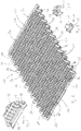
- number 10 denotes a supporting element for synthetic turfs comprising a main body 11 which is substantially rectangular, with prevailing development on a plane and may be inscribed within a parallelepiped.
- the main body 11 is shaped with a corrugated development forming crests 14 and valleys 16 defining the upper and lower limits, respectively, of the parallelepiped in which the main body 11 itself can be inscribed.
- the portions of the supporting element 10 corresponding to the crests 14 and valleys 16 are continuous while leaks 18 are formed in the portions connecting such crests and valleys so as to allow the drainage of water and to act as elastic elements operating as a shock-absorber.
- the main body 11 has a substantially rectangular shape and therefore, its sides correspond two by two so as to be removable connectable.
- the opposite sides are connectable so that it is possible to join together two supporting elements by connecting a first side of a first supporting element to the respective opposite side of a second supporting element, as explained in detail below.
- two grooved beaks 30 protrude from the valley 16 which is the valley closest to the side 20, as represented in detail in Figure 2 .
- the two beaks are formed by following the corrugated development.
- An arc-of-circle bar 32 protrudes along a second side 22, opposite to the first side 20, so that the bar 32 can be grasped by the two beaks 30.
- the bar 32 is raised from the valley opposed to the valley 16.
- two grooves 34 are formed which allow the passing of the elements of each beak 30 when the beak rotates about the bar 32.
- a beak 30 and the bar 32 grasped by the beak 30 itself form a first connecting means between supporting elements according to the invention.
- Two protrusions 36 are provided on the third side, which protrude from the portions in the valleys in proximity to the first side 20 and second side 22.
- each protrusion 36 comprises a tooth 38.
- three recesses 40 are formed in some of the crests on the third side 24.
- the recesses 40 are formed on the fourth, seventh and tenth crest.
- a seat 42 is formed in each recess 40 to receive a tooth 38 of a respective protrusion 36.
- recesses 40 are formed in correspondence of the protrusions 36 of the third side 24 and are arranged according to symmetry while three protrusions 36 protrude in correspondence of the three recesses 40 formed on the third side 24.
- Each tooth 38 is shaped in such a way as to snap-fit in the respective seat 42 with which the tooth is coupled in order to oppose, owing to the coupling, a predetermined resistance to the release.
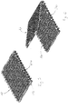
- the compact configuration corresponds to the preferred configuration for the transport of a set of supporting elements according to the invention, which are connected to each other through connecting means, or through the respective beaks and bars, analogous to the beaks 30 and bar 32 described above.
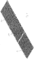
- the three supporting elements which are disposed now according to a stretched configuration, are coupled according to an alternate orientation in which the first supporting element 10 is oriented in an analogous way as shown in Figure 1 , while the second supporting element 110 is oriented in an analogous way as the first supporting element 10.
- the beaks develop from the valley on following a corrugated development and arrive at the level of the crests while the bars are substantially at the level of the valleys.
- the connection of beaks and bars allows to continue the corrugated development of the main body without interruptions.
- three supporting elements realized according to the invention are placed at the side of other three supporting elements arranged according to the extended configuration so that it is possible to connect them to each other through the second connecting means.
- connection takes place between the protrusions and the respective recesses as visible in the detail of Figure 10 , where the tooth 38 reaches the respective seat 42.
- the extent of supporting elements according to the invention can be laid down between the supporting layer and the synthetic turf.
- the extent of supporting elements can be laid down between a draining gravel support layer and a turf made of synthetic grass to realize a synthetic football field or the like.
- the extent of supporting elements according to the invention does not have any interruption in the development of the corrugated profile so as to maintain a uniform behavior for both the draining function and the shock-absorbing function.
- the shock-absorbing function allows to absorb the shocks as required, for example, by the National Amateur League and the F.I.F.A.
- Another advantage of the supporting element according to the invention consists in that the supporting element can be supplied to the operator performing the laying, the supporting element being already connected to other supporting elements through the first connecting means according to the compact configuration in Figure 5 .
- a supporting element may comprise additional recesses and/or protrusions in respect to what described above to obtain greater coupling possibilities between elements and have a greater flexibility for the realization of the support for the synthetic mantle.
- two recesses 90 are visible which are placed in correspondence of the two valley of the main body 11.
- a utilization of such additional recesses may be to allow, in any case, a binding when it is not possible to couple the relative recesses with protrusions or when any protrusion should break.
- a fourth supporting element 310 is shaped in an analogous way as the supporting element 10 as concerns all its components denoted in the figures by references increased by 300 in respect to analogous components of the supporting element 10.
- inlets 370 are formed which are obtained in the main body 311 of the fourth element 310 in a similar way to leaks 318 but with dimensions different from the leaks.
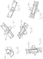
- a jointing element 360 comprises a body 362 developing according to a first main axis.
- Two wings 364 protrude from the body 362, only one of them being shown in Figures 13 and 17 , and four feet 366, only one of them being shown in Figures 13 and 17 .
- the jointing element 360 is symmetric to its first main axis and to a second axis passing through the two wings 364 of the same jointing element 360.
- a compact configuration corresponds o the preferred configuration for the transport of a set of supporting elements according said variant of the invention, which are connected to each other through the first connecting means, or by means of the respective beaks and bars, analogous to the beaks 30 and bar 32 as described above.
- the four supporting elements which are disposed now according to an extended configuration, are coupled according to an alternate orientation in which the fourth supporting element 310 is oriented in an analogous way as visible in Figure 12 while the fifth supporting element 410 is upside-down in comparison with the fourth supporting element 310.
- the sixth supporting element 510 and the seventh supporting element 610 are oriented so that the seventh supporting element 610 is upside-down in comparison with the same supporting element 510.
- the feet 366 and the inlets 370 are realized to be coupled as visible in the details of Figures 27 and 28 .
- the function of the protrusions 36 and relative teeth 38 is performed by the feet 366 of the jointing element 360 while the function of the recesses 40 and seats 42 is performed by the inlets 370.
- the feet 366 of the jointing element 360 protrude to be inserted in the inlets 370 so as to go beyond them and be inserted under the crests 314 so that the jointing element 360 can not be extracted with a simple vertical translation once it has been coupled with the respective inlets 370.
- a rotation of the jointing element 360 itself relative to the fourth supporting element is required to extract the jointing element 360 so that the feet 366 are allowed to go out of the inlets 370.
- the jointing element 360 is inserted between supporting elements placed side by side so that a separation of the respective supporting elements is possible through the wings 364 and a connection of the same supporting elements is obtained by inserting the feet 366 of the jointing element 360 in the inlets 370 of the respective supporting elements. In this way, it is possible to obtain a third connecting means according to the invention.
- jointing element 360 and the presence of inlets 370 formed along the whole third side 324 and along the whole fourth side 326 allows to obtain a connection between supporting elements which are disposed in various configurations. This only requires a verification of the combination of crests of a supporting element with the crests of the respective supporting element that has been placed at the side of said supporting element in order to effect the connection of the two supporting elements by inserting the jointing element 360.
Landscapes
- Engineering & Computer Science (AREA)
- Architecture (AREA)
- Civil Engineering (AREA)
- Structural Engineering (AREA)
- Supports For Pipes And Cables (AREA)
- Road Paving Structures (AREA)
Claims (5)
- Stützelement (10; 110; 210; 310; 410; 510; 610) für synthetische Mäntel, umfassend einen Hauptkörper (11; 311), der nach einem Wellenmuster geformt ist und Grate (14; 314) und Täler (16); 316) aufweist, wobei das Stützelement ist gekennzeichnet durch- zumindest einen Schnabel (30; 330), in dem eine kreisbogenförmige Öffnung erhalten und auf einer ersten Seite (20; 320) des Hauptkörpers (11; 311) angeordnet ist, und- eine Stange (32; 332), die kreisbogenförmig geformt und auf einer zweiten Seite (22; 322) des Hauptkörpers (11; 311) angeordnet ist,
wobei der Schnabel (30; 330) angepasst ist, um entfernbar mit einer Stange eines anderen Stützelements gekoppelt zu sein, wobei die Stange (32; 332) angepasst ist, um entfernbar mit einem Schnabel eines anderen Stützelements gekoppelt zu sein,
wobei sich der mindestens eine Schnabel (30; 330) von einem Tal (16; 316) nach oben erstreckt und sich die Stange (32; 332) von einem Tal (16; 316) nach oben erstreckt, wobei die Summe der Höhe des Schnabels (30; 330) aus dem Tal (16; 316) mit der Höhe der Stange (32; 332) aus dem Tal (16; 316) gleich der Höhe zwischen einem Tal (16; 316) und einem Grat (14; 314) ist, so dass durch die Verbindung des mindestens einen Schnabels (30: 330) eines Stützelements mit der Stange (32; 332) eines anderen Stützelements, das wellenförmige Muster des Hauptkörpers (11; 311) beibehalten wird;
wobei Rillen (34; 334) in der Stange (32; 332) derart ausgebildet sind, dass sie die Drehung des mindestens einen Schnabels (30; 330) ermöglichen, wenn die Stange (32; 332) eines Stützelements und der Schnabels (30; 330) eines anderen Stützelements miteinander gekoppelt sind. - Stützelement (10; 110; 210) nach dem vorhergehenden Anspruch, in dem mindestens ein an einem dritten Seite (24) des Hauptkörpers angeordneter Vorsprung (36) vorgesehen ist, der einen vorstehenden Körper aufweist, und mindestens eine Aussparung (40), die in einer vierten Seite (26) des Hauptkörpers (11) ausgebildet ist und eine Öffnung aufweist, wobei der hervorstehende Körper eines Vorsprungs (36) sich in die Öffnung der mindestens einer Aussparung einführen kann, die in einem anderen Stützelement vorgesehen ist.
- System umfassend ein erstes Stützelement (10; 110; 210; 310; 410; 510; 610) nach einem der vorhergehenden Ansprüchen, und ein zweites Stützelement (10; 110; 210; 310; 410; 510; 610) nach einem der vorhergehenden Ansprüche.
- System nach Anspruch 3 und ferner umfassend ein Verbindungselement (360) mit einem ersten Fuß und einen zweiten Fuß, wobei in einer dritten Seite und/oder in einer vierten Seite des Hauptkörpers (11; 311) jedes Stützelements mindestens ein Einlass (370) zwischen einem Grat (314) und einem Tal (316) erhalten wird, wobei der erste Fuß des Verbindungselements (360) derart angepasst ist, dass er in den Einlass des ersten Stützelements eingeführt werden kann, und der zweite Fuß des Verbindungselements (360) derart angepasst ist, dass er in den Einlass des zweiten Stützelements eingesetzt werden kann.
- System nach dem vorhergehenden Anspruch, wobei das wenigstens ein Verbindungselement (360) einen Flügel (364) umfasst, wobei der Flügel (364) des Verbindungselementes (360) zwischen dem ersten Stützelement und dem zweiten Stützelement angeordnet ist, die mittels des Verbindungselements (360) miteinander verbunden sind.
Applications Claiming Priority (3)
| Application Number | Priority Date | Filing Date | Title |
|---|---|---|---|
| ITVR20140081 | 2014-04-01 | ||
| ITVR20140262 | 2014-10-22 | ||
| PCT/IB2015/052365 WO2015151026A1 (en) | 2014-04-01 | 2015-03-31 | Supporting element for synthetic ground covers and system comprising such an element |
Publications (2)
| Publication Number | Publication Date |
|---|---|
| EP3126572A1 EP3126572A1 (de) | 2017-02-08 |
| EP3126572B1 true EP3126572B1 (de) | 2020-07-01 |
Family
ID=53051853
Family Applications (1)
| Application Number | Title | Priority Date | Filing Date |
|---|---|---|---|
| EP15720451.2A Active EP3126572B1 (de) | 2014-04-01 | 2015-03-31 | Traegerelement für kuenstliche bodenbelaege und system mit einem solchen traegerelement |
Country Status (2)
| Country | Link |
|---|---|
| EP (1) | EP3126572B1 (de) |
| WO (1) | WO2015151026A1 (de) |
Families Citing this family (1)
| Publication number | Priority date | Publication date | Assignee | Title |
|---|---|---|---|---|
| DE102020105822A1 (de) | 2020-02-28 | 2021-09-02 | Overath Gmbh | Elastische Unterlage |
Family Cites Families (4)
| Publication number | Priority date | Publication date | Assignee | Title |
|---|---|---|---|---|
| WO2008045447A2 (en) * | 2006-10-09 | 2008-04-17 | Fieldturf Tarkett Inc. | Tile for a synthetic grass system |
| CA2702130C (en) * | 2007-10-02 | 2015-06-23 | Fieldturf Tarkett Inc. | Tile for synthetic grass system |
| IT1396154B1 (it) * | 2009-09-23 | 2012-11-16 | Agripool S R L A Socio Unico | Pavimentazione ammortizzante e struttura composita cedevole, ad esempio per campi da gioco. |
| DE102010061473A1 (de) * | 2010-12-22 | 2012-06-28 | Bte Stelcon Deutschland Gmbh | Platte, Plattenaggregat und Verfahren zur Verlegung eines Plattenaggregates |
-
2015
- 2015-03-31 EP EP15720451.2A patent/EP3126572B1/de active Active
- 2015-03-31 WO PCT/IB2015/052365 patent/WO2015151026A1/en not_active Ceased
Non-Patent Citations (1)
| Title |
|---|
| None * |
Also Published As
| Publication number | Publication date |
|---|---|
| EP3126572A1 (de) | 2017-02-08 |
| WO2015151026A1 (en) | 2015-10-08 |
Similar Documents
| Publication | Publication Date | Title |
|---|---|---|
| US11427997B2 (en) | Low profile drain | |
| RU2673160C2 (ru) | Пластиковый блок инфильтрации, система, содержащая множество пластиковых блоков инфильтрации | |
| KR101042682B1 (ko) | 피스를 사용하지 않는 합성목재 데크 설치시스템 | |
| EP4165255B1 (de) | Verbessertes modulares element zur herstellung unterirdischer strukturen für becken zur verwaltung von meteorischen gewässern oder unterirdischen strukturen zur bodenbefestigung | |
| WO2008045447A3 (en) | Tile for a synthetic grass system | |
| EA201370005A1 (ru) | Плита или подобный легкий элемент конструкции, внутри которого может размещаться оборудование с возможностью доступа к нему | |
| US9974248B2 (en) | Planter box, multipurpose diacolation pipe and method for soil drainage and irrigation | |
| KR101271269B1 (ko) | 인조잔디용 배수판 | |
| EP3126572A1 (de) | Stützelement für synthetische erdbodenabdeckungen und system mit solch einem element | |
| US20130291448A1 (en) | Interlocking eavestrough cover | |
| KR100821946B1 (ko) | 보강토 블록 | |
| KR20120111017A (ko) | 지하수 배수장치 | |
| KR101868974B1 (ko) | 논두렁 구축용 조립식 블록 | |
| DK176745B1 (da) | Monteringsplade samt kombination af monteringsplade og aflöbsskål | |
| EP3023560B1 (de) | Element zur bildung von schwimmbad-gitterrosten und schwimmbad-gitterrost beinhaltend ein solches element | |
| KR101210447B1 (ko) | 인조잔디 운동장 시공용 배수판 | |
| KR20110050577A (ko) | 연약지반용 8자형 수평 드레인보드 | |
| EP2108249A1 (de) | Element für Pflanzflächen | |
| CN101230744A (zh) | 钢筋支撑椅 | |
| KR20160001230U (ko) | 배수 트렌치 | |
| KR20130007194U (ko) | 그레이팅과 킥플레이트의 결합구조 | |
| CN205878300U (zh) | 采暖用炕板及面板单元 | |
| KR101285606B1 (ko) | 하수 및 오수용 맨홀의 체결장치 | |
| KR102191982B1 (ko) | 조립식 보도블록 | |
| KR100619528B1 (ko) | 건축단지용 조립식화단 |
Legal Events
| Date | Code | Title | Description |
|---|---|---|---|
| STAA | Information on the status of an ep patent application or granted ep patent |
Free format text: STATUS: THE INTERNATIONAL PUBLICATION HAS BEEN MADE |
|
| PUAI | Public reference made under article 153(3) epc to a published international application that has entered the european phase |
Free format text: ORIGINAL CODE: 0009012 |
|
| STAA | Information on the status of an ep patent application or granted ep patent |
Free format text: STATUS: REQUEST FOR EXAMINATION WAS MADE |
|
| 17P | Request for examination filed |
Effective date: 20161028 |
|
| AK | Designated contracting states |
Kind code of ref document: A1 Designated state(s): AL AT BE BG CH CY CZ DE DK EE ES FI FR GB GR HR HU IE IS IT LI LT LU LV MC MK MT NL NO PL PT RO RS SE SI SK SM TR |
|
| AX | Request for extension of the european patent |
Extension state: BA ME |
|
| RAP1 | Party data changed (applicant data changed or rights of an application transferred) |
Owner name: DAKOTA GROUP S.A.S. DI ZENO CIPRIANI & C. |
|
| RIN1 | Information on inventor provided before grant (corrected) |
Inventor name: CIPRIANI, ZENO |
|
| DAV | Request for validation of the european patent (deleted) | ||
| DAX | Request for extension of the european patent (deleted) | ||
| STAA | Information on the status of an ep patent application or granted ep patent |
Free format text: STATUS: EXAMINATION IS IN PROGRESS |
|
| 17Q | First examination report despatched |
Effective date: 20190507 |
|
| GRAP | Despatch of communication of intention to grant a patent |
Free format text: ORIGINAL CODE: EPIDOSNIGR1 |
|
| STAA | Information on the status of an ep patent application or granted ep patent |
Free format text: STATUS: GRANT OF PATENT IS INTENDED |
|
| INTG | Intention to grant announced |
Effective date: 20200127 |
|
| GRAS | Grant fee paid |
Free format text: ORIGINAL CODE: EPIDOSNIGR3 |
|
| GRAA | (expected) grant |
Free format text: ORIGINAL CODE: 0009210 |
|
| STAA | Information on the status of an ep patent application or granted ep patent |
Free format text: STATUS: THE PATENT HAS BEEN GRANTED |
|
| AK | Designated contracting states |
Kind code of ref document: B1 Designated state(s): AL AT BE BG CH CY CZ DE DK EE ES FI FR GB GR HR HU IE IS IT LI LT LU LV MC MK MT NL NO PL PT RO RS SE SI SK SM TR |
|
| REG | Reference to a national code |
Ref country code: CH Ref legal event code: EP Ref country code: AT Ref legal event code: REF Ref document number: 1286289 Country of ref document: AT Kind code of ref document: T Effective date: 20200715 |
|
| REG | Reference to a national code |
Ref country code: IE Ref legal event code: FG4D |
|
| REG | Reference to a national code |
Ref country code: DE Ref legal event code: R096 Ref document number: 602015055049 Country of ref document: DE |
|
| REG | Reference to a national code |
Ref country code: LT Ref legal event code: MG4D |
|
| PG25 | Lapsed in a contracting state [announced via postgrant information from national office to epo] |
Ref country code: BG Free format text: LAPSE BECAUSE OF FAILURE TO SUBMIT A TRANSLATION OF THE DESCRIPTION OR TO PAY THE FEE WITHIN THE PRESCRIBED TIME-LIMIT Effective date: 20201001 |
|
| REG | Reference to a national code |
Ref country code: NL Ref legal event code: MP Effective date: 20200701 |
|
| REG | Reference to a national code |
Ref country code: AT Ref legal event code: MK05 Ref document number: 1286289 Country of ref document: AT Kind code of ref document: T Effective date: 20200701 |
|
| PG25 | Lapsed in a contracting state [announced via postgrant information from national office to epo] |
Ref country code: ES Free format text: LAPSE BECAUSE OF FAILURE TO SUBMIT A TRANSLATION OF THE DESCRIPTION OR TO PAY THE FEE WITHIN THE PRESCRIBED TIME-LIMIT Effective date: 20200701 Ref country code: NO Free format text: LAPSE BECAUSE OF FAILURE TO SUBMIT A TRANSLATION OF THE DESCRIPTION OR TO PAY THE FEE WITHIN THE PRESCRIBED TIME-LIMIT Effective date: 20201001 Ref country code: GR Free format text: LAPSE BECAUSE OF FAILURE TO SUBMIT A TRANSLATION OF THE DESCRIPTION OR TO PAY THE FEE WITHIN THE PRESCRIBED TIME-LIMIT Effective date: 20201002 Ref country code: PT Free format text: LAPSE BECAUSE OF FAILURE TO SUBMIT A TRANSLATION OF THE DESCRIPTION OR TO PAY THE FEE WITHIN THE PRESCRIBED TIME-LIMIT Effective date: 20201102 Ref country code: AT Free format text: LAPSE BECAUSE OF FAILURE TO SUBMIT A TRANSLATION OF THE DESCRIPTION OR TO PAY THE FEE WITHIN THE PRESCRIBED TIME-LIMIT Effective date: 20200701 Ref country code: CZ Free format text: LAPSE BECAUSE OF FAILURE TO SUBMIT A TRANSLATION OF THE DESCRIPTION OR TO PAY THE FEE WITHIN THE PRESCRIBED TIME-LIMIT Effective date: 20200701 Ref country code: FI Free format text: LAPSE BECAUSE OF FAILURE TO SUBMIT A TRANSLATION OF THE DESCRIPTION OR TO PAY THE FEE WITHIN THE PRESCRIBED TIME-LIMIT Effective date: 20200701 Ref country code: LT Free format text: LAPSE BECAUSE OF FAILURE TO SUBMIT A TRANSLATION OF THE DESCRIPTION OR TO PAY THE FEE WITHIN THE PRESCRIBED TIME-LIMIT Effective date: 20200701 Ref country code: HR Free format text: LAPSE BECAUSE OF FAILURE TO SUBMIT A TRANSLATION OF THE DESCRIPTION OR TO PAY THE FEE WITHIN THE PRESCRIBED TIME-LIMIT Effective date: 20200701 Ref country code: SE Free format text: LAPSE BECAUSE OF FAILURE TO SUBMIT A TRANSLATION OF THE DESCRIPTION OR TO PAY THE FEE WITHIN THE PRESCRIBED TIME-LIMIT Effective date: 20200701 |
|
| PG25 | Lapsed in a contracting state [announced via postgrant information from national office to epo] |
Ref country code: LV Free format text: LAPSE BECAUSE OF FAILURE TO SUBMIT A TRANSLATION OF THE DESCRIPTION OR TO PAY THE FEE WITHIN THE PRESCRIBED TIME-LIMIT Effective date: 20200701 Ref country code: RS Free format text: LAPSE BECAUSE OF FAILURE TO SUBMIT A TRANSLATION OF THE DESCRIPTION OR TO PAY THE FEE WITHIN THE PRESCRIBED TIME-LIMIT Effective date: 20200701 Ref country code: PL Free format text: LAPSE BECAUSE OF FAILURE TO SUBMIT A TRANSLATION OF THE DESCRIPTION OR TO PAY THE FEE WITHIN THE PRESCRIBED TIME-LIMIT Effective date: 20200701 Ref country code: IS Free format text: LAPSE BECAUSE OF FAILURE TO SUBMIT A TRANSLATION OF THE DESCRIPTION OR TO PAY THE FEE WITHIN THE PRESCRIBED TIME-LIMIT Effective date: 20201101 |
|
| PG25 | Lapsed in a contracting state [announced via postgrant information from national office to epo] |
Ref country code: NL Free format text: LAPSE BECAUSE OF FAILURE TO SUBMIT A TRANSLATION OF THE DESCRIPTION OR TO PAY THE FEE WITHIN THE PRESCRIBED TIME-LIMIT Effective date: 20200701 |
|
| REG | Reference to a national code |
Ref country code: DE Ref legal event code: R097 Ref document number: 602015055049 Country of ref document: DE |
|
| PG25 | Lapsed in a contracting state [announced via postgrant information from national office to epo] |
Ref country code: DK Free format text: LAPSE BECAUSE OF FAILURE TO SUBMIT A TRANSLATION OF THE DESCRIPTION OR TO PAY THE FEE WITHIN THE PRESCRIBED TIME-LIMIT Effective date: 20200701 Ref country code: SM Free format text: LAPSE BECAUSE OF FAILURE TO SUBMIT A TRANSLATION OF THE DESCRIPTION OR TO PAY THE FEE WITHIN THE PRESCRIBED TIME-LIMIT Effective date: 20200701 Ref country code: RO Free format text: LAPSE BECAUSE OF FAILURE TO SUBMIT A TRANSLATION OF THE DESCRIPTION OR TO PAY THE FEE WITHIN THE PRESCRIBED TIME-LIMIT Effective date: 20200701 Ref country code: EE Free format text: LAPSE BECAUSE OF FAILURE TO SUBMIT A TRANSLATION OF THE DESCRIPTION OR TO PAY THE FEE WITHIN THE PRESCRIBED TIME-LIMIT Effective date: 20200701 |
|
| PLBE | No opposition filed within time limit |
Free format text: ORIGINAL CODE: 0009261 |
|
| STAA | Information on the status of an ep patent application or granted ep patent |
Free format text: STATUS: NO OPPOSITION FILED WITHIN TIME LIMIT |
|
| PG25 | Lapsed in a contracting state [announced via postgrant information from national office to epo] |
Ref country code: AL Free format text: LAPSE BECAUSE OF FAILURE TO SUBMIT A TRANSLATION OF THE DESCRIPTION OR TO PAY THE FEE WITHIN THE PRESCRIBED TIME-LIMIT Effective date: 20200701 |
|
| 26N | No opposition filed |
Effective date: 20210406 |
|
| PG25 | Lapsed in a contracting state [announced via postgrant information from national office to epo] |
Ref country code: SK Free format text: LAPSE BECAUSE OF FAILURE TO SUBMIT A TRANSLATION OF THE DESCRIPTION OR TO PAY THE FEE WITHIN THE PRESCRIBED TIME-LIMIT Effective date: 20200701 |
|
| PG25 | Lapsed in a contracting state [announced via postgrant information from national office to epo] |
Ref country code: SI Free format text: LAPSE BECAUSE OF FAILURE TO SUBMIT A TRANSLATION OF THE DESCRIPTION OR TO PAY THE FEE WITHIN THE PRESCRIBED TIME-LIMIT Effective date: 20200701 |
|
| PG25 | Lapsed in a contracting state [announced via postgrant information from national office to epo] |
Ref country code: MC Free format text: LAPSE BECAUSE OF FAILURE TO SUBMIT A TRANSLATION OF THE DESCRIPTION OR TO PAY THE FEE WITHIN THE PRESCRIBED TIME-LIMIT Effective date: 20200701 |
|
| REG | Reference to a national code |
Ref country code: CH Ref legal event code: PL |
|
| GBPC | Gb: european patent ceased through non-payment of renewal fee |
Effective date: 20210331 |
|
| REG | Reference to a national code |
Ref country code: BE Ref legal event code: MM Effective date: 20210331 |
|
| PG25 | Lapsed in a contracting state [announced via postgrant information from national office to epo] |
Ref country code: LI Free format text: LAPSE BECAUSE OF NON-PAYMENT OF DUE FEES Effective date: 20210331 Ref country code: LU Free format text: LAPSE BECAUSE OF NON-PAYMENT OF DUE FEES Effective date: 20210331 Ref country code: CH Free format text: LAPSE BECAUSE OF NON-PAYMENT OF DUE FEES Effective date: 20210331 Ref country code: GB Free format text: LAPSE BECAUSE OF NON-PAYMENT OF DUE FEES Effective date: 20210331 Ref country code: IE Free format text: LAPSE BECAUSE OF NON-PAYMENT OF DUE FEES Effective date: 20210331 |
|
| PG25 | Lapsed in a contracting state [announced via postgrant information from national office to epo] |
Ref country code: BE Free format text: LAPSE BECAUSE OF NON-PAYMENT OF DUE FEES Effective date: 20210331 |
|
| PG25 | Lapsed in a contracting state [announced via postgrant information from national office to epo] |
Ref country code: HU Free format text: LAPSE BECAUSE OF FAILURE TO SUBMIT A TRANSLATION OF THE DESCRIPTION OR TO PAY THE FEE WITHIN THE PRESCRIBED TIME-LIMIT; INVALID AB INITIO Effective date: 20150331 |
|
| PG25 | Lapsed in a contracting state [announced via postgrant information from national office to epo] |
Ref country code: CY Free format text: LAPSE BECAUSE OF FAILURE TO SUBMIT A TRANSLATION OF THE DESCRIPTION OR TO PAY THE FEE WITHIN THE PRESCRIBED TIME-LIMIT Effective date: 20200701 |
|
| PG25 | Lapsed in a contracting state [announced via postgrant information from national office to epo] |
Ref country code: MK Free format text: LAPSE BECAUSE OF FAILURE TO SUBMIT A TRANSLATION OF THE DESCRIPTION OR TO PAY THE FEE WITHIN THE PRESCRIBED TIME-LIMIT Effective date: 20200701 |
|
| PG25 | Lapsed in a contracting state [announced via postgrant information from national office to epo] |
Ref country code: TR Free format text: LAPSE BECAUSE OF FAILURE TO SUBMIT A TRANSLATION OF THE DESCRIPTION OR TO PAY THE FEE WITHIN THE PRESCRIBED TIME-LIMIT Effective date: 20200701 |
|
| PG25 | Lapsed in a contracting state [announced via postgrant information from national office to epo] |
Ref country code: MT Free format text: LAPSE BECAUSE OF FAILURE TO SUBMIT A TRANSLATION OF THE DESCRIPTION OR TO PAY THE FEE WITHIN THE PRESCRIBED TIME-LIMIT Effective date: 20200701 |
|
| PGFP | Annual fee paid to national office [announced via postgrant information from national office to epo] |
Ref country code: DE Payment date: 20250327 Year of fee payment: 11 |
|
| PGFP | Annual fee paid to national office [announced via postgrant information from national office to epo] |
Ref country code: IT Payment date: 20250321 Year of fee payment: 11 |
|
| PGFP | Annual fee paid to national office [announced via postgrant information from national office to epo] |
Ref country code: FR Payment date: 20260331 Year of fee payment: 12 |