EP3125993B1 - System zur transkranialen stimulation einer person - Google Patents
System zur transkranialen stimulation einer person Download PDFInfo
- Publication number
- EP3125993B1 EP3125993B1 EP15717944.1A EP15717944A EP3125993B1 EP 3125993 B1 EP3125993 B1 EP 3125993B1 EP 15717944 A EP15717944 A EP 15717944A EP 3125993 B1 EP3125993 B1 EP 3125993B1
- Authority
- EP
- European Patent Office
- Prior art keywords
- electrode
- subject
- elements
- current
- electrodes
- Prior art date
- Legal status (The legal status is an assumption and is not a legal conclusion. Google has not performed a legal analysis and makes no representation as to the accuracy of the status listed.)
- Active
Links
Images




Classifications
-
- A—HUMAN NECESSITIES
- A61—MEDICAL OR VETERINARY SCIENCE; HYGIENE
- A61N—ELECTROTHERAPY; MAGNETOTHERAPY; RADIATION THERAPY; ULTRASOUND THERAPY
- A61N1/00—Electrotherapy; Circuits therefor
- A61N1/18—Applying electric currents by contact electrodes
- A61N1/20—Applying electric currents by contact electrodes continuous direct currents
-
- A—HUMAN NECESSITIES
- A61—MEDICAL OR VETERINARY SCIENCE; HYGIENE
- A61N—ELECTROTHERAPY; MAGNETOTHERAPY; RADIATION THERAPY; ULTRASOUND THERAPY
- A61N1/00—Electrotherapy; Circuits therefor
- A61N1/02—Details
- A61N1/04—Electrodes
- A61N1/0404—Electrodes for external use
- A61N1/0408—Use-related aspects
- A61N1/0456—Specially adapted for transcutaneous electrical nerve stimulation [TENS]
-
- A—HUMAN NECESSITIES
- A61—MEDICAL OR VETERINARY SCIENCE; HYGIENE
- A61N—ELECTROTHERAPY; MAGNETOTHERAPY; RADIATION THERAPY; ULTRASOUND THERAPY
- A61N1/00—Electrotherapy; Circuits therefor
- A61N1/02—Details
- A61N1/04—Electrodes
- A61N1/0404—Electrodes for external use
- A61N1/0472—Structure-related aspects
- A61N1/0476—Array electrodes (including any electrode arrangement with more than one electrode for at least one of the polarities)
-
- A—HUMAN NECESSITIES
- A61—MEDICAL OR VETERINARY SCIENCE; HYGIENE
- A61N—ELECTROTHERAPY; MAGNETOTHERAPY; RADIATION THERAPY; ULTRASOUND THERAPY
- A61N1/00—Electrotherapy; Circuits therefor
- A61N1/02—Details
- A61N1/04—Electrodes
- A61N1/05—Electrodes for implantation or insertion into the body, e.g. heart electrode
- A61N1/0526—Head electrodes
- A61N1/0529—Electrodes for brain stimulation
-
- A—HUMAN NECESSITIES
- A61—MEDICAL OR VETERINARY SCIENCE; HYGIENE
- A61N—ELECTROTHERAPY; MAGNETOTHERAPY; RADIATION THERAPY; ULTRASOUND THERAPY
- A61N1/00—Electrotherapy; Circuits therefor
- A61N1/18—Applying electric currents by contact electrodes
- A61N1/32—Applying electric currents by contact electrodes alternating or intermittent currents
- A61N1/36—Applying electric currents by contact electrodes alternating or intermittent currents for stimulation
- A61N1/36014—External stimulators, e.g. with patch electrodes
- A61N1/36025—External stimulators, e.g. with patch electrodes for treating a mental or cerebral condition
-
- A—HUMAN NECESSITIES
- A61—MEDICAL OR VETERINARY SCIENCE; HYGIENE
- A61N—ELECTROTHERAPY; MAGNETOTHERAPY; RADIATION THERAPY; ULTRASOUND THERAPY
- A61N1/00—Electrotherapy; Circuits therefor
- A61N1/18—Applying electric currents by contact electrodes
- A61N1/32—Applying electric currents by contact electrodes alternating or intermittent currents
- A61N1/36—Applying electric currents by contact electrodes alternating or intermittent currents for stimulation
- A61N1/36014—External stimulators, e.g. with patch electrodes
- A61N1/3603—Control systems
Definitions
- the present disclosure generally relates to transcranial direct current simulation, and more specifically relates to transcranial stimulation of a head region of a subject; the present disclosure is, for example, concerned with systems and methods for transcranial stimulation of head regions of subjects. Moreover, aspects of the disclosure are also directed to software products recorded on machine-readable data storage media, wherein such software products are executable upon computing hardware, to implement the aforesaid methods of the disclosure.
- Transcranial direct current simulation is a form of neurostimulation which includes delivering a constant and low current directly to a brain region of a person, namely a subject, through electrodes.
- tDCS is useful for treating patients with psychiatric and neurological disorders, such as major depressive disorder, schizophrenia, chronic pain and tinnitus, and brain injuries, such as strokes and for enhancing language and mathematical abilities, addressing attention span problem, for enhancing problem solving abilities, for improving memory, and enhancing coordination of body movements.
- a known tDCS device includes an anode, a cathode and a battery powered device that is operable to deliver a constant current output.
- the anode is a positively charged electrode and the cathode is a negatively charged electrode.
- one of these electrodes is optionally placed over a head region of a person and another electrode is placed at another location, such as a neck region or shoulder region of the person; however, both electrodes are optionally connected to the head region of the person.
- the battery powered device includes one or more controls for setting the current signal as well as for adjusting a duration of the stimulation procedure.
- a problem associated with existing tDCS systems is uneven current distribution across electrodes, such that some areas of the electrode have higher current density than others.
- the problem of uneven distribution may be caused by either improper placement of the electrodes or uneven distribution of conducting gel between the head region and the electrode, and may lead to ineffective medical treatment and/or discomfort to patient.
- the problem of uneven distribution may be minimized by re-adjusting the electrodes and re-distributing the conducting gel when a patient reports discomfort.
- the problem of uneven distribution goes unnoticed and leads to an ineffective treatment when the patient does not report the same.
- US 2013/204315 discloses a device where an electrode is positioned in the head of the user.
- each electrode can be used for current steering.
- the said embodiment enables virtual movement of the electrodes.
- WO 2009/137683 discloses a cap for transcranial direct current stimulation.
- the cap includes two or more electrodes associated with an inner surface of the cap.
- transcranial stimulation system that verifies the current distribution across the electrodes prior to commencing transcranial stimulation of the subject, and facilitates even distribution of current across the electrodes.
- the present disclosure seeks to provide a system for transcranial stimulation of a subject.
- the invention is defined in the claims. As far as methods are mentioned, they are provided for illustrative purposes only and do not form part of the claimed invention.
- embodiments of the present disclosure provide a system for transcranial stimulation of a subject, wherein the system includes a control arrangement, an electrode arrangement comprising a plurality of electrodes coupled to at least one electrode drive arrangement, wherein the plurality of electrodes are operable to contact onto skin of the head region of the subject, wherein at least one of the plurality of electrodes includes a plurality of electrode elements which are operable in combination to deliver a current of their corresponding at least one electrode to the head region of the subject, and wherein the at least one electrode drive arrangement is arranged to excite and monitor in operation the electrode elements in an individually controlled and monitored manner, and the at least one electrode drive arrangement is operable substantially to even out current distribution between the plurality of electrode elements of the at least one electrode when in contact onto skin of the head region of the subject, wherein the control arrangement is configured to perform conductivity and/or impedance tests of the plurality of electrodes and the plurality of electrode elements when in contact with skin of the subject, prior to commencing transcranial stimulation of the head region of the subject
- the plurality of electrode elements of the electrodes is disposed in a two-dimensional array configuration when engaging in operation onto the head of the subject.
- the plurality of electrode elements of the electrodes is disposed in a one-dimensional array configuration when engaging in operation onto the head of the subject.
- the at least one electrode drive arrangement is operable substantially to even out current distribution between the plurality of electrode elements of the at least one electrode when in contact onto skin of the head region of the subject to within a variation of less than 50 %, more preferably less than 20 %, and most preferably less than 10 %.
- aspects of the present disclosure provide a transcranial stimulation system that includes a plurality of electrodes and a power controller, in which each electrode includes a plurality of electrode elements, and the power controller individually controls each electrode element, and measure current densities of each electrode element prior to commencing the transcranial stimulation of a subject.
- the power controller indicates to the user that there is an even distribution of current across the electrode elements.
- the power controller indicates the same to the user and may enable the user to even out the current distribution across the electrode elements.
- a system for transcranial stimulation of a head region of a subject includes an electrode arrangement comprising a plurality of electrodes coupled to at least one electrode drive arrangement.
- the plurality of electrodes are operable to contact onto skin of the head region of the subject and at least one electrode includes a plurality of electrode elements which are operable in combination to deliver a current of their corresponding at least one electrode to the head region of the subject.
- the electrode drive arrangement is arranged to excite and/or monitor the electrode elements in an individually controlled and/or monitored manner.
- Fig. 1 is an illustration of a system 100 that is suitable for practicing various implementations of the present disclosure.
- the system 100 includes a power controller 102 and electrical contacts 104 and 106 connected to the power controller 102 through wires 108 , and positioned on a head region 110 of a subject, for example a user.
- the electrical contact 104 is a positive electrode, i.e. , anode 104
- the electric contact 106 is a negative electrode, i.e. cathode 106.
- the anode contact 104 can be connected to a region of skin of a forehead of the subject, and the cathode 106 can be connected to a region of skin in a scalp region of the head region 100 of the subject.
- the power controller 102 includes an electrode drive arrangement that generates electric signals for driving the anode 104 and cathode 106 to cause transcranial stimulation of the head region 110 of the subject.
- the power controller 102 includes a power source for providing a substantially constant low current to the anode 104 , which flows through the skull and brain to the cathode 106 , thereby creating a circuit.
- Low current includes currents of less than 10 milliAmperes (mA), usually in an order of microamperes (A).
- the substantially constant low current is less than 2 mA.
- the power controller 102 further includes a microcontroller (not shown) connected to the power source for enabling an operator and/or the user to set one or more parameters of transcranial stimulation of the head region 110.
- the power controller 102 is operated locally by an operator.
- the power controller 102 is operated remotely by a remote operator using an application executing on a remote server system 112 , wherein the server system 112 includes a database 114 and is connected to the power controller 102 via a communication network 116.
- Examples of the communication network 116 include, but are not limited to: Internet, Local Area Network (LAN) and Wide Area Network (WAN).
- the power controller 102 is operated locally by an operator using their mobile wireless communication device 118.
- Examples of the mobile wireless communication device 118 include, but are not limited to, a smart phone, a cell phone, a mobile telephone, a wireless-enabled tablet computer, a wireless-enabled phablet computer, a wearable wireless-enabled computer, and a wireless-enabled wrist-worn computer.
- Fig. 1 is merely an example, which should not unduly limit the scope of the claims herein.
- Fig.2 is a detailed illustration of a system 200 for transcranial stimulation of a head region of a subject, in accordance with the present disclosure.
- the system 200 includes an anode 202 , a cathode 204 , and a power controller 206.
- the anode 202 which is an example of the anode 104 , includes first through ninth electrode elements C 1 till C 9 (hereinafter collectively referred to as anode elements) arranged in a two-dimensional array, and made from a conducting material through which electricity can flow for transcranial stimulation of the head region.
- the cathode 204 which is an example of the cathode 106 , includes tenth through fifteenth electrode elements C 10 till C 15 (hereinafter collectively referred to as cathode elements) arranged in a two-dimensional array, and made from a conducting material through which electricity can flow for transcranial stimulation of the head region.
- the cathode and anode elements are arranged in a two-dimensional array, it would be obvious to one of ordinary skill in the art, that the anode and cathode elements can be arranged arbitrarily, or in a one-dimensional array, or in a circular array, or in a triangular array depending upon the type of treatment of the subject.
- Each anode element is connected separately to a first adapter unit 2020 through one or more wires 2022.
- each cathode element is connected separately to a second adapter unit 2040 through one or more wires 2024.
- the first and second adapter units 2020 and 2040 are configured to switch and control current flows to the anode and cathode elements respectively, and are connected to the power controller 206 (which is an example of the power controller 102 ) through wires 220 and 240 respectively.
- the first and second adapter units 2020 and 2040 are further configured to measure currents flowing through each of the anode and cathode elements.
- the wires 220 and 240 include electricity feed as well as control line such as I 2 C connection.
- the power controller 206 includes a user interface 2060 and a communication interface 2062.
- the user interface 2060 includes a display, a touch screen interface, one or more buttons, and voice input/output for enabling the user to control the operation of the system 200.
- the communication interface 2062 includes a wired/wireless interface such as Bluetooth, WIFI to communicate and couple with smartphones, computer, and so forth.
- the first through fifteenth electrode elements C 1 till C 15 are verified prior to commencing transcranial stimulation of the head region of the subject.
- the anode and cathode 202 and 204 are placed on the patient s head at predefined positions. Then, a conducting gel is applied between the head region and the anode and cathode 202 and 204. The user then switches on the power controller 206 by pressing/touching a power button on the user interface 2060.
- the power controller 206 is programmed to send a command to the adapter unit 2040 to switch on the tenth to fifteenth electrode elements (C 10 till C 15 ) to receive an electric current, and another command to the adapter unit 2020 to switch on the first electrode element C 1 and keep the second through ninth electrode elements C 2 till C 9 in a switched off state.
- the power controller 206 when the total current to be applied to the head region of the user is 2mA, the power controller 206 provides an electric current of 2/9 mA to the first electrode element C 1 , and verifies whether same current is received by the cathode unit 206 by measuring current of the wire 240. Thereafter, it calculates the first current density J 1 based on the first area A 1 and current I 1 flowing across the first electrode element C 1 .
- the power controller 206 After verifying current I 1 and calculating current density J 1 of the first electrode element C 1 , the power controller 206 sends a command to the first adapter unit 2020 to switch on the second electrode element C 2 and switch off the first and third through electrode elements C 1 , C 3 till C 9 . The power controller 206 then verifies an electric current flowing across the second electrode element C 2 and calculates a second current density J 2 of the second electrode element C 2 . In the similar manner, the power controller 206 verifies the currents flowing across the third through ninth electrode elements C 3 till C 9 , and calculates corresponding third through ninth current densities J 3 till J 9 .
- the power controller 206 then analyzes the first through ninth current densities J 1 till J 9 to determine whether the anode elements are properly attached to the head region and are providing sufficient current to the head region of the subject. For example, if the first through ninth current densities J 1 till J 9 are same or substantially same, then the power controller 206 concludes that the anode elements are properly attached to the head region, and may indicate on the user interface 2060 , that the current distribution is even across the anode elements. Alternatively, the power controller 206 concludes that anode elements are not properly attached and may indicate the same on the user interface 2060. Based on the feedback, the user may rectify the problem and may repeat the verification of the anode elements if needed.
- the controller 206 is further programmed to verify the cathode elements in a manner similar to that of the anode elements. After the verification of the anode elements is complete, the controller 206 may be programmed to send a command to the first adapter unit 2020 to switch on the first through ninth electrode elements (C 1 till C 9 ), and another command to the second adapter unit 2040 to switch on the tenth electrode element C 10 and keep the eleventh through fifteenth electrode elements C 11 till C 15 in a switched off state. The controller 206 may then provide an electric current such as 0.2mA to the anode 202 , and verifies the current flowing across the tenth electrode element C 10 to be equal to 0.2mA by measuring current across the wire 240.
- an electric current such as 0.2mA
- the controller 206 measures the tenth current density J 10 of the tenth electrode element C 10 .
- the controller 206 verifies the currents flowing across the eleventh through fifteenth electrode elements C 11 till C 15 and measures corresponding eleventh through fifteenth current densities J 11 till J 15 .
- the power controller 206 then analyzes the tenth through fifteenth current densities J 10 till J 15 to determine whether the cathode elements are properly attached to the head region. For example, if the tenth through fifteenth current densities J 10 till J 15 are same or substantially same, the power controller 206 concludes that the cathode elements are properly attached to the head region, and may indicate on the user interface 2060 , that the current distribution is even across the cathode elements.
- the power controller 206 concludes that the cathode elements are not properly attached and indicate the same on the user interface 2060. Based on the feedback, the user may rectify the problem and may repeat the verification of the cathode elements if needed. It may be noted that the anode and cathode elements may be verified in different orders with different currents. For example, the cathode elements may be verified before the anode elements.
- the first through fifteenth electrode elements (C 1 till C 15 ) may also be verified by testing all permutations of impedance and/or conductivity and/or connectivity and/or current flow between each anode element (C 1 till C 9 ) with each cathode element (C 10 till C 15 ). Also, the impedance between the first through ninth electrode elements (C 1 till C 9 ) within the anode 202 may be measured by configuring the first electrode element C 1 to be an anode element and the second electrode element C 2 to be as a cathode element. In the similar manner, the impedance between the cathode elements (C 10 till C 15 ) may be verified within the cathode 204.
- the controller 206 may configure at least one anode element and at least one cathode element for commencing transcranial stimulation of the head region of the subject.
- the controller 206 may be configured to switch on the electrode elements C 2 , C 10 till C 15 and switch off the electrode elements C 1 , and C 3 till C 9 .
- the controller 206 may be configured to switch on the electrode elements C 2 , C 10 till C 15 and switch off the electrode elements C 1 , and C 3 till C 9 .
- the total current through the anode element C 2 is 2mA and the electrode elements C 1 till C 15 are of similar size, i.e.
- the electrode elements through which the current is delivered to the head region can be changed during the treatment, to introduce possible medical effect.
- current densities and the amount of current may be varied during the course of the treatment. In an example, for first 5 minutes of the treatment, a current may be configured to flow via electrode elements C 1 , C 2 , and C 5 and for next 5 minutes, the current may be configured to flow via electrode elements C 1 , C 7 , C 8 , and C 9 .
- the first and second adapter units 2020 and 2040 may include multiple constant current sources for providing different currents to the first through fifteenth electrode elements C 1 C 15 , thereby enabling the power controller 106 to set different current densities for the similar sized electrode elements C 1 ... C 15 .
- Fig. 2 is merely an example, which should not unduly limit the scope of the claims herein.
- Figs. 3a and 3b are schematic illustrations of a head band 310 for performing transcranial stimulation of a head region 300 of a subject, in accordance with an embodiment of the present disclosure.
- the head band 310 includes one or more conducting regions that can be configured as cathode/anode elements for transcranial stimulation of the head region 300.
- a control logic 312 which is an example of the power controller 206 , is attached to the head band 310 and includes mechanical/electrical switching logic to control the switching and operation of the configured cathode/anode elements.
- the control logic 312 further includes a power source (not shown) to operate the head band 310 , and is configured to communicate with a computing device such as a smart phone 314 of the user.
- the head band 310 is configured to be wrapped around the head region 300 of the user by way of attachments 322 and 324.
- attachments 322 and 324 include, but are not limited to Velcro-like loops and Velcro-like hooks respectively.
- a moisture layer 326 or a coating of nano-materials 326 may be applied to an inner surface of the head band 310 to enable good conductivity between the head band 310 and the head region 300 of the user.
- Velcro is a registered trademark and pertains to a form of fastening product, wherein the product includes first and second pieces of material which are capable of mutually fastening in a releasable manner, by way of micro-hooks of the first piece of material becoming entangled in meshed fibres of the second piece of material.
- the first and second pieces of material are beneficially manufactured from flexible plastics materials, for example Nylon or similar.
- Figs. 3a-3b are merely examples, which should not unduly limit the scope of the claims herein.
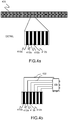
- Figs. 4a and 4b are schematic detailed illustrations of an exemplary head band 400 , which is an example of the head band 310 , in accordance with an embodiment of the present disclosure.
- the head band 400 includes one or more conducting stripes 410a and 410b separated by one or more insulating stripes 412a and 412b , hereinafter collectively referred to as stripes.
- the head band 400 is made from a zebra connector type of material.
- the control logic 420 which is an example of the control logic 312 , is connected to each stripe separately through wires 422 and controls each stripe separately. In some embodiments, the control logic 420 may be connected to two or more stripes together and controls a group of stripes together. The control logic 420 further sets the polarity of each stripe to be positive, negative or floating, thus configuring each stripe either as a cathode element or an anode element. After the stripes are configured as cathode/anode elements, they may be used for transcranial stimulation of the head region of the user.
- Fig. 4c is a schematic illustration of a one-dimensional array 430 of electrode elements A, B, C and D formed from conducting stripes 410a , 410b , 410c and 410d , in accordance with an embodiment of the present disclosure.
- the electrode elements may include anode as well as cathode elements, and may be controlled by the control logic 420.
- the control logic 420 is configured to measure current and voltage fed via/from the electrode elements A, B, C and D, and measure a resistance and/or impedance between at least one pair of electrode elements based on the measured current and voltages.
- control logic 420 may be configured to measure resistances R ab , R ac , R ad , R bc , R bd , R ed between each possible pair of the electrode elements A, B, C and D.
- the control logic 420 concludes that the electrode elements A, B, C and D may provide substantially equal amount of conductivity to the head region of the subject.
- Fig. 4d is a schematic illustration of a two-dimensional array 440 of electrode elements A till L, in accordance with an embodiment of the present disclosure.
- One or more conducting stripes of the head band 400 may be arranged in a manner so as to form the two-dimensional array 440 of the electrode elements A till L.
- resistances and/or impedances between substantially all combinations of the electrode elements A till L may be measured to determine quality of the conductivity to the head region of the subject.
- Figs. 4a-4d are merely examples, which should not unduly limit the scope of the claims herein.
- Fig. 5 is an illustration of steps of a method of using a system for transcranial stimulation of a head region of a subject, in accordance with the present disclosure; it will be appreciated that such transcranial stimulation is not limited to methods of treatment of the animal or human body, but can be for other purposes also, for example for relieving stress, for relaxation, for comfort and so forth.
- the method is depicted as a collection of steps in a logical flow diagram, which represents a sequence of steps that can be implemented in hardware, software, or a combination thereof.
- an electrode arrangement comprising a plurality of electrodes 202 and 204 coupled to at least one electrode drive arrangement 206 is attached onto skin of the head region of the subject.
- the electrode 202 is arranged to include first through ninth electrode elements C 1 till C 9
- another electrode 204 is arranged to include tenth through fifteenth electrode elements C 10 till C 15 , which are operable in combination to deliver a current of their corresponding at least one electrode 202/204 to the head region of the subject.
- At a step 506 at least one electrode drive arrangement 206 is used to excite and/or monitor the first through fifteenth electrode elements C1 till C15 in an individually controlled and/or monitored manner.
- steps 502 to 506 are only illustrative.
- Fig. 5 is merely an example.
- Embodiments are not limited to direct current transcranial stimulation. Based on embodiments, conductivity between electrodes can also be verified, for example for transcranial alternative current stimulation (tACS), transcranial alternative current stimulation (tACS), transcranial random noise stimulation (tRNS) and transcutaneous electrical nerve stimulation (TENS).
- tACS transcranial alternative current stimulation
- tACS transcranial alternative current stimulation
- tRNS transcranial random noise stimulation
- TNS transcutaneous electrical nerve stimulation
Landscapes
- Health & Medical Sciences (AREA)
- Life Sciences & Earth Sciences (AREA)
- Animal Behavior & Ethology (AREA)
- Nuclear Medicine, Radiotherapy & Molecular Imaging (AREA)
- Radiology & Medical Imaging (AREA)
- Biomedical Technology (AREA)
- General Health & Medical Sciences (AREA)
- Public Health (AREA)
- Veterinary Medicine (AREA)
- Engineering & Computer Science (AREA)
- Heart & Thoracic Surgery (AREA)
- Biophysics (AREA)
- Neurology (AREA)
- Psychology (AREA)
- Psychiatry (AREA)
- Hospice & Palliative Care (AREA)
- Social Psychology (AREA)
- Developmental Disabilities (AREA)
- Child & Adolescent Psychology (AREA)
- Neurosurgery (AREA)
- Cardiology (AREA)
- Electrotherapy Devices (AREA)
Claims (4)
- System (100, 200) zur transkraniellen Stimulation einer Person, wobei das System (100, 200) einschließt- eine Steueranordnung (102, 206, 312, 420);- eine Elektrodenanordnung, die eine Vielzahl von Elektroden (202, 204, 400) umfasst, die mit mindestens einer Elektrodenantriebsanordnung gekoppelt sind, wobei die Vielzahl von Elektroden (202, 204) dafür betreibbar sind, um auf der Haut des Kopfbereichs (110, 300) der Person zu kontaktieren,dadurch gekennzeichnet, dass mindestens eine der Vielzahl von Elektroden (202, 204) eine Vielzahl von Elektrodenelementen (C1, C2, C3, C4, C5, C6, C7, C8, C9, C10, C11, C12, C13, C14, C15, 410a, 410b, 412a, 412b) umfasst, die in Kombination dafür betreibbar sind, um einen Strom ihrer entsprechenden mindestens einen Elektrode (202, 204, 400) an den Kopfbereich (110, 300) der Person zu liefern und wobei die mindestens eine Elektrodenantriebsanordnung dafür angeordnet ist, um im Betrieb die Elektrodenelemente (C1, C2, C3, C4, C5, C6, C7, C8, C9, C10, C11, C12, C13, C14, C15, 410a, 410b, 412a, 412b) auf eine individuell gesteuerte und überwachte Weise anzuregen und zu überwachen, und die mindestens eine Elektrodenantriebsanordnung dafür betreibbar ist, um im Wesentlichen eine Stromverteilung zwischen der Vielzahl von Elektrodenelementen (C1, C2, C3, C4, C5, C6, C7, C8, C9, C10, C11, C12, C13, C14, C15, 410a, 410b, 412a, 412b) der mindestens einen Elektrode (202, 204) bei Kontakt mit der Haut des Kopfbereichs (110, 300) der Person auszugleichen, wobei die Steueranordnung (102, 206, 312, 420) dafür konfiguriert ist, um vor Beginnen von transkranieller Stimulation des Kopfbereichs (110, 300) der Person bei Kontakt mit der Haut der Person Leitfähigkeits- und/oder Impedanztests der Vielzahl von Elektroden (202, 204) und der Vielzahl von Elektrodenelementen (C1, C2, C3, C4, C5, C6, C7, C8, C9, C10, C11, C12, C13, C14, C15, 410a, 410b, 412a, 412b) durchzuführen.
- System (100, 200) nach Anspruch 1, wobei die Vielzahl von Elektrodenelementen (C1, C2, C3, C4, C5, C6, C7, C8, C9, C10, C11, C12, C13, C14, C15, 410a, 410b, 412a, 412b) der Elektroden (202, 204, 400) in einer zweidimensionalen Array-Konfiguration angebracht sind, wenn sie bei Betrieb auf den Kopf der Person eingreifen.
- System (100, 200) nach Anspruch 1, wobei die mehreren Elektrodenelemente (C1, C2, C3, C4, C5, C6, C7, C8, C9, C10, C11, C12, C13, C14, C15, 410a, 410b, 412a, 412b) der Elektroden (202, 204, 400) in einer eindimensionalen Array-Konfiguration (400) angebracht sind, wenn sie bei Betrieb auf den Kopf der Person eingreifen.
- System (100, 200) nach einem der vorstehenden Ansprüche, wobei die mindestens eine Elektrodenantriebsanordnung dafür betreibbar ist, um im Wesentlichen die Stromverteilung zwischen der Vielzahl von Elektrodenelementen (C1, C2, C3, C4, C5, C6, C7, C8, C9, C10, C11, C12, C13, C14, C15, 410a, 410b, 412a, 412b) der mindestens einen Elektrode (202, 204, 400) bei Kontakt mit der Haut des Kopfbereichs (110, 300) der Person auf innerhalb einer Variation von weniger als 50 %, mehr bevorzugt weniger als 20 % und am meisten bevorzugt weniger als 10 % auszugleichen.
Applications Claiming Priority (2)
| Application Number | Priority Date | Filing Date | Title |
|---|---|---|---|
| GB1406050.3A GB2524816B (en) | 2014-04-03 | 2014-04-03 | System and method for transcranial stimulation of a subject |
| PCT/FI2015/050211 WO2015150625A1 (en) | 2014-04-03 | 2015-03-27 | System and method for transcranial stimulation of a subject |
Publications (2)
| Publication Number | Publication Date |
|---|---|
| EP3125993A1 EP3125993A1 (de) | 2017-02-08 |
| EP3125993B1 true EP3125993B1 (de) | 2021-05-05 |
Family
ID=50776798
Family Applications (1)
| Application Number | Title | Priority Date | Filing Date |
|---|---|---|---|
| EP15717944.1A Active EP3125993B1 (de) | 2014-04-03 | 2015-03-27 | System zur transkranialen stimulation einer person |
Country Status (4)
| Country | Link |
|---|---|
| US (1) | US20170151430A1 (de) |
| EP (1) | EP3125993B1 (de) |
| GB (1) | GB2524816B (de) |
| WO (1) | WO2015150625A1 (de) |
Families Citing this family (17)
| Publication number | Priority date | Publication date | Assignee | Title |
|---|---|---|---|---|
| EP3038700B1 (de) | 2013-08-27 | 2020-03-11 | Halo Neuro, Inc. | Verfahren und system zur bereitstellung einer elektrischer stimulation an einen benutzer |
| US9782585B2 (en) | 2013-08-27 | 2017-10-10 | Halo Neuro, Inc. | Method and system for providing electrical stimulation to a user |
| US20180001107A1 (en) | 2016-07-01 | 2018-01-04 | Btl Holdings Limited | Aesthetic method of biological structure treatment by magnetic field |
| US10695575B1 (en) | 2016-05-10 | 2020-06-30 | Btl Medical Technologies S.R.O. | Aesthetic method of biological structure treatment by magnetic field |
| EP3413966A4 (de) * | 2016-02-08 | 2019-11-27 | Halo Neuro, Inc. | Verfahren und system zur verbesserung der bereitstellung von elektrischer stimulation |
| EP3589356B1 (de) | 2016-04-11 | 2023-07-26 | Monash University | Transkranielle stimulation mit echtzeitüberwachung |
| US11464993B2 (en) | 2016-05-03 | 2022-10-11 | Btl Healthcare Technologies A.S. | Device including RF source of energy and vacuum system |
| CN110234389B (zh) | 2017-02-02 | 2023-11-03 | 福禄神经学公司 | 用于经颅直流电刺激tdcs的头戴设备和包括头戴设备的系统 |
| RU176302U1 (ru) * | 2017-03-13 | 2018-01-16 | Федеральное государственное бюджетное образовательное учреждение высшего образования "Амурская государственная медицинская академия" Министерства здравоохранения Российской Федерации | Устройство для транскраниальной стимуляции головного мозга постоянным током |
| US10507324B2 (en) | 2017-11-17 | 2019-12-17 | Halo Neuro, Inc. | System and method for individualizing modulation |
| CN108671390A (zh) * | 2018-05-07 | 2018-10-19 | 南京沃高医疗科技有限公司 | 具有高精度定位输出功能的电刺激装置 |
| EP3603737B1 (de) | 2018-07-31 | 2020-08-26 | Flow Neuroscience AB | Positionierung von elektroden zur transkranialen stimulation des gehirns |
| US12558146B2 (en) | 2019-04-11 | 2026-02-24 | Btl Medical Solutions A.S. | Methods and devices for aesthetic treatment of biological structures by radiofrequency and magnetic energy |
| US12611545B2 (en) | 2020-05-04 | 2026-04-28 | Btl Healthcare Technologies A.S. | Device and method for unattended treatment of a patient |
| US11878167B2 (en) | 2020-05-04 | 2024-01-23 | Btl Healthcare Technologies A.S. | Device and method for unattended treatment of a patient |
| ES2993637T3 (en) | 2020-05-04 | 2025-01-03 | Btl Healthcare Technologies As | Device for unattended treatment of a patient |
| US20260097227A1 (en) | 2024-10-08 | 2026-04-09 | Btl Medical Solutions A.S. | Devices and methods for application of a magnetic field to the nervous system |
Family Cites Families (9)
| Publication number | Priority date | Publication date | Assignee | Title |
|---|---|---|---|---|
| WO2002087410A2 (en) * | 2001-04-27 | 2002-11-07 | Yacov Naisberg | Diagnosis, treatment and research of mental disorders |
| WO2009090682A1 (en) * | 2008-01-15 | 2009-07-23 | Christian Falconi | Stimulation device |
| WO2009137683A2 (en) * | 2008-05-07 | 2009-11-12 | Hoffman Ross G | Transcranial direct current stimulation apparatus and methods |
| US9440063B2 (en) * | 2008-12-30 | 2016-09-13 | Research Foundation Od The City University Of New York | Methods for reducing discomfort during electrostimulation, and compositions and apparatus therefor |
| EP2419172A4 (de) * | 2009-04-13 | 2014-03-12 | Univ City New York Res Found | Transkranielle stimulation |
| DE102011120213A1 (de) * | 2010-12-28 | 2012-06-28 | Ebs Technologies Gmbh | Vorrichtung zur nicht-invasiven, elektrischen Tiefenhirnstimulation |
| US20130204315A1 (en) * | 2011-08-05 | 2013-08-08 | Ndi Medical, Llc | Systems for and methods of transcranial direct current electrical stimulation |
| CN102698360A (zh) * | 2012-04-21 | 2012-10-03 | 南京理工大学 | 一种高聚焦性多通道经颅直流电刺激装置和控制方法 |
| US9339642B1 (en) * | 2013-03-13 | 2016-05-17 | Soterix Medical, Inc. | System and method for conducting multi-electrode electrical stimulation |
-
2014
- 2014-04-03 GB GB1406050.3A patent/GB2524816B/en active Active
-
2015
- 2015-03-27 EP EP15717944.1A patent/EP3125993B1/de active Active
- 2015-03-27 US US15/300,079 patent/US20170151430A1/en not_active Abandoned
- 2015-03-27 WO PCT/FI2015/050211 patent/WO2015150625A1/en not_active Ceased
Also Published As
| Publication number | Publication date |
|---|---|
| US20170151430A1 (en) | 2017-06-01 |
| WO2015150625A1 (en) | 2015-10-08 |
| GB2524816B (en) | 2016-03-30 |
| GB2524816A (en) | 2015-10-07 |
| GB201406050D0 (en) | 2014-05-21 |
| EP3125993A1 (de) | 2017-02-08 |
Similar Documents
| Publication | Publication Date | Title |
|---|---|---|
| US20170151430A1 (en) | System and method for transcranial stimulation of a subject | |
| US11857786B2 (en) | Method and device for transdermally applying electrical stimulation to a region of the head having high impedance | |
| US12144987B2 (en) | Methods and apparatuses for transdermal stimulation of the outer ear | |
| US10426945B2 (en) | Methods and apparatuses for transdermal stimulation of the outer ear | |
| US20200297999A1 (en) | Systems and methods for applying electrical energy to treat psoriasis | |
| US9415220B1 (en) | Auricular stimulation for inflammatory parasympathetic diseases | |
| US20130204315A1 (en) | Systems for and methods of transcranial direct current electrical stimulation | |
| EP4013485B1 (de) | Verfahren zur transdermalen neurostimulationsbehandlung | |
| JP2021514208A (ja) | 皮膚用指先取付微小電流装置 | |
| US12257392B1 (en) | Systems and methods for meditation enhancement | |
| WO2017108058A1 (en) | Transcranial electrical stimulation device having multipurpose electrodes | |
| CN106573138A (zh) | 用于神经刺激的用户控制的方法和装置 | |
| CN117462844A (zh) | 用于经颅直流电刺激tdcs的头戴设备和包括头戴设备的系统 | |
| KR102135944B1 (ko) | 마스크 시트의 동적 이온 토포레시스 수행 장치 | |
| JP2023041660A (ja) | 装置および装置の製造方法 | |
| CN109316661A (zh) | 一种用于疼痛治疗的便携式经颅直流电刺激系统 | |
| CN119905214A (zh) | 刺激电场显示方法、装置、系统、设备、介质及产品 | |
| HK1228819B (zh) | 用於改变或诱导认知状态的经皮电刺激设备和方法 |
Legal Events
| Date | Code | Title | Description |
|---|---|---|---|
| STAA | Information on the status of an ep patent application or granted ep patent |
Free format text: STATUS: THE INTERNATIONAL PUBLICATION HAS BEEN MADE |
|
| PUAI | Public reference made under article 153(3) epc to a published international application that has entered the european phase |
Free format text: ORIGINAL CODE: 0009012 |
|
| STAA | Information on the status of an ep patent application or granted ep patent |
Free format text: STATUS: REQUEST FOR EXAMINATION WAS MADE |
|
| 17P | Request for examination filed |
Effective date: 20160919 |
|
| AK | Designated contracting states |
Kind code of ref document: A1 Designated state(s): AL AT BE BG CH CY CZ DE DK EE ES FI FR GB GR HR HU IE IS IT LI LT LU LV MC MK MT NL NO PL PT RO RS SE SI SK SM TR |
|
| AX | Request for extension of the european patent |
Extension state: BA ME |
|
| DAV | Request for validation of the european patent (deleted) | ||
| DAX | Request for extension of the european patent (deleted) | ||
| GRAP | Despatch of communication of intention to grant a patent |
Free format text: ORIGINAL CODE: EPIDOSNIGR1 |
|
| STAA | Information on the status of an ep patent application or granted ep patent |
Free format text: STATUS: GRANT OF PATENT IS INTENDED |
|
| INTG | Intention to grant announced |
Effective date: 20210114 |
|
| GRAS | Grant fee paid |
Free format text: ORIGINAL CODE: EPIDOSNIGR3 |
|
| GRAA | (expected) grant |
Free format text: ORIGINAL CODE: 0009210 |
|
| STAA | Information on the status of an ep patent application or granted ep patent |
Free format text: STATUS: THE PATENT HAS BEEN GRANTED |
|
| AK | Designated contracting states |
Kind code of ref document: B1 Designated state(s): AL AT BE BG CH CY CZ DE DK EE ES FI FR GB GR HR HU IE IS IT LI LT LU LV MC MK MT NL NO PL PT RO RS SE SI SK SM TR |
|
| REG | Reference to a national code |
Ref country code: GB Ref legal event code: FG4D |
|
| REG | Reference to a national code |
Ref country code: CH Ref legal event code: EP |
|
| REG | Reference to a national code |
Ref country code: AT Ref legal event code: REF Ref document number: 1389039 Country of ref document: AT Kind code of ref document: T Effective date: 20210515 |
|
| REG | Reference to a national code |
Ref country code: DE Ref legal event code: R096 Ref document number: 602015068940 Country of ref document: DE |
|
| REG | Reference to a national code |
Ref country code: IE Ref legal event code: FG4D |
|
| REG | Reference to a national code |
Ref country code: LT Ref legal event code: MG9D |
|
| REG | Reference to a national code |
Ref country code: AT Ref legal event code: MK05 Ref document number: 1389039 Country of ref document: AT Kind code of ref document: T Effective date: 20210505 |
|
| PG25 | Lapsed in a contracting state [announced via postgrant information from national office to epo] |
Ref country code: FI Free format text: LAPSE BECAUSE OF FAILURE TO SUBMIT A TRANSLATION OF THE DESCRIPTION OR TO PAY THE FEE WITHIN THE PRESCRIBED TIME-LIMIT Effective date: 20210505 Ref country code: LT Free format text: LAPSE BECAUSE OF FAILURE TO SUBMIT A TRANSLATION OF THE DESCRIPTION OR TO PAY THE FEE WITHIN THE PRESCRIBED TIME-LIMIT Effective date: 20210505 Ref country code: HR Free format text: LAPSE BECAUSE OF FAILURE TO SUBMIT A TRANSLATION OF THE DESCRIPTION OR TO PAY THE FEE WITHIN THE PRESCRIBED TIME-LIMIT Effective date: 20210505 Ref country code: AT Free format text: LAPSE BECAUSE OF FAILURE TO SUBMIT A TRANSLATION OF THE DESCRIPTION OR TO PAY THE FEE WITHIN THE PRESCRIBED TIME-LIMIT Effective date: 20210505 Ref country code: BG Free format text: LAPSE BECAUSE OF FAILURE TO SUBMIT A TRANSLATION OF THE DESCRIPTION OR TO PAY THE FEE WITHIN THE PRESCRIBED TIME-LIMIT Effective date: 20210805 |
|
| PG25 | Lapsed in a contracting state [announced via postgrant information from national office to epo] |
Ref country code: IS Free format text: LAPSE BECAUSE OF FAILURE TO SUBMIT A TRANSLATION OF THE DESCRIPTION OR TO PAY THE FEE WITHIN THE PRESCRIBED TIME-LIMIT Effective date: 20210905 Ref country code: GR Free format text: LAPSE BECAUSE OF FAILURE TO SUBMIT A TRANSLATION OF THE DESCRIPTION OR TO PAY THE FEE WITHIN THE PRESCRIBED TIME-LIMIT Effective date: 20210806 Ref country code: LV Free format text: LAPSE BECAUSE OF FAILURE TO SUBMIT A TRANSLATION OF THE DESCRIPTION OR TO PAY THE FEE WITHIN THE PRESCRIBED TIME-LIMIT Effective date: 20210505 Ref country code: RS Free format text: LAPSE BECAUSE OF FAILURE TO SUBMIT A TRANSLATION OF THE DESCRIPTION OR TO PAY THE FEE WITHIN THE PRESCRIBED TIME-LIMIT Effective date: 20210505 Ref country code: SE Free format text: LAPSE BECAUSE OF FAILURE TO SUBMIT A TRANSLATION OF THE DESCRIPTION OR TO PAY THE FEE WITHIN THE PRESCRIBED TIME-LIMIT Effective date: 20210505 Ref country code: ES Free format text: LAPSE BECAUSE OF FAILURE TO SUBMIT A TRANSLATION OF THE DESCRIPTION OR TO PAY THE FEE WITHIN THE PRESCRIBED TIME-LIMIT Effective date: 20210505 Ref country code: PT Free format text: LAPSE BECAUSE OF FAILURE TO SUBMIT A TRANSLATION OF THE DESCRIPTION OR TO PAY THE FEE WITHIN THE PRESCRIBED TIME-LIMIT Effective date: 20210906 Ref country code: PL Free format text: LAPSE BECAUSE OF FAILURE TO SUBMIT A TRANSLATION OF THE DESCRIPTION OR TO PAY THE FEE WITHIN THE PRESCRIBED TIME-LIMIT Effective date: 20210505 Ref country code: NO Free format text: LAPSE BECAUSE OF FAILURE TO SUBMIT A TRANSLATION OF THE DESCRIPTION OR TO PAY THE FEE WITHIN THE PRESCRIBED TIME-LIMIT Effective date: 20210805 |
|
| REG | Reference to a national code |
Ref country code: NL Ref legal event code: MP Effective date: 20210505 |
|
| PG25 | Lapsed in a contracting state [announced via postgrant information from national office to epo] |
Ref country code: NL Free format text: LAPSE BECAUSE OF FAILURE TO SUBMIT A TRANSLATION OF THE DESCRIPTION OR TO PAY THE FEE WITHIN THE PRESCRIBED TIME-LIMIT Effective date: 20210505 |
|
| PG25 | Lapsed in a contracting state [announced via postgrant information from national office to epo] |
Ref country code: EE Free format text: LAPSE BECAUSE OF FAILURE TO SUBMIT A TRANSLATION OF THE DESCRIPTION OR TO PAY THE FEE WITHIN THE PRESCRIBED TIME-LIMIT Effective date: 20210505 Ref country code: CZ Free format text: LAPSE BECAUSE OF FAILURE TO SUBMIT A TRANSLATION OF THE DESCRIPTION OR TO PAY THE FEE WITHIN THE PRESCRIBED TIME-LIMIT Effective date: 20210505 Ref country code: DK Free format text: LAPSE BECAUSE OF FAILURE TO SUBMIT A TRANSLATION OF THE DESCRIPTION OR TO PAY THE FEE WITHIN THE PRESCRIBED TIME-LIMIT Effective date: 20210505 Ref country code: SK Free format text: LAPSE BECAUSE OF FAILURE TO SUBMIT A TRANSLATION OF THE DESCRIPTION OR TO PAY THE FEE WITHIN THE PRESCRIBED TIME-LIMIT Effective date: 20210505 Ref country code: SM Free format text: LAPSE BECAUSE OF FAILURE TO SUBMIT A TRANSLATION OF THE DESCRIPTION OR TO PAY THE FEE WITHIN THE PRESCRIBED TIME-LIMIT Effective date: 20210505 Ref country code: RO Free format text: LAPSE BECAUSE OF FAILURE TO SUBMIT A TRANSLATION OF THE DESCRIPTION OR TO PAY THE FEE WITHIN THE PRESCRIBED TIME-LIMIT Effective date: 20210505 |
|
| REG | Reference to a national code |
Ref country code: DE Ref legal event code: R097 Ref document number: 602015068940 Country of ref document: DE |
|
| PLBE | No opposition filed within time limit |
Free format text: ORIGINAL CODE: 0009261 |
|
| STAA | Information on the status of an ep patent application or granted ep patent |
Free format text: STATUS: NO OPPOSITION FILED WITHIN TIME LIMIT |
|
| 26N | No opposition filed |
Effective date: 20220208 |
|
| PG25 | Lapsed in a contracting state [announced via postgrant information from national office to epo] |
Ref country code: IS Free format text: LAPSE BECAUSE OF FAILURE TO SUBMIT A TRANSLATION OF THE DESCRIPTION OR TO PAY THE FEE WITHIN THE PRESCRIBED TIME-LIMIT Effective date: 20210905 Ref country code: AL Free format text: LAPSE BECAUSE OF FAILURE TO SUBMIT A TRANSLATION OF THE DESCRIPTION OR TO PAY THE FEE WITHIN THE PRESCRIBED TIME-LIMIT Effective date: 20210505 |
|
| PG25 | Lapsed in a contracting state [announced via postgrant information from national office to epo] |
Ref country code: IT Free format text: LAPSE BECAUSE OF FAILURE TO SUBMIT A TRANSLATION OF THE DESCRIPTION OR TO PAY THE FEE WITHIN THE PRESCRIBED TIME-LIMIT Effective date: 20210505 |
|
| PG25 | Lapsed in a contracting state [announced via postgrant information from national office to epo] |
Ref country code: MC Free format text: LAPSE BECAUSE OF FAILURE TO SUBMIT A TRANSLATION OF THE DESCRIPTION OR TO PAY THE FEE WITHIN THE PRESCRIBED TIME-LIMIT Effective date: 20210505 |
|
| REG | Reference to a national code |
Ref country code: CH Ref legal event code: PL |
|
| REG | Reference to a national code |
Ref country code: BE Ref legal event code: MM Effective date: 20220331 |
|
| PG25 | Lapsed in a contracting state [announced via postgrant information from national office to epo] |
Ref country code: LU Free format text: LAPSE BECAUSE OF NON-PAYMENT OF DUE FEES Effective date: 20220327 Ref country code: LI Free format text: LAPSE BECAUSE OF NON-PAYMENT OF DUE FEES Effective date: 20220331 Ref country code: IE Free format text: LAPSE BECAUSE OF NON-PAYMENT OF DUE FEES Effective date: 20220327 Ref country code: CH Free format text: LAPSE BECAUSE OF NON-PAYMENT OF DUE FEES Effective date: 20220331 |
|
| PG25 | Lapsed in a contracting state [announced via postgrant information from national office to epo] |
Ref country code: BE Free format text: LAPSE BECAUSE OF NON-PAYMENT OF DUE FEES Effective date: 20220331 |
|
| PG25 | Lapsed in a contracting state [announced via postgrant information from national office to epo] |
Ref country code: HU Free format text: LAPSE BECAUSE OF FAILURE TO SUBMIT A TRANSLATION OF THE DESCRIPTION OR TO PAY THE FEE WITHIN THE PRESCRIBED TIME-LIMIT; INVALID AB INITIO Effective date: 20150327 |
|
| PG25 | Lapsed in a contracting state [announced via postgrant information from national office to epo] |
Ref country code: MK Free format text: LAPSE BECAUSE OF FAILURE TO SUBMIT A TRANSLATION OF THE DESCRIPTION OR TO PAY THE FEE WITHIN THE PRESCRIBED TIME-LIMIT Effective date: 20210505 Ref country code: CY Free format text: LAPSE BECAUSE OF FAILURE TO SUBMIT A TRANSLATION OF THE DESCRIPTION OR TO PAY THE FEE WITHIN THE PRESCRIBED TIME-LIMIT Effective date: 20210505 |
|
| PG25 | Lapsed in a contracting state [announced via postgrant information from national office to epo] |
Ref country code: MT Free format text: LAPSE BECAUSE OF FAILURE TO SUBMIT A TRANSLATION OF THE DESCRIPTION OR TO PAY THE FEE WITHIN THE PRESCRIBED TIME-LIMIT Effective date: 20210505 |
|
| PG25 | Lapsed in a contracting state [announced via postgrant information from national office to epo] |
Ref country code: TR Free format text: LAPSE BECAUSE OF FAILURE TO SUBMIT A TRANSLATION OF THE DESCRIPTION OR TO PAY THE FEE WITHIN THE PRESCRIBED TIME-LIMIT Effective date: 20210505 |
|
| PGFP | Annual fee paid to national office [announced via postgrant information from national office to epo] |
Ref country code: GB Payment date: 20260324 Year of fee payment: 12 |
|
| PGFP | Annual fee paid to national office [announced via postgrant information from national office to epo] |
Ref country code: DE Payment date: 20260319 Year of fee payment: 12 |
|
| PGFP | Annual fee paid to national office [announced via postgrant information from national office to epo] |
Ref country code: FR Payment date: 20260320 Year of fee payment: 12 |