EP3125833B1 - Deployment handle for a medical device deployment system - Google Patents
Deployment handle for a medical device deployment system Download PDFInfo
- Publication number
- EP3125833B1 EP3125833B1 EP15716314.8A EP15716314A EP3125833B1 EP 3125833 B1 EP3125833 B1 EP 3125833B1 EP 15716314 A EP15716314 A EP 15716314A EP 3125833 B1 EP3125833 B1 EP 3125833B1
- Authority
- EP
- European Patent Office
- Prior art keywords
- knob
- handle
- state
- deployment
- actuating
- Prior art date
- Legal status (The legal status is an assumption and is not a legal conclusion. Google has not performed a legal analysis and makes no representation as to the accuracy of the status listed.)
- Active
Links
Images


Classifications
-
- A—HUMAN NECESSITIES
- A61—MEDICAL OR VETERINARY SCIENCE; HYGIENE
- A61F—FILTERS IMPLANTABLE INTO BLOOD VESSELS; PROSTHESES; DEVICES PROVIDING PATENCY TO, OR PREVENTING COLLAPSING OF, TUBULAR STRUCTURES OF THE BODY, e.g. STENTS; ORTHOPAEDIC, NURSING OR CONTRACEPTIVE DEVICES; FOMENTATION; TREATMENT OR PROTECTION OF EYES OR EARS; BANDAGES, DRESSINGS OR ABSORBENT PADS; FIRST-AID KITS
- A61F2/00—Filters implantable into blood vessels; Prostheses, i.e. artificial substitutes or replacements for parts of the body; Appliances for connecting them with the body; Devices providing patency to, or preventing collapsing of, tubular structures of the body, e.g. stents
- A61F2/95—Instruments specially adapted for placement or removal of stents or stent-grafts
- A61F2/9517—Instruments specially adapted for placement or removal of stents or stent-grafts handle assemblies therefor
-
- A—HUMAN NECESSITIES
- A61—MEDICAL OR VETERINARY SCIENCE; HYGIENE
- A61F—FILTERS IMPLANTABLE INTO BLOOD VESSELS; PROSTHESES; DEVICES PROVIDING PATENCY TO, OR PREVENTING COLLAPSING OF, TUBULAR STRUCTURES OF THE BODY, e.g. STENTS; ORTHOPAEDIC, NURSING OR CONTRACEPTIVE DEVICES; FOMENTATION; TREATMENT OR PROTECTION OF EYES OR EARS; BANDAGES, DRESSINGS OR ABSORBENT PADS; FIRST-AID KITS
- A61F2/00—Filters implantable into blood vessels; Prostheses, i.e. artificial substitutes or replacements for parts of the body; Appliances for connecting them with the body; Devices providing patency to, or preventing collapsing of, tubular structures of the body, e.g. stents
- A61F2/95—Instruments specially adapted for placement or removal of stents or stent-grafts
- A61F2/962—Instruments specially adapted for placement or removal of stents or stent-grafts having an outer sleeve
- A61F2/966—Instruments specially adapted for placement or removal of stents or stent-grafts having an outer sleeve with relative longitudinal movement between outer sleeve and prosthesis, e.g. using a push rod
-
- A—HUMAN NECESSITIES
- A61—MEDICAL OR VETERINARY SCIENCE; HYGIENE
- A61B—DIAGNOSIS; SURGERY; IDENTIFICATION
- A61B17/00—Surgical instruments, devices or methods
- A61B17/34—Trocars; Puncturing needles
- A61B17/3403—Needle locating or guiding means
- A61B2017/3405—Needle locating or guiding means using mechanical guide means
- A61B2017/3409—Needle locating or guiding means using mechanical guide means including needle or instrument drives
Definitions
- the present disclosure relates to medical device deployment systems. More particularly, the present disclosure relates to a handle for a medical device deployment system.
- WO 03/068302 discloses a control mechanism for medical catheters comprising an elongate handle having an external thread and a barrel with internally projecting pins threaded over the handle. Rotation of the barrel causes the handle to move back and forth along its longitudinal axis to retract and advance a catheter sheath to which the handle is coupled, thereby enabling an implant to be deployed by the catheter. Rotational movement of the barrel and longitudinal movement of the handle can be dissociated to enable speedy retraction or advancement of the catheter sheath.
- Some aspects of the disclosure are directed to a deployment handle for an introducer assembly for endoluminal delivery of an implantable device, said handle comprising:
- Introducer assemblies for endoluminal delivery of vascular implants in accordance with various embodiments are disclosed for allowing actuation or deployment of a vascular implant, while forcing a particular order of operation of the handle by a clinician.
- an introducer assembly includes a first actuating mechanism for actuating a constraining sheath between a first state releasably constraining a vascular implant and a second state allowing deployment of the vascular implant; a second actuating mechanism for actuating a blocking mechanism between a blocked state for blocking one or more other knobs and/or other functions of the handle and an unblocked state for allowing operation of the one or more other knobs and/or other functions of the handle; and an operating knob operatively coupled to both of the first and second actuating mechanisms for concurrent operation of both of the first and second actuating mechanisms in response to actuation of the operating knob.
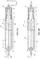
- An example of such an introducer assembly is generally indicated at 100 in FIG 1 .
- the introducer assembly 100 includes a sheath 200 and a handle 300.
- the introducer assembly 100 includes a constraint (not shown) for releasably constraining a vascular implant toward a distal end 210 of the sheath 200.
- the constraint has a first state releasably constraining an expandable implant toward a delivery configuration suitable for endoluminal delivery, and a second state released to allow expansion of the implant from the delivery configuration toward a deployed configuration.
- the handle includes an actuating member operatively coupled to the constraint for actuating the constraint between the first state and the second state.
- the constraint can include a film sleeve that extends around the implant.
- opposite portions or edges of the film sleeve can be releasably held or sewn together by an elongated member, such as a wire or fiber, to maintain the implant in the delivery configuration.
- the sleeve can be opened, or otherwise disrupted, by displacing, unstitching or otherwise disengaging the elongated member from the film sleeve to allow expansion of the implant.
- Further details of such constraining sleeves can be found, for example, U.S. Pat. No. 6,352,561 issued to Leopold, et al. , and U.S. Pat. No. 6,551,350 issued to Thornton, et al. .
- the actuating member can be coupled to the elongated member to release or open the film sleeve from the first state to the second state.
- the constraint can include an axially displaceable tube, wherein such a tube can be formed from a wrapped film tube or an extruded polymer.
- the sheath itself could be such a constraint, wherein the sheath in the first state extends over the implant to retain the implant toward the delivery configuration. The sheath can be displaced toward the second state to allow expansion of the implant from the delivery configuration.
- the actuating member can be coupled to the sheath so that the sheath is displaced with the actuating member between the first state and second state.
- the actuating member can be configured for deploying an implant from either type of constraint described above, or other similarly actuated constraint mechanisms known in the art.
- the latter type of integrated sheath and constraint are described below in connection with the illustrated embodiments.
- the handle 300 includes an actuating member 310 coupled to the sheath 200 for actuating the sheath 200 between the first state and second state in response to linear displacement of the actuating member 310 between a first position and a second position, respectively.
- the handle 300 includes a first actuating mechanism 320 for displacing the actuating member 310 between the first position and the second position.
- the handle 300 includes a main knob 330 for operating the first actuating mechanism 320. Described further below, the handle 300 can include one or more additional knobs to operate one or more additional separate handle functions.
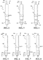
- the handle 300 includes a cover 350 operable for movement between a covered state covering the one or more additional knobs 340, 342, 344 as shown in FIGS. 9A and 9B , and an uncovered state allowing access to the one or more additional knobs 340, 342, 344 as shown in FIGS. 9C and 9D .
- the handle 300 includes a second actuating mechanism 360 for displacing the cover 350 between the covered state and the uncovered state.
- the main knob 330 is operatively coupled to both of the first actuating mechanism 320 and the second actuating mechanism 360 to cause displacement of both the actuating member 310 between the first state and the second state and the cover 350 between the covered state and the uncovered state, respectively, in response to corresponding operation of the main knob 330.
- an actuating knob of the handle can be configured for rotation about an axis
- an actuating member for actuating one or more functions of the handle can be configured for displacement along and/or about the axis between operating states in response to corresponding rotation of the actuating knob.
- the main knob 330 is rotatable about a rotational axis 332.
- the actuating member 310 is movable linearly along the axis 332 between the first state and second state.
- the first actuating mechanism 320 includes a first helical guide 322 movable with the main knob 330 about the axis 332.
- the first actuating mechanism 320 includes a first follower 324 on the actuating member 310 engaged with the first helical guide 322 to cause linear movement of the actuating member 310 between the first state and second state in response to corresponding rotation of the main knob 330.
- the main knob 330 includes a receiving tube 334 receiving at least a portion of the actuating member 310 therethrough as the actuating member 310 moves between the first state and second state.
- the first helical guide 322 is a first helical slot 326 formed along an inner surface 336 of the receiving tube 334 and the first follower 324 includes an outwardly extending first pin 338 engaged with the helical slot 326.
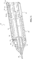
- the second actuating mechanism 360 includes a second helical guide 362 that translates rotation of the main knob 330 to axial displacement of the cover 350.
- the second helical guide 362 comprises a second helical slot 368 formed along an outer surface of a spindle 364, the spindle 364 being aligned with the axis 332 ( FIG. 9A-9D ) of the main knob 330.
- the second actuating mechanism 360 also includes a longitudinal slot 366 formed along the main knob 330. In various embodiments, the slot 366 is parallel with the axis 332 of the main knob 330.
- the second actuating mechanism 360 includes a second pin 363 extending from the cover 350 and slidably engaged with the longitudinal slot 366. As best shown in FIG. 13 , the second actuating mechanism 360 includes a third pin 352 extending from the cover 350 and engaging the second helical slot 368 to cause displacement of the cover 350 between the covered state and the uncovered state in response to corresponding rotation of the main knob 330.
- the actuating mechanisms of the handle can be configured so that functions, such as displacements of the actuating member and cover, are delayed or accelerated relative to each other during operation of the main knob.
- the first helical guide can include a flat or reduced or increased pitch to cause a delay, decrease or increase, respectively, in the displacement of the actuating mechanism relative to the cover in response to operation of the main knob.
- the handle can include a ratchet mechanism that allows actuation of an actuating knob in a first direction and prevents rotation of the actuating knob in an opposite second direction.
- the handle can include a ratchet mechanism having a gear rack on the main knob and a fixed pawl that engages the gear rack to allow rotation of the main knob in a first direction as the pawl slips along teeth of the gear rack and that limits rotation of the main knob in an opposite second direction as the pawl catches a tooth on the gear rack.
- the pawl can be a spring-loaded machined component or alternatively, the pawl can be formed from spring leaf metal.
- the pawl can be configured to generate audible noise and/or at least provide tactile feedback as the pawl slips along the teeth of the gear rack.
- one or more of the teeth of the gear rack can be sized and/or shaped differently from the other teeth of the gear rack to cause a distinct change in sound, e.g. pitch, or tactile feedback, e.g. clicks, resistance, that indicates to a clinician when a certain step in the deployment is achieved.
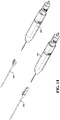
- rotation of the main knob 330 about the axis 332 simultaneously operates the first actuating mechanism 320 to cause displacement of the actuating member 310 in a first direction, as indicated at arrow "a” in FIG. 2 , and the second actuating mechanism 360 to cause displacement of the cover 350 in a second direction, as indicated at arrow "b” in FIG. 2 .
- Displacement of the actuating member 310 in the first direction "a” causes corresponding displacement of the sheath 200 to allow expansion of the expandable implant 400 outwardly from the delivery configuration.
- the expandable vascular implant can be a self-expanding stent graft or, alternatively, a balloon-expanded implant.
- Displacement of the cover 350 in the second direction "b" can reveal one or more additional knobs each for operating one or more other handle functions.
- a second knob 340 is revealed after displacement of the cover 350 for operating a constraining mechanism for selectively constraining at least a portion of the implant to allow positioning of the device prior to committing to a full deployment of the implant at the treatment site.
- a constraining mechanism for selectively constraining at least a portion of the implant to allow positioning of the device prior to committing to a full deployment of the implant at the treatment site.
- the handle can be configured so that the cover can be displaced in steps to reveal additional knobs each for operating one or more other handle functions.
- the third knob 342 can be configured to actuate one or more other handle functions, such as displacing fibers, wires, levers, gears or any combination thereof of a steering mechanism (not shown) for selectively bending or otherwise steering at least a portion of the implant 400 during deployment.
- a release mechanism can include a lock wire frictionally engaged with the implant to maintain a releasable coupling between the implant and the handle.
- the lock wire can be operatively coupled to the fourth knob to be displaced relative to and disengaged from the implant in response to actuation of the fourth knob.
- the lock wire can be wound about a spindle portion of the fourth knob during rotation of the fourth knob. Winding of the lock wire about the spindle displaces the lock wire relative to the implant until the lock wire disengages from the implant.
- handle functions such as steering, reconstraining, and deploying of an expandable implant can be operated by actuating the one or more knobs of the handle, while maintaining the implant at an intermediate configuration within a secondary or intermediate sheath or sleeve, wherein the intermediate configuration is larger than the delivery configuration and smaller than a deployed configuration.
- the introducer assembly can include a secondary sheath for limiting expansion of the implant to an intermediate configuration after displacement of the constraining sheath.
- the secondary sheath can include a flexible film constraining sleeve that extends over and releasably constrains the implant.
- An elongated coupling member such as a fiber or wire, stitches opposing edges or sides of the constraining sleeve together to releasably constrain the implant toward the intermediate configuration.
- the constraining sleeve can be opened by de-coupling the coupling member from the constraining sleeve. Further details of materials and general construction of constraining sleeves can be found in US 6,352,561 to Leopold et al .
- the sheath 200 and handle 300 can be releasably coupled to each other for subsequent re-use of the sheath 200 as an introducer for other surgical implements after deployment of the device and de-coupling of the handle from the introducer.
- the introducer and handle can be threaded or keyed with a slot-pin arrangement to form a releasable coupling that allows separation of the handle after deployment of the device and subsequent re-use or re-purposing of the introducer for introducing other surgical implements, such as other devices, tools, probes, cameras, drugs and saline.
Landscapes
- Health & Medical Sciences (AREA)
- Engineering & Computer Science (AREA)
- Biomedical Technology (AREA)
- Life Sciences & Earth Sciences (AREA)
- Oral & Maxillofacial Surgery (AREA)
- Transplantation (AREA)
- Heart & Thoracic Surgery (AREA)
- Vascular Medicine (AREA)
- Cardiology (AREA)
- Animal Behavior & Ethology (AREA)
- General Health & Medical Sciences (AREA)
- Public Health (AREA)
- Veterinary Medicine (AREA)
- Prostheses (AREA)
- Surgical Instruments (AREA)
- Media Introduction/Drainage Providing Device (AREA)
Priority Applications (1)
| Application Number | Priority Date | Filing Date | Title |
|---|---|---|---|
| EP22204832.4A EP4169490A1 (en) | 2014-04-04 | 2015-03-27 | Deployment handle for a medical device deployment system |
Applications Claiming Priority (3)
| Application Number | Priority Date | Filing Date | Title |
|---|---|---|---|
| US201461975165P | 2014-04-04 | 2014-04-04 | |
| US14/670,234 US9833346B2 (en) | 2014-04-04 | 2015-03-26 | Deployment handle for a medical device deployment system |
| PCT/US2015/023140 WO2015153375A1 (en) | 2014-04-04 | 2015-03-27 | Deployment handle for a medical device deployment system |
Related Child Applications (1)
| Application Number | Title | Priority Date | Filing Date |
|---|---|---|---|
| EP22204832.4A Division EP4169490A1 (en) | 2014-04-04 | 2015-03-27 | Deployment handle for a medical device deployment system |
Publications (2)
| Publication Number | Publication Date |
|---|---|
| EP3125833A1 EP3125833A1 (en) | 2017-02-08 |
| EP3125833B1 true EP3125833B1 (en) | 2022-11-30 |
Family
ID=54208735
Family Applications (2)
| Application Number | Title | Priority Date | Filing Date |
|---|---|---|---|
| EP15716314.8A Active EP3125833B1 (en) | 2014-04-04 | 2015-03-27 | Deployment handle for a medical device deployment system |
| EP22204832.4A Pending EP4169490A1 (en) | 2014-04-04 | 2015-03-27 | Deployment handle for a medical device deployment system |
Family Applications After (1)
| Application Number | Title | Priority Date | Filing Date |
|---|---|---|---|
| EP22204832.4A Pending EP4169490A1 (en) | 2014-04-04 | 2015-03-27 | Deployment handle for a medical device deployment system |
Country Status (9)
| Country | Link |
|---|---|
| US (3) | US9833346B2 (enExample) |
| EP (2) | EP3125833B1 (enExample) |
| JP (1) | JP6702881B2 (enExample) |
| KR (1) | KR20160141785A (enExample) |
| CN (1) | CN106163458B (enExample) |
| AU (2) | AU2015241142B2 (enExample) |
| CA (1) | CA2941543C (enExample) |
| ES (1) | ES2938994T3 (enExample) |
| WO (1) | WO2015153375A1 (enExample) |
Families Citing this family (33)
| Publication number | Priority date | Publication date | Assignee | Title |
|---|---|---|---|---|
| US8870950B2 (en) | 2009-12-08 | 2014-10-28 | Mitral Tech Ltd. | Rotation-based anchoring of an implant |
| US20110224785A1 (en) | 2010-03-10 | 2011-09-15 | Hacohen Gil | Prosthetic mitral valve with tissue anchors |
| US9763657B2 (en) | 2010-07-21 | 2017-09-19 | Mitraltech Ltd. | Techniques for percutaneous mitral valve replacement and sealing |
| US11653910B2 (en) | 2010-07-21 | 2023-05-23 | Cardiovalve Ltd. | Helical anchor implantation |
| EP3417813B1 (en) | 2011-08-05 | 2020-05-13 | Cardiovalve Ltd | Percutaneous mitral valve replacement |
| WO2013021374A2 (en) | 2011-08-05 | 2013-02-14 | Mitraltech Ltd. | Techniques for percutaneous mitral valve replacement and sealing |
| US8852272B2 (en) | 2011-08-05 | 2014-10-07 | Mitraltech Ltd. | Techniques for percutaneous mitral valve replacement and sealing |
| US9681952B2 (en) | 2013-01-24 | 2017-06-20 | Mitraltech Ltd. | Anchoring of prosthetic valve supports |
| US9833346B2 (en) * | 2014-04-04 | 2017-12-05 | W. L. Gore & Associates, Inc. | Deployment handle for a medical device deployment system |
| EP3174502B1 (en) | 2014-07-30 | 2022-04-06 | Cardiovalve Ltd | Apparatus for implantation of an articulatable prosthetic valve |
| US10478324B2 (en) | 2014-08-12 | 2019-11-19 | W. L. Gore & Associates, Inc. | Handle for medical device deployment |
| CA2973940C (en) | 2015-02-05 | 2022-08-23 | Mitraltech Ltd. | Prosthetic valve with axially-sliding frames |
| US10531866B2 (en) | 2016-02-16 | 2020-01-14 | Cardiovalve Ltd. | Techniques for providing a replacement valve and transseptal communication |
| GB201613219D0 (en) | 2016-08-01 | 2016-09-14 | Mitraltech Ltd | Minimally-invasive delivery systems |
| EP4523659A3 (en) | 2016-08-10 | 2025-06-04 | Cardiovalve Ltd. | Prosthetic valve with concentric frames |
| RU2650038C1 (ru) * | 2016-12-30 | 2018-04-06 | Общество с ограниченной ответственностью "СЕВЕН САНС" | Устройство и способ для безопасного позиционирования коронарного стента в коронарных артериях |
| EP3599979A4 (en) | 2017-03-28 | 2021-01-06 | Auris Health, Inc. | SHAFT DRIVE HANDLE |
| US11246704B2 (en) | 2017-08-03 | 2022-02-15 | Cardiovalve Ltd. | Prosthetic heart valve |
| US10575948B2 (en) | 2017-08-03 | 2020-03-03 | Cardiovalve Ltd. | Prosthetic heart valve |
| US10888421B2 (en) | 2017-09-19 | 2021-01-12 | Cardiovalve Ltd. | Prosthetic heart valve with pouch |
| US10537426B2 (en) | 2017-08-03 | 2020-01-21 | Cardiovalve Ltd. | Prosthetic heart valve |
| US11793633B2 (en) | 2017-08-03 | 2023-10-24 | Cardiovalve Ltd. | Prosthetic heart valve |
| US12064347B2 (en) | 2017-08-03 | 2024-08-20 | Cardiovalve Ltd. | Prosthetic heart valve |
| US12458493B2 (en) | 2017-09-19 | 2025-11-04 | Cardiovalve Ltd. | Prosthetic heart valve and delivery systems and methods |
| GB201720803D0 (en) | 2017-12-13 | 2018-01-24 | Mitraltech Ltd | Prosthetic Valve and delivery tool therefor |
| GB201800399D0 (en) | 2018-01-10 | 2018-02-21 | Mitraltech Ltd | Temperature-control during crimping of an implant |
| EP3720390B1 (en) | 2018-01-25 | 2024-05-01 | Edwards Lifesciences Corporation | Delivery system for aided replacement valve recapture and repositioning post- deployment |
| CN109700571B (zh) * | 2018-12-29 | 2021-05-25 | 先健科技(深圳)有限公司 | 输送器及其输送系统 |
| CN112438824B (zh) | 2019-09-03 | 2025-08-29 | 上海微创心通医疗科技有限公司 | 医用植入物的输送装置 |
| CN114099070A (zh) * | 2020-08-28 | 2022-03-01 | 上海微创心通医疗科技有限公司 | 植入体输送装置 |
| US12357459B2 (en) | 2020-12-03 | 2025-07-15 | Cardiovalve Ltd. | Transluminal delivery system |
| US11779317B2 (en) * | 2021-03-09 | 2023-10-10 | Arthrex, Inc. | Surgical device configured to strip and cut tendon |
| CN113712715A (zh) * | 2021-09-07 | 2021-11-30 | 江苏博朗森思医疗器械有限公司 | 一种支架置入器 |
Family Cites Families (69)
| Publication number | Priority date | Publication date | Assignee | Title |
|---|---|---|---|---|
| US5707376A (en) | 1992-08-06 | 1998-01-13 | William Cook Europe A/S | Stent introducer and method of use |
| CA2125258C (en) | 1993-08-05 | 1998-12-22 | Dinah B Quiachon | Multicapsule intraluminal grafting system and method |
| US5776141A (en) | 1995-08-28 | 1998-07-07 | Localmed, Inc. | Method and apparatus for intraluminal prosthesis delivery |
| US6352561B1 (en) | 1996-12-23 | 2002-03-05 | W. L. Gore & Associates | Implant deployment apparatus |
| US6551350B1 (en) | 1996-12-23 | 2003-04-22 | Gore Enterprise Holdings, Inc. | Kink resistant bifurcated prosthesis |
| US5906619A (en) | 1997-07-24 | 1999-05-25 | Medtronic, Inc. | Disposable delivery device for endoluminal prostheses |
| US6179809B1 (en) * | 1997-09-24 | 2001-01-30 | Eclipse Surgical Technologies, Inc. | Drug delivery catheter with tip alignment |
| US6143021A (en) | 1998-07-10 | 2000-11-07 | American Medical Systems, Inc. | Stent placement instrument and method of assembly |
| US6203550B1 (en) | 1998-09-30 | 2001-03-20 | Medtronic, Inc. | Disposable delivery device for endoluminal prostheses |
| CA2345686C (en) | 1998-09-30 | 2008-08-12 | Impra, Inc. | Delivery mechanism for implantable stent |
| US6602280B2 (en) | 2000-02-02 | 2003-08-05 | Trivascular, Inc. | Delivery system and method for expandable intracorporeal device |
| US6527779B1 (en) | 2000-07-10 | 2003-03-04 | Endotex Interventional Systems, Inc. | Stent delivery device |
| US6743210B2 (en) | 2001-02-15 | 2004-06-01 | Scimed Life Systems, Inc. | Stent delivery catheter positioning device |
| US6660031B2 (en) | 2001-04-11 | 2003-12-09 | Scimed Life Systems, Inc. | Multi-length delivery system |
| US6733521B2 (en) | 2001-04-11 | 2004-05-11 | Trivascular, Inc. | Delivery system and method for endovascular graft |
| US6926732B2 (en) | 2001-06-01 | 2005-08-09 | Ams Research Corporation | Stent delivery device and method |
| US6755854B2 (en) | 2001-07-31 | 2004-06-29 | Advanced Cardiovascular Systems, Inc. | Control device and mechanism for deploying a self-expanding medical device |
| US6866669B2 (en) | 2001-10-12 | 2005-03-15 | Cordis Corporation | Locking handle deployment mechanism for medical device and method |
| US6939352B2 (en) | 2001-10-12 | 2005-09-06 | Cordis Corporation | Handle deployment mechanism for medical device and method |
| AUPR847301A0 (en) | 2001-10-26 | 2001-11-15 | Cook Incorporated | Endoluminal prostheses for curved lumens |
| US7147661B2 (en) | 2001-12-20 | 2006-12-12 | Boston Scientific Santa Rosa Corp. | Radially expandable stent |
| US20100016943A1 (en) | 2001-12-20 | 2010-01-21 | Trivascular2, Inc. | Method of delivering advanced endovascular graft |
| GB0203177D0 (en) | 2002-02-11 | 2002-03-27 | Anson Medical Ltd | An improved control mechanism for medical catheters |
| US7052511B2 (en) | 2002-04-04 | 2006-05-30 | Scimed Life Systems, Inc. | Delivery system and method for deployment of foreshortening endoluminal devices |
| US7105016B2 (en) | 2002-04-23 | 2006-09-12 | Medtronic Vascular, Inc. | Integrated mechanical handle with quick slide mechanism |
| US6911039B2 (en) | 2002-04-23 | 2005-06-28 | Medtronic Vascular, Inc. | Integrated mechanical handle with quick slide mechanism |
| WO2003096935A1 (en) | 2002-05-16 | 2003-11-27 | Cook Incorporated | Flexible barb for anchoring a prosthesis |
| US7208003B2 (en) | 2002-09-20 | 2007-04-24 | Cordis Neurovascular, Inc. | Reattachable introducer for a medical device deployment system |
| US6849084B2 (en) * | 2002-12-31 | 2005-02-01 | Intek Technology L.L.C. | Stent delivery system |
| US7198636B2 (en) | 2003-01-17 | 2007-04-03 | Gore Enterprise Holdings, Inc. | Deployment system for an endoluminal device |
| US8262671B2 (en) | 2003-03-14 | 2012-09-11 | Oscor Inc. | Vascular introducer having hemostatic valve with integral seal |
| US7651519B2 (en) | 2003-09-16 | 2010-01-26 | Cook Incorporated | Prosthesis deployment system |
| US7967829B2 (en) * | 2003-10-09 | 2011-06-28 | Boston Scientific Scimed, Inc. | Medical device delivery system |
| EP3031426B1 (en) | 2003-10-14 | 2022-07-20 | Cook Medical Technologies LLC | Introducer for an iliac side branch device |
| US7285130B2 (en) * | 2004-04-27 | 2007-10-23 | Boston Scientific Scimed, Inc. | Stent delivery system |
| US7892282B2 (en) * | 2005-04-08 | 2011-02-22 | Abbott Medical Optics Inc. | Methods and apparatus for inserting an intraocular lens into an eye |
| US7938851B2 (en) | 2005-06-08 | 2011-05-10 | Xtent, Inc. | Devices and methods for operating and controlling interventional apparatus |
| WO2007022395A1 (en) | 2005-08-17 | 2007-02-22 | C.R. Bard, Inc. | Variable speed stent delivery system |
| US9585743B2 (en) | 2006-07-31 | 2017-03-07 | Edwards Lifesciences Cardiaq Llc | Surgical implant devices and methods for their manufacture and use |
| US8840655B2 (en) * | 2006-08-09 | 2014-09-23 | Coherex Medical, Inc. | Systems and devices for reducing the size of an internal tissue opening |
| US8257431B2 (en) | 2006-11-01 | 2012-09-04 | Boston Scientific Scimed, Inc. | Multi-furcated ePTFE grafts and stent-graft prostheses and methods of making the same |
| US7655034B2 (en) | 2006-11-14 | 2010-02-02 | Medtronic Vascular, Inc. | Stent-graft with anchoring pins |
| US8328861B2 (en) | 2007-11-16 | 2012-12-11 | Trivascular, Inc. | Delivery system and method for bifurcated graft |
| WO2009102441A1 (en) | 2008-02-11 | 2009-08-20 | William A. Cook Australia Pty. Ltd. | Curve forming apparatus and curvable stent graft |
| DE102008012113A1 (de) | 2008-03-02 | 2009-09-03 | Transcatheter Technologies Gmbh | Stent, welcher vom expandierten Zustand erneut im Durchmesser kontrolliert verringerbar ist |
| ES2993912T3 (en) | 2008-06-04 | 2025-01-13 | Gore & Ass | Controlled deployable medical device and method of making the same |
| JP5134729B2 (ja) | 2008-07-01 | 2013-01-30 | エンドロジックス、インク | カテーテルシステム |
| US8721714B2 (en) * | 2008-09-17 | 2014-05-13 | Medtronic Corevalve Llc | Delivery system for deployment of medical devices |
| GB2464978B (en) | 2008-10-31 | 2010-10-20 | Cook William Europ | Introducer for deploying a stent graft in a curved lumen |
| US8911494B2 (en) | 2009-05-04 | 2014-12-16 | Valtech Cardio, Ltd. | Deployment techniques for annuloplasty ring |
| EP2490629B1 (en) | 2009-10-20 | 2019-05-22 | Cook Medical Technologies, LLC | Rotational controlled deployment device |
| US9326872B2 (en) * | 2010-08-17 | 2016-05-03 | W. L. Gore & Associates, Inc. | Forced deployment sequence handle assembly with independent actuating mechanism |
| AU2011296277B2 (en) * | 2010-09-01 | 2014-10-23 | Medtronic Inc. | Single handed deployment handle |
| EP2428189A1 (en) | 2010-09-10 | 2012-03-14 | Symetis Sa | Catheter delivery system for stent valve |
| US9486604B2 (en) * | 2011-05-12 | 2016-11-08 | Medtronic, Inc. | Packaging and preparation tray for a delivery system |
| GB201109305D0 (en) | 2011-06-03 | 2011-07-20 | Vascutek Ltd | Method and apparatus for controlling the deployment of a stent |
| US9510945B2 (en) | 2011-12-20 | 2016-12-06 | Boston Scientific Scimed Inc. | Medical device handle |
| US8920485B2 (en) * | 2012-04-13 | 2014-12-30 | Medtronic Vascular, Inc. | Stent-graft delivery system having a rotatable single shaft tip capture mechanism |
| US8968384B2 (en) | 2012-04-27 | 2015-03-03 | Medtronic Vascular, Inc. | Circumferentially constraining sutures for a stent-graft |
| US9132025B2 (en) | 2012-06-15 | 2015-09-15 | Trivascular, Inc. | Bifurcated endovascular prosthesis having tethered contralateral leg |
| EP2745812B1 (en) | 2012-12-19 | 2017-01-18 | Cook Medical Technologies LLC | Repositionable diameter constraints |
| US10350096B2 (en) | 2012-12-26 | 2019-07-16 | Cook Medical Technologies Llc | Expandable stent-graft system having diameter reducing connectors |
| US9308349B2 (en) | 2013-02-08 | 2016-04-12 | Vention Medical Advanced Components, Inc. | Universal catheter handle |
| US9254204B2 (en) | 2013-03-15 | 2016-02-09 | Cook Medical Technologies Llc | Stents having barbs protected during delivery |
| JP6514191B2 (ja) | 2013-05-07 | 2019-05-15 | セント・ジュード・メディカル・エイトリアル・フィブリレーション・ディヴィジョン・インコーポレーテッド | 偏向可能なカテーテル用ステアリングアクチュエータ |
| US9707005B2 (en) * | 2014-02-14 | 2017-07-18 | Ethicon Llc | Lockout mechanisms for surgical devices |
| US9833346B2 (en) | 2014-04-04 | 2017-12-05 | W. L. Gore & Associates, Inc. | Deployment handle for a medical device deployment system |
| EP3028680B1 (en) | 2014-12-04 | 2017-11-29 | Cook Medical Technologies LLC | Delivery device handle assembly for the sequential deployment of a prosthesis |
| JP2019510579A (ja) | 2016-04-05 | 2019-04-18 | ボルトン メディカル インコーポレイテッド | イントロデューサーシースおよび遠位シースを有する送達システムならびに使用方法 |
-
2015
- 2015-03-26 US US14/670,234 patent/US9833346B2/en active Active
- 2015-03-27 ES ES15716314T patent/ES2938994T3/es active Active
- 2015-03-27 EP EP15716314.8A patent/EP3125833B1/en active Active
- 2015-03-27 WO PCT/US2015/023140 patent/WO2015153375A1/en not_active Ceased
- 2015-03-27 EP EP22204832.4A patent/EP4169490A1/en active Pending
- 2015-03-27 CN CN201580015933.0A patent/CN106163458B/zh active Active
- 2015-03-27 AU AU2015241142A patent/AU2015241142B2/en active Active
- 2015-03-27 JP JP2016560814A patent/JP6702881B2/ja active Active
- 2015-03-27 KR KR1020167030124A patent/KR20160141785A/ko not_active Abandoned
- 2015-03-27 CA CA2941543A patent/CA2941543C/en active Active
-
2017
- 2017-12-01 US US15/828,702 patent/US10765543B2/en active Active
-
2018
- 2018-04-26 AU AU2018202883A patent/AU2018202883B2/en active Active
-
2020
- 2020-07-31 US US16/944,403 patent/US11766344B2/en active Active
Also Published As
| Publication number | Publication date |
|---|---|
| US9833346B2 (en) | 2017-12-05 |
| CN106163458A (zh) | 2016-11-23 |
| AU2018202883B2 (en) | 2020-04-02 |
| CA2941543A1 (en) | 2015-10-08 |
| EP3125833A1 (en) | 2017-02-08 |
| AU2015241142A1 (en) | 2016-09-15 |
| ES2938994T3 (es) | 2023-04-18 |
| KR20160141785A (ko) | 2016-12-09 |
| JP6702881B2 (ja) | 2020-06-03 |
| US11766344B2 (en) | 2023-09-26 |
| CN106163458B (zh) | 2018-06-05 |
| US20150282964A1 (en) | 2015-10-08 |
| AU2018202883A1 (en) | 2018-05-17 |
| CA2941543C (en) | 2018-06-19 |
| US20200360163A1 (en) | 2020-11-19 |
| WO2015153375A1 (en) | 2015-10-08 |
| EP4169490A1 (en) | 2023-04-26 |
| AU2015241142B2 (en) | 2018-01-25 |
| US20180153719A1 (en) | 2018-06-07 |
| US10765543B2 (en) | 2020-09-08 |
| JP2017513575A (ja) | 2017-06-01 |
Similar Documents
| Publication | Publication Date | Title |
|---|---|---|
| EP3125833B1 (en) | Deployment handle for a medical device deployment system | |
| EP3125834B1 (en) | Method of manufacturing a deployment handle of a medical device deployment system | |
| EP2175811B1 (en) | Deployment device | |
| EP3215072B1 (en) | Systems for delivering an implant | |
| EP2227189B1 (en) | Deployment handle for an implant deployment device | |
| US9849012B2 (en) | Port retention mechanism for deployment handle of a medical device deployment system | |
| EP3179964B1 (en) | Handle for medical device deployment | |
| HK1232765A1 (en) | Method of manufacturing a deployment handle of a medical device deployment system | |
| HK1232765B (en) | Method of manufacturing a deployment handle of a medical device deployment system |
Legal Events
| Date | Code | Title | Description |
|---|---|---|---|
| STAA | Information on the status of an ep patent application or granted ep patent |
Free format text: STATUS: THE INTERNATIONAL PUBLICATION HAS BEEN MADE |
|
| PUAI | Public reference made under article 153(3) epc to a published international application that has entered the european phase |
Free format text: ORIGINAL CODE: 0009012 |
|
| STAA | Information on the status of an ep patent application or granted ep patent |
Free format text: STATUS: REQUEST FOR EXAMINATION WAS MADE |
|
| 17P | Request for examination filed |
Effective date: 20161028 |
|
| AK | Designated contracting states |
Kind code of ref document: A1 Designated state(s): AL AT BE BG CH CY CZ DE DK EE ES FI FR GB GR HR HU IE IS IT LI LT LU LV MC MK MT NL NO PL PT RO RS SE SI SK SM TR |
|
| AX | Request for extension of the european patent |
Extension state: BA ME |
|
| DAV | Request for validation of the european patent (deleted) | ||
| DAX | Request for extension of the european patent (deleted) | ||
| REG | Reference to a national code |
Ref country code: HK Ref legal event code: DE Ref document number: 1232762 Country of ref document: HK |
|
| STAA | Information on the status of an ep patent application or granted ep patent |
Free format text: STATUS: EXAMINATION IS IN PROGRESS |
|
| 17Q | First examination report despatched |
Effective date: 20190429 |
|
| GRAP | Despatch of communication of intention to grant a patent |
Free format text: ORIGINAL CODE: EPIDOSNIGR1 |
|
| STAA | Information on the status of an ep patent application or granted ep patent |
Free format text: STATUS: GRANT OF PATENT IS INTENDED |
|
| RIC1 | Information provided on ipc code assigned before grant |
Ipc: A61F 2/95 20130101ALI20220523BHEP Ipc: A61F 2/966 20130101AFI20220523BHEP |
|
| INTG | Intention to grant announced |
Effective date: 20220621 |
|
| GRAS | Grant fee paid |
Free format text: ORIGINAL CODE: EPIDOSNIGR3 |
|
| GRAA | (expected) grant |
Free format text: ORIGINAL CODE: 0009210 |
|
| STAA | Information on the status of an ep patent application or granted ep patent |
Free format text: STATUS: THE PATENT HAS BEEN GRANTED |
|
| AK | Designated contracting states |
Kind code of ref document: B1 Designated state(s): AL AT BE BG CH CY CZ DE DK EE ES FI FR GB GR HR HU IE IS IT LI LT LU LV MC MK MT NL NO PL PT RO RS SE SI SK SM TR |
|
| REG | Reference to a national code |
Ref country code: CH Ref legal event code: EP Ref country code: GB Ref legal event code: FG4D |
|
| REG | Reference to a national code |
Ref country code: AT Ref legal event code: REF Ref document number: 1534114 Country of ref document: AT Kind code of ref document: T Effective date: 20221215 Ref country code: DE Ref legal event code: R096 Ref document number: 602015081782 Country of ref document: DE |
|
| REG | Reference to a national code |
Ref country code: IE Ref legal event code: FG4D |
|
| REG | Reference to a national code |
Ref country code: NL Ref legal event code: FP |
|
| REG | Reference to a national code |
Ref country code: LT Ref legal event code: MG9D |
|
| REG | Reference to a national code |
Ref country code: ES Ref legal event code: FG2A Ref document number: 2938994 Country of ref document: ES Kind code of ref document: T3 Effective date: 20230418 |
|
| PG25 | Lapsed in a contracting state [announced via postgrant information from national office to epo] |
Ref country code: SE Free format text: LAPSE BECAUSE OF FAILURE TO SUBMIT A TRANSLATION OF THE DESCRIPTION OR TO PAY THE FEE WITHIN THE PRESCRIBED TIME-LIMIT Effective date: 20221130 Ref country code: PT Free format text: LAPSE BECAUSE OF FAILURE TO SUBMIT A TRANSLATION OF THE DESCRIPTION OR TO PAY THE FEE WITHIN THE PRESCRIBED TIME-LIMIT Effective date: 20230331 Ref country code: NO Free format text: LAPSE BECAUSE OF FAILURE TO SUBMIT A TRANSLATION OF THE DESCRIPTION OR TO PAY THE FEE WITHIN THE PRESCRIBED TIME-LIMIT Effective date: 20230228 Ref country code: LT Free format text: LAPSE BECAUSE OF FAILURE TO SUBMIT A TRANSLATION OF THE DESCRIPTION OR TO PAY THE FEE WITHIN THE PRESCRIBED TIME-LIMIT Effective date: 20221130 Ref country code: FI Free format text: LAPSE BECAUSE OF FAILURE TO SUBMIT A TRANSLATION OF THE DESCRIPTION OR TO PAY THE FEE WITHIN THE PRESCRIBED TIME-LIMIT Effective date: 20221130 |
|
| REG | Reference to a national code |
Ref country code: AT Ref legal event code: MK05 Ref document number: 1534114 Country of ref document: AT Kind code of ref document: T Effective date: 20221130 |
|
| PG25 | Lapsed in a contracting state [announced via postgrant information from national office to epo] |
Ref country code: RS Free format text: LAPSE BECAUSE OF FAILURE TO SUBMIT A TRANSLATION OF THE DESCRIPTION OR TO PAY THE FEE WITHIN THE PRESCRIBED TIME-LIMIT Effective date: 20221130 Ref country code: PL Free format text: LAPSE BECAUSE OF FAILURE TO SUBMIT A TRANSLATION OF THE DESCRIPTION OR TO PAY THE FEE WITHIN THE PRESCRIBED TIME-LIMIT Effective date: 20221130 Ref country code: LV Free format text: LAPSE BECAUSE OF FAILURE TO SUBMIT A TRANSLATION OF THE DESCRIPTION OR TO PAY THE FEE WITHIN THE PRESCRIBED TIME-LIMIT Effective date: 20221130 Ref country code: IS Free format text: LAPSE BECAUSE OF FAILURE TO SUBMIT A TRANSLATION OF THE DESCRIPTION OR TO PAY THE FEE WITHIN THE PRESCRIBED TIME-LIMIT Effective date: 20230330 Ref country code: HR Free format text: LAPSE BECAUSE OF FAILURE TO SUBMIT A TRANSLATION OF THE DESCRIPTION OR TO PAY THE FEE WITHIN THE PRESCRIBED TIME-LIMIT Effective date: 20221130 Ref country code: GR Free format text: LAPSE BECAUSE OF FAILURE TO SUBMIT A TRANSLATION OF THE DESCRIPTION OR TO PAY THE FEE WITHIN THE PRESCRIBED TIME-LIMIT Effective date: 20230301 |
|
| P01 | Opt-out of the competence of the unified patent court (upc) registered |
Effective date: 20230516 |
|
| PG25 | Lapsed in a contracting state [announced via postgrant information from national office to epo] |
Ref country code: SM Free format text: LAPSE BECAUSE OF FAILURE TO SUBMIT A TRANSLATION OF THE DESCRIPTION OR TO PAY THE FEE WITHIN THE PRESCRIBED TIME-LIMIT Effective date: 20221130 Ref country code: RO Free format text: LAPSE BECAUSE OF FAILURE TO SUBMIT A TRANSLATION OF THE DESCRIPTION OR TO PAY THE FEE WITHIN THE PRESCRIBED TIME-LIMIT Effective date: 20221130 Ref country code: EE Free format text: LAPSE BECAUSE OF FAILURE TO SUBMIT A TRANSLATION OF THE DESCRIPTION OR TO PAY THE FEE WITHIN THE PRESCRIBED TIME-LIMIT Effective date: 20221130 Ref country code: DK Free format text: LAPSE BECAUSE OF FAILURE TO SUBMIT A TRANSLATION OF THE DESCRIPTION OR TO PAY THE FEE WITHIN THE PRESCRIBED TIME-LIMIT Effective date: 20221130 Ref country code: CZ Free format text: LAPSE BECAUSE OF FAILURE TO SUBMIT A TRANSLATION OF THE DESCRIPTION OR TO PAY THE FEE WITHIN THE PRESCRIBED TIME-LIMIT Effective date: 20221130 Ref country code: AT Free format text: LAPSE BECAUSE OF FAILURE TO SUBMIT A TRANSLATION OF THE DESCRIPTION OR TO PAY THE FEE WITHIN THE PRESCRIBED TIME-LIMIT Effective date: 20221130 |
|
| RAP4 | Party data changed (patent owner data changed or rights of a patent transferred) |
Owner name: W.L. GORE & ASSOCIATES, INC. |
|
| PG25 | Lapsed in a contracting state [announced via postgrant information from national office to epo] |
Ref country code: SK Free format text: LAPSE BECAUSE OF FAILURE TO SUBMIT A TRANSLATION OF THE DESCRIPTION OR TO PAY THE FEE WITHIN THE PRESCRIBED TIME-LIMIT Effective date: 20221130 Ref country code: AL Free format text: LAPSE BECAUSE OF FAILURE TO SUBMIT A TRANSLATION OF THE DESCRIPTION OR TO PAY THE FEE WITHIN THE PRESCRIBED TIME-LIMIT Effective date: 20221130 |
|
| REG | Reference to a national code |
Ref country code: DE Ref legal event code: R097 Ref document number: 602015081782 Country of ref document: DE |
|
| PLBE | No opposition filed within time limit |
Free format text: ORIGINAL CODE: 0009261 |
|
| STAA | Information on the status of an ep patent application or granted ep patent |
Free format text: STATUS: NO OPPOSITION FILED WITHIN TIME LIMIT |
|
| REG | Reference to a national code |
Ref country code: HK Ref legal event code: WD Ref document number: 1232762 Country of ref document: HK |
|
| PG25 | Lapsed in a contracting state [announced via postgrant information from national office to epo] |
Ref country code: MC Free format text: LAPSE BECAUSE OF FAILURE TO SUBMIT A TRANSLATION OF THE DESCRIPTION OR TO PAY THE FEE WITHIN THE PRESCRIBED TIME-LIMIT Effective date: 20221130 |
|
| REG | Reference to a national code |
Ref country code: CH Ref legal event code: PL |
|
| 26N | No opposition filed |
Effective date: 20230831 |
|
| PG25 | Lapsed in a contracting state [announced via postgrant information from national office to epo] |
Ref country code: SI Free format text: LAPSE BECAUSE OF FAILURE TO SUBMIT A TRANSLATION OF THE DESCRIPTION OR TO PAY THE FEE WITHIN THE PRESCRIBED TIME-LIMIT Effective date: 20221130 |
|
| REG | Reference to a national code |
Ref country code: BE Ref legal event code: MM Effective date: 20230331 |
|
| PG25 | Lapsed in a contracting state [announced via postgrant information from national office to epo] |
Ref country code: LU Free format text: LAPSE BECAUSE OF NON-PAYMENT OF DUE FEES Effective date: 20230327 |
|
| PG25 | Lapsed in a contracting state [announced via postgrant information from national office to epo] |
Ref country code: LI Free format text: LAPSE BECAUSE OF NON-PAYMENT OF DUE FEES Effective date: 20230331 Ref country code: CH Free format text: LAPSE BECAUSE OF NON-PAYMENT OF DUE FEES Effective date: 20230331 |
|
| PG25 | Lapsed in a contracting state [announced via postgrant information from national office to epo] |
Ref country code: BE Free format text: LAPSE BECAUSE OF NON-PAYMENT OF DUE FEES Effective date: 20230331 |
|
| PG25 | Lapsed in a contracting state [announced via postgrant information from national office to epo] |
Ref country code: BG Free format text: LAPSE BECAUSE OF FAILURE TO SUBMIT A TRANSLATION OF THE DESCRIPTION OR TO PAY THE FEE WITHIN THE PRESCRIBED TIME-LIMIT Effective date: 20221130 |
|
| PG25 | Lapsed in a contracting state [announced via postgrant information from national office to epo] |
Ref country code: BG Free format text: LAPSE BECAUSE OF FAILURE TO SUBMIT A TRANSLATION OF THE DESCRIPTION OR TO PAY THE FEE WITHIN THE PRESCRIBED TIME-LIMIT Effective date: 20221130 |
|
| PGFP | Annual fee paid to national office [announced via postgrant information from national office to epo] |
Ref country code: NL Payment date: 20250219 Year of fee payment: 11 |
|
| PGFP | Annual fee paid to national office [announced via postgrant information from national office to epo] |
Ref country code: DE Payment date: 20250218 Year of fee payment: 11 |
|
| PGFP | Annual fee paid to national office [announced via postgrant information from national office to epo] |
Ref country code: IE Payment date: 20250220 Year of fee payment: 11 |
|
| PGFP | Annual fee paid to national office [announced via postgrant information from national office to epo] |
Ref country code: FR Payment date: 20250218 Year of fee payment: 11 |
|
| PGFP | Annual fee paid to national office [announced via postgrant information from national office to epo] |
Ref country code: GB Payment date: 20250221 Year of fee payment: 11 Ref country code: IT Payment date: 20250218 Year of fee payment: 11 |
|
| PGFP | Annual fee paid to national office [announced via postgrant information from national office to epo] |
Ref country code: ES Payment date: 20250401 Year of fee payment: 11 |
|
| PG25 | Lapsed in a contracting state [announced via postgrant information from national office to epo] |
Ref country code: CY Free format text: LAPSE BECAUSE OF FAILURE TO SUBMIT A TRANSLATION OF THE DESCRIPTION OR TO PAY THE FEE WITHIN THE PRESCRIBED TIME-LIMIT; INVALID AB INITIO Effective date: 20150327 |
|
| PG25 | Lapsed in a contracting state [announced via postgrant information from national office to epo] |
Ref country code: HU Free format text: LAPSE BECAUSE OF FAILURE TO SUBMIT A TRANSLATION OF THE DESCRIPTION OR TO PAY THE FEE WITHIN THE PRESCRIBED TIME-LIMIT; INVALID AB INITIO Effective date: 20150327 |
|
| PG25 | Lapsed in a contracting state [announced via postgrant information from national office to epo] |
Ref country code: TR Free format text: LAPSE BECAUSE OF FAILURE TO SUBMIT A TRANSLATION OF THE DESCRIPTION OR TO PAY THE FEE WITHIN THE PRESCRIBED TIME-LIMIT Effective date: 20221130 |