EP3125544A1 - Dispositif et système d'affichage d'image - Google Patents
Dispositif et système d'affichage d'image Download PDFInfo
- Publication number
- EP3125544A1 EP3125544A1 EP15769792.1A EP15769792A EP3125544A1 EP 3125544 A1 EP3125544 A1 EP 3125544A1 EP 15769792 A EP15769792 A EP 15769792A EP 3125544 A1 EP3125544 A1 EP 3125544A1
- Authority
- EP
- European Patent Office
- Prior art keywords
- image
- overhead view
- feature quantity
- region
- images
- Prior art date
- Legal status (The legal status is an assumption and is not a legal conclusion. Google has not performed a legal analysis and makes no representation as to the accuracy of the status listed.)
- Withdrawn
Links
- 238000002156 mixing Methods 0.000 claims abstract description 166
- 238000001514 detection method Methods 0.000 claims abstract description 72
- 238000012545 processing Methods 0.000 claims description 80
- 238000000605 extraction Methods 0.000 claims description 18
- 238000000034 method Methods 0.000 claims description 18
- 239000013598 vector Substances 0.000 claims description 8
- 238000010586 diagram Methods 0.000 description 27
- 239000000203 mixture Substances 0.000 description 14
- 230000000875 corresponding effect Effects 0.000 description 9
- 230000014509 gene expression Effects 0.000 description 9
- 230000006870 function Effects 0.000 description 5
- 210000001364 upper extremity Anatomy 0.000 description 5
- 238000004364 calculation method Methods 0.000 description 4
- 230000000694 effects Effects 0.000 description 4
- 238000012937 correction Methods 0.000 description 3
- 230000007423 decrease Effects 0.000 description 3
- 239000000284 extract Substances 0.000 description 3
- 230000003287 optical effect Effects 0.000 description 3
- 230000001276 controlling effect Effects 0.000 description 2
- 230000002596 correlated effect Effects 0.000 description 2
- 239000004973 liquid crystal related substance Substances 0.000 description 2
- 238000003909 pattern recognition Methods 0.000 description 2
- 230000009466 transformation Effects 0.000 description 2
- XUIMIQQOPSSXEZ-UHFFFAOYSA-N Silicon Chemical compound [Si] XUIMIQQOPSSXEZ-UHFFFAOYSA-N 0.000 description 1
- 238000013459 approach Methods 0.000 description 1
- 230000003247 decreasing effect Effects 0.000 description 1
- 238000003708 edge detection Methods 0.000 description 1
- 238000010348 incorporation Methods 0.000 description 1
- 238000012544 monitoring process Methods 0.000 description 1
- 230000004297 night vision Effects 0.000 description 1
- 238000000926 separation method Methods 0.000 description 1
- 229910052710 silicon Inorganic materials 0.000 description 1
- 239000010703 silicon Substances 0.000 description 1
Images


Classifications
-
- H—ELECTRICITY
- H04—ELECTRIC COMMUNICATION TECHNIQUE
- H04N—PICTORIAL COMMUNICATION, e.g. TELEVISION
- H04N5/00—Details of television systems
- H04N5/222—Studio circuitry; Studio devices; Studio equipment
- H04N5/262—Studio circuits, e.g. for mixing, switching-over, change of character of image, other special effects ; Cameras specially adapted for the electronic generation of special effects
- H04N5/265—Mixing
-
- H—ELECTRICITY
- H04—ELECTRIC COMMUNICATION TECHNIQUE
- H04N—PICTORIAL COMMUNICATION, e.g. TELEVISION
- H04N7/00—Television systems
- H04N7/18—Closed-circuit television [CCTV] systems, i.e. systems in which the video signal is not broadcast
- H04N7/188—Capturing isolated or intermittent images triggered by the occurrence of a predetermined event, e.g. an object reaching a predetermined position
-
- B—PERFORMING OPERATIONS; TRANSPORTING
- B60—VEHICLES IN GENERAL
- B60R—VEHICLES, VEHICLE FITTINGS, OR VEHICLE PARTS, NOT OTHERWISE PROVIDED FOR
- B60R1/00—Optical viewing arrangements; Real-time viewing arrangements for drivers or passengers using optical image capturing systems, e.g. cameras or video systems specially adapted for use in or on vehicles
- B60R1/20—Real-time viewing arrangements for drivers or passengers using optical image capturing systems, e.g. cameras or video systems specially adapted for use in or on vehicles
- B60R1/22—Real-time viewing arrangements for drivers or passengers using optical image capturing systems, e.g. cameras or video systems specially adapted for use in or on vehicles for viewing an area outside the vehicle, e.g. the exterior of the vehicle
- B60R1/23—Real-time viewing arrangements for drivers or passengers using optical image capturing systems, e.g. cameras or video systems specially adapted for use in or on vehicles for viewing an area outside the vehicle, e.g. the exterior of the vehicle with a predetermined field of view
- B60R1/27—Real-time viewing arrangements for drivers or passengers using optical image capturing systems, e.g. cameras or video systems specially adapted for use in or on vehicles for viewing an area outside the vehicle, e.g. the exterior of the vehicle with a predetermined field of view providing all-round vision, e.g. using omnidirectional cameras
-
- B—PERFORMING OPERATIONS; TRANSPORTING
- B60—VEHICLES IN GENERAL
- B60R—VEHICLES, VEHICLE FITTINGS, OR VEHICLE PARTS, NOT OTHERWISE PROVIDED FOR
- B60R1/00—Optical viewing arrangements; Real-time viewing arrangements for drivers or passengers using optical image capturing systems, e.g. cameras or video systems specially adapted for use in or on vehicles
- B60R1/20—Real-time viewing arrangements for drivers or passengers using optical image capturing systems, e.g. cameras or video systems specially adapted for use in or on vehicles
- B60R1/30—Real-time viewing arrangements for drivers or passengers using optical image capturing systems, e.g. cameras or video systems specially adapted for use in or on vehicles providing vision in the non-visible spectrum, e.g. night or infrared vision
-
- G—PHYSICS
- G06—COMPUTING; CALCULATING OR COUNTING
- G06T—IMAGE DATA PROCESSING OR GENERATION, IN GENERAL
- G06T3/00—Geometric image transformations in the plane of the image
- G06T3/40—Scaling of whole images or parts thereof, e.g. expanding or contracting
- G06T3/4038—Image mosaicing, e.g. composing plane images from plane sub-images
-
- G—PHYSICS
- G06—COMPUTING; CALCULATING OR COUNTING
- G06T—IMAGE DATA PROCESSING OR GENERATION, IN GENERAL
- G06T3/00—Geometric image transformations in the plane of the image
- G06T3/60—Rotation of whole images or parts thereof
-
- G—PHYSICS
- G06—COMPUTING; CALCULATING OR COUNTING
- G06V—IMAGE OR VIDEO RECOGNITION OR UNDERSTANDING
- G06V20/00—Scenes; Scene-specific elements
- G06V20/50—Context or environment of the image
- G06V20/56—Context or environment of the image exterior to a vehicle by using sensors mounted on the vehicle
- G06V20/58—Recognition of moving objects or obstacles, e.g. vehicles or pedestrians; Recognition of traffic objects, e.g. traffic signs, traffic lights or roads
-
- H—ELECTRICITY
- H04—ELECTRIC COMMUNICATION TECHNIQUE
- H04N—PICTORIAL COMMUNICATION, e.g. TELEVISION
- H04N23/00—Cameras or camera modules comprising electronic image sensors; Control thereof
- H04N23/90—Arrangement of cameras or camera modules, e.g. multiple cameras in TV studios or sports stadiums
-
- B—PERFORMING OPERATIONS; TRANSPORTING
- B60—VEHICLES IN GENERAL
- B60R—VEHICLES, VEHICLE FITTINGS, OR VEHICLE PARTS, NOT OTHERWISE PROVIDED FOR
- B60R2300/00—Details of viewing arrangements using cameras and displays, specially adapted for use in a vehicle
- B60R2300/10—Details of viewing arrangements using cameras and displays, specially adapted for use in a vehicle characterised by the type of camera system used
- B60R2300/105—Details of viewing arrangements using cameras and displays, specially adapted for use in a vehicle characterised by the type of camera system used using multiple cameras
-
- B—PERFORMING OPERATIONS; TRANSPORTING
- B60—VEHICLES IN GENERAL
- B60R—VEHICLES, VEHICLE FITTINGS, OR VEHICLE PARTS, NOT OTHERWISE PROVIDED FOR
- B60R2300/00—Details of viewing arrangements using cameras and displays, specially adapted for use in a vehicle
- B60R2300/30—Details of viewing arrangements using cameras and displays, specially adapted for use in a vehicle characterised by the type of image processing
- B60R2300/303—Details of viewing arrangements using cameras and displays, specially adapted for use in a vehicle characterised by the type of image processing using joined images, e.g. multiple camera images
-
- B—PERFORMING OPERATIONS; TRANSPORTING
- B60—VEHICLES IN GENERAL
- B60R—VEHICLES, VEHICLE FITTINGS, OR VEHICLE PARTS, NOT OTHERWISE PROVIDED FOR
- B60R2300/00—Details of viewing arrangements using cameras and displays, specially adapted for use in a vehicle
- B60R2300/60—Details of viewing arrangements using cameras and displays, specially adapted for use in a vehicle characterised by monitoring and displaying vehicle exterior scenes from a transformed perspective
- B60R2300/607—Details of viewing arrangements using cameras and displays, specially adapted for use in a vehicle characterised by monitoring and displaying vehicle exterior scenes from a transformed perspective from a bird's eye viewpoint
Definitions
- the present invention relates to a technology of an image display device.
- the present invention claims priority from Japanese Patent Application No. 2014-066268 filed on Mach 27, 2014, the entire contents of which are hereby incorporated by reference for the designated countries allowing incorporation by reference.
- an image display device comprising: designation means for designating a K-number (K: integer of 2 or more) of cameras each partially having a field of view in common; combining means for combining K-number of subject images respectively output from the K-number of cameras designated by the designating means by referring to a weighting assigned to each of the K-number of cameras; determination means for determining, in association with the designation processing by the designation means, whether or not a moving three-dimensional object is present in the field of view in common; first control means for controlling the weighting of the K-number of cameras in a fixedmanner when a determination result by the determination means is negative; calculation means for calculating an amount of decrease in a distance to the moving three-dimensional object for each of the K-number of cameras when the determination result by the determination means is positive; and second control means for controlling the weight
- an image display device including: a feature quantity detection condition specifying unit configured to specify a condition for detecting a predetermined feature quantity for an overhead view image of each image obtained by photographing a region in common from at least two different viewpoints; a feature quantity detecting unit configured to detect, by using the specified feature quantity detection condition, the predetermined feature quantity for each of the overhead view images of the images obtained by photographing the region in common; a blending ratio specifying unit configured to specify, based on the predetermined feature quantity detected by the feature quantity detecting unit, a blending ratio to be used when blending pixels of the overhead view images of the images obtained by photographing the region in common from the at least two different viewpoints; and an overhead view image combining unit configured to produce and output a combined overhead view image by blending the pixels of the overhead view images of
- the presence of a three-dimensional object can be easily and accurately detected, and reflected in the overhead view image.
- Objects, configurations, and effects other than those described above become apparent from the following descriptions of embodiments of the present invention.
- FIG. 1 is a diagram for illustrating a configuration example of the image display device 100 to which a first embodiment of the present invention is applied.
- the image display device 100 includes a control unit 110, a storage unit 120, and a camera control unit 130.
- the image display device 100 is a terminal configured to display an overhead view image to a user.
- the image display device 100 is typically a navigation device, a vehicle control device, and the like.
- the image display device 100 is configured to display the overhead view image as if the user is looking down from the sky by using images obtained by photographing the surroundings of the vehicle.
- the image display device 100 is not limited to the above-mentioned examples, and may be an electronic information terminal, e.g., a personal computer device, a mobile telephone terminal, a tablet terminal, or a personal digital assistant (PDA).
- PDA personal digital assistant
- the control unit 110 is configured to perform basic control of the image display device 100.
- the control unit 110 is responsible for performing supervisory functions, e.g., overall power management of the image display device 100, and control and task management of various devices by an operating system.
- the control unit 110 includes a feature quantity detection condition specifying unit 111, a feature quantity detecting unit 112, a blending ratio specifying unit 113, and an overhead view image combining unit 114.
- the feature quantity detection condition specifying unit 111 is configured to specify a suitable condition in order to detect a feature quantity of an image.
- the feature quantity detection condition may be, for example, information for specifying in detail a scanning direction of an image in order to more accurately detect the feature quantity. The feature quantity detection condition is described in more detail later.
- the feature quantity detecting unit 112 is configured to detect a predetermined feature quantity relating to the image.
- the feature quantity may be a ratio of the surface area of a three-dimensional object on the screen.
- the blending ratio specifying unit 113 is configured to specify a weighting of the data among each of the images to be used when producing an overhead view image by combining a plurality of images obtained by photographing a region in common from different viewpoint positions. Specifically, the blending ratio specifying unit 113 is configured to specify a blending ratio based on, for example, whether or not a correlation can be seen in the feature quantity among each of the images, and whether or not the region in which the feature quantity can be seen in each of the images includes the same position in the region in common.
- the overhead view image combining unit 114 is configured to output a combined overhead view image by blending the pixels of a plurality of images obtained by photographing a region in common based on the blending ratios specified by the blending ratio specifying unit 113.
- the storage unit 120 includes a feature quantity detection condition storing unit 121 and a blend information storing unit 122.
- the feature quantity detection condition storing unit 121 is configured to store a condition to be applied when detecting the feature quantity based on a combination of information for specifying the region to be photographed and a viewpoint position for photographing the region.
- the feature quantity detection condition storing unit 121 is described in more detail in the description of FIG. 7 , which is given later.
- the blend information storing unit 122 is configured to store the information for specifying the region to be photographed and information on the blending ratios among the viewpoint positions for photographing the region.
- the blend information storing unit 122 is described in more detail in the description of FIG. 8 , which is given later.
- the camera control unit 130 is configured to issue various control instructions, including instructions to start photographing and to finish photographing, to a camera capable of providing images to the image display device 100, and to acquire an image output from the camera.
- various control instructions including instructions to start photographing and to finish photographing, to a camera capable of providing images to the image display device 100, and to acquire an image output from the camera.
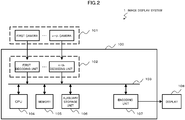
- FIG. 2 is a diagram for illustrating a hardware configuration example of the image display device 100 to which the first embodiment of the present invention is applied, and of the image display system 1 including the image display device 100.
- the image display system 1 includes the image display device 100, a camera group 101, and a display 108.
- the camera group 101 includes a plurality of cameras, from a first camera to an n-th camera (n is an integer).
- the image display system 1 is typically configured to photograph images of the vehicle surroundings by a plurality (n-number) of cameras mounted on the vehicle, combine the photographed images from each of the cameras by the image display device 100, and display an overhead view image of the surroundings of the vehicle by the display 108.
- the camera group 101 is not limited to cameras that are capable of mainly capturing visible light.
- the camera group 101 may include cameras, such as night vision cameras, that are sensitive to infrared light and are configured to output the captured infrared light as an image.
- the image display device 100 includes a decoding unit group 102 including one or a plurality of decoding units, a central processing unit (CPU) 104, a memory 105, an auxiliary storage device 106, and an encoding unit 107.
- Images transmitted from each of the cameras configuring the camera group 101 are decoded by the decoding unit group 102, which includes a decoding unit corresponding to each of the cameras in the camera group 101, and are then stored in the memory 105 via a bus 103.
- the photographed images that are from each of the cameras and stored in the memory 105 are combined by the CPU 104, and used to produce an overhead view image of the surroundings of the vehicle.
- the combined overhead view image is encoded by the encoding unit 107, and reproduced by the display 108.
- the feature quantity detection condition specifying unit 111, the feature quantity detecting unit 112, the blending ratio specifying unit 113, the overhead view image combining unit 114, and the camera control unit 130 are realized by the CPU 104. Further, the feature quantity detection condition storing unit 121 and the blend information storing unit 122 are realized by the auxiliary storage device 106 and the memory 105.
- the CPU 104 may be configured to produce images to be used to form a part of the overhead view images by using the images from each camera by performing, for example, correction processing of distortion generated by an optical system and perspective transformation processing on an image obtained by a camera having a field of view that is equal to or wider than a predetermined field of view.
- the CPU 104 is responsible for the processing for producing an overhead view image of the entire surroundings of the vehicle by performing processing such as cutting, combining, and alpha-blending of those overhead view images.
- the CPU 104 is also configured to perform processing for detecting the presence of white lines drawn on the road, obstacles, pedestrians, and the like, and for detecting the size of the surface area of those objects shown in an image by performing various types of image processing on the photographed image data, such as edge extraction, contour extraction, Gaussian processing, noise removal processing, and threshold processing.
- the encoding unit 107 is configured to encode the produced overhead view image.
- the display 108 is configured to display the overhead view image output from the image display device 100.
- the display 108 is, for example, a liquid crystal display (LCD) .
- the display 108 is not limited to this, and may be some other type of display, such as a cathode ray tube (CRT), a liquid crystal on silicon (LCOS) display, an organic light-emitting diode (OLED) display, a holographic optical element, and a projector device.
- the display 108 may be a flat monitor, a head-up display (HUD), a head-mounted display (HMD), and the like.
- FIG. 3 is a diagram for illustrating an example of a usage state of the image display device.
- this usage state an example of an image obtained by photographing the same object 205 by a plurality of cameras arranged on a vehicle 200 is illustrated.
- This example is an illustration of a state in which a front camera 201, a left-side camera 202, a rear camera 203, and a right-side camera 204 are mounted on the vehicle 200, and a pedestrian (object 205) has walked in front of the vehicle 200 diagonally to the left.
- the image photographed by the front camera 201 which is mounted on the vehicle 200 facing in the forward direction that the vehicle travels, and converted into an overhead view image, is a front image 206
- the image photographed by the left-side camera 202 and converted into an overhead view image is a left-side image 207.
- the front camera 201 and the left-side camera 202 are mounted by tilting at a predetermined angle in the vertically downward direction so as to ensure a diagonally-downward (ground direction) field of view. It is to be understood that, although not shown, the image photographed by the rear camera 203 and converted into an overhead view image is produced as a rear image, and the image photographed by the right-side camera 204 and converted into an overhead view image is produced as a right-side image.
- a leg portion of the object (pedestrian) 205 is included as a front leg image 205a in the front image 206 and as a left-side leg image 205b in the left-side image 207, respectively.
- correction processing of lens distortion occurring at an image edge portion and perspective transformation for changing the magnification ratio based on the depth distance are performed on the images photographed by the cameras.
- a three-dimensional object in the overhead view image is photographed as if the object has been stretched.
- the three-dimensional object is displayed extending in the direction of the arrow from the front camera 201 like the front leg image 205a.
- the three-dimensional object is displayed extending in the direction of the arrow from the left-side camera 202 like the left-side leg image 205b.
- the object (pedestrian) 205 which originally is the same object, is displayed as the front leg image 205a and the left-side leg image 205b extending in different directions due to differences in the viewpoint positions of the cameras in the overhead view images.
- This phenomenon occurs due to the fact that the object (pedestrian) 205 is a three-dimensional object.
- the object is not a three-dimensional object, for example, in the case of a flat pattern drawn on the road, such as a white line 208, the object is photographed without any differences in shape in the overhead view images, as shown by white lines 208a and 208b in the overhead view images. Further, the white lines 208a and 208b may be superimposed on each other by aligning their positions.
- a three-dimensional object may be considered to be present.
- a feature indicating that there is no difference in the shape of the object in the two images it may be determined that a roughly flat object is present on the road.
- the direction in which the shape of the three-dimensional object extends in an overhead view image is determined based on the positional relationship between the camera and the three-dimensional object, as shown by the direction of the arrows extending from the front camera 201 and the left-side camera 202.
- the direction in which the shape of the three-dimensional object extends in the overhead view images can be said to be an important determination condition for determining the presence of a three-dimensional object based on the detected images.
- a processing condition to be used when detecting a feature is decided based on the positional relationship between the camera, namely, the viewpoint position, and the three-dimensional object.
- FIG. 4 is a diagram for illustrating an output example of an overhead view image by the image display device 100.
- the photographed region is divided into predetermined regions, and an image of an overlapping region photographed by another camera is displayed by performing some kind of image combining.
- the surroundings of the vehicle 200 are divided into eight areas (front left area 300, front area 301, front right area 302, left area 303, right area 304, rear left area 305, rear area 306, and rear right area 307).
- the areas photographed by the front camera 201 are the front left area 300, the front area 301, and the front right area 302.
- the areas photographed by the left-side camera 202 are the front left area 300, the left area 303, and the rear left area 305.
- the other areas are also determined in the same manner based on the viewpoint position, direction, and angle of view of the rear camera 203 and the right-side camera 204.
- the front left area 300 is an area in which the images obtained by the front camera 201 and the left-side camera 202 overlap (in the following description, a region photographed in common in such a manner by a plurality of cameras is referred to as an "overlapping area").
- the front right area 302, the rear left area 305, and the rear right area 307 can also be said to be an overlapping area photographed in common by a plurality of cameras.
- the front right area 302, the rear left area 305, and the rear right area 307 are displayed as diagonal lines. However, in actual practice, the photographed object is displayed in those areas.
- the white lines 208a and 208b in the overhead view images of FIG. 3 are flat. Therefore, in the overhead view images, a white line 308 can be displayed superimposed on the same position.
- a three-dimensional object e.g., a pedestrian
- the presence of the three-dimensional object is prevented frombeing lost by performing blend processing on the front leg image 205a and the left-side leg image 205b of the pedestrian, who is the three-dimensional object, based on predetermined blending ratios, and displaying the blended images.
- the loss of a part of an image having a three-dimensional object can be avoided.
- FIG. 5 is a diagram for illustrating an outline of detection processing of a feature quantity by the image display device100.
- the feature quantity detection condition specifying unit 111 and the feature quantity detecting unit 112 perform detection processing of the feature quantity.
- a front image 400a is an image photographed by the front camera 201 and converted into an overhead view image.
- a left-side image 400b is an image photographed by the left-side camera 202 and converted into an overhead view image.
- a three-dimensional object is displayed extending in different directions due to differences in viewpoint positions, but an object on the road is displayed in an overlapping position.
- the overhead view image combining unit 114 is configured to perform processing on the other image obtained by photographing the overlapping area, which is a region in common, in order to remove objects in common from each of the images.
- a front three-dimensional object image 401a and a left-side three-dimensional object image 401b can each be obtained from which objects in common (flat objects) have been removed.
- This processing is realized by the overhead view image combining unit 114 removing from each image information on portions in common relating to a range corresponding to another image.
- the three-dimensional objects (front leg image 205a and left-side leg image 205b) shown in the front three-dimensional object image 401a and the left-side three-dimensional object image 401b, respectively, can be kept as a difference, and the objects 208a and 208b on the road can be removed as portions in common.
- the feature quantity detection condition specifying unit 111 is configured to specify a suitable detection condition. More specifically, due to the above-mentioned characteristic, the direction in which a contour of the three-dimensional object extends is based on the direction of the viewpoint position as seen from the overlapping area, and hence it can be said that a detection condition for efficiently increasing extraction accuracy is a detection condition that specifies a suitable contour scanning direction. Therefore, the feature quantity detection condition specifying unit 111 is configured to specify the feature quantity detection condition based on a geometric relationship between the viewpoint position and the region in common. Specifically, the feature quantity detection condition specifying unit 111 is configured to specify the contour scanning direction to be used in feature quantity detection based on the viewpoint position and the direction of the viewpoint position as seen from the region in common.
- contour extraction processing is performed by scanning a change amount of elements forming the image, such as brightness, the values of red, green, and blue (RGB), or the values of cyan, magenta, and yellow (CMY), in a predetermined direction (usually, the horizontal pixel direction) of the image.
- a change amount of elements forming the image such as brightness, the values of red, green, and blue (RGB), or the values of cyan, magenta, and yellow (CMY)
- a predetermined direction usually, the horizontal pixel direction
- the feature quantity detection condition specifying unit 111 is configured to set the detection condition in order to scan in an orthogonal manner to the extension direction of the contour of the three-dimensional object.
- the feature quantity detection condition specifying unit 111 is configured to specify a contour scanning direction 402a for the front three-dimensional object image 401a and a contour scanning direction 402b for the left-side three-dimensional object image 401b.
- the feature quantity detecting unit 112 is configured to detect contours 403a and 403b by scanning the front three-dimensional object image 401a based on the specified contour scanning direction 402a, and the left-side three-dimensional object image 401b based on the specified contour scanning direction 402b. An outline of the detection processing of the feature quantity has been described above.
- FIG. 6 is a diagram for showing a data structure to be stored in the feature quantity detection condition storing unit 121.
- the feature quantity detection condition storing unit 121 is configured to associate and store region specifying information 121A, a representative point 121B, viewpoint position specifying information 121C, and a feature quantity detection condition 121D.
- the region specifying information 121A is information for specifying a region to be photographed in common in a plurality of images.
- the representative point 121B is a point representing the region specified by the region specifying information 121A.
- the position specified by the representative point 121B may be, for example, a weighted center of the region, the center of the region, or any one of the apexes of the region.
- the representative point 121B is not limited to a weighted center of a photographed area, and for example, the representative point 121B may be the most distant point from the camera or the closest point to the camera in the photographed area, or a point on an object detected in the photographed area.
- the viewpoint position specifying information 121C is information for specifying the viewpoint position, namely, the position of the camera.
- the feature quantity detection condition 121D is a condition to be used in order to detect the feature quantity. For example, a condition indicating that an image rotation angle is to be applied as ⁇ ( ⁇ is a difference in the angle between the extension direction of the straight line orthogonal to a line segment from the viewpoint position to the representative point of the region and the direction for scanning the change amount of brightness in contour extraction processing) is stored in advance in the feature quantity detection condition 121D.
- FIG. 7 is a diagram for showing a data structure to be stored in the blend information storing unit 122.
- the blend information storing unit 122 is configured to associate and store region specifying information 122A and a blending ratio 122B.
- the region specifying information 122A is information for specifying a region to be photographed in common in a plurality of images.
- the blending ratio 122B is information for specifying a weighting among the images when using a plurality of images to output the combined region specified by the region specifying information 121A.
- the blending ratio 122B is information for designating that blending is to be performed by using a weighting between an image photographed by a "camera 001" and an image photographed by a “camera 002" based on the ratio of "p:(1-p)" (p is a number of from 0 to 1).
- the direction on the image when a three-dimensional object is photographed so as to extend in the front image 400a depends on the position in the area.
- the calculation processing load may be reduced by assuming this direction to be the same and setting the contour scanning direction to be the same.
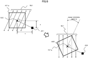
- FIG. 8 is a diagram for illustrating a relationship between a scanning direction of a feature quantity and a rotation amount of an image.
- FIG. 8 an outline of the specific method used in the processing for detecting a contour by scanning the front three-dimensional object image 401a based on a contour scanning direction 501 is illustrated.
- the front three-dimensional object image 401a includes a weighted center 500 that is shifted from the front camera (viewpoint position) 201 by x in the horizontal direction and y in the vertical direction.
- the feature quantity detection condition specifying unit 111 is configured to set the contour scanning direction 501 in a direction orthogonal to the line segment connecting the front camera (viewpoint position) 201 and the weighted center 500.
- the feature quantity detection condition specifying unit 111 is configured to rotate the front three-dimensional object image 401a by the image rotation angle ⁇ , which is shown in the feature quantity detection condition 121D, about the weighted center 500, which is the representative point of the front three-dimensional object image 401a, as the center of rotation.
- the feature quantity detection condition specifying unit 111 is not limited to this.
- the feature quantity detection condition specifying unit 111 may also be configured to rotate the processing image itself by an angle decided based on the positional relationship between the camera position and the photographed area, and then detect edges in common.
- the image rotation angle ⁇ is the difference in the angle between the extension direction of the straight line orthogonal to a line segment from the viewpoint position to the representative point of the region and the direction for scanning the change amount in brightness in the contour extraction processing.
- the direction (horizontal or vertical) for scanning the change amount in brightness and the contour scanning direction 501 can be made parallel, which allows a high accuracy to be obtained for the contour extraction.
- the rotation amount may be set to an optimum angle for each camera or for each photography direction. For example, in the case of a rear camera, when scanning in the vertical direction is suitable (e. g. , positioning when parking a vehicle in a garage etc.), the image rotation angle ⁇ may be determined so that the contour scanning direction is the vertical direction.
- FIG. 9 is a diagram for illustrating an example of a scanning direction of a feature quantity on a concentric circle, and realization means thereof.
- FIG. 9 a setting example of the extraction direction in order to enable even higher detection accuracy in the above-mentioned processing for detecting the contour is illustrated.
- FIG. 9 is an example for illustrating of a method in which, when extracting the contour from the front three-dimensional object image 401a, the scanning direction is set so as to be as close as possible to a tangential direction of a concentric circle about the front camera (viewpoint position) 201. Finely dividing and scanning one region in this manner enables the contour of a three-dimensional object to be detected by scanning in the direction roughly orthogonal to the extension direction of the contour.
- a contour scanning direction 502 is set to the tangential direction of the concentric circle from the front camera (viewpoint position) 201 for the front three-dimensional object image 401a.
- the feature quantity detection condition specifying unit 111 can specify and set scanning directions 503A to 503D of directions orthogonal to a line segment connecting the weighted center and the front camera (viewpoint position) 201 for each region, and accurately detect the contour.
- the direction in which the three-dimensional object extends is, basically, the extension direction of the line segment connecting the camera and the position of the three-dimensional object in contact with the ground.
- the contour scanning directions are different in the plane of the front three-dimensional object image 401a, there is a need to change the image display method of the contour extraction filter and the like in accordance with the search region in the image, and hence the calculation processing load increases.
- contour extraction processing can be performed by setting the contour scanning direction to be roughly orthogonal to the direction in which the three-dimensional object extends, a high extraction accuracy for the three-dimensional object can be obtained.
- the method of setting the contour scanning direction is not limited to the examples illustrated in FIG. 8 and FIG. 9 .
- a filter coefficient of an edge detection filter such as a Laplacian filter and a Sobel filter, may be decided based on the positional relationship between the viewpoint position of the front camera 201 and the overlapping area. This method enables contour extraction to be performed more accurately.
- FIG. 10 is an example of processing for, among an operation sequence of image combining in an overlapping area, deciding a blending ratio.
- an overhead view image obtained by the front camera 201 which is a "camera 1”
- an overhead view image obtained by the left-side camera 202 which is a "camera 2”
- the front left area 300 which is a region photographed in common among the regions photographed using the camera 1 and the camera 2.
- the feature quantity detection condition specifying unit 111 decides a processing condition C1 of the overhead view image obtained based on the camera 1 (Step S001). Specifically, the feature quantity detection condition specifying unit 111 refers to the feature quantity detection condition storing unit 121, and reads the feature quantity detection condition 121D that matches the combination of the region specifying information 121A corresponding to the overlapping area and the viewpoint position specifying information 121C corresponding to the mounted position of the camera 1.
- the feature quantity detection condition specifying unit 111 decides a processing condition C2 of the overhead view image obtained based on the camera 2 (Step S002). Specifically, the feature quantity detection condition specifying unit 111 refers to the feature quantity detection condition storing unit 121, and reads the feature quantity detection condition 121D that matches the combination of the region specifying information 121A corresponding to the overlapping area and the viewpoint position specifying information 121C corresponding to the mounted position of the camera 2.
- the feature quantity detecting unit 112 uses the processing condition C1 to detect a three-dimensional object present in the overlapping area of the overhead view image obtained based on the camera 1 (Step S003).
- the detected three-dimensional object has an image feature quantity Q.
- the feature quantity detecting unit 112 specifies the contour of the three-dimensional object by applying the processing condition C1 on the overhead view image obtained based on the camera 1, and scanning in the contour scanning direction under a state satisfying the processing condition C1.
- the feature quantity detecting unit 112 extracts the image feature quantity by performing, for example, contour extraction using a portion having many edges and the like, a Laplacian filter, or a Sobel filter, binarization processing, or various types of pattern recognition processing using color information, histogram information, and the like. Further, the feature quantity detecting unit 112 specifies the image feature quantity Q, which may be a position of pixels from which an edge or a contour was successfully extracted, a brightness level of the edge, and the like.
- the feature quantity detecting unit 112 uses the processing condition C2 to detect a three-dimensional object present in the overlapping area of the overhead view image obtained based on the camera 2 (Step S004).
- the detected three-dimensional object has an image feature quantity Q2.
- the feature quantity detecting unit 112 specifies the contour of the three-dimensional object by applying the processing condition C2 on the overhead view image obtained based on the camera 2, and scanning in the contour scanning direction under a state satisfying the processing condition C2.
- the feature quantity detecting unit 112 extracts the image feature quantity by performing, for example, contour extraction using a portion having many edges and the like, a Laplacian filter, or a Sobel filter, binarization processing, or various types of pattern recognition processing using color information, histogram information, and the like. Further, the feature quantity detecting unit 112 specifies the image feature quantity Q2, which may be a position of pixels from which an edge or a contour was successfully extracted, a brightness level of the edge, and the like.
- an image feature quantity obtained by a scale-invariant feature transform (SIFT), a histogram of oriented gradients (HOG), or the like may be utilized. Further, a selection may be made regarding whether feature information that was successfully extracted by combining a HOG feature quantity and a feature quantity of the shape of the pedestrian is information on a person, such as a pedestrian, or on an inanimate object. Thus, information that is more useful can be presented to a driver by switching contrast enhancement processing or the output content, such as a danger level indication, based on whether or not the object is a pedestrian or an inanimate object.
- SIFT scale-invariant feature transform
- HOG histogram of oriented gradients
- the blending ratio specifying unit 113 determines whether or not the image feature quantities Q1 and Q2 have a correlation equal to or stronger than a predetermined level (Step S005). Specifically, the blending ratio specifying unit 113 determines whether or not the pixel positions of the detected object match or are gathered in a given range, and whether or not a feature quantity difference is within a predetermined range. This processing may be performed by determining a correlation of a spatial distance relationship or a semantic distance relationship by performing hitherto-existing statistical processing or clustering processing.
- the blending ratio specifying unit 113 decides that a three-dimensional object is not present in the overlapping area, and hence the overhead view images of the overlapping area are to be combined at the predetermined blending ratios by using the overhead view image obtained based on the camera 1 and the overhead view image obtained based on the camera 2.
- the blending ratio specifying unit 113 then causes the overhead view image combining unit 114 to combine the overhead view images of the overlapping area (Step S006).
- this case when combining so that the blending ratio for any one of the overhead view images is "0", this essentially enables the overhead view image obtained based on any one of the camera 1 and the camera 2 to be selected and used.
- the image of the three-dimensional object may disappear.
- the overhead view images be blended and combined based on a predetermined "non-zero" blending ratio.
- the overhead view image combining unit 114 weights, based on the blending ratios, information (e.g., brightness information or RGB information) on pixels at positions corresponding to the overhead view image obtained based on the camera 1 and the overhead view image obtained based on the camera 2, and combines the pixel information into one overhead view image.
- information e.g., brightness information or RGB information
- the overhead view image combining unit 114 finishes the blending ratio decision processing.
- the combined overhead view image is then output by transmitting the image to the encoding unit 107 and the display 108.
- the blending ratio specifying unit 113 specifies the positions in the overlapping area in which the three-dimensional object included in the overhead view image obtained based on the camera 1 and the three-dimensional object included in the overhead view image obtained based on the camera 2 are present, and determines whether or not those three-dimensional objects are at positions that are in common by a predetermined level or more (Step S007). In other words, the blending ratio specifying unit 113 determines whether or not, in the region in common, there is a region in which the feature quantity of the image obtained from each camera overlaps by a predetermined degree or more.
- the blending ratio specifying unit 113 specifies a combining weighting ratio that is based on the image feature quantity Q2 obtained based on the camera 2.
- Combining weighting P 2 F Q 2 / F Q 1 + F Q 2
- the above-mentioned predetermined operator F may be an operator for extracting and counting, in the overlapping area, the number of pixels of an image having a feature quantity that is equal to or more than a predetermined threshold.
- the size of each of the images of the three-dimensional object in the overlapping area of the overhead view image obtained based on the camera 1 and the overhead view image obtained based on the camera 2 may be used as an element for varying the blending ratio.
- the predetermined operator F may also be an operator for calculating a sum, an average, a weighted average, a weighted center, a center value, and the like, of the image feature quantity of the pixels in the overlapping area of the overhead view image obtained based on the camera 1 and the overhead view image obtained based on the camera 2.
- the magnitude of the value of the feature quantity may also be used as an element for varying the blending ratio.
- the blending ratio may also be decided for each pixel.
- a feature quantity per se of a relevant pixel may be used as F(Q1)
- a feature quantity per se of a relevant pixel may be used as F(Q2).
- the blending ratio may also be decided by comparing F(Q1) and F(Q2) for each pixel, and setting so that the image having the larger value has a larger blending ratio.
- the gradient of the change in the blending ratio may be set to be larger. Calculating the blending ratio in this manner enables the contrast of an image that stands out more (an image in which there is a high likelihood of a three-dimensional object being present) to be enhanced, while also allowing the blending ratio to be switched gently when the "ratio of the feature quantity" changes. As a result, there is an effect that an image in which there is a comparatively high likelihood of a three-dimensional object being present can be recognized by the user more easily.
- the blending ratio of the overhead view image having the larger feature quantity may be set to 1, and the blending ratio of the other overhead view image may be set to 0.
- the blending ratio may be set to be switched in steps.
- the switch in the blending ratio becomes gentler as the number of switching steps increases.
- the operator F a case has been described in which the value of the operation result increases for images in which there is a high likelihood that a three-dimensional object is present.
- the opposite may also be performed, that is, the operator F may be an operator for which the value of the operation result decreases for images in which there is a high likelihood that a three-dimensional object is present.
- the blending ratio may be calculated for a whole overlapping area or for pixel units, and the blending ratio may be used in combining processing of the whole overlapping area or of pixel units, the occurrence of unnatural image joints, such as a boundary line, in the overlapping area can be avoided. As a result, a more natural combined image can be produced.
- the blending ratio may be decided based on another method.
- the distances from a pixel position in the front left area 300 to each of the front camera 201, which is the "camera 1", and the left-side camera 202, which is the "camera 2" are respectively represented by d1 and d2, and a fixed blending ratio is set based on the ratio between the distance d1 and the distance d2.
- the blending ratio of the image from the front camera 201 may be set larger for a pixel position that is a closer distance to the front camera 201 (i.e., d1 ⁇ d2), which is the "camera 1".
- the blending ratio for pixel positions that are too close by a predetermined amount or more be corrected so as to increase the weighting of the overhead view image photographed by the camera that is more further away.
- dth d1 minimum value ⁇ dth ⁇ d1 maximum value
- the blending ratio P1 of the overhead view image based on the closer front camera 201 may be corrected so as to be lower.
- the overhead view image combining unit 114 performs overhead view image combining including representations to be emphasized, such as highlighting the presence of a three-dimensional object, by using the blending ratios (Step S009). Specifically, the overhead view image combining unit 114 weights, based on the decided blending ratios, information (e.g., brightness information or RGB information) on the pixels at positions corresponding to the overhead view image obtained based on the camera 1 and the overhead view image obtainedbased on the camera 2, and combines the pixel information into one overhead view image. When the combined overhead view image has been produced, the overhead view image combining unit 114 finishes the blending ratio decision processing. The combined overhead view image is then output by transmitting the image to the display 108.
- information e.g., brightness information or RGB information
- FIG. 11 is a diagram for illustrating a screen example in which overhead view images are combined by blending based on the feature quantities.
- the example illustrated in FIG. 11 is an example of the processing performed when it is determined in Step S005 of the blending ratio decision processing that the feature quantities are not correlated, and determined in Step S007 that the object is at a position in common, namely, an example of the processing for combining the overhead view images by using the blending ratios decided in Step S008.
- a pedestrian leg 1103 photographed by the camera 1 is shown in an overhead view image 1101 obtained based on the camera 1
- a pedestrian leg 1104 photographed by the camera 2 is shown in an overhead view image 1102 obtained based on the camera 2. Because the same overlapping area is photographed, and the pedestrian, who is a three-dimensional object, is present in that area, the legs 1103 and 1104 of the pedestrian extend in different directions to each other.
- the pedestrian leg 1103 and the pedestrian leg 1104 each have a feature quantity in a position 1108 in common. Therefore, the blending ratio "p: (1-p) "betweentheoverhead view image 1101 obtained by the camera 1 and the overhead view image 1102 obtained by the camera 2 is calculated, and based on the calculated blending ratio, the overhead view image combining unit 114 produces a combined overhead view image 1105. As a result, a pedestrian leg 1106 photographed by the camera 1 and a pedestrian leg 1107 photographed by the camera 2 are combined in accordance with their respective blending ratios, and included in combined overhead view image 1105.
- the blending ratio specifying unit 113 decides that the image having the larger feature quantity among the image feature quantities Q1 and Q2 is to be employed for the overhead view image (Step S010).
- the overhead view image combining unit 114 performs overhead view image combining by using the employed overhead view image (Step S010). Specifically, the overhead view image combining unit 114 produces a combined overhead view image by employing, of the overhead view image obtained based on the camera 1 and the overhead view image obtained based on the camera 2, the image having the larger feature quantity in the overlapping area. When the overhead view image has been produced, the overhead view image combining unit 114 finishes the blending ratio decision processing. The combined overhead view image is then output by transmitting the image to the display 108. Note that, in order to avoid an image near a joint from disappearing due to an erroneous detection, the combined overhead view image produced may be by performing the blend processing by prioritizing the blending ratio of a camera image from which a feature can be extracted.
- FIG. 12 is a diagram for illustrating a screen example in which overhead view images are combined by selecting an image.
- the example illustrated in FIG. 12 is an example of the processing performed when it is determined in Step S005 of the blending ratio decision processing that the feature quantities are not correlated, and determined in Step S007 that the object is not at a position in common, namely, an example of the processing for combining the overhead view images by selectively adopting the overhead view image in Step S010.
- a pedestrian leg 1203 photographed by the camera 1 is shown in an overhead view image 1201 obtained based on the camera 1.
- an image photographed by the camera 2 is shown, but there is no object corresponding to a leg of the pedestrian. This is because although there are no objects in the overlapping area, a pedestrian (three-dimensional object) is present near the camera 1, and that pedestrian appears as an object in the overhead view image 1201 of the camera 1. On the other hand, because there are no objects near the overhead view image 1202 of the camera 2, nothing is shown.
- the overhead view image combining unit 114 produces a combined overhead view image 1205 by employing the overhead view image 1201 photographed by the camera 1.
- the pedestrian leg 1203 photographed by the camera 1 is included in the combined overhead view image 1205.
- a combined overhead view image including a region in common can be produced by applying a feature quantity detection condition on a plurality of pieces of image information, each of the plurality of pieces of image information partially having an image obtainedby photographing a region in common from a different viewpoint position, to detect a feature quantity of the region in common, and using the feature quantity of the region in common of each image to specify a weighting for blending an image included in the region in common.
- a flat pattern drawn on a road and a three-dimensional object can be differentiated by extracting image feature quantities of camera images photographed from different directions, and determining a correlation among the extracted image feature quantities.
- whether or not the three-dimensional object is present in the overlapping area or is present outside of the overlapping area can be determined by determining a positional overlap of the feature quantities.
- the blending ratio when overhead view images are combined may be varied in accordance with each of those states, thereby allowing a good overhead view image to be obtained.
- the image display device 100 is capable of producing an overhead view image of the entire surroundings of a vehicle by utilizing images photographed by a plurality of cameras to detect obstacles and pedestrians, and capable of, based on the detection results, producing the combined overhead view image of each camera image that the obstacles and pedestrians may easily be shown in the images.
- the image display system 1 includes a plurality of image pickup devices each configured to obtain image information partially including an image obtained by photographing a region in common from a different viewpoint position, and an image display device.
- the image display device includes a feature quantity detection condition specifying unit configured to specify a feature quantity detection condition to be used as a condition for detecting a predetermined feature quantity relating to image information, a feature quantity detecting unit configured to detect the feature quantity of a region in common by applying the feature quantity detection condition on a plurality of pieces of image information, a blending ratio specifying unit configured to specify a weighting for blending images including the region in common by using the feature quantity of the region in common of each image, and an overhead view image combining unit configured to combine the overhead view images including the region in common by using a blending ratio.
- a feature quantity detection condition specifying unit configured to specify a feature quantity detection condition to be used as a condition for detecting a predetermined feature quantity relating to image information
- a feature quantity detecting unit configured to detect the feature quantity of a region in common by applying the feature quantity detection condition on a plurality of pieces of image information
- a blending ratio specifying unit configured to specify a weighting for blending images including the region in common by
- the present invention is not limited to the embodiment described above.
- the present invention includes various modified examples.
- the embodiment described above is described in detail in order to facilitate an understanding of the present invention.
- the present invention does not need to include all of the configurations described above.
- a part of the configurations of a given embodiment may be replaced with the configurations of another embodiment.
- the configurations of another embodiment may be added to the configurations of a given embodiment.
- other configurations may be added to, deleted from, or replace a part of the configurations of each embodiment.
- the image display system 1 includes the image display device 100, the camera group 101, and the display 108.
- the camera group 101 and the display 108 may be configured so as to not be directly managed by the image display system 1.
- the present invention may be applied in a case in which an overhead view image of a region to be monitored is produced by combining images acquired and transmitted by a plurality of monitoring cameras mounted on positions that are not limited to vehicles (e.g., an exhibit in an art gallery).
- combining is performed by comparing the feature quantities of a plurality of images obtained by photographing a region in common with each other to decide a blending ratio.
- the present invention is not limited to this.
- the blending ratio may be gradually changed over time so as to avoid large changes in the blending ratio compared with the previous and subsequent time points.
- FIG. 13 is a diagram for illustrating an example of changes in the blending ratio based on changes in a three-dimensional object over time.
- FIG. 13 is an example for illustrating a combined image for a case in which a pedestrian, who is a three-dimensional object, has moved through an overlapping area.
- combined images of a pedestrian are arranged in times series for an overlapping area 1300, which is a region in which the pedestrian is photographed by both the camera 1 and the camera 2, for a case in which the pedestrian walks through the overlapping area 1300 from the left side in the right direction.
- the leg 1308 photographed by the camera 2 which is shown as having the larger leg surface area, is crisply displayed.
- Blending ratio p 1 t p 1 t ⁇ 1 + k p 1 _calc t ⁇ p 1 t ⁇ 1
- a blending ratio p1(t) of the camera 1 at a time point t can be set by adding k-times (k is a number of from 0 to 1) a difference with the blending ratio at a time point (t-1) to the blending ratio at the time point (t-1).
- the value of p1_calc (t) is the before-correction blending ratio at the time t calculated based on the feature quantity.
- a blend weighting may be specified for each predetermined period, and weighting may be performed so that a change amount between the blend weightings of a period before or a period after, or the periods before and after, a predetermined period is a predetermined value or less during the blend weighting of each of those predetermined periods.
- the blending ratio may also be decided by predicting the brightness at a future time point, and setting so that the blending ratio is a smooth continuum until the predicted brightness.
- the display processing may be performed by prioritizing an image whose blending ratio one time point before was larger. Specifically, in the example illustrated in FIG. 13 , at the time point t1, which is one time point before the time point t2, P1 has the larger blending ratio.
- processing is performed that prioritizes P1, and adds a predetermined ratio or value to the detected image feature quantity, or multiplies the detected image feature quantity by a predetermined ratio or value.
- the present invention may also be employed for a method of calculating blending ratios by using motion vectors.
- motion vector information on an optical flow is utilized in order to detect image feature quantities, and the blending ratios of the overlapping area are calculated based on the detected image feature quantities to combine the images.
- the blending ratios are calculated based on the ratio of the sum of the motion vectors by utilizing the motion vectors of a plurality of frames as the feature quantities. Specifically, a sum ⁇ Cam 1 of the motion vectors in the image from the camera 1 and a sum ⁇ Cam 2 of the motion vectors 1404 in the image from the camera 2 are calculated.
- the blending ratio P1 of the camera 1 and the blending ratio P2 of the camera 2 are calculated based on Expressions (4) and (5) from the calculated ⁇ Cam 1 and ⁇ Cam 2.
- P 1 ⁇ Cam 1 / ⁇ Cam 1 + ⁇ Cam 2
- P 2 ⁇ Cam 2 / ⁇ Cam 1 + ⁇ Cam 2
- a larger blending ratio is set for a camera image having greater movement.
- a combined image 1405 including a moving object is produced based on those blending ratios. Based on this method, images with larger movements in the overlapping area can be produced that are crisper and have better contrast.
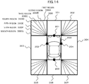
- FIG. 14 is a diagram for illustrating a setting example of a region to be photographed by the image display device 100.
- FIG. 14 can be said to be a modified example of contour detection, to which a method is applied that enables contour detection of a three-dimensional object even more accurately.
- a method is illustrated for increasing the detection accuracy of a three-dimensional object by, of the areas illustrated in FIG. 4 , dividing the overlapping areas even more finely, and reducing the deviation between the extension direction and the scanning direction.
- the front left area 300 is further divided into a fan shape, which includes a first region 300A, a second region 300B, a third region 300C, a fourth region 300D, a fifth region 300E, a sixth region 300F, and a seventh region 300G.
- the blending ratio is fixedly set for each region.
- the blending ratios for the third to sixth regions are set based on the distance from the front camera 201 and the distance from the left-side camera 202.
- the blending ratios are set by prioritizing the image from the front camera 201 as the weighted center position is closer to the front camera 201, and prioritizing the image from the left-side camera 202 as the weighted center position is closer to the left-side camera 202.
- the blending ratio may be adjusted based on the feature quantity of each camera image.
- a part or all of each of the configurations, functions, processing units, processing means, and the like described above may be realized by software for causing a processor to interpret and execute a program for realizing each of those functions.
- Information on the programs, tables, files, and the like for realizing each function may be stored in a storage device, such as a memory, a hard disk, and a solid-state drive (SSD), or a storage medium, such as an integrated chip (IC) card, a secure digital (SD) card, and a digital versatile disc (DVD).
- a storage device such as a memory, a hard disk, and a solid-state drive (SSD), or a storage medium, such as an integrated chip (IC) card, a secure digital (SD) card, and a digital versatile disc (DVD).
- IC integrated chip
- SD secure digital
- DVD digital versatile disc
- control lines and information lines considered to be necessary for the description are illustrated. It is not necessarily the case that all the control lines and information lines necessary for a product are illustrated. In actual practice, almost all the configurations may be considered as being connected to each other.
- each of the above-mentioned configurations, functions, processing units, and the like may be realized by hardware by, for example, designing those as an integrated circuit.
- the technical elements of the above-mentioned embodiments may be applied independently, or may be applied by dividing those elements into a plurality of parts, such as a program portion and a hardware portion.
Landscapes
- Engineering & Computer Science (AREA)
- Multimedia (AREA)
- Signal Processing (AREA)
- Physics & Mathematics (AREA)
- General Physics & Mathematics (AREA)
- Theoretical Computer Science (AREA)
- Mechanical Engineering (AREA)
- Image Processing (AREA)
- Closed-Circuit Television Systems (AREA)
- Image Analysis (AREA)
Applications Claiming Priority (2)
| Application Number | Priority Date | Filing Date | Title |
|---|---|---|---|
| JP2014066268A JP6371553B2 (ja) | 2014-03-27 | 2014-03-27 | 映像表示装置および映像表示システム |
| PCT/JP2015/050892 WO2015146230A1 (fr) | 2014-03-27 | 2015-01-15 | Dispositif et système d'affichage d'image |
Publications (2)
| Publication Number | Publication Date |
|---|---|
| EP3125544A1 true EP3125544A1 (fr) | 2017-02-01 |
| EP3125544A4 EP3125544A4 (fr) | 2017-09-20 |
Family
ID=54194772
Family Applications (1)
| Application Number | Title | Priority Date | Filing Date |
|---|---|---|---|
| EP15769792.1A Withdrawn EP3125544A4 (fr) | 2014-03-27 | 2015-01-15 | Dispositif et système d'affichage d'image |
Country Status (5)
| Country | Link |
|---|---|
| US (1) | US20170006234A1 (fr) |
| EP (1) | EP3125544A4 (fr) |
| JP (1) | JP6371553B2 (fr) |
| CN (1) | CN105960800A (fr) |
| WO (1) | WO2015146230A1 (fr) |
Families Citing this family (24)
| Publication number | Priority date | Publication date | Assignee | Title |
|---|---|---|---|---|
| US20160217333A1 (en) * | 2015-01-26 | 2016-07-28 | Ricoh Company, Ltd. | Information processing apparatus and information processing system |
| US20170270378A1 (en) * | 2016-03-16 | 2017-09-21 | Haike Guan | Recognition device, recognition method of object, and computer-readable recording medium |
| JP6669569B2 (ja) * | 2016-04-04 | 2020-03-18 | アルパイン株式会社 | 車両用周辺監視装置 |
| WO2017191978A1 (fr) * | 2016-05-02 | 2017-11-09 | Samsung Electronics Co., Ltd. | Procédé, appareil et support d'enregistrement pour traiter une image |
| JP6586051B2 (ja) * | 2016-06-30 | 2019-10-02 | 株式会社 日立産業制御ソリューションズ | 画像処理装置および画像処理方法 |
| CN107666590B (zh) * | 2016-07-29 | 2020-01-17 | 华为终端有限公司 | 一种目标监控方法、摄像头、控制器和目标监控系统 |
| DE102016225073A1 (de) | 2016-12-15 | 2018-06-21 | Conti Temic Microelectronic Gmbh | Vorrichtung zur bereitstellung einer verbesserten hinderniserkennung |
| US11176675B2 (en) | 2017-02-01 | 2021-11-16 | Conflu3Nce Ltd | System and method for creating an image and/or automatically interpreting images |
| US11158060B2 (en) * | 2017-02-01 | 2021-10-26 | Conflu3Nce Ltd | System and method for creating an image and/or automatically interpreting images |
| WO2018146997A1 (fr) * | 2017-02-07 | 2018-08-16 | 日本電気株式会社 | Dispositif de détection d'objet tridimensionnel |
| JP6861599B2 (ja) * | 2017-08-31 | 2021-04-21 | フォルシアクラリオン・エレクトロニクス株式会社 | 周辺監視装置 |
| JP2019185381A (ja) * | 2018-04-10 | 2019-10-24 | クラリオン株式会社 | 車両周囲画像生成装置 |
| US11846514B1 (en) * | 2018-05-03 | 2023-12-19 | Zoox, Inc. | User interface and augmented reality for representing vehicles and persons |
| US10809081B1 (en) | 2018-05-03 | 2020-10-20 | Zoox, Inc. | User interface and augmented reality for identifying vehicles and persons |
| US10837788B1 (en) | 2018-05-03 | 2020-11-17 | Zoox, Inc. | Techniques for identifying vehicles and persons |
| JP2021144257A (ja) | 2018-06-06 | 2021-09-24 | ソニーグループ株式会社 | 情報処理装置、情報処理方法、プログラム、及び、移動体 |
| GB2582262B (en) * | 2019-03-02 | 2022-09-28 | Jaguar Land Rover Ltd | Imaging system and method |
| US11216920B2 (en) * | 2019-05-31 | 2022-01-04 | Apple Inc. | Enhanced local contrast |
| JP7314680B2 (ja) * | 2019-07-23 | 2023-07-26 | 東洋製罐株式会社 | 画像データ処理システム、無人航空機、画像データ処理方法、及びプログラム |
| KR20210030523A (ko) * | 2019-09-09 | 2021-03-18 | 현대자동차주식회사 | 차량 및 그 제어 방법 |
| JP7367776B2 (ja) * | 2019-12-27 | 2023-10-24 | 株式会社ソシオネクスト | 画像処理装置、画像処理方法、および画像処理プログラム |
| CN113496601B (zh) * | 2020-03-20 | 2022-05-24 | 宇通客车股份有限公司 | 一种车辆辅助驾驶方法、装置和系统 |
| WO2021192096A1 (fr) * | 2020-03-25 | 2021-09-30 | 三菱電機株式会社 | Dispositif de traitement d'images, procédé de traitement d'images, et programme de traitement d'images |
| DE102020109997A1 (de) | 2020-04-09 | 2021-10-14 | Connaught Electronics Ltd. | System und Verfahren, um zuverlässige gestitchte Bilder zu machen |
Family Cites Families (11)
| Publication number | Priority date | Publication date | Assignee | Title |
|---|---|---|---|---|
| US8136354B2 (en) * | 2008-03-14 | 2012-03-20 | Energy Compression Inc. | Adsorption-enhanced compressed air energy storage |
| EP2285109B1 (fr) * | 2008-05-29 | 2018-11-28 | Fujitsu Limited | Processeur d'image de véhicule et système de traitement d'image de véhicule |
| JP4876118B2 (ja) * | 2008-12-08 | 2012-02-15 | 日立オートモティブシステムズ株式会社 | 立体物出現検知装置 |
| JP5212651B2 (ja) * | 2009-03-27 | 2013-06-19 | 株式会社デンソー | 車外撮影画像表示システム。 |
| JP2010250640A (ja) * | 2009-04-17 | 2010-11-04 | Sanyo Electric Co Ltd | 画像処理装置 |
| JP5548002B2 (ja) * | 2010-03-25 | 2014-07-16 | 富士通テン株式会社 | 画像生成装置、画像表示システム及び画像生成方法 |
| JP5483120B2 (ja) * | 2011-07-26 | 2014-05-07 | アイシン精機株式会社 | 車両周辺監視システム |
| JP5682788B2 (ja) * | 2011-09-27 | 2015-03-11 | アイシン精機株式会社 | 車両周辺監視装置 |
| KR101371458B1 (ko) * | 2012-07-16 | 2014-03-10 | 현대자동차주식회사 | 오픈카의 배플구조 |
| JP6084434B2 (ja) * | 2012-10-31 | 2017-02-22 | クラリオン株式会社 | 画像処理システム及び画像処理方法 |
| JP6224251B2 (ja) * | 2013-12-19 | 2017-11-01 | インテル コーポレイション | ボウル形状イメージングシステム |
-
2014
- 2014-03-27 JP JP2014066268A patent/JP6371553B2/ja active Active
-
2015
- 2015-01-15 US US15/125,719 patent/US20170006234A1/en not_active Abandoned
- 2015-01-15 WO PCT/JP2015/050892 patent/WO2015146230A1/fr active Application Filing
- 2015-01-15 CN CN201580006815.3A patent/CN105960800A/zh active Pending
- 2015-01-15 EP EP15769792.1A patent/EP3125544A4/fr not_active Withdrawn
Also Published As
| Publication number | Publication date |
|---|---|
| WO2015146230A1 (fr) | 2015-10-01 |
| JP2015192198A (ja) | 2015-11-02 |
| EP3125544A4 (fr) | 2017-09-20 |
| US20170006234A1 (en) | 2017-01-05 |
| CN105960800A (zh) | 2016-09-21 |
| JP6371553B2 (ja) | 2018-08-08 |
Similar Documents
| Publication | Publication Date | Title |
|---|---|---|
| EP3125544A1 (fr) | Dispositif et système d'affichage d'image | |
| JP6084434B2 (ja) | 画像処理システム及び画像処理方法 | |
| US10304164B2 (en) | Image processing apparatus, image processing method, and storage medium for performing lighting processing for image data | |
| US11087169B2 (en) | Image processing apparatus that identifies object and method therefor | |
| US20200293809A1 (en) | Image processing apparatus, image processing method, and storage medium | |
| US9253388B2 (en) | Image processing device and method, and program | |
| KR102464523B1 (ko) | 이미지 속성 맵을 프로세싱하기 위한 방법 및 장치 | |
| US8055016B2 (en) | Apparatus and method for normalizing face image used for detecting drowsy driving | |
| US10650526B2 (en) | Image processing apparatus, image capturing apparatus, image processing method, and storage medium | |
| KR20200023651A (ko) | 미리보기 사진 블러링 방법 및 장치 및 저장 매체 | |
| US9619886B2 (en) | Image processing apparatus, imaging apparatus, image processing method and program | |
| WO2013156101A9 (fr) | Procédé et système optique pour déterminer une carte de profondeur d'une image | |
| JP7159384B2 (ja) | 画像処理装置、画像処理方法、及びプログラム | |
| WO2015008717A1 (fr) | Dispositif de traitement d'image et appareil d'imagerie | |
| US20200218343A1 (en) | Gaze point compensation method and apparatus in display device, and display device | |
| CN110166680B (zh) | 设备成像方法、装置、存储介质及电子设备 | |
| US20160180514A1 (en) | Image processing method and electronic device thereof | |
| KR102262671B1 (ko) | 비디오 영상에 보케 효과를 적용하는 방법 및 기록매체 | |
| JP6986854B2 (ja) | 画像処理装置、撮像装置、画像処理方法、及びプログラム | |
| CN111563517A (zh) | 图像处理方法、装置、电子设备及存储介质 | |
| JP2016219879A (ja) | 画像処理装置、画像処理方法及びプログラム | |
| KR101592087B1 (ko) | 배경 영상의 위치를 이용한 관심맵 생성 방법 및 이를 기록한 기록 매체 | |
| JP6579764B2 (ja) | 画像処理装置、画像処理方法およびプログラム | |
| JP6351364B2 (ja) | 情報処理装置、情報処理方法およびプログラム | |
| JP5891751B2 (ja) | 画像間差分装置および画像間差分方法 |
Legal Events
| Date | Code | Title | Description |
|---|---|---|---|
| PUAI | Public reference made under article 153(3) epc to a published international application that has entered the european phase |
Free format text: ORIGINAL CODE: 0009012 |
|
| 17P | Request for examination filed |
Effective date: 20160913 |
|
| AK | Designated contracting states |
Kind code of ref document: A1 Designated state(s): AL AT BE BG CH CY CZ DE DK EE ES FI FR GB GR HR HU IE IS IT LI LT LU LV MC MK MT NL NO PL PT RO RS SE SI SK SM TR |
|
| AX | Request for extension of the european patent |
Extension state: BA ME |
|
| DAX | Request for extension of the european patent (deleted) | ||
| A4 | Supplementary search report drawn up and despatched |
Effective date: 20170823 |
|
| RIC1 | Information provided on ipc code assigned before grant |
Ipc: B60R 1/00 20060101ALI20170817BHEP Ipc: G06T 3/40 20060101ALI20170817BHEP Ipc: H04N 7/18 20060101AFI20170817BHEP Ipc: G06T 1/00 20060101ALI20170817BHEP |
|
| 17Q | First examination report despatched |
Effective date: 20191014 |
|
| STAA | Information on the status of an ep patent application or granted ep patent |
Free format text: STATUS: THE APPLICATION HAS BEEN WITHDRAWN |
|
| 18W | Application withdrawn |
Effective date: 20191108 |