EP3125262A1 - Hybrid switching device - Google Patents
Hybrid switching device Download PDFInfo
- Publication number
- EP3125262A1 EP3125262A1 EP14887580.0A EP14887580A EP3125262A1 EP 3125262 A1 EP3125262 A1 EP 3125262A1 EP 14887580 A EP14887580 A EP 14887580A EP 3125262 A1 EP3125262 A1 EP 3125262A1
- Authority
- EP
- European Patent Office
- Prior art keywords
- support
- insulator
- coil
- switch
- actuation unit
- Prior art date
- Legal status (The legal status is an assumption and is not a legal conclusion. Google has not performed a legal analysis and makes no representation as to the accuracy of the status listed.)
- Granted
Links
Images



Classifications
-
- H—ELECTRICITY
- H01—ELECTRIC ELEMENTS
- H01H—ELECTRIC SWITCHES; RELAYS; SELECTORS; EMERGENCY PROTECTIVE DEVICES
- H01H33/00—High-tension or heavy-current switches with arc-extinguishing or arc-preventing means
- H01H33/60—Switches wherein the means for extinguishing or preventing the arc do not include separate means for obtaining or increasing flow of arc-extinguishing fluid
- H01H33/66—Vacuum switches
- H01H33/666—Operating arrangements
- H01H33/6661—Combination with other type of switch, e.g. for load break switches
-
- H—ELECTRICITY
- H01—ELECTRIC ELEMENTS
- H01H—ELECTRIC SWITCHES; RELAYS; SELECTORS; EMERGENCY PROTECTIVE DEVICES
- H01H33/00—High-tension or heavy-current switches with arc-extinguishing or arc-preventing means
- H01H33/02—Details
- H01H33/04—Means for extinguishing or preventing arc between current-carrying parts
- H01H33/14—Multiple main contacts for the purpose of dividing the current through, or potential drop along, the arc
- H01H33/143—Multiple main contacts for the purpose of dividing the current through, or potential drop along, the arc of different construction or type
-
- H—ELECTRICITY
- H01—ELECTRIC ELEMENTS
- H01H—ELECTRIC SWITCHES; RELAYS; SELECTORS; EMERGENCY PROTECTIVE DEVICES
- H01H33/00—High-tension or heavy-current switches with arc-extinguishing or arc-preventing means
- H01H33/02—Details
- H01H33/42—Driving mechanisms
Definitions
- Embodiments of the present disclosure relate to a multi-point breaking complex type switch that connects and disconnects a plurality of contacts.
- High-voltage switches breaking a fault current are required to certainly break various currents from a small current to a large current.
- the large current in particular, the following two current breaking performance must be achieved.
- the switches must have a performance capable of coping with an applied voltage which has a gradual initial rising of the transient recovery voltage but with an absolute value becoming high at the time of termination.
- switches achieving the above two current breaking performance by connecting circuit breakers respectively dedicated to each circuit breaking performance are also in development. That is, this type of switches has a plurality of circuit breakers with each circuit breaker bearing an individual current breaking performance. This type of switches has an internal space of the single pressure container divided into two spaces, and the circuit breaker placed in each divided space.
- a puffer-type circuit breaker with an excellent BTF breaking performance is placed in one of the divided internal space, and a puffer-type circuit breaker with an excellent SLF breaking performance is placed in the other divided internal space.
- both circuit breakers are electrically connected in series.
- Patent Document 1 JP 2003-348721 A
- each circuit breaker has a contact that can be connected and disconnected.
- an actuator which is a single actuation unit performs the current breaking action and the input action for all contacts, the load of the actuation unit will be heavy. This restricts the type and size of the actuation unit, and when it is difficult to increase the operation energy, the current breaking time becomes long.
- Embodiments of the present disclosure have been proposed in order to address the foregoing technical problems of conventional technologies, and the objective is to provide a complex type switch which is capable of easily achieve a plurality of current breaking performance required for a high-voltage switch, and has a short current breaking time.
- a complex type switch according to an embodiment of the present disclosure is proposed to achieve the above objective, and includes the following features:
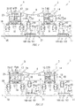
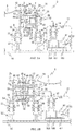
- FIGs. 1, 2 are cross-sectional views illustrating an entire structure of the complex type switch in this embodiment.
- FIG. 1 illustrates an input status
- FIG. 2 illustrates a current breaking status.
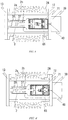
- FIG. 3 is a partially enlarged cross-sectional views of FIG. 1
- FIG. 4 is a partially enlarged cross-sectional view of FIG. 2 .
- a complex type switch 1 in the present embodiment includes a vacuum switch 3 and a high-voltage resistant switch 5.
- the vacuum switch 3 is a switch that includes a vacuum valve 2 as a contact.
- the high-voltage resistant switch 5 is a switch that includes a contact 4 which has a larger dielectric strength than that of the vacuum switch 3.
- the vacuum switch 3 and the high-voltage resistant switch 5 are arranged side by side in the horizontal direction on a base 16 that is an installation surface, and are electrically connected in series via an insulated wiring 6.
- the vacuum switch 3 includes a pressure container 7, a support 8, a contact part 9, an actuation unit 10, and a power supply 11.
- the pressure container 7 is a cylindrical sealed container formed of an insulator and a metal. The openings at both ends of the insulator that is a barrel part of the pressure container 7 are sealed by metal lids 12, 13, respectively. An electrical insulation is achieved between the metal lids 12, 13. Current-carrying plates 14, 15 are installed at respective ends of the metal lids 12, 13.
- the vacuum switch 3 is connected to an unillustrated bus line via the current-carrying plate 14, and is connected to the high-voltage resistant switch 5 from the current-carrying plate 15 via the insulated wiring 6.
- the insulated wiring 6 is a wiring that has an ensured insulation from the exterior by, for example, insulative cover.
- the support 8 supports the pressure container 7, and ensures the insulation relative to the ground.
- the support 8 is installed between the base 16 that fastens the vacuum switch 3, and the pressure container 7 in a high-voltage status.
- the support 8 mechanically supports the pressure container 7, and ensures the insulation distance between the base 16 and the pressure container 7. That is, the support 8 ensures the electrical insulation between the pressure container 7 and the ground surface.
- the contact part 9 includes the vacuum valve 2 and a shield 65.
- the contact part 9 is placed in the pressure container 7, and is connected to the metal lids 12, 13 of the pressure container 7 directly or via the actuation unit 10.
- the actuation unit 10 is a mechanism that actuates the vacuum valve 2 of the contact part 9.
- the actuation unit 10 is connected to the end of the pressure container 7, and applies kinetic energy to the vacuum valve 2 of the contact part 9, thereby actuating the vacuum valve 2 to connect, disconnect, close and open. This changes the conduction status of the vacuum switch 3.
- the power supply 11 is installed on the base 16, and is a power supply source to actuate the actuation unit 10.
- the high-voltage resistant switch 5 includes a pressure container 17, a support 18, a contact part 19, an operation part 20, and a power supply 21.
- the pressure container 17 is a cylindrical sealed container formed of an insulator and a metal. The openings at both ends of the insulator that is a barrel part of the pressure container 17 are sealed by metal lids 22, 23, respectively. An electrical insulation is achieved between the metal lids 22, 23. Current-carrying plates 24, 25 are installed at respective ends of the metal lids 22, 23.
- the high-voltage resistant switch 5 is connected to the vacuum switch 3 from the current-carrying plate 24 via the insulated wiring 6, and is connected to the unillustrated bus line via the current-carrying plate 25.
- the support 18 supports the pressure container 17, and ensures the insulation relative to the ground.
- the support 18 is installed between the base 16 that fix the high-voltage resistant switch 5, and the pressure container 17 in a high-voltage status.
- the support 18 mechanically supports the pressure container 17, and ensures the insulation distance between the base 16 and the pressure container 17. That is, the support 18 ensures the electrical insulation between the pressure container 17 and the ground surface.
- the contact part 19 includes a contact 4 and shields 66, 67.
- the contact part 19 is placed in the pressure container 17, and is connected to the metal lids 22, 23 of the pressure container 17 directly or via the actuation unit 20.
- the actuation unit 20 is a mechanism that actuates the contact 4 of the contact part 19.
- the actuation unit 20 is connected to the end of the pressure container 17, applies kinetic energy to the contact 4 of the contactor 19, thereby actuating the contact 4 to connect, disconnect, close and open. This changes the conduction status of the high-voltage resistant switch 5.
- the power supply 21 is installed on the base 16, and is a power supply source to actuate the actuation unit 20.
- FIGs. 3A , 4A are enlarged cross-sectional views of the vacuum switch 3.
- FIG. 3A illustrates the input status
- FIG. 4A illustrates the current breaking status.
- the pressure container 7 includes an insulator tank 26 and the metal lids 12, 13.
- the insulator tank 26 has an insulator tube 27 having both ends opened as a barrel part, and metal flanges 28, 29 are adhered to the respective open ends.
- the metal flanges 28, 29 are fixed with the metal lids 12, 13, respectively.
- An internal space 68 of the pressure container 7 is in a sealed condition.
- This internal space 68 is filled with an insulative medium.
- An exemplary insulative medium is a sulfur hexafluoride gas (SF6 gas), carbon dioxide, nitrogen, dry air, a mixture gas thereof, or an insulative oil. In the embodiment, the SF6 gas is applied.
- the support 8 includes support insulators 30, 31, support structures 32, 33, and metal fittings 34, 35.
- the support structures 32, 33 are metal pedestal that stands upright, and have lower ends fixed to the base 16.
- the support insulators 30, 31 are support beams that have both metal ends insulated by insulator.
- the lower ends of the support insulators 30, 31 are fixed to the upper ends of the support structures 32, 33.
- the upper ends of the support insulators 30, 31 are connected to the metal lids 12, 13 via the metal fittings 34, 35.
- the support 8 supports the pressure container 7 structurally stable.
- the lengths of the support insulators 30, 31 are designed to be longer than the insulation distance between the pressure container 7 and the ground (support structure).[0029] (3) Contact part
- the contact part 9 includes the vacuum valve 2 and the shield 65.
- the vacuum valve 2 includes a fixed electrode 36, a movable electrode 37, a vacuum container 2a, and a bellows 2b.
- the fixed electrode 36 is directly fixed to the metal lid 13.
- the movable electrode 37 is connected to the metal lid 12 via a drive device 38 of the actuation unit 10.
- the vacuum container 2a is a container which contains therein the fixed electrode 36 and the movable electrode 37, and is formed of an insulator sealed in a vacuum condition.
- the bellows 2b is a flexible stretchable member that attaches the movable electrode 37 to the vacuum container 2a to be movable while maintaining airtight condition.
- the gas pressure of the internal space 68 is equal to or lower than the gas pressure of an internal space 69 explained later and equal to or higher than the atmospheric pressure. This is the pressure that the bellows 2b can withstand.
- the shield 65 is disposed so as to ease the concentration of the electric field around the vacuum valve 2, and is connected to the metal lid 12.
- the actuation unit 10 includes the drive device 38, and a control device 39.
- the drive device 38 is fixed to the metal lid 12 inside the pressure container 7.
- the drive shaft of the drive device 38 is connected to the movable electrode 37, and drives the vacuum valve 2 so as to be freely connected and disconnected.
- the connection between the drive device 38 and the movable electrode 37 not an insulation material but a conductive material is applied. This achieves an equipotential.
- the conductive material a metal material with high conductivity is preferably used.
- the control device 39 is fixed to the metal lid 12 outside the pressure container 7, and is connected to the drive device 38 via an insulated wiring 40 that passes through the metal lid 12. Hence, the control device 39 adjusts the power supplied to the drive device 38, thereby controlling the action of the drive device 38.
- the actuation unit 10 pushes and pulls the movable electrode 37 linearly, so as to connect, disconnect, open and close the fixed electrode 36, by applying drive force to the mechanically connected movable electrode 37.
- the action of the actuation unit 10 may be started by, for example, when the control device 39 receives an instruction signal from an unillustrated signal output device installed outside the vacuum switch 3.
- a sealer that includes an unillustrated elastic material is provided at the metal lid 12 of the pressure container 7 in which the insulated wiring 40 passes through, and thus the gas-tightness of the internal space 68 is maintained.
- the power supply 11 includes a transformer 41, the bus line 42, a pressure container 161, and an insulator tube 162.
- the container of the transformer 41 and the pressure container 161 are fixed to the base 16 via the support structure 163.
- the opening of the container of the transformer 41 is fixed to the one opening of the pressure container 161.
- the other opening of the pressure container 161 is fixed to the opening of the insulator tube 162.
- the transformer 41, the pressure container 161, and the insulator tube 162 share an internal space 164 that is sealed and filled with an insulative medium.
- the filled insulative medium is the same as the one explained above.
- the primary side of the transformer 41 is connected to the bus line 42 via an insulated wiring 43.
- the secondary side of the transformer 41 is connected to an insulated wiring 44.
- the insulated wiring 44 passes through the internal space 164, passes through the end of the insulator tube 162 at the actuation unit10 side, and is connected to the control device 39 of the actuation unit 10.
- Sealers including unillustrated elastic materials are provided to the transformer 41 and the insulator tube 162 in which the insulated wirings 43, 44 pass through, and thus the gas-tightness of the internal space 164 is maintained.
- the dielectric strength between the primary and secondary sides of the transformer 41 and the dielectric strength between both ends of the insulator tube 162 are designed to be larger than the required dielectric strength between the pressure container 7 and the ground.
- the bus line 42 is connected to an unillustrated power supply source.
- the power supplied from the power supply source via the bus line 42 is boosted by the transformer 41 up to the necessary voltage to drive the actuation unit 10, and the boosted voltage is supplied thereto. That is, the power supply 11 supplies the power to the actuation unit 10 that has a voltage to ground in a high-voltage status without any short-circuit to the ground.
- FIGs. 3B , 4B are enlarged cross-sectional views illustrating the high-voltage resistant switch 5, and FIG. 3B illustrates an input status, and FIG. 4B illustrates a current breaking status.
- the pressure container 17 includes an insulator tank 45 and the metal lids 22, 23.
- the insulator tank 45 has an insulator tube 46 having both ends opened as a barrel part, and metal flanges 47, 48 are adhered to the respective open ends.
- the metal flanges 47, 48 are fixed to the metal lids 22, 23, respectively.
- the internal space 69 of the pressure container 17 is in a sealed condition, and is filled with the insulative medium.
- the insulative medium to be filled is same as the one as explained above.
- the support 18 includes support insulators 49, 50, support structures 51, 52, and metal fittings 53, 54.
- the support structures 51, 52 are metal pedestal that stands upright, and have the lower ends fixed to the base 16.
- the support insulators 49, 50 are support beams that have both metal ends insulated by insulator.
- the lower ends of the support insulators 49, 50 are fixed to the upper ends of the support structures 51, 52.
- the upper ends of the support insulators 49, 50 are connected to the metal lids 22, 23 via the metal fittings 53, 54.
- the support 18 supports the pressure container 17 structurally stable.
- the lengths of the support insulators 49, 50 are designed to be longer than the insulation distance between the pressure container 17 and the ground (support structure). This ensures the electrical insulation of the pressure container 17 to the ground surface.
- the contact part 19 includes the contact 4, and the shields 66, 67.
- the contact 4 includes a fixed electrode 55 and a movable electrode 56.
- the stationary electrode 55 is directly fixed to the metal lid 23.
- the movable electrode 56 is connected to the metal lid 22 via a drive device 57 of the actuation unit 20.
- the shields 66, 67 are disposed so as to ease the concentration of the electric field around the contact 4, and are connected to the metal lids 22, 23, respectively.
- the actuation unit 20 includes the drive device 57, and a control device 58.
- the drive device 57 is fixed to the metal lid 22 inside the pressure container 17.
- the drive shaft of the drive device 57 is connected to the movable electrode 56, and drives the contact 4 to be freely connected and disconnected.
- the connection between the drive device 57 and the movable electrode 56 not an insulation material but a conductive material is applied. This achieves an equipotential.
- the conductive material a metal material with high conductivity is preferably used.
- the control device 58 is fixed to the metal lid 22 outside the pressure container 17, and is connected to the drive device 57 via an insulated wiring 59 that passes through the metal lid 22. Hence, the control device 58 adjusts the power supplied to the drive device 57, thereby controlling the action of the drive device 57.
- the actuation unit 20 pushes and pulls the movable electrode 56 linearly, so as to connect, disconnect, open and close the fixed electrode 55, by applying drive force to the mechanically connected movable electrode 56.
- the action of the actuation unit 20 may be started by, for example, when the control device 58 receives an instruction signal from an unillustrated signal output device installed outside the high-voltage resistant switch 5.
- a sealer that includes an unillustrated elastic material provided at the metal lid 22 of the pressure container 17 in which the insulated wiring 59 passes through, and thus the gas-tightness of the internal space 69 is maintained.
- the power supply 21 includes a transformer 60, the bus line 61, a pressure container 165, and an insulator tube 166.
- the container of the transformer 60 and the pressure container 165 are fixed to the base 16 via the support structure 167.
- the opening of the container of the transformer 60 is fixed to the one opening of the pressure container 165.
- the other opening of the pressure container 165 is fixed to the opening of the insulator tube 166.
- the transformer 60, the pressure container 165, and the insulator tube 166 share an internal space 168 that is sealed and filled with an insulative medium.
- the filled insulative medium is the same as the one explained above.
- the primary side of the transformer 60 is connected to the bus line 61 via an insulated wiring 62.
- the secondary side of the transformer 60 is connected to an insulated wiring 63.
- the insulated wiring 63 passes through the internal space 168, passes through the end of the insulator tube 166 at the actuation unit-20 side, and is connected to the control device 58 of the actuation unit 20.
- Sealers including unillustrated elastic materials are provided to the transformer 60 and the insulator tube 166 in which the insulated wirings 62, 63 pass through, and thus the gas-tightness of the internal space 168 is maintained.
- the dielectric strength between the primary and secondary sides of the transformer 60 and the dielectric strength between both ends of the insulator tube 166 are designed to be larger than the required dielectric strength between the pressure container 17 and the ground.
- the bus line 61 is connected to an unillustrated power supply source.
- the power supplied from the power supply source via the bus line 61 is boosted by the transformer 60 up to the necessary voltage to drive the actuation unit 20, and the boosted voltage is supplied thereto. That is, the power supply 21 supplies the power to the actuation unit 20 that has a voltage to ground in a high-voltage status without any short-circuit to the ground.
- FIGs. 1 , 3A, 3B illustrate the input status
- FIGs. 2 , 4A, 4B illustrate the current breaking status
- the current derived from the current-carrying plate 14 flows through the metal lid 12, the drive device 38, the movable electrode 37, the fixed electrode 36, the metal lid 13, and the current-carrying plate 15.
- the current flows from the current-carrying plate 15 to, via the insulated wiring 6, the current-carrying plate 24, the metal lid 22, the drive device 57, the movable electrode 56, the fixed electrode 55, and the metal lid 23 in sequence, and is derived to the current-carrying plate 25.
- the movable electrode 37 of the vacuum valve 2 are opened and disconnected from the fixed electrode 38. During this action, an arc including evaporated particles from the electrode and electrons is produced between the movable electrode 37 and the fixed electrode 38.
- the substances forming the arc are diffused, and are unable to maintain its form, thus being dissipated. Hence, the flowing current is broken.
- the movable electrode 56 of the contact 4 is opened and disconnected from the fixed electrode 55, and an arc is produced between those electrodes, but the arc will be extinguished by ensuring the insulation distance between those electrodes.
- the separation gas of the SF6 gas produced by the arc is produced in the internal space 69 of the high-voltage resistant switch 5.
- This separation gas has an action of corroding the surface layer of the vacuum container 2a of the vacuum valve 2 formed of the insulator.
- the corrosion thereof by the separation gas produced in the internal space 69 is preventable.
- the bellows 2b of the vacuum valve 2 may have a pressure resistance not so high.
- the gas pressure in the internal space 68 is set to be equal to or lower than the gas pressure in the internal space 69 and equal to or higher than the atmospheric pressure which is a pressure the bellows 2b can resist. Accordingly, the bellows 2b of the internal space 68 is protected while the dielectric strength at the contact 4 in the internal space 69 is ensured.
- the vacuum switch 3 bears the keen transient recovery voltage in the SLF breaking performance, and the high-voltage resistant switch 5 that has a high dielectric strength bears a high transient recovery voltage in the BTF breaking performance. Hence, both breaking performances are easily achieved.
- FIGs. 5, 6 are enlarged cross-sectional views of the vacuum switch 3 according to the second embodiment, and FIG. 5 illustrates the input status of the vacuum switch 3, and FIG. 6 illustrates the current breaking status of the vacuum switch 3.
- FIGs. 7, 8 are enlarged cross-sectional views of an electromagnetic repulsion drive device 71 in FIGs. 5, 6 , respectively.
- the basic structure is same as that of the first embodiment. Hence, only the differences between the first embodiment will be explained, and the same part as that of the first embodiment will be denoted by the same reference numeral, and the detailed explanation will be omitted.
- the electromagnetic repulsion drive device 71 utilizes electromagnetic repulsion force for the drive force of the electrode opening action, and has a high responsiveness in the electrode opening action.
- This electromagnetic repulsion drive device 71 includes a mechanism box 72, a fast-speed electrode opening unit 73, a wiping mechanism unit 74, and a holding mechanism unit 75. Each component will be explained in detail below.
- the mechanism box 72 is a box with a hollow interior which has one end opened at the vacuum-valve-2 side.
- a support 80 that is a wall surface separating the mechanism box 72 from the exterior is fixed to the opening of the mechanism box 72.
- a hole 80a that slidably supports the movable electrode 37 of the vacuum valve 2 is formed in the center of the support 80.
- the bottom of the mechanism box 72 opposite to the support-80 side is fixed and connected to the wall surface of the metal lid 12 inside the pressure container 7.
- the fast-speed electrode opening unit 73, the wiping mechanism unit 74, and the holding mechanism 75 are placed in such mechanism box 72.
- the fast-speed electrode opening unit 73 includes a movable shaft 76, an electromagnetic repulsion coil 77, a repulsion ring 78, and a repulsion ring catcher 79.
- the movable shaft 76 is a bar member coaxially connected to the movable electrode 37 of the vacuum valve 2.
- the repulsion ring catcher 79 is an annular member that is fitted in the movable shaft 76 and is integrated therewith.
- the repulsion ring 78 is an annular body formed of a good conductor.
- the repulsion ring 78 is coaxially fixed to the surface of the repulsion ring catcher 79 at the vacuum-valve-2 side.
- the electromagnetic repulsion coil 77 is a coil formed of a good conductor, and fixed to the surface of the support 80 facing the repulsion ring 78.
- the repulsion ring 78 is an opposing good conductor that opposes to the electromagnetic repulsion coil 77.
- the electromagnetic repulsion coil 77 is connected to the control device 39 via the insulated wiring 40.
- the control device 39 is a coil exciter, and excites the electromagnetic repulsion coil 77 by supplying power via the capacitor built in the control device 39.
- the electromagnetic repulsion coil 77 is excited by the power from the control device 39, produces electromagnetic repulsion force that is repulsive force relative to the repulsion ring 78, and drives the movable shaft 76 in the rightward direction in the figure.
- exemplary good conductors applied for the electromagnetic repulsion coil 77 and the repulsion ring 78 are copper, silver, gold, aluminum, and iron.
- the wiping mechanism unit 74 transmits the electromagnetic repulsion force produced by the fast-speed electrode opening unit 73 to the holding mechanism 75.
- the wiping mechanism unit 74 includes a flange 81, a coupling 82, a wiping spring 83, a flange holder 84, and a shock absorber 85.
- the flange 81 is a tabular member in an annular shape engaged coaxially with the movable shaft 76.
- the coupling 82 is a flat plate disposed to face the flange 81, and is fixed to the end of a leg 89a of a movable component 89 explained later.
- the wiping spring 83 has one end abutted to the flange 81 and another end abutted to the coupling 82 with pushing force being applied to the flange 81 and the coupling 82.
- the flange holder 84 is a cylindrical body with a bottom.
- the flange holder 84 has an end opposite to the bottom fixed to the coupling 82 to encircle the flange 81 and the wiping spring 83.
- the bottom of the flange holder 84 serves as a stopper for the flange 81.
- an opening is formed in the bottom of the flange holder 84 in which the movable shaft 76 is inserted in a movable manner.
- the shock absorber 85 is fixed to the coupling 82.
- the shock absorber 85 has an elasticity and a strength capable of absorbing shock from the movable component 89. Hence, the shock absorber 85 suppresses a shock when the movable shaft 76 collides.
- the holding mechanism 75 includes a permanent magnet 86, a circuit-opening spring 87, an electromagnetic solenoid 88, the movable component 89, and a shock absorber 90.
- These permanent magnet 86, the circuit-opening spring 87, the electromagnetic solenoid 88, the movable component 89, and the shock absorber 90 are housed in an apace opposite to the fast-speed electrode opening unit 73 formed by the support 91 and the internal surface of the mechanism box 72.
- This support 91 is a partition wall provided on the internal surface of the mechanism box 72 and divides the internal space of the mechanism box 72 in the orthogonal direction to the axis.
- the movable component 89 is a ferromagnetic body that has attraction force with the permanent magnet 86.
- the movable component 89 has a cross-section formed in a substantially T shape, has the leg 89a that is an axis inserted in an opening 91a provided in the center of the support 91, protruding toward the fast-speed electrode opening unit 73, and fixed to the coupling 82.
- the leg 89a is slidably supported by the opening 91a of the support 91.
- a barrel 89c which has a larger diameter than that of the leg 89a and a smaller diameter than that of a spreading portion 89b is formed at the basal end of the leg 89a relative to the T-shaped spreading portion 89b of the movable component 89.
- the electromagnetic solenoid 88 to be explained later is provided around the barrel 89c.
- the permanent magnet 86 is fixed to a wall surface opposite to the fast-speed electrode opening unit 73 side, of the support 91, and faces the both ends 89b of the movable component 89.
- This permanent magnet 86 produces attraction force to a gap of the T-shaped spreading portion 89b of the movable component 89.
- the permanent magnet 86 and the electromagnetic solenoid 88 produce thrust force in a direction closing and contacting the movable electrode 37 that forms a contact of the vacuum valve 2, relative to the spreading portion 89b of the movable component 89.
- the circuit-opening spring 87 is placed between the spreading portion 89b of the movable component 89 and the wall surface of the support 91 where the permanent magnet 86 is provided, so as to apply pushing force to the movable component 89.
- the applied circuit-opening spring 87 has the pushing force larger than a total of the self-closing force of the vacuum valve 2 and the attraction force of the permanent magnet 86 in the circuit opening condition, and has a smaller than the attraction force of the permanent magnet 86 relative to the movable component 89 in the circuit closing condition.
- the electromagnetic solenoid 88 is a winding formed of a conductive member, and is wound around and fixed to the barrel 89c of the movable component 89.
- the electromagnetic solenoid 88 is connected to the control device 39 via the insulated wiring 40 like the electromagnetic coil 77, has power supplied from the power supply in the control device 39, and can be excited.
- the shock absorber 90 is fixed to the internal surface of the mechanism box 72 facing the spreading portion 89b of the movable component 89.
- the shock absorber 90 has an elasticity and a strength capable of absorbing shock from the movable component 89. Hence, the shock absorber 90 suppresses a shock when the movable component 89 collides.
- FIGs. 5 , 7 illustrate the input status
- FIGs. 6 , 8 illustrate the current breaking status.
- the input status of the embodiment will be explained.
- the fixed electrode 36 of the vacuum valve 2 and the movable electrode 37 are in contact with each other at a predetermined load.
- the attraction force by the permanent magnet 86 in the circuit closing direction acting on the movable component 89 is larger than the force by the wiping spring 83 and the circuit-opening spring 87 in the circuit opening direction.
- the attraction force by the permanent magnet 86 causes the spreading portion 89b of the movable component 89 to compress the circuit-opening spring 87, abuts the support 91, and the movable component 89 is in a condition fixed to the support 91.
- this attraction force causes the movable electrode 37 to abut the fixed electrode 36 via the movable shaft 76, and the pushing force in the circuit closing direction is applied by the wiring spring 83.
- the fixed electrode 36 of the vacuum valve 2 and the movable electrode 37 are in contact with each other by the load from the wiping spring 83, and maintain the input status (circuit closing condition) by the attraction force of the permanent magnet 86 acting on the movable component 89.
- an electrode opening action of the electromagnetic repulsion drive device 71 in the current breaking action of the embodiment will be given.
- an electrode opening instruction is given to the control device 39 from the exterior of the switch. This causes the capacitor of the control device 39 to start supplying the power to the electromagnetic repulsion coil 77, and thus the electromagnetic repulsion coil 77 is excited.
- electromagnetic repulsion force is produced between the electromagnetic coil 77 and the repulsion ring 78, and the movable electrode 37 opens in high-speed in the direction toward the electromagnetic repulsion drive device 71 from the fixed electrode 36 via the repulsion ring catcher 79 and the movable shaft 76.
- the direction in which the electrode is opened in the vacuum valve 2 will be hereafter referred to as a circuit opening direction.
- the opposite direction will be referred to as a circuit closing direction.
- the movable shaft 76 moves in the circuit opening direction, the flange 81 compresses the wiping spring 83, while colliding the shock absorber 85. At this time, the movable shaft 76 has a reduced bounce in the circuit closing direction by the shock absorber 85, and the coupling 82 is pushed in the circuit opening direction via the wiping spring 83 and the shock absorber 85.
- the power is supplied from the control device 39 to the electromagnetic solenoid 88 of the holding mechanism 75 prior to a timing at which the movable shaft 76 pushes in the coupling 82 in the circuit opening direction.
- the electromagnetic solenoid 88 is excited in the direction in which the magnetic flux of the permanent magnet 86 is canceled, and the attraction force produced in the gap between the spreading portion 89b of the movable component 89 and the permanent magnet 86 is reduced.
- the movable component 89 is driven in the circuit opening direction by the pushing force of the circuit-opening spring 87.
- the movable component 89 integrally pulls the coupling 82, the flange holder 84, and the flange 81, and the movable electrode 37 is further opened via the movable shaft 76.
- the movable electrode 37 is opened and disconnected until a predetermined gap relative to the fixed electrode 36 is obtained, and the movable component 89 collides the shock absorber 90. This shock is absorbed by the shock absorber 90, and the movable component 89 stops.
- a predetermined gap is a necessary gap between the fixed electrode 36 and the movable electrode 37 to break the current. After the predetermined gap between the movable electrode 37 and the fixed electrode 36 is obtained, the power supply to the electromagnetic repulsion coil 77 and the electromagnetic solenoid 88 is terminated, thereby canceling the excitation thereof.
- a capacitor that has accumulated charges may be applied as a power supply source from the control device 39, so as to release the accumulated charges, and thereby canceling the excitation upon depletion of the accumulated charges.
- an unillustrated position sensor may measure the driven distance of the movable electrode 37, and the excitation may be cancelled by cutting of the power supply after confirming by the control device 39 that the movable electrode 37 has been moved equal to or longer than the predetermined gap.
- the excitation cancel since the pushing force by the circuit-opening spring 87 is larger than the total of the self-closing force by the vacuum valve 2 and the attraction force by the permanent magnet 86, the contact of the vacuum valve 2 maintains the circuit opening condition.
- FIGs. 9, 10 are cross-sectional views illustrating an entire structure of a complex type switch 1 according to the embodiment, and FIG. 9 illustrates a input status, and FIG. 10 illustrates a current breaking status.
- FIGs. 11, 12 are respective partially enlarged views of a high-voltage resistant switch 5 in FIG. 9 and FIG. 10 .
- the embodiment basically employs the same structure to that of the first embodiment. Hence, only the differences between the first embodiment will be explained, and the same component to that of the first embodiment will be denoted by the same reference numeral, and the detailed explanation thereof will be omitted.
- an actuation unit 101 and a power supply 102 are added to the complex type switch 1 of the first embodiment.
- the fixed electrode 55 is fixed to the metal lid 23.
- the electrode corresponding to the fixed electrode 55 of the first embodiment is movable, and is connected to the actuation unit 101.
- this electrode will be referred to as a movable electrode 105.
- the actuation unit 101 includes a drive device 103, and a control device 104.
- the drive device 103 is fixed to the metal lid 23 in the pressure container 17, is connected to the movable electrode 105, and drives the contact 4 to be freely contacted and disconnected.
- the control device 104 is fixed to the metal lid 23 outside the pressure container 17, and is connected to the drive device 103 via an insulated wiring 106 that passes through the metal lid 23.
- the control device 104 adjusts the power supplied to the drive device 103, thereby controlling the action of the drive device 103.
- the actuation unit 101 applies drive force to the mechanically connected movable electrode 105 to linearly pushes and pulls the movable electrode 105, thereby causing the movable electrode 105 to connect, disconnect, open, and close relative to the movable electrode 56.
- the action of the actuation unit 101 may be started by, for example, the control device 104 which receives an instruction signal from an unillustrated signal output device installed outside the high-voltage resistant switch 5.
- a sealer that is an unillustrated elastic packing material is provided at opening of the metal lid 23 of the pressure container 17 where the insulated wiring 106 passes through, and thus the gas-tightness of the internal space 69 is maintained.
- the power supply 102 is a power supplier that supplies power to the actuation unit 101 that has the ground voltage in a high-voltage status, without any short-circuit to the ground.
- the power supply 102 includes a transformer 107, a bus line 108, a pressure container 169, and an insulator tube 170.
- the transformer 107 and the pressure container 169 are fixed to the base 16 via a support structure 171.
- the opening of the container of the transformer 107 is fixed to the one opening of the pressure container 169.
- the other opening of the pressure container 169 is fixed to the opening of the insulator tube 170.
- the transformer 107, the pressure container 169, and the insulator tube 170 share an internal space 172 which is sealed and filled with an insulative medium.
- the filled insulative medium is same as the one as explained above.
- the primary side of the transformer 107 is connected to the bus line 108 via an insulated wiring 109.
- the secondary side of the transformer 107 is connected to an insulated wiring 110.
- the insulated wiring 110 passes through the internal space 172, passes through the actuation unit 101-side end of the insulator tube 170, and is connected to the control device 104 of the actuation unit 101.
- Sealers that are unillustrated elastic packing materials are provided to the transformer 107 and the insulator tube 170 in which the insulated wirings 109, 110 pass through, and thus the gas-tightness of the internal space 172 is maintained.
- the dielectric strength between the primary and secondary sides of the transformer 107 and the dielectric strength between both ends of the insulator tube 170 are designed to be larger than the required dielectric strength between the pressure container 17 and the ground.
- the bus line 108 is connected to an unillustrated power supply source.
- the power supplied from the power supply source via the bus line 108 is boosted up to the voltage required to drive the actuation unit 101 by the transformer 107, and is supplied to the actuation unit 101.
- the current derived from the current-carrying plate 14 flows through the metal lid 12, the drive device 38, the movable electrode 37, the fixed electrode 36, the metal lid 13, and the current-carrying plate 15.
- the current flows from the current-carrying plate 15 to, via the insulated wiring 6, the current-carrying plate 24, the metal lid 22, the drive device 57, the movable electrode 56, the movable electrode 105, the drive device 103, and the metal lid 23 in sequence, and is derived to the current-carrying plate 25.
- the embodiment explained above achieves the following effects. That is, since the movable electrodes 56, 105 that form the contact 4 of the high-voltage resistant switch 5 include the individual actuation units 20, 101, the movable electrodes 56, 105 are simultaneously driven, enabling the contact 4 to be opened and disconnected at fast speed. This remarkably reduces the time required to ensure the insulation distance.
- the current breaking and the insulation distance are ensured at shorter time, enabling a reduction of the time required to break the current.
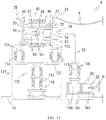
- FIG. 13 is a cross-sectional view of the high-voltage resistant switch 5 of a complex type switch 1 according to this embodiment.
- This embodiment basically employs the same structure as that of the first embodiment. Hence, only the difference from the first embodiment will be explained, and the same component as that of the first embodiment will be denoted by the same reference numeral, and the detailed explanation thereof will be omitted.
- the member corresponding to the support 18 of the high-voltage resistant switch 5 in the first embodiment is a support 111.
- This support 111 is installed between the base 16 that fix the high-voltage resistant switch 5 and the pressure container 17 in the high-voltage status, like the support 18 of the first embodiment.
- the support 111 mechanically supports the pressure container 17, and ensures the insulation distance between the base 16 and the pressure container 17.
- the support 111 includes a large-size support insulator 112, small-size support insulators 113, 114, an insulator connection 115, a support structure 116, and metal fittings 117, 118.
- the large-size support insulator 112 and the small-size support insulators 113, 114 are support beams that have both metal ends insulated by an insulator.
- the insulator connection 115 is a metal block that has connection portions to the support insulators disposed at three locations in a Y shape.
- the respective one ends of the large-size support insulator 112 and the small-size support insulators 113, 114 are connected to the insulator connection 115, and thus a support insulator 119 in a Y shape is formed.
- the support structure 116 is a metal pedestal, and is fixed to the base 16.
- the support structure 116 is also fixed to the other end of the large-size support insulator 112 corresponding to the leg part of the Y-shaped support insulator 119 standing upright.
- the other ends of the small-size support insulators 113, 114 corresponding to the arm parts of the Y-shape are connected to the metal lids 22, 23 via the metal fittings 117, 118.
- Such structure enables the support 111 to structurally stably support the pressure container 17.
- the respective dielectric strengths of the large-size support insulator 112, the small-size support insulators 113 and 114 are defined as A, B, and C
- the lengths of the large-size support insulator 112, the small-size support insulators 113, and 114 are designed in such way that A+B and A+C are equal to or longer than the insulation distance between the pressure container 17 and the ground.
- These lengths are also designed in such way that B+C is equal to or longer than the insulation distance between both ends of the pressure container 17.
- the Y-shaped support insulator 119 that includes the large-size support insulator 112 and the small-size support insulators 113, 114 is applied for the support 111 of the high-voltage resistant switch 5.
- This enables reducing of the number of applied large-size support insulators.
- the large-size support insulator 112 ensures the most part of the dielectric strength between the pressure container 17 and the ground, and the small-size support insulators 113, 114 ensure the dielectric strength between both ends of the pressure container 17.
- FIG. 14 is a cross-sectional view of the high-voltage resistant switch 5 of the complex type switch 1 according to this embodiment.
- This embodiment basically employs the same structure as that of the fourth embodiment. Hence, only the difference between the fourth embodiment will be explained, and the same component as that of the fourth embodiment will be denoted by the same reference numeral, and the detailed explanation thereof will be omitted.
- the member corresponding to the support 111 of the high-voltage resistant switch 5 in the fourth embodiment is a support 121.
- the support 121 is installed between the base 16 that fix the high-voltage resistant switch 5 and the pressure container 17 in the high-voltage status, like the support 111 of the fourth embodiment.
- the support 121 mechanically supports the pressure container 17, and ensures the insulation distance between the base 16 and the pressure container 17.
- the support 121 of the embodiment includes the large-size support insulator 112, the small-size support insulators 113, 114, an insulator connection plate 122, the support structure 116, and metal fittings 123, 124.
- the large-size support insulator 112 and the small-size support insulators 113, 114 are support beams that have both metal ends insulated by an insulator.
- the large-size support insulator 112 is longer than the small-size support insulators 113, 114.
- the insulator connection plate 122 is a metal plate disposed horizontally.
- the insulator connection plate 122 has two connections for the small-size support insulators 113, 114 on the upper surface, and a connection for the large-size support insulator 112 on the lower surface.
- the lower surface of the insulator connection plate 122 is connected to the upper end of the large-size support insulator 112, and the upper surface of the insulator connection plate 122 is connected to the lower ends of the small-size support insulators 113, 114, thereby forming a fork-shape support insulator 125.
- the support structure 116 is a metal pedestal, and is fixed to the base 16.
- the lower end of the large-size support insulator 112 that corresponds to the leg part of the fork-shape support insulator 125 is fixed to the support structure 116.
- the upper ends of the small-size support insulators 113, 114 that correspond to the arm parts of the fork-shape support insulator 125 are connected to the metal lids 22, 23 via the metal fittings 123, 124.
- Such structure enables the support 121 to support the pressure container 17 structurally stable.
- the dielectric strengths of the large-size support insulator 112, the small-size support insulators 113 and 114 are defined as A, B, and C
- the lengths of the large-size support insulator 112, the small-size support insulators 113, and 114 are designed in such way that A+B and A+C are equal to or longer than the insulation distance between the pressure container 17 and the ground.
- these lengths are also designed in such way that B+C is equal to or longer than the insulation distance between both ends of the pressure container 17.
- the fork-shape support insulator 125 that includes the large-size support insulator 112, the small-size support insulators 113, 114 is applied to the support 121 of the high-voltage resistant switch 5.
- the numbers of applied large-size support insulators is reduced.
- the large-size support insulator 112 ensures the most part of the dielectric strength between the pressure container 17 and the ground, and the small-size support insulators 113, 114 ensure the dielectric strength between both ends of the pressure container 17. Hence, the numbers of applied large-size support insulators for a single switch is reduced, thus reducing the manufacturing costs of the switch.
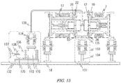
- FIG. 15 is a cross-sectional view illustrating an entire structure of the complex type switch 1 according to this embodiment.
- This embodiment basically employs the same structure as the first embodiment. Hence, only the differences between the first embodiment will be explained, and the same component of the first embodiment will be denoted by the same reference numeral, and the detailed explanation thereof will be omitted.
- the complex type switch 1 of the embodiment has no insulated wiring 6 that connects the vacuum switch 3 and the high-voltage resistant switch 5 in the first embodiment, and has the direction of the vacuum switch 3 in left-right reverse.
- the actuation unit 10 of the vacuum switch 3 and the actuation unit 20 of the high-voltage resistant switch 5 are disposed to face with each other.
- connection side of the support 8 to the metal lid 12 and the connection side of the support 18 to the metal lid 22 are unified by a single common support 131.
- the common support 131 mechanically supports the pressure containers 7, 17, and ensures the respective insulation distances between the base 16 and the pressure container 7, and between the base 16 and the pressure container 17.
- the power supply 11, 21 are unified into a single power supply 132.
- the common support 131 includes a support insulator 133, a support structure 134, and metal fittings 34, 53, 135.
- the support structure 134 is a metal pedestal, and is fixed to the base 16.
- the support insulator 133 is a support beam that has both metal ends insulated by an insulator.
- the one end of the support insulator 133 is fixed to the support structure 134.
- the other end of the support insulator 134 is connected to the metal lid 12 via the metal fittings 135, 34, and also the metal lid 22 via the connection metal fittings 135, 53.
- the support insulator 30 and the support structure 32 of the support 8 and the support insulator 50 and the support structure 52 of the support 18 in the first embodiment are unified into the single support insulator 133 and the single support structure 134, respectively, and are shared via the metal fitting 135.
- the common support 131 structurally stably supports the one ends of the pressure containers 7, 17.
- the length of the support insulator 133 is designed to be longer than the insulation distance between the groundings (support structures) of the pressure containers 7, 17.
- the power supply 132 includes a transformer 136, a bus line 137, a pressure container 173, and an insulator tube 174.
- the transformer 136 and the pressure container 173 are fixed to the base 16 via the support structure 175.
- the opening of the container of the transformer 136 is fixed to the one opening of the pressure container 173.
- the other opening of the pressure container 173 is fixed to the opening of the insulator tube 174.
- the transformer 136, the pressure container 173, and the insulator tube 174 share an internal space 176 that is sealed and filled with an insulative medium.
- the filled insulative medium is same as the one explained above.
- the primary side of the transformer 136 is connected to the bus line 137 via an insulated wiring 138.
- the secondary side of the transformer 136 is connected to an insulated wiring 139.
- the insulated wiring 139 passes through the internal space 176, passes through the upper-side end of the insulator tube 174, and is connected to both of the control device 39 of the actuation unit 10 and the control device 58 of the actuation unit 20.
- Sealers that are unillustrated elastic packing materials are provided at the transformer 136 and the insulator tube 174 in which the insulated wirings 138, 139 pass through, and thus the gas-tightness of the internal space 176 is maintained.
- the dielectric strength between the primary and secondary sides of the transformer 136 and the dielectric strength between both ends of the insulator tube 174 are designed to be larger than the required dielectric strength between the pressure container 7 and the ground.
- the bus line 137 is connected to an unillustrated power supply source.
- the power supplied via the bus line 137 is boosted by the transformer 136 up to the voltage required to drive the actuation units 10, 20, and the boosted voltage is supplied thereto.
- the power supply 132 supplies the power to the actuation units 10, 20 that have respective voltages to ground in a high-voltage status without any short-circuit to the ground.
- the embodiment as explained above achieves the following actions and effects. That is, according to the embodiment, since the numbers of supports and power supplies are reduced in comparison with the first embodiment, the manufacturing costs are reduced.
- the single common support 131 simultaneously supports the pressure containers 7, 17. That is, the plurality of switches share the common support 131. Hence, the numbers of support insulators and support structures applied to the support of the complex type switch 1 are reduced, and thus the manufacturing costs are reduced.
- the power supply is enabled by the single power supply 132. That is, the plurality of switches share the power supply 132. Hence, the number of power supplies applied to the complex type switch 1 is reduced, and thus the manufacturing costs are reduced.
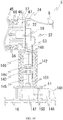
- FIG. 16 is a cross-sectional view of the high-voltage resistant switch 5 of the complex type switch 1 according to this embodiment.
- This embodiment basically employs the same structure as the first embodiment. Hence, only the difference between the first embodiment will be explained, and the same component of the first embodiment will be denoted by the same reference numeral, and the detailed explanation thereof will be omitted.
- the high-voltage resistant switch 5 of the complex type switch 1 includes, instead of a power feeder of the first embodiment that is the power supply 21, a power supply 141.
- a part corresponding to the support insulator 49 of the first embodiment is a support insulator tube 142 that has a sealed internal space.
- This sealed internal space of the support insulator tube 142 is filled with an insulative medium.
- the filled insulative medium is the same as the one as explained above.
- the power supply 141 includes a power feeding coil 143, a power receiving coil 144, a power-feeding-coil support 145, a power-receiving-coil support 146, a coil exciting device 147, and a bus line 148.
- the power feeding coil 143 and the power receiving coil 144 are coils for power demand and supply, and are disposed inside the support insulator tube 142 coaxially in the vertical direction.
- the power feeding coil 143 and the power receiving coil 144 face each other to be apart from each other by the insulation distance.
- the power receiving coil 144 is connected to the control device 58 of the actuation unit 20 via an insulated wiring 149.
- the power-feeding-coil support 145 is a bar-shape support member that has one end fixed to the power feeding coil 143. The other end of the power-feeding-coil support 145 is fixed to the suppor-structure-51 side in the support insulator tube 142.
- the power-receiving-coil support 146 is a bar-shape support member that has one end fixed to the power receiving coil 144. The other end of the power-receiving-coil support 146 is fixed to the pressure-container-17 side in the support insulator tube 142.
- the coil exciting device 147 is fixed to the base 16, and is connected to the power feeding coil 143 via an insulated wiring 151.
- the bus line 148 is connected to an unillustrated power supply source, and is connected to the coil exciting device 147 via an insulated wiring 150.
- the coil exciting device 147 excites the power feeding coil 143 by power supplied from the bus line 148, and produces an induced current to the power receiving coil 144. Hence, power is supplied to the actuation unit 20. In addition, the coil exciting device 147 controls the power to be supplied to the power feeding coil 143 to make the induced current continuously flow through the power receiving coil 144. That is, the power supply 141 is capable of supplying power to the actuation unit 20 that has the voltage to ground in a high-voltage status without any short-circuit to the ground.
- the insulated wirings 149, 150 pass through the support insulator tube 142, and a sealer that is an unillustrated elastic packing material is provided at each passing location, and thus the gas-tightness of the sealed space is maintained.
- the embodiment as explained above achieved the following actions and effects. That is, a part of the power supply 141 is downsized in comparison with the first embodiment.
- the high-voltage resistant switch 5 of the complex type switch 1 utilizes the power supply 141 that is capable of supplying power at remote two sites by electromagnetic induction. Hence, a power supply to the actuation unit 20 that has the voltage to ground in a high-voltage status is enabled without any short-circuit to the ground.
- the power supply 141 has the power feeding coil 143 and the power receiving coil 144 placed in the support insulator tube 142 in which the insulative medium is filled, thereby downsizing the power supply 141.
Landscapes
- High-Tension Arc-Extinguishing Switches Without Spraying Means (AREA)
- Gas-Insulated Switchgears (AREA)
- Driving Mechanisms And Operating Circuits Of Arc-Extinguishing High-Tension Switches (AREA)
Abstract
Description
- Embodiments of the present disclosure relate to a multi-point breaking complex type switch that connects and disconnects a plurality of contacts.
- High-voltage switches breaking a fault current are required to certainly break various currents from a small current to a large current. As for the large current, in particular, the following two current breaking performance must be achieved.
- (1) Breaking Short-range Line Fault (SLF) current As for this, the switches must have a performance capable of coping with a voltage at the beginning of the rising of the voltage (transient recovery voltage) immediately after current zero, namely, a voltage in a triangular waveform which has keen change rate despite its low absolute value.
- (2) Breaking Breaker Terminal short-circuit Fault (BTF) current
- As for this, the switches must have a performance capable of coping with an applied voltage which has a gradual initial rising of the transient recovery voltage but with an absolute value becoming high at the time of termination.
- In recent years, puffer-type switches are widely adopted. This type of switches has one circuit breaker having a contact that can be connected and disconnected, placed in a pressure container in which SF6 gas as an insulation gas is filled. At the time of current breaking, the insulation gas is blown to the contact to extinguish an arc. In this scheme, it is necessary to accomplish both of the two current breaking performance by a single switch.
- In addition, switches achieving the above two current breaking performance by connecting circuit breakers respectively dedicated to each circuit breaking performance are also in development. That is, this type of switches has a plurality of circuit breakers with each circuit breaker bearing an individual current breaking performance. This type of switches has an internal space of the single pressure container divided into two spaces, and the circuit breaker placed in each divided space.
- That is, a puffer-type circuit breaker with an excellent BTF breaking performance is placed in one of the divided internal space, and a puffer-type circuit breaker with an excellent SLF breaking performance is placed in the other divided internal space. In addition, both circuit breakers are electrically connected in series.
- Patent Document 1:
JP 2003-348721 A - As explained above, in switches that have circuit breakers respectively dedicated to the two current breaking performance connected to each other each circuit breaker has a contact that can be connected and disconnected. However, since an actuator which is a single actuation unit performs the current breaking action and the input action for all contacts, the load of the actuation unit will be heavy. This restricts the type and size of the actuation unit, and when it is difficult to increase the operation energy, the current breaking time becomes long.
- Embodiments of the present disclosure have been proposed in order to address the foregoing technical problems of conventional technologies, and the objective is to provide a complex type switch which is capable of easily achieve a plurality of current breaking performance required for a high-voltage switch, and has a short current breaking time.
- A complex type switch according to an embodiment of the present disclosure is proposed to achieve the above objective, and includes the following features:
- (1)at least two switches connected in series;
- (2) at least one of the switches is a vacuum switch that has a vacuum valve at a contact part;
- (3)at least one of the switches is a high-voltage resistant switch that has a contact part that has a larger dielectric strength than the vacuum switch;
- (4)the high-voltage resistant switch and the vacuum switch each include the following features:
- (4-1) a sealed container that is filled with an insulative medium, and has the contact therein;
- (4-2)a support maintaining an electrical insulation to a ground while supporting the sealed container;
- (4-3)an actuation unit driving a movable electrode of the contact part; and
- (4-4) a power supply supplying power to the actuation unit, and
- (5) the high-voltage resistant switch further includes the following feature:
- (5-1) the actuation unit resistant and the movable electrode of the contact part connected to the actuation unit is equipotential.
-
-
FIG. 1 is a cross-sectional view illustrating an entire structure of a complex type switch according to a first embodiment in a input status; -
FIG. 2 is a cross-sectional view illustrating an entire structure of the complex type switch according to the first embodiment in a current breaking status; -
FIGS. 3A and 3B are partially enlarged cross-sectional views ofFIG. 1 , whereFIG. 3A illustrates a vacuum switch, andFIG. 3B illustrates a high-voltage resistant switch; -
FIGS. 4A and 4B are partially enlarged cross-sectional views ofFIG. 2 , whereFIG. 4A illustrates a vacuum switch, andFIG. 4B illustrates a high-voltage resistant switch; -
FIG. 5 is a partially enlarged cross-sectional view illustrating a vacuum switch according to a second embodiment in a input status; -
FIG. 6 is a partially enlarged cross-sectional view illustrating the vacuum switch according to the second embodiment in a current breaking status; -
FIG. 7 is a partially enlarged cross-sectional view ofFIG. 5 ; -
FIG. 8 is a partially enlarged cross-sectional view ofFIG. 6 ; -
FIG. 9 is a cross-sectional view illustrating an entire structure of a complex type switch according to a third embodiment in a input status; -
FIG. 10 is a cross-sectional view illustrating the entire structure of the complex type switch according to the third embodiment in a current breaking status; -
FIG. 11 is a partially enlarged cross-sectional view ofFIG. 9 ; -
FIG. 12 is a partially enlarged cross-sectional view ofFIG. 10 ; -
FIG. 13 is a cross-sectional view illustrating a high-voltage resistant switch according to a fourth embodiment; -
FIG. 14 is a cross-sectional view illustrating a high-voltage resistant switch according to a fifth embodiment; -
FIG. 15 is a cross-sectional view illustrating an entire structure of a complex type switch according to a sixth embodiment; and -
FIG. 16 is a partially enlarged cross-sectional view illustrating a high-voltage resistant switch according to a seventh embodiment. - A structure of a complex type switch according to a first embodiment will be explained with reference to
FIGs. 1-4 .FIGs. 1, 2 are cross-sectional views illustrating an entire structure of the complex type switch in this embodiment.FIG. 1 illustrates an input status, andFIG. 2 illustrates a current breaking status.FIG. 3 is a partially enlarged cross-sectional views ofFIG. 1 , andFIG. 4 is a partially enlarged cross-sectional view ofFIG. 2 . - First of all, the entire structure according to this embodiment will be explained with reference to
FIGs. 1, 2 . Acomplex type switch 1 in the present embodiment includes avacuum switch 3 and a high-voltageresistant switch 5. Thevacuum switch 3 is a switch that includes avacuum valve 2 as a contact. The high-voltageresistant switch 5 is a switch that includes acontact 4 which has a larger dielectric strength than that of thevacuum switch 3. Thevacuum switch 3 and the high-voltageresistant switch 5 are arranged side by side in the horizontal direction on a base 16 that is an installation surface, and are electrically connected in series via aninsulated wiring 6. - The
vacuum switch 3 includes apressure container 7, asupport 8, acontact part 9, anactuation unit 10, and apower supply 11. Thepressure container 7 is a cylindrical sealed container formed of an insulator and a metal. The openings at both ends of the insulator that is a barrel part of thepressure container 7 are sealed bymetal lids metal lids plates metal lids vacuum switch 3 is connected to an unillustrated bus line via the current-carryingplate 14, and is connected to the high-voltageresistant switch 5 from the current-carryingplate 15 via theinsulated wiring 6. Theinsulated wiring 6 is a wiring that has an ensured insulation from the exterior by, for example, insulative cover. - The
support 8 supports thepressure container 7, and ensures the insulation relative to the ground. Thesupport 8 is installed between the base 16 that fastens thevacuum switch 3, and thepressure container 7 in a high-voltage status. Hence, thesupport 8 mechanically supports thepressure container 7, and ensures the insulation distance between the base 16 and thepressure container 7. That is, thesupport 8 ensures the electrical insulation between thepressure container 7 and the ground surface. - The
contact part 9 includes thevacuum valve 2 and ashield 65. Thecontact part 9 is placed in thepressure container 7, and is connected to themetal lids pressure container 7 directly or via theactuation unit 10. - The
actuation unit 10 is a mechanism that actuates thevacuum valve 2 of thecontact part 9. Theactuation unit 10 is connected to the end of thepressure container 7, and applies kinetic energy to thevacuum valve 2 of thecontact part 9, thereby actuating thevacuum valve 2 to connect, disconnect, close and open. This changes the conduction status of thevacuum switch 3. Thepower supply 11 is installed on thebase 16, and is a power supply source to actuate theactuation unit 10. - The high-voltage
resistant switch 5 includes apressure container 17, asupport 18, acontact part 19, anoperation part 20, and apower supply 21. Thepressure container 17 is a cylindrical sealed container formed of an insulator and a metal. The openings at both ends of the insulator that is a barrel part of thepressure container 17 are sealed bymetal lids metal lids plates metal lids resistant switch 5 is connected to thevacuum switch 3 from the current-carryingplate 24 via theinsulated wiring 6, and is connected to the unillustrated bus line via the current-carryingplate 25. - The
support 18 supports thepressure container 17, and ensures the insulation relative to the ground. Thesupport 18 is installed between the base 16 that fix the high-voltageresistant switch 5, and thepressure container 17 in a high-voltage status. Thesupport 18 mechanically supports thepressure container 17, and ensures the insulation distance between the base 16 and thepressure container 17. That is, thesupport 18 ensures the electrical insulation between thepressure container 17 and the ground surface. - The
contact part 19 includes acontact 4 and shields 66, 67. Thecontact part 19 is placed in thepressure container 17, and is connected to themetal lids pressure container 17 directly or via theactuation unit 20. - The
actuation unit 20 is a mechanism that actuates thecontact 4 of thecontact part 19. Theactuation unit 20 is connected to the end of thepressure container 17, applies kinetic energy to thecontact 4 of thecontactor 19, thereby actuating thecontact 4 to connect, disconnect, close and open. This changes the conduction status of the high-voltageresistant switch 5. Thepower supply 21 is installed on thebase 16, and is a power supply source to actuate theactuation unit 20. - When the
complex type switch 1 as explained above in a input status, as illustrated inFIG. 1 , a current introduced from the current-carryingplate 14 flows through themetal lid 12, theactuation unit 10, thevacuum valve 2, themetal lid 13, and the current-carryingplate 15. In addition, the current flows through, the current-carryingplate 24, themetal lid 22, theactuation unit 20, thecontact 4, and themetal lid 23 in sequence, and is derived to the current-carryingplate 25, via theinsulated wiring 6. In addition, when thecomplex type switch 1 is in a current breaking status, as illustrated inFIG. 2 , thevacuum valve 2 of thevacuum switch 3 and thecontact 4 of the high-voltageresistant switch 5 are opened and disconnected, and thus the current will be broken. - The detailed structure according to the embodiment will be explained below.
- First, the
pressure container 7, thesupport 8, thecontact part 9, theactuation unit 10 and thepower supply 11 that form thevacuum switch 3 generally explained above will be explained with reference toFIGs. 3A and4A . Note thatFIGs. 3A ,4A are enlarged cross-sectional views of thevacuum switch 3.FIG. 3A illustrates the input status, andFIG. 4A illustrates the current breaking status. - The
pressure container 7 includes aninsulator tank 26 and themetal lids insulator tank 26 has aninsulator tube 27 having both ends opened as a barrel part, andmetal flanges metal flanges metal lids - An
internal space 68 of thepressure container 7 is in a sealed condition. Thisinternal space 68 is filled with an insulative medium. An exemplary insulative medium is a sulfur hexafluoride gas (SF6 gas), carbon dioxide, nitrogen, dry air, a mixture gas thereof, or an insulative oil. In the embodiment, the SF6 gas is applied. - The
support 8 includessupport insulators support structures 32, 33, andmetal fittings support structures 32, 33 are metal pedestal that stands upright, and have lower ends fixed to thebase 16. The support insulators 30, 31 are support beams that have both metal ends insulated by insulator. The lower ends of thesupport insulators support structures 32, 33. The upper ends of thesupport insulators metal lids metal fittings - Hence, the
support 8 supports thepressure container 7 structurally stable. In addition, the lengths of thesupport insulators pressure container 7 and the ground (support structure).[0029] (3) Contact part - The
contact part 9 includes thevacuum valve 2 and theshield 65. Thevacuum valve 2 includes a fixedelectrode 36, amovable electrode 37, avacuum container 2a, and abellows 2b. The fixedelectrode 36 is directly fixed to themetal lid 13. Themovable electrode 37 is connected to themetal lid 12 via adrive device 38 of theactuation unit 10. - The
vacuum container 2a is a container which contains therein the fixedelectrode 36 and themovable electrode 37, and is formed of an insulator sealed in a vacuum condition. Thebellows 2b is a flexible stretchable member that attaches themovable electrode 37 to thevacuum container 2a to be movable while maintaining airtight condition. Note that the gas pressure of theinternal space 68 is equal to or lower than the gas pressure of aninternal space 69 explained later and equal to or higher than the atmospheric pressure. This is the pressure that thebellows 2b can withstand. Theshield 65 is disposed so as to ease the concentration of the electric field around thevacuum valve 2, and is connected to themetal lid 12. - The
actuation unit 10 includes thedrive device 38, and acontrol device 39. Thedrive device 38 is fixed to themetal lid 12 inside thepressure container 7. The drive shaft of thedrive device 38 is connected to themovable electrode 37, and drives thevacuum valve 2 so as to be freely connected and disconnected. In addition, as for the connection between thedrive device 38 and themovable electrode 37, not an insulation material but a conductive material is applied. This achieves an equipotential. As for the conductive material, a metal material with high conductivity is preferably used. Thecontrol device 39 is fixed to themetal lid 12 outside thepressure container 7, and is connected to thedrive device 38 via aninsulated wiring 40 that passes through themetal lid 12. Hence, thecontrol device 39 adjusts the power supplied to thedrive device 38, thereby controlling the action of thedrive device 38. - The
actuation unit 10 pushes and pulls themovable electrode 37 linearly, so as to connect, disconnect, open and close the fixedelectrode 36, by applying drive force to the mechanically connectedmovable electrode 37. Note that the action of theactuation unit 10 may be started by, for example, when thecontrol device 39 receives an instruction signal from an unillustrated signal output device installed outside thevacuum switch 3. In addition, a sealer that includes an unillustrated elastic material is provided at themetal lid 12 of thepressure container 7 in which theinsulated wiring 40 passes through, and thus the gas-tightness of theinternal space 68 is maintained. - The
power supply 11 includes atransformer 41, thebus line 42, apressure container 161, and aninsulator tube 162. The container of thetransformer 41 and thepressure container 161 are fixed to thebase 16 via thesupport structure 163. The opening of the container of thetransformer 41 is fixed to the one opening of thepressure container 161. On the other hand, the other opening of thepressure container 161 is fixed to the opening of theinsulator tube 162. Thetransformer 41, thepressure container 161, and theinsulator tube 162 share aninternal space 164 that is sealed and filled with an insulative medium. The filled insulative medium is the same as the one explained above. The primary side of thetransformer 41 is connected to thebus line 42 via aninsulated wiring 43. In addition, the secondary side of thetransformer 41 is connected to aninsulated wiring 44. Theinsulated wiring 44 passes through theinternal space 164, passes through the end of theinsulator tube 162 at the actuation unit10 side, and is connected to thecontrol device 39 of theactuation unit 10. Sealers including unillustrated elastic materials are provided to thetransformer 41 and theinsulator tube 162 in which theinsulated wirings internal space 164 is maintained. The dielectric strength between the primary and secondary sides of thetransformer 41 and the dielectric strength between both ends of theinsulator tube 162 are designed to be larger than the required dielectric strength between thepressure container 7 and the ground. Thebus line 42 is connected to an unillustrated power supply source. - The power supplied from the power supply source via the
bus line 42 is boosted by thetransformer 41 up to the necessary voltage to drive theactuation unit 10, and the boosted voltage is supplied thereto. That is, thepower supply 11 supplies the power to theactuation unit 10 that has a voltage to ground in a high-voltage status without any short-circuit to the ground. - Next, the
pressure container 17, thesupport 18, thecontact part 19, theactuation unit 20, and thepower supply 21 that form the high-voltageresistant switch 5 generally explained above will be explained with reference toFIGs. 3B ,4B . Note thatFIGs. 3B ,4B are enlarged cross-sectional views illustrating the high-voltageresistant switch 5, andFIG. 3B illustrates an input status, andFIG. 4B illustrates a current breaking status. - The
pressure container 17 includes aninsulator tank 45 and themetal lids insulator tank 45 has aninsulator tube 46 having both ends opened as a barrel part, andmetal flanges metal flanges metal lids - The
internal space 69 of thepressure container 17 is in a sealed condition, and is filled with the insulative medium. The insulative medium to be filled is same as the one as explained above. - The
support 18 includessupport insulators support structures metal fittings support structures base 16. The support insulators 49, 50 are support beams that have both metal ends insulated by insulator. The lower ends of thesupport insulators support structures support insulators metal lids metal fittings - Hence, the
support 18 supports thepressure container 17 structurally stable. In addition, the lengths of thesupport insulators pressure container 17 and the ground (support structure). This ensures the electrical insulation of thepressure container 17 to the ground surface. - The
contact part 19 includes thecontact 4, and theshields contact 4 includes a fixedelectrode 55 and amovable electrode 56. Thestationary electrode 55 is directly fixed to themetal lid 23. Themovable electrode 56 is connected to themetal lid 22 via adrive device 57 of theactuation unit 20. Theshields contact 4, and are connected to themetal lids - The
actuation unit 20 includes thedrive device 57, and acontrol device 58. Thedrive device 57 is fixed to themetal lid 22 inside thepressure container 17. The drive shaft of thedrive device 57 is connected to themovable electrode 56, and drives thecontact 4 to be freely connected and disconnected. In addition, as for the connection between thedrive device 57 and themovable electrode 56, not an insulation material but a conductive material is applied. This achieves an equipotential. As for the conductive material, a metal material with high conductivity is preferably used. Thecontrol device 58 is fixed to themetal lid 22 outside thepressure container 17, and is connected to thedrive device 57 via aninsulated wiring 59 that passes through themetal lid 22. Hence, thecontrol device 58 adjusts the power supplied to thedrive device 57, thereby controlling the action of thedrive device 57. - The
actuation unit 20 pushes and pulls themovable electrode 56 linearly, so as to connect, disconnect, open and close the fixedelectrode 55, by applying drive force to the mechanically connectedmovable electrode 56. Note that the action of theactuation unit 20 may be started by, for example, when thecontrol device 58 receives an instruction signal from an unillustrated signal output device installed outside the high-voltageresistant switch 5. - In addition, a sealer that includes an unillustrated elastic material provided at the
metal lid 22 of thepressure container 17 in which theinsulated wiring 59 passes through, and thus the gas-tightness of theinternal space 69 is maintained. - The
power supply 21 includes atransformer 60, thebus line 61, apressure container 165, and aninsulator tube 166. The container of thetransformer 60 and thepressure container 165 are fixed to thebase 16 via thesupport structure 167. The opening of the container of thetransformer 60 is fixed to the one opening of thepressure container 165. On the other hand, the other opening of thepressure container 165 is fixed to the opening of theinsulator tube 166. Thetransformer 60, thepressure container 165, and theinsulator tube 166 share aninternal space 168 that is sealed and filled with an insulative medium. The filled insulative medium is the same as the one explained above. The primary side of thetransformer 60 is connected to thebus line 61 via aninsulated wiring 62. In addition, the secondary side of thetransformer 60 is connected to aninsulated wiring 63. Theinsulated wiring 63 passes through theinternal space 168, passes through the end of theinsulator tube 166 at the actuation unit-20 side, and is connected to thecontrol device 58 of theactuation unit 20. Sealers including unillustrated elastic materials are provided to thetransformer 60 and theinsulator tube 166 in which theinsulated wirings internal space 168 is maintained. The dielectric strength between the primary and secondary sides of thetransformer 60 and the dielectric strength between both ends of theinsulator tube 166 are designed to be larger than the required dielectric strength between thepressure container 17 and the ground. Thebus line 61 is connected to an unillustrated power supply source. - The power supplied from the power supply source via the
bus line 61 is boosted by thetransformer 60 up to the necessary voltage to drive theactuation unit 20, and the boosted voltage is supplied thereto. That is, thepower supply 21 supplies the power to theactuation unit 20 that has a voltage to ground in a high-voltage status without any short-circuit to the ground. - The action according to the embodiment explained above will be explained with reference to the input status and the current breaking status, separately. Note that
FIGs. 1 ,3A, 3B illustrate the input status, andFIGs. 2 ,4A, 4B illustrate the current breaking status. - First, when the
complex type switch 1 is in the input status, the current derived from the current-carryingplate 14 flows through themetal lid 12, thedrive device 38, themovable electrode 37, the fixedelectrode 36, themetal lid 13, and the current-carryingplate 15. Next, the current flows from the current-carryingplate 15 to, via theinsulated wiring 6, the current-carryingplate 24, themetal lid 22, thedrive device 57, themovable electrode 56, the fixedelectrode 55, and themetal lid 23 in sequence, and is derived to the current-carryingplate 25. - On the other hand, when a current breaking command is given from the exterior of the
complex type switch 1, driving force is applied to themovable electrodes drive devices movable electrodes electrodes - More specifically, in the
vacuum switch 3, themovable electrode 37 of thevacuum valve 2 are opened and disconnected from the fixedelectrode 38. During this action, an arc including evaporated particles from the electrode and electrons is produced between themovable electrode 37 and the fixedelectrode 38. However, since the interior of thevacuum valve 2 is in a high vacuum condition, the substances forming the arc are diffused, and are unable to maintain its form, thus being dissipated. Hence, the flowing current is broken. - On the other hand, in the high-voltage
resistant switch 5, themovable electrode 56 of thecontact 4 is opened and disconnected from the fixedelectrode 55, and an arc is produced between those electrodes, but the arc will be extinguished by ensuring the insulation distance between those electrodes. - During this current breaking action, in the
internal space 69 of the high-voltageresistant switch 5, the separation gas of the SF6 gas produced by the arc is produced. This separation gas has an action of corroding the surface layer of thevacuum container 2a of thevacuum valve 2 formed of the insulator. However, since thevacuum container 2a is placed in thepressure container 7 of thevacuum switch 3, the corrosion thereof by the separation gas produced in theinternal space 69 is preventable. - The
bellows 2b of thevacuum valve 2 may have a pressure resistance not so high. In the embodiment, the gas pressure in theinternal space 68 is set to be equal to or lower than the gas pressure in theinternal space 69 and equal to or higher than the atmospheric pressure which is a pressure thebellows 2b can resist. Accordingly, thebellows 2b of theinternal space 68 is protected while the dielectric strength at thecontact 4 in theinternal space 69 is ensured. - As explained above, according to the embodiment, during the current breaking action, the
vacuum switch 3 bears the keen transient recovery voltage in the SLF breaking performance, and the high-voltageresistant switch 5 that has a high dielectric strength bears a high transient recovery voltage in the BTF breaking performance. Hence, both breaking performances are easily achieved. - The embodiment explained above has the following effects.
- (1) Since the plurality of switches is provided with each having the actuation unit that drives the contact part, a load per an actuation unit is reduced, enabling a fast-speed opening and disconnecting of the contact. That is, since the
actuation unit 10 that drives thecontact part 9 of thevacuum switch 3 and theactuation unit 20 that drives thecontact part 19 of the high-voltageresistant switch 5 are provided, the respective loads to theactuation unit 10 and theactuation unit 20 are reduced, enabling a fast-speed opening and disconnecting. - (2) In the plurarity of switches, since at least one of the switches handle the SLF breaking performance, and at least one of the switches handle the BTF breaking performance, both of the performances are easily achieved. That is, the
vacuum switch 3 that includes thevacuum valve 2 is applied as one switch, and the high-voltageresistant switch 5 that has a larger dielectric strength than that of thevacuum valve 2 is applied as one switch. Hence, thevacuum switch 3 is capable of coping with the keen transient recovery voltage in the SLF breaking performance during the breaking action. In addition, the high-voltageresistant switch 5 that has a high dielectric strength is capable of coping with the high transient voltage in the BTF breaking performance. - (3) Since the plurality of switches has the drive device and the movable electrode in equipotential, it is unnecessary to ensure the insulation distance between the drive device and the movable electrode. Accordingly, a connection formed of an insulation material becomes unnecessary. This reduces the weight of a movable component, enabling a fast-speed opening and disconnecting of the contact. That is, the
drive device 38 of theactuation unit 10 of thevacuum switch 3 is equipotential to that of themovable electrode 37, and thedrive device 57 of theactuation unit 20 of the high-voltageresistant switch 5 is equipotential to themovable electrode 56. Therefore, a shorter distance between thedrive device movable electrode
In addition, since the connection formed of an insulation material has a lower rigidity than that of a metal material, in the initial stage of the breaking action, the insulation material would have a large elongation, resulting in a response delay of the movable electrode relative to the action of the drive device. In the embodiment, thecomplex type switch 1 has no such connection formed of the insulation material, and thus a response delay of themovable electrode drive device
Still further, thedrive device 38 is placed in thepressure container 7, and thedrive device 57 is placed in thepressure container 17, the distance between thedrive device movable electrode
Yet still further, since the connection between the drive device and the movable electrode does not pass through the pressure container, a response delay due to a sliding friction between the connection and the pressure container, a gas leakage, and an increase of the number of components due to providing a sealer are preventable. - (4) In the embodiment, in comparison with conventional switches that includes a plurality of puffer-type contact part, the current breaking and the insulation distance are ensured at shorter time , and the current breaking time is reduced. That is, the
vacuum switch 3 has thevacuum valve 2 which includes a contact type contact, and themovable electrode 37 is of light weight. This enables a current breaking action at a quite short time. In addition, the high-voltageresistant switch 5 includes the designatedactuation unit 20 as the puffer type gas contact part. Hence, as a wholecomposite type switch 1, the load per anactuation unit contact 4 to be opened and disconnected at fast speed. Still further, when the high-voltage resistant switch does not have puffer cylinder and nozzle in the movable electrode, in comparison with a puffer type contact, a weight of the driven movable component of thedrive device 57 can be reduced. Hence, thedrive device 57 is capable of driving themovable electrode 56 at faster speed, and thus a time required to ensure the insulation distance is remarkably reduced. - (5) Since a structure is employed in which the contact parts are divided into the individual switches, and the space placing each contact part is independent, those spaces may have a different pressure. More specifically, the gas pressure in the
internal space 68 is set to be equal to or lower than the gas pressure in theinternal space 69, and is equal to or higher than the atmospheric pressure. Hence, the dielectric strength of the contact in theinternal space 69 is ensured, while at the same time, thebellows 2b of theinternal space 68 is protected. In addition, thevacuum container 2a is placed in thepressure container 7. This prevents the separation gas of the SF6 gas produced by an arc in theinternal space 69 from directly contacting thevacuum container 2a of thevacuum valve 2 formed of an insulator, thereby suppressing a corrosion by the separation gas. - A second embodiment will be explained with reference to
FIGs. 5-8 . Note thatFIGs. 5, 6 are enlarged cross-sectional views of thevacuum switch 3 according to the second embodiment, andFIG. 5 illustrates the input status of thevacuum switch 3, andFIG. 6 illustrates the current breaking status of thevacuum switch 3.FIGs. 7, 8 are enlarged cross-sectional views of an electromagneticrepulsion drive device 71 inFIGs. 5, 6 , respectively. - In this embodiment, the basic structure is same as that of the first embodiment. Hence, only the differences between the first embodiment will be explained, and the same part as that of the first embodiment will be denoted by the same reference numeral, and the detailed explanation will be omitted.
- In the embodiment, as the
drive device 38 of theactuation unit 10 for thevacuum switch 3, the electromagneticrepulsion drive device 71 is applied. The electromagneticrepulsion drive device 71 utilizes electromagnetic repulsion force for the drive force of the electrode opening action, and has a high responsiveness in the electrode opening action. This electromagneticrepulsion drive device 71 includes amechanism box 72, a fast-speedelectrode opening unit 73, awiping mechanism unit 74, and aholding mechanism unit 75. Each component will be explained in detail below. - The
mechanism box 72 is a box with a hollow interior which has one end opened at the vacuum-valve-2 side. Asupport 80 that is a wall surface separating themechanism box 72 from the exterior is fixed to the opening of themechanism box 72. Ahole 80a that slidably supports themovable electrode 37 of thevacuum valve 2 is formed in the center of thesupport 80. - The bottom of the
mechanism box 72 opposite to the support-80 side is fixed and connected to the wall surface of themetal lid 12 inside thepressure container 7. The fast-speedelectrode opening unit 73, thewiping mechanism unit 74, and theholding mechanism 75 are placed insuch mechanism box 72. - The fast-speed
electrode opening unit 73 includes amovable shaft 76, anelectromagnetic repulsion coil 77, arepulsion ring 78, and arepulsion ring catcher 79. - The
movable shaft 76 is a bar member coaxially connected to themovable electrode 37 of thevacuum valve 2. Therepulsion ring catcher 79 is an annular member that is fitted in themovable shaft 76 and is integrated therewith. Therepulsion ring 78 is an annular body formed of a good conductor. Therepulsion ring 78 is coaxially fixed to the surface of therepulsion ring catcher 79 at the vacuum-valve-2 side. - The
electromagnetic repulsion coil 77 is a coil formed of a good conductor, and fixed to the surface of thesupport 80 facing therepulsion ring 78. In this case, therepulsion ring 78 is an opposing good conductor that opposes to theelectromagnetic repulsion coil 77. Theelectromagnetic repulsion coil 77 is connected to thecontrol device 39 via theinsulated wiring 40. Thecontrol device 39 is a coil exciter, and excites theelectromagnetic repulsion coil 77 by supplying power via the capacitor built in thecontrol device 39. - That is, the
electromagnetic repulsion coil 77 is excited by the power from thecontrol device 39, produces electromagnetic repulsion force that is repulsive force relative to therepulsion ring 78, and drives themovable shaft 76 in the rightward direction in the figure. Note that exemplary good conductors applied for theelectromagnetic repulsion coil 77 and therepulsion ring 78 are copper, silver, gold, aluminum, and iron. - The
wiping mechanism unit 74 transmits the electromagnetic repulsion force produced by the fast-speedelectrode opening unit 73 to theholding mechanism 75. Thewiping mechanism unit 74 includes aflange 81, acoupling 82, a wipingspring 83, aflange holder 84, and ashock absorber 85. - The
flange 81 is a tabular member in an annular shape engaged coaxially with themovable shaft 76. Thecoupling 82 is a flat plate disposed to face theflange 81, and is fixed to the end of aleg 89a of amovable component 89 explained later. The wipingspring 83 has one end abutted to theflange 81 and another end abutted to thecoupling 82 with pushing force being applied to theflange 81 and thecoupling 82. - The
flange holder 84 is a cylindrical body with a bottom. Theflange holder 84 has an end opposite to the bottom fixed to thecoupling 82 to encircle theflange 81 and the wipingspring 83. Hence, the bottom of theflange holder 84 serves as a stopper for theflange 81. Note that an opening is formed in the bottom of theflange holder 84 in which themovable shaft 76 is inserted in a movable manner. - The
shock absorber 85 is fixed to thecoupling 82. Theshock absorber 85 has an elasticity and a strength capable of absorbing shock from themovable component 89. Hence, theshock absorber 85 suppresses a shock when themovable shaft 76 collides. - The holding
mechanism 75 includes apermanent magnet 86, a circuit-openingspring 87, anelectromagnetic solenoid 88, themovable component 89, and ashock absorber 90. Thesepermanent magnet 86, the circuit-openingspring 87, theelectromagnetic solenoid 88, themovable component 89, and theshock absorber 90 are housed in an apace opposite to the fast-speedelectrode opening unit 73 formed by thesupport 91 and the internal surface of themechanism box 72. Thissupport 91 is a partition wall provided on the internal surface of themechanism box 72 and divides the internal space of themechanism box 72 in the orthogonal direction to the axis. - The
movable component 89 is a ferromagnetic body that has attraction force with thepermanent magnet 86. Themovable component 89 has a cross-section formed in a substantially T shape, has theleg 89a that is an axis inserted in anopening 91a provided in the center of thesupport 91, protruding toward the fast-speedelectrode opening unit 73, and fixed to thecoupling 82. Theleg 89a is slidably supported by theopening 91a of thesupport 91. In addition, abarrel 89c which has a larger diameter than that of theleg 89a and a smaller diameter than that of a spreadingportion 89b is formed at the basal end of theleg 89a relative to the T-shaped spreadingportion 89b of themovable component 89. Theelectromagnetic solenoid 88 to be explained later is provided around thebarrel 89c. - The
permanent magnet 86 is fixed to a wall surface opposite to the fast-speedelectrode opening unit 73 side, of thesupport 91, and faces the both ends 89b of themovable component 89. Thispermanent magnet 86 produces attraction force to a gap of the T-shaped spreadingportion 89b of themovable component 89. Thepermanent magnet 86 and theelectromagnetic solenoid 88 produce thrust force in a direction closing and contacting themovable electrode 37 that forms a contact of thevacuum valve 2, relative to the spreadingportion 89b of themovable component 89. - The circuit-opening
spring 87 is placed between the spreadingportion 89b of themovable component 89 and the wall surface of thesupport 91 where thepermanent magnet 86 is provided, so as to apply pushing force to themovable component 89. The applied circuit-openingspring 87 has the pushing force larger than a total of the self-closing force of thevacuum valve 2 and the attraction force of thepermanent magnet 86 in the circuit opening condition, and has a smaller than the attraction force of thepermanent magnet 86 relative to themovable component 89 in the circuit closing condition. - The
electromagnetic solenoid 88 is a winding formed of a conductive member, and is wound around and fixed to thebarrel 89c of themovable component 89. Theelectromagnetic solenoid 88 is connected to thecontrol device 39 via theinsulated wiring 40 like theelectromagnetic coil 77, has power supplied from the power supply in thecontrol device 39, and can be excited. - The
shock absorber 90 is fixed to the internal surface of themechanism box 72 facing the spreadingportion 89b of themovable component 89. Theshock absorber 90 has an elasticity and a strength capable of absorbing shock from themovable component 89. Hence, theshock absorber 90 suppresses a shock when themovable component 89 collides. - The action according to the embodiment will be explained with reference to the input status and the current breaking status, separately. Note that
FIGs. 5 ,7 illustrate the input status, andFIGs. 6 ,8 illustrate the current breaking status. - First, the input status of the embodiment will be explained. In the input status, the fixed
electrode 36 of thevacuum valve 2 and themovable electrode 37 are in contact with each other at a predetermined load. - The attraction force by the
permanent magnet 86 in the circuit closing direction acting on themovable component 89 is larger than the force by the wipingspring 83 and the circuit-openingspring 87 in the circuit opening direction. Hence, the attraction force by thepermanent magnet 86 causes the spreadingportion 89b of themovable component 89 to compress the circuit-openingspring 87, abuts thesupport 91, and themovable component 89 is in a condition fixed to thesupport 91. - On the other hand, this attraction force causes the
movable electrode 37 to abut the fixedelectrode 36 via themovable shaft 76, and the pushing force in the circuit closing direction is applied by thewiring spring 83. - Hence, the fixed
electrode 36 of thevacuum valve 2 and themovable electrode 37 are in contact with each other by the load from the wipingspring 83, and maintain the input status (circuit closing condition) by the attraction force of thepermanent magnet 86 acting on themovable component 89. - Next, an explanation for an electrode opening action of the electromagnetic
repulsion drive device 71 in the current breaking action of the embodiment will be given. First, in the circuit closing condition in which the fixedelectrode 36 of thevacuum valve 2 and themovable electrode 37 are in contact with each other, an electrode opening instruction is given to thecontrol device 39 from the exterior of the switch. This causes the capacitor of thecontrol device 39 to start supplying the power to theelectromagnetic repulsion coil 77, and thus theelectromagnetic repulsion coil 77 is excited. - Thus, electromagnetic repulsion force is produced between the
electromagnetic coil 77 and therepulsion ring 78, and themovable electrode 37 opens in high-speed in the direction toward the electromagneticrepulsion drive device 71 from the fixedelectrode 36 via therepulsion ring catcher 79 and themovable shaft 76. The direction in which the electrode is opened in thevacuum valve 2 will be hereafter referred to as a circuit opening direction. In addition, the opposite direction will be referred to as a circuit closing direction. - The
movable shaft 76 moves in the circuit opening direction, theflange 81 compresses the wipingspring 83, while colliding theshock absorber 85. At this time, themovable shaft 76 has a reduced bounce in the circuit closing direction by theshock absorber 85, and thecoupling 82 is pushed in the circuit opening direction via the wipingspring 83 and theshock absorber 85. - On the other hand, the power is supplied from the
control device 39 to theelectromagnetic solenoid 88 of theholding mechanism 75 prior to a timing at which themovable shaft 76 pushes in thecoupling 82 in the circuit opening direction. Hence, theelectromagnetic solenoid 88 is excited in the direction in which the magnetic flux of thepermanent magnet 86 is canceled, and the attraction force produced in the gap between the spreadingportion 89b of themovable component 89 and thepermanent magnet 86 is reduced. In this case, themovable component 89 is driven in the circuit opening direction by the pushing force of the circuit-openingspring 87. - Next, when the
flange holder 84 abuts theflange 81 via thecoupling 82, themovable component 89 integrally pulls thecoupling 82, theflange holder 84, and theflange 81, and themovable electrode 37 is further opened via themovable shaft 76. - Subsequently, by the inertial force of the
movable electrode 37 and themovable shaft 76, and the pushing force of the circuit-openingspring 87, themovable electrode 37 is opened and disconnected until a predetermined gap relative to the fixedelectrode 36 is obtained, and themovable component 89 collides theshock absorber 90. This shock is absorbed by theshock absorber 90, and themovable component 89 stops. - Note that a predetermined gap is a necessary gap between the fixed
electrode 36 and themovable electrode 37 to break the current. After the predetermined gap between themovable electrode 37 and the fixedelectrode 36 is obtained, the power supply to theelectromagnetic repulsion coil 77 and theelectromagnetic solenoid 88 is terminated, thereby canceling the excitation thereof. - For example, a capacitor that has accumulated charges may be applied as a power supply source from the
control device 39, so as to release the accumulated charges, and thereby canceling the excitation upon depletion of the accumulated charges. - As other schemes, for example, an unillustrated position sensor may measure the driven distance of the
movable electrode 37, and the excitation may be cancelled by cutting of the power supply after confirming by thecontrol device 39 that themovable electrode 37 has been moved equal to or longer than the predetermined gap. After the excitation cancel, since the pushing force by the circuit-openingspring 87 is larger than the total of the self-closing force by thevacuum valve 2 and the attraction force by thepermanent magnet 86, the contact of thevacuum valve 2 maintains the circuit opening condition. - The embodiment explained above is capable of achieving the following effects in addition to the effects of the first embodiment.
- (1) The drive device of the
vacuum valve 2 is the electromagneticrepulsion drive device 71. Hence, because thevacuum valve 2 has a short movement distance (stroke) for themovable electrode 37 necessary to breaking the current and the moving component is lightweight, a high responsiveness in the electrode opening action is achieved, and thus the required time to break the current is further shortened. - (2) As the electromagnetic
repulsion drive device 71, the fast-speedelectrode opening unit 73 that includes theelectromagnetic repulsion coil 77, thesupport 80 that fix theelectromagnetic repulsion coil 77, therepulsion ring 78 facing theelectromagnetic repulsion coil 77, and therepulsion ring catcher 79 that supports therepulsion ring 78, is provided. By the electromagnetic repulsion force acting between the excitedelectromagnetic repulsion coil 77 and therepulsion ring 78, the electromagneticrepulsion drive device 71 that opens the electrode has a quite fast drive-force rise, thereby achieving an excellent responsiveness in comparison with the drive devices that have a drive source which is spring force and hydraulic pressure. Hence, an excellent SLF breaking performance for a keen transient recovery voltage is achieved. - (3) The electromagnetic
repulsion drive device 71 is provided with a thrust force applier that applies thrust force to themovable electrode 37 of thevacuum valve 2. More specifically, themovable component 89 formed of a ferromagnetic material which is indirectly connected to themovable shaft 76 via thecoupling 82, the wipingspring 83, theflange holder 84, and theflange 81, etc., thepermanent magnet 86, and theelectromagnetic solenoid 88 are provided. This causes the attraction force by thepermanent magnet 86 and the excitedelectromagnetic solenoid 88 to act on themovable component 89, and thus thrust force in the circuit closing direction acting on themovable component 89 and themovable shaft 76 is produced, thereby driving themovable electrode 37 to be in contact with the fixedelectrode 36. - An explanation will be given of a third embodiment with reference to
FIGs. 9-12 . Note thatFIGs. 9, 10 are cross-sectional views illustrating an entire structure of acomplex type switch 1 according to the embodiment, andFIG. 9 illustrates a input status, andFIG. 10 illustrates a current breaking status.FIGs. 11, 12 are respective partially enlarged views of a high-voltageresistant switch 5 inFIG. 9 and FIG. 10 . - The embodiment basically employs the same structure to that of the first embodiment. Hence, only the differences between the first embodiment will be explained, and the same component to that of the first embodiment will be denoted by the same reference numeral, and the detailed explanation thereof will be omitted.
- In the embodiment, an
actuation unit 101 and apower supply 102 are added to thecomplex type switch 1 of the first embodiment. In addition, according to the first embodiment, the fixedelectrode 55 is fixed to themetal lid 23. In this embodiment, however, the electrode corresponding to the fixedelectrode 55 of the first embodiment is movable, and is connected to theactuation unit 101. Hence, in the following explanation, this electrode will be referred to as amovable electrode 105. - The structure of the high-voltage
resistant switch 5 in the embodiment will be explained below. First, theactuation unit 101 includes adrive device 103, and acontrol device 104. Thedrive device 103 is fixed to themetal lid 23 in thepressure container 17, is connected to themovable electrode 105, and drives thecontact 4 to be freely contacted and disconnected. - The
control device 104 is fixed to themetal lid 23 outside thepressure container 17, and is connected to thedrive device 103 via aninsulated wiring 106 that passes through themetal lid 23. Thecontrol device 104 adjusts the power supplied to thedrive device 103, thereby controlling the action of thedrive device 103. - That is, the
actuation unit 101 applies drive force to the mechanically connectedmovable electrode 105 to linearly pushes and pulls themovable electrode 105, thereby causing themovable electrode 105 to connect, disconnect, open, and close relative to themovable electrode 56. - Note that the action of the
actuation unit 101 may be started by, for example, thecontrol device 104 which receives an instruction signal from an unillustrated signal output device installed outside the high-voltageresistant switch 5. In addition, a sealer that is an unillustrated elastic packing material is provided at opening of themetal lid 23 of thepressure container 17 where theinsulated wiring 106 passes through, and thus the gas-tightness of theinternal space 69 is maintained. - The
power supply 102 is a power supplier that supplies power to theactuation unit 101 that has the ground voltage in a high-voltage status, without any short-circuit to the ground. Thepower supply 102 includes atransformer 107, abus line 108, apressure container 169, and aninsulator tube 170. Thetransformer 107 and thepressure container 169 are fixed to thebase 16 via asupport structure 171. The opening of the container of thetransformer 107 is fixed to the one opening of thepressure container 169. On the other hand, the other opening of thepressure container 169 is fixed to the opening of theinsulator tube 170. Thetransformer 107, thepressure container 169, and theinsulator tube 170 share aninternal space 172 which is sealed and filled with an insulative medium. The filled insulative medium is same as the one as explained above. The primary side of thetransformer 107 is connected to thebus line 108 via aninsulated wiring 109. In addition, the secondary side of thetransformer 107 is connected to aninsulated wiring 110. Theinsulated wiring 110 passes through theinternal space 172, passes through the actuation unit 101-side end of theinsulator tube 170, and is connected to thecontrol device 104 of theactuation unit 101. Sealers that are unillustrated elastic packing materials are provided to thetransformer 107 and theinsulator tube 170 in which theinsulated wirings internal space 172 is maintained. The dielectric strength between the primary and secondary sides of thetransformer 107 and the dielectric strength between both ends of theinsulator tube 170 are designed to be larger than the required dielectric strength between thepressure container 17 and the ground. - The
bus line 108 is connected to an unillustrated power supply source. The power supplied from the power supply source via thebus line 108 is boosted up to the voltage required to drive theactuation unit 101 by thetransformer 107, and is supplied to theactuation unit 101. - The action according to the embodiment explained above will be explained with reference to the input status and the current breaking status, separately.
- First, when the
complex type switch 1 is in the input status, the current derived from the current-carryingplate 14 flows through themetal lid 12, thedrive device 38, themovable electrode 37, the fixedelectrode 36, themetal lid 13, and the current-carryingplate 15. Next, the current flows from the current-carryingplate 15 to, via theinsulated wiring 6, the current-carryingplate 24, themetal lid 22, thedrive device 57, themovable electrode 56, themovable electrode 105, thedrive device 103, and themetal lid 23 in sequence, and is derived to the current-carryingplate 25. - On the other hand, when a current breaking instruction signal is given from the exterior of the
complex type switch 1, drive force is applied to themovable electrodes drive devices movable electrode 37 of thevacuum switch 3 to be opened and disconnected from the fixedelectrode 36 in thevacuum switch 3, and themovable electrodes resistant switch 5 to be opened and disconnected from each other, and thus a current breaking action starts. As explained above, what is different from the first embodiment is that themovable electrode 56 and themovable electrode 105 of thecontact 4 of the high-voltage resistant switch 5are opened and disconnected from each other. The other action is the same as that of the first embodiment. - The embodiment explained above achieves the following effects. That is, since the
movable electrodes contact 4 of the high-voltageresistant switch 5 include theindividual actuation units movable electrodes contact 4 to be opened and disconnected at fast speed. This remarkably reduces the time required to ensure the insulation distance. - In particular, in comparison to the conventional switches that include a plurality of puffer-type contact parts, the current breaking and the insulation distance are ensured at shorter time, enabling a reduction of the time required to break the current.
- A fourth embodiment will be explained with reference to
FIG. 13 . Note thatFIG. 13 is a cross-sectional view of the high-voltageresistant switch 5 of acomplex type switch 1 according to this embodiment. - This embodiment basically employs the same structure as that of the first embodiment. Hence, only the difference from the first embodiment will be explained, and the same component as that of the first embodiment will be denoted by the same reference numeral, and the detailed explanation thereof will be omitted.
- According to the
complex type switch 1 of the embodiment, the member corresponding to thesupport 18 of the high-voltageresistant switch 5 in the first embodiment is asupport 111. Thissupport 111 is installed between the base 16 that fix the high-voltageresistant switch 5 and thepressure container 17 in the high-voltage status, like thesupport 18 of the first embodiment. Thesupport 111 mechanically supports thepressure container 17, and ensures the insulation distance between the base 16 and thepressure container 17. - More specifically, the
support 111 includes a large-size support insulator 112, small-size support insulators insulator connection 115, asupport structure 116, andmetal fittings size support insulator 112 and the small-size support insulators - The
insulator connection 115 is a metal block that has connection portions to the support insulators disposed at three locations in a Y shape. The respective one ends of the large-size support insulator 112 and the small-size support insulators insulator connection 115, and thus asupport insulator 119 in a Y shape is formed. - The
support structure 116 is a metal pedestal, and is fixed to thebase 16. Thesupport structure 116 is also fixed to the other end of the large-size support insulator 112 corresponding to the leg part of the Y-shapedsupport insulator 119 standing upright. The other ends of the small-size support insulators metal lids metal fittings - Such structure enables the
support 111 to structurally stably support thepressure container 17. In addition, when the respective dielectric strengths of the large-size support insulator 112, the small-size support insulators size support insulator 112, the small-size support insulators pressure container 17 and the ground. In addition, These lengths are also designed in such way that B+C is equal to or longer than the insulation distance between both ends of thepressure container 17. - The action and effect according to the embodiment explained above will be explained. First of all, as a presumption, it is expected that the type of switch with the pressure container including the contact not electrically grounded is used in a high-voltage system. In this case, the potential difference between the pressure container and the ground becomes larger than the potential difference between both ends of the pressure container, and thus a large-size support insulator that has a high dielectric strength might be necessary needed. Since such support insulator is expensive, there is a demand to reduce the number of applied support insulators as much as possible.
- According to the embodiment, the Y-shaped
support insulator 119 that includes the large-size support insulator 112 and the small-size support insulators support 111 of the high-voltageresistant switch 5. This enables reducing of the number of applied large-size support insulators. The large-size support insulator 112 ensures the most part of the dielectric strength between thepressure container 17 and the ground, and the small-size support insulators pressure container 17. By reducing the number of applied large-size support insulators for a single switch as explained above, the manufacturing costs of the switch is reduced. - An explanation will be given of a fifth embodiment with reference to
FIG. 14 . Note thatFIG. 14 is a cross-sectional view of the high-voltageresistant switch 5 of thecomplex type switch 1 according to this embodiment. This embodiment basically employs the same structure as that of the fourth embodiment. Hence, only the difference between the fourth embodiment will be explained, and the same component as that of the fourth embodiment will be denoted by the same reference numeral, and the detailed explanation thereof will be omitted. - According to the
complex type switch 1 of the embodiment, the member corresponding to thesupport 111 of the high-voltageresistant switch 5 in the fourth embodiment is asupport 121. Thesupport 121 is installed between the base 16 that fix the high-voltageresistant switch 5 and thepressure container 17 in the high-voltage status, like thesupport 111 of the fourth embodiment. Thesupport 121 mechanically supports thepressure container 17, and ensures the insulation distance between the base 16 and thepressure container 17. - In addition, the
support 121 of the embodiment includes the large-size support insulator 112, the small-size support insulators insulator connection plate 122, thesupport structure 116, andmetal fittings size support insulator 112 and the small-size support insulators size support insulator 112 is longer than the small-size support insulators - The
insulator connection plate 122 is a metal plate disposed horizontally. Theinsulator connection plate 122 has two connections for the small-size support insulators size support insulator 112 on the lower surface. The lower surface of theinsulator connection plate 122 is connected to the upper end of the large-size support insulator 112, and the upper surface of theinsulator connection plate 122 is connected to the lower ends of the small-size support insulators shape support insulator 125. - The
support structure 116 is a metal pedestal, and is fixed to thebase 16. The lower end of the large-size support insulator 112 that corresponds to the leg part of the fork-shape support insulator 125 is fixed to thesupport structure 116. The upper ends of the small-size support insulators shape support insulator 125 are connected to themetal lids metal fittings - Such structure enables the
support 121 to support thepressure container 17 structurally stable. In addition, when the dielectric strengths of the large-size support insulator 112, the small-size support insulators size support insulator 112, the small-size support insulators pressure container 17 and the ground. In addition, these lengths are also designed in such way that B+C is equal to or longer than the insulation distance between both ends of thepressure container 17. - The embodiment as explained above achieves the following actions and effects. First, according to the embodiment, the fork-
shape support insulator 125 that includes the large-size support insulator 112, the small-size support insulators support 121 of the high-voltageresistant switch 5. Hence, like the fourth embodiment, the numbers of applied large-size support insulators is reduced. - The large-
size support insulator 112 ensures the most part of the dielectric strength between thepressure container 17 and the ground, and the small-size support insulators pressure container 17. Hence, the numbers of applied large-size support insulators for a single switch is reduced, thus reducing the manufacturing costs of the switch. - An explanation will be given of a sixth embodiment with reference to
FIG. 15 . Note thatFIG. 15 is a cross-sectional view illustrating an entire structure of thecomplex type switch 1 according to this embodiment. This embodiment basically employs the same structure as the first embodiment. Hence, only the differences between the first embodiment will be explained, and the same component of the first embodiment will be denoted by the same reference numeral, and the detailed explanation thereof will be omitted. - The
complex type switch 1 of the embodiment has noinsulated wiring 6 that connects thevacuum switch 3 and the high-voltageresistant switch 5 in the first embodiment, and has the direction of thevacuum switch 3 in left-right reverse. In addition, theactuation unit 10 of thevacuum switch 3 and theactuation unit 20 of the high-voltageresistant switch 5 are disposed to face with each other. - Still further, the connection side of the
support 8 to themetal lid 12 and the connection side of thesupport 18 to themetal lid 22 are unified by a singlecommon support 131. Thecommon support 131 mechanically supports thepressure containers pressure container 7, and between the base 16 and thepressure container 17. Yet still further, thepower supply single power supply 132. - The
common support 131 includes asupport insulator 133, asupport structure 134, andmetal fittings support structure 134 is a metal pedestal, and is fixed to thebase 16. Thesupport insulator 133 is a support beam that has both metal ends insulated by an insulator. The one end of thesupport insulator 133 is fixed to thesupport structure 134. The other end of thesupport insulator 134 is connected to themetal lid 12 via themetal fittings metal lid 22 via theconnection metal fittings - As explained above, according to the embodiment, the
support insulator 30 and the support structure 32 of thesupport 8, and thesupport insulator 50 and thesupport structure 52 of thesupport 18 in the first embodiment are unified into thesingle support insulator 133 and thesingle support structure 134, respectively, and are shared via themetal fitting 135. - Hence, the
common support 131 structurally stably supports the one ends of thepressure containers support insulator 133 is designed to be longer than the insulation distance between the groundings (support structures) of thepressure containers - The
power supply 132 includes atransformer 136, abus line 137, apressure container 173, and aninsulator tube 174. Thetransformer 136 and thepressure container 173 are fixed to thebase 16 via thesupport structure 175. The opening of the container of thetransformer 136 is fixed to the one opening of thepressure container 173. On the other hand, the other opening of thepressure container 173 is fixed to the opening of theinsulator tube 174. Thetransformer 136, thepressure container 173, and theinsulator tube 174 share aninternal space 176 that is sealed and filled with an insulative medium. The filled insulative medium is same as the one explained above. The primary side of thetransformer 136 is connected to thebus line 137 via aninsulated wiring 138. In addition, the secondary side of thetransformer 136 is connected to aninsulated wiring 139. Theinsulated wiring 139 passes through theinternal space 176, passes through the upper-side end of theinsulator tube 174, and is connected to both of thecontrol device 39 of theactuation unit 10 and thecontrol device 58 of theactuation unit 20. Sealers that are unillustrated elastic packing materials are provided at thetransformer 136 and theinsulator tube 174 in which theinsulated wirings internal space 176 is maintained. The dielectric strength between the primary and secondary sides of thetransformer 136 and the dielectric strength between both ends of theinsulator tube 174 are designed to be larger than the required dielectric strength between thepressure container 7 and the ground. Thebus line 137 is connected to an unillustrated power supply source. - The power supplied via the
bus line 137 is boosted by thetransformer 136 up to the voltage required to drive theactuation units power supply 132 supplies the power to theactuation units - The embodiment as explained above achieves the following actions and effects. That is, according to the embodiment, since the numbers of supports and power supplies are reduced in comparison with the first embodiment, the manufacturing costs are reduced.
- More specifically, according to the embodiment, the single
common support 131 simultaneously supports thepressure containers common support 131. Hence, the numbers of support insulators and support structures applied to the support of thecomplex type switch 1 are reduced, and thus the manufacturing costs are reduced. - In addition, since the
actuation units metal lids common support 131 become equipotential, the power supply is enabled by thesingle power supply 132. That is, the plurality of switches share thepower supply 132. Hence, the number of power supplies applied to thecomplex type switch 1 is reduced, and thus the manufacturing costs are reduced. - An explanation will be given of a seventh embodiment with reference to
FIG. 16 . Note thatFIG. 16 is a cross-sectional view of the high-voltageresistant switch 5 of thecomplex type switch 1 according to this embodiment. - This embodiment basically employs the same structure as the first embodiment. Hence, only the difference between the first embodiment will be explained, and the same component of the first embodiment will be denoted by the same reference numeral, and the detailed explanation thereof will be omitted.
- The high-voltage
resistant switch 5 of thecomplex type switch 1 according to the embodiment includes, instead of a power feeder of the first embodiment that is thepower supply 21, apower supply 141. In addition, a part corresponding to thesupport insulator 49 of the first embodiment is asupport insulator tube 142 that has a sealed internal space. This sealed internal space of thesupport insulator tube 142 is filled with an insulative medium. The filled insulative medium is the same as the one as explained above. - The
power supply 141 includes apower feeding coil 143, apower receiving coil 144, a power-feeding-coil support 145, a power-receiving-coil support 146, a coilexciting device 147, and abus line 148. - The
power feeding coil 143 and thepower receiving coil 144 are coils for power demand and supply, and are disposed inside thesupport insulator tube 142 coaxially in the vertical direction. Thepower feeding coil 143 and thepower receiving coil 144 face each other to be apart from each other by the insulation distance. Thepower receiving coil 144 is connected to thecontrol device 58 of theactuation unit 20 via aninsulated wiring 149. - The power-feeding-
coil support 145 is a bar-shape support member that has one end fixed to thepower feeding coil 143. The other end of the power-feeding-coil support 145 is fixed to the suppor-structure-51 side in thesupport insulator tube 142. - The power-receiving-
coil support 146 is a bar-shape support member that has one end fixed to thepower receiving coil 144. The other end of the power-receiving-coil support 146 is fixed to the pressure-container-17 side in thesupport insulator tube 142. - The coil
exciting device 147 is fixed to thebase 16, and is connected to thepower feeding coil 143 via aninsulated wiring 151. Thebus line 148 is connected to an unillustrated power supply source, and is connected to the coilexciting device 147 via aninsulated wiring 150. - The coil
exciting device 147 excites thepower feeding coil 143 by power supplied from thebus line 148, and produces an induced current to thepower receiving coil 144. Hence, power is supplied to theactuation unit 20. In addition, the coilexciting device 147 controls the power to be supplied to thepower feeding coil 143 to make the induced current continuously flow through thepower receiving coil 144. That is, thepower supply 141 is capable of supplying power to theactuation unit 20 that has the voltage to ground in a high-voltage status without any short-circuit to the ground. - Note that the
insulated wirings support insulator tube 142, and a sealer that is an unillustrated elastic packing material is provided at each passing location, and thus the gas-tightness of the sealed space is maintained. - The embodiment as explained above achieved the following actions and effects. That is, a part of the
power supply 141 is downsized in comparison with the first embodiment. - More specifically, the high-voltage
resistant switch 5 of thecomplex type switch 1 utilizes thepower supply 141 that is capable of supplying power at remote two sites by electromagnetic induction. Hence, a power supply to theactuation unit 20 that has the voltage to ground in a high-voltage status is enabled without any short-circuit to the ground. - In addition, the
power supply 141 has thepower feeding coil 143 and thepower receiving coil 144 placed in thesupport insulator tube 142 in which the insulative medium is filled, thereby downsizing thepower supply 141. - Still further, there are also effects such as the improved power feeding efficiency by the reduction of the distance between the
power feeding coil 143 and thepower receiving coil 144, the prevention of the positional displacement of both coils, and an block of an effect from the external environment, which are all achieved by the insulative medium. - Several embodiments of the present disclosure have been explained in the description, but those embodiments are merely presented as examples, and are not intended to limit the scope of the present disclosure. More specifically, the present disclosure also covers a combination of all of or some of the first to seventh embodiments. The foregoing embodiments can be carried out in other various forms, and various omissions, replacements, and modifications can be made thereto without departing from the scope of the present disclosure. Such embodiments and modified forms thereof are within the scope and spirit of the present disclosure, and also within the scope of the invention as recited in the appended claims and the equivalent ranges thereto.
- For example, the following forms are also covered by the present disclosure.
- (1) In the first embodiment, in the current breaking action, the
movable electrodes electrodes actuation units movable electrode 37 of thevacuum valve 2 may be moved apart from the fixedelectrode 36 to open the circuit and to break the flowing current. Subsequently, themovable electrode 56 of thecontact 4 may be moved apart from the fixedelectrode 55 to open the circuit, thereby ensuring the insulation distance between bothelectrodes - (2) In the second embodiment, the
movable component 89 of theholding mechanism 75 is indirectly connected to themovable shaft 76 of the fast-speedelectrode opening unit 73 via thewiping mechanism unit 74. Alternatively, themovable component 89 may be directly connected to themovable shaft 76. -
- 1 Complex type switch
- 2 Vacuum valve
- 2a Vacuum container
- 2b Bellows
- 3 Vacuum switch
- 4 Contact
- 5 High-voltage switch
- 6 Insulated wiring
- 7, 17, 161, 165, 169, 173 Pressure container
- 8, 18, 91, 111, 121 Support
- 9, 19 Contact part
- 10, 20, 101 Actuation unit
- 11, 21, 102, 132, 141 Power supply
- 12, 13, 22, 23 Metal lid
- 14, 15, 24, 25 Current-carrying plate
- 16 Base
- 26, 45 Insulator tank
- 27, 46, 162, 166, 170, 174 Insulator tube
- 28, 29, 47, 48 Metal flange
- 30, 31, 49, 50, 133 Support insulator
- 32, 33, 51, 52, 116, 134, 163, 167, 171, 175 Support structure
- 34, 35, 53, 54, 117, 118, 123, 124, 135 Metal fitting
- 36, 55 Fixed electrode
- 37, 56, 105 Movable electrode
- 38, 57, 103 Drive device
- 39, 58, 104 Control device
- 40, 43, 44, 59, 62, 63, 106, 109, 110, 138, 139, 149, 150, 151 Insulated wiring
- 41, 60, 107, 136 Transformer
- 42, 61, 108, 137, 148 Bus line
- 65, 66, 67 Shield
- 68, 69, 164, 168, 172, 176 Internal space
- 71 Electromagnetic repulsion drive device
- 72 Mechanism box
- 73 Fast-speed electrode opening unit
- 74 Wiping mechanism unit
- 75 Holding mechanism unit
- 76 Movable shaft
- 77 Electromagnetic repulsion coil
- 78 Repulsion ring
- 79 Repulsion ring catcher
- 80 Support
- 80a Hole
- 81 Flange
- 82 Coupling
- 83 Wiping spring
- 84 Flange holder
- 85, 90 Shock absorber
- 86 Permanent magnet
- 87 Circuit opening spring
- 88 Electromagnetic solenoid
- 89 Movable component
- 89a Leg
- 89b Spreading portion
- 89c Barrel
- 112 Large-size support insulator
- 113, 114 Small-size support insulator
- 115 Insulator connector
- 119 Y-shape support insulator
- 122 Insulator connection plate
- 125 Fork-shape support insulator
- 131 Common support
- 142 Support insulator tube
- 143 Power feeding coil
- 144 Power receiving coil
- 145 Power-feeding-coil support
- 146 Power-receiving-coil support
- 147 Coil exciting device
Claims (11)
- A composite type switch comprising at least two switches connected in series, at least one of the switches comprising a vacuum switch with a contactor that is a vacuum valve, and at least one of the switches comprising a high-voltage resistant switch with a contactor that has a larger dielectric strength than the vacuum switch, wherein:the high-voltage resistant switch and the vacuum switch each comprise:a sealed container filled with an insulative medium, and housing therein the contactor;a support maintaining an electrical insulation to a ground while supporting the sealed container;an actuation unit driving a movable electrode of the contactor; anda power supply supplying power to the actuation unit, andthe actuation unit of the high-voltage resistant switch is at an equal potential to the movable electrode of the contactor connected to the actuation unit.
- The composite type switch according to claim 1, wherein:the sealed container comprises:an insulative barrel portion having both ends opened; andmetal lids sealing the respective openings at the both ends,the actuation unit comprises:a drive device applying drive force to the contactor; anda control device controlling an action of the drive device,the drive device is provided in the sealed container, connected to the metal lid, and also connected to the contactor;the drive device is provided outside the sealed container, and connected to the power supply in such a way that power to drive the actuation unit is supplied from the power supply; anda connection portion between the drive device of the high-voltage resistant switch and the movable electrode of the contactor is formed of a conductive material.
- The composite type switch according to claim 2, wherein:the actuation unit comprises:a coil;a coil fastener fastening the coil;an opposing good conductor provided opposite to the coil;a movable shaft passing completely through the opposing good conductor, and fixed to the opposing good conductor; anda coil exciter supplying a current to the coil to excite the coil, andthrust force is applied to the movable shaft by repulsion force produced between the excited coil by the coil exciter and the opposing good conductor.
- The composite type switch according to any one of claims 1-3, wherein:the support comprises:a support insulator comprising an insulator formed of an insulative material and held between two metal portions; anda support structure fixed to the ground, andthe support insulator is fixed between the support structure and the sealed container, mechanically connects the support structure with the sealed container, and electrically insulate the support structure therefrom.
- The composite type switch according to claim 4, wherein:the support comprises a Y-shape support insulator connected with the three support insulators in a Y-shape by an insulator connection;the insulator connection comprises a metal block with connection portions to the support insulators at three locations;respective one ends of the three support insulators are fixed to the insulator connection;an other end of one of the support insulators is fixed to the support structure to form a leg portion standing upright; andrespective other ends of the other two support insulators are connected to the sealed space to form arm portions at both sides.
- The composite type switch according to claim 4, wherein:the support comprises a fork-shape support insulator comprising the three support insulators and an insulator connection plate;the insulator connection plate comprises a metal plate having two connection portions to the support insulators on an upper surface, and a connection portion to the support insulator on a lower surface;the fork-shape support insulator is formed by fastening respective one ends of the three support insulators to the connection portions of the insulator connection plate;an other end of the one support insulator is fixed to the support structure to form a leg portion standing upright; andrespective other ends of the two support insulator are connected to the sealed container to form arm portions standing upright at both sides.
- The composite type switch according to any one of claims 1-6, wherein the adjoining two switches among the plurality of switches share the support.
- The composite type switch according to any one of claims 1-7, wherein the adjoining two switches among the plurality of switches share the power supply.
- The composite type switch according to any one of claims 1-8, wherein the high-voltage resistant switch comprises a pair of movable electrodes which forms the contactor, and which is connected to the individual actuation unit.
- The composite type switch according to any one of claims 1-9, wherein the power supply for the switch comprises a transformer and an insulator tube.
- The composite type switch according to any one of claims 1-9, wherein:the power supply comprises:a power supply source capable of supplying power;a power feeding coil electrically connected to the power supply source; anda power receiving coil electrically connected to the control device of the actuation unit,the insulator of the support insulator is a hollow tube having an internal space gas-tightly sealed by metal portions at both ends, and filled with the insulative medium;the power feeding coil and the power receiving coil are coaxially disposed so as to be apart from each other by an insulation distance inside the support insulator;the power feeding coil is fixed to the metal portion of the support insulator at the ground side via a power-feeding-coil support; andthe power receiving coil is fixed to the metal portion of the support insulator at the sealed-container side via a power-receiving-coil support.
Applications Claiming Priority (2)
| Application Number | Priority Date | Filing Date | Title |
|---|---|---|---|
| JP2014062719A JP6301698B2 (en) | 2014-03-25 | 2014-03-25 | Combined switch |
| PCT/JP2014/081567 WO2015145870A1 (en) | 2014-03-25 | 2014-11-28 | Hybrid switching device |
Publications (3)
| Publication Number | Publication Date |
|---|---|
| EP3125262A1 true EP3125262A1 (en) | 2017-02-01 |
| EP3125262A4 EP3125262A4 (en) | 2017-12-06 |
| EP3125262B1 EP3125262B1 (en) | 2019-01-09 |
Family
ID=54194439
Family Applications (1)
| Application Number | Title | Priority Date | Filing Date |
|---|---|---|---|
| EP14887580.0A Not-in-force EP3125262B1 (en) | 2014-03-25 | 2014-11-28 | Hybrid switching device |
Country Status (4)
| Country | Link |
|---|---|
| EP (1) | EP3125262B1 (en) |
| JP (1) | JP6301698B2 (en) |
| CN (1) | CN106165046B (en) |
| WO (1) | WO2015145870A1 (en) |
Cited By (3)
| Publication number | Priority date | Publication date | Assignee | Title |
|---|---|---|---|---|
| EP3640964A4 (en) * | 2017-06-16 | 2021-03-17 | Toshiba Energy Systems & Solutions Corporation | DIRECT CURRENT CIRCUIT BREAKER, MECHANICAL SWITCH DEVICE FOR DIRECT CURRENT CIRCUIT BREAKER AND SEMICONDUCTOR SWITCH DEVICE FOR DIRECT CURRENT CIRCUIT BREAKER |
| CN113168989A (en) * | 2018-12-14 | 2021-07-23 | 东芝能源系统株式会社 | DC circuit breaker |
| EP3567623B1 (en) * | 2018-05-07 | 2023-12-13 | ALSTOM Holdings | Circuit breaker with vacuum switch |
Families Citing this family (5)
| Publication number | Priority date | Publication date | Assignee | Title |
|---|---|---|---|---|
| CN107492466A (en) * | 2017-08-09 | 2017-12-19 | 许继集团有限公司 | A kind of disconnecting switch and its disconnecting switch body, fracture component |
| CN109167478A (en) * | 2018-07-27 | 2019-01-08 | 广州顺途信息科技有限公司 | Brushless motor |
| CN109659844B (en) * | 2019-01-28 | 2024-02-06 | 深圳市蓝希望电子有限公司 | Constant-pressure airtight permanent magnet breaker cabinet |
| CN114496624B (en) * | 2022-03-02 | 2025-07-08 | 桂林航天电子有限公司 | Airtight seal travel switch |
| CN119029725B (en) * | 2024-08-31 | 2025-09-19 | 江苏思源中压开关有限公司 | Environment-friendly gas switch cabinet for ring network system and operation method thereof |
Family Cites Families (13)
| Publication number | Priority date | Publication date | Assignee | Title |
|---|---|---|---|---|
| JPS5913815B2 (en) * | 1975-02-19 | 1984-04-02 | 株式会社東芝 | vacuum switchgear |
| US4159498A (en) * | 1977-11-17 | 1979-06-26 | General Electric Company | Electric circuit breaker with high current interruption capability |
| JPS5736733A (en) * | 1980-08-14 | 1982-02-27 | Tokyo Shibaura Electric Co | |
| JPS58181218A (en) * | 1982-04-19 | 1983-10-22 | 株式会社日立製作所 | Composite vacuum breaker |
| JPS58207802A (en) * | 1982-05-27 | 1983-12-03 | 株式会社東芝 | Hybrid breaker |
| JPS60189130A (en) * | 1984-03-07 | 1985-09-26 | 株式会社日立製作所 | Composite type breaking device |
| JPS6177216A (en) * | 1984-09-21 | 1986-04-19 | 株式会社日立製作所 | Complex type switchgear |
| JP2000331576A (en) * | 1999-05-24 | 2000-11-30 | Mitsubishi Electric Corp | Vacuum switchgear |
| JP3799924B2 (en) * | 2000-01-11 | 2006-07-19 | 株式会社日立製作所 | Power circuit breaker and power plant electrical circuit device |
| JP2005038630A (en) * | 2003-07-15 | 2005-02-10 | Toshiba Corp | Vacuum shut-off device |
| JP5306034B2 (en) * | 2009-04-16 | 2013-10-02 | 株式会社東芝 | Gas insulated switchgear |
| JP4906892B2 (en) * | 2009-08-12 | 2012-03-28 | 株式会社日立製作所 | Switchgear |
| CN202695270U (en) * | 2012-06-18 | 2013-01-23 | 株式会社日立制作所 | Vacuum shutter |
-
2014
- 2014-03-25 JP JP2014062719A patent/JP6301698B2/en active Active
- 2014-11-28 EP EP14887580.0A patent/EP3125262B1/en not_active Not-in-force
- 2014-11-28 CN CN201480077426.5A patent/CN106165046B/en not_active Expired - Fee Related
- 2014-11-28 WO PCT/JP2014/081567 patent/WO2015145870A1/en not_active Ceased
Cited By (5)
| Publication number | Priority date | Publication date | Assignee | Title |
|---|---|---|---|---|
| EP3640964A4 (en) * | 2017-06-16 | 2021-03-17 | Toshiba Energy Systems & Solutions Corporation | DIRECT CURRENT CIRCUIT BREAKER, MECHANICAL SWITCH DEVICE FOR DIRECT CURRENT CIRCUIT BREAKER AND SEMICONDUCTOR SWITCH DEVICE FOR DIRECT CURRENT CIRCUIT BREAKER |
| EP3567623B1 (en) * | 2018-05-07 | 2023-12-13 | ALSTOM Holdings | Circuit breaker with vacuum switch |
| CN113168989A (en) * | 2018-12-14 | 2021-07-23 | 东芝能源系统株式会社 | DC circuit breaker |
| EP3896713A4 (en) * | 2018-12-14 | 2022-07-27 | Toshiba Energy Systems & Solutions Corporation | DC CIRCUIT BREAKER |
| CN113168989B (en) * | 2018-12-14 | 2024-05-17 | 东芝能源系统株式会社 | DC circuit breaker |
Also Published As
| Publication number | Publication date |
|---|---|
| EP3125262B1 (en) | 2019-01-09 |
| EP3125262A4 (en) | 2017-12-06 |
| WO2015145870A1 (en) | 2015-10-01 |
| CN106165046B (en) | 2018-01-12 |
| JP2015185477A (en) | 2015-10-22 |
| JP6301698B2 (en) | 2018-03-28 |
| CN106165046A (en) | 2016-11-23 |
Similar Documents
| Publication | Publication Date | Title |
|---|---|---|
| EP3125262B1 (en) | Hybrid switching device | |
| US9659727B2 (en) | Switch | |
| US9208966B2 (en) | Switch | |
| CN104247184B (en) | Switching device | |
| KR101704807B1 (en) | operation device using electromagnetic repulsion force for circuit breaker | |
| US20160268076A1 (en) | Switchgear | |
| CN105474343A (en) | switch | |
| CN102456489A (en) | Electromagnetic switching apparatus | |
| CN107492467B (en) | Medium voltage contactor | |
| CN113168989B (en) | DC circuit breaker | |
| EP4099522B1 (en) | Gas-insulated switchgear | |
| US20160268082A1 (en) | Separating unit with electromagnetic drive | |
| EP3364438B1 (en) | Rail car switch unit | |
| CN205195087U (en) | Intelligent switch cabinet | |
| CA3117799C (en) | Electromagnetic drive for a power circuit-breaker with a vacuum interrupter | |
| EP2682974A1 (en) | Pushrod assembly for a medium voltage vacuum circuit breaker | |
| US12002638B2 (en) | Bypass switch | |
| EP3770938B1 (en) | Solid dielectric vacuum switchgear | |
| CN107731623A (en) | A kind of permanent-magnet operating mechanism for vacuum circuit breaker | |
| CN103155317B (en) | Earthed switch and comprise the high voltage substation of this equipment |
Legal Events
| Date | Code | Title | Description |
|---|---|---|---|
| STAA | Information on the status of an ep patent application or granted ep patent |
Free format text: STATUS: THE INTERNATIONAL PUBLICATION HAS BEEN MADE |
|
| PUAI | Public reference made under article 153(3) epc to a published international application that has entered the european phase |
Free format text: ORIGINAL CODE: 0009012 |
|
| STAA | Information on the status of an ep patent application or granted ep patent |
Free format text: STATUS: REQUEST FOR EXAMINATION WAS MADE |
|
| 17P | Request for examination filed |
Effective date: 20161007 |
|
| AK | Designated contracting states |
Kind code of ref document: A1 Designated state(s): AL AT BE BG CH CY CZ DE DK EE ES FI FR GB GR HR HU IE IS IT LI LT LU LV MC MK MT NL NO PL PT RO RS SE SI SK SM TR |
|
| AX | Request for extension of the european patent |
Extension state: BA ME |
|
| DAX | Request for extension of the european patent (deleted) | ||
| A4 | Supplementary search report drawn up and despatched |
Effective date: 20171108 |
|
| RIC1 | Information provided on ipc code assigned before grant |
Ipc: H01H 33/14 20060101ALI20171102BHEP Ipc: H01H 33/42 20060101AFI20171102BHEP Ipc: H01H 33/666 20060101ALI20171102BHEP |
|
| REG | Reference to a national code |
Ref country code: DE Ref legal event code: R079 Ref document number: 602014039828 Country of ref document: DE Free format text: PREVIOUS MAIN CLASS: H01H0013040000 Ipc: H01H0033420000 |
|
| GRAP | Despatch of communication of intention to grant a patent |
Free format text: ORIGINAL CODE: EPIDOSNIGR1 |
|
| STAA | Information on the status of an ep patent application or granted ep patent |
Free format text: STATUS: GRANT OF PATENT IS INTENDED |
|
| RIC1 | Information provided on ipc code assigned before grant |
Ipc: H01H 33/666 20060101ALI20180622BHEP Ipc: H01H 33/14 20060101ALI20180622BHEP Ipc: H01H 33/42 20060101AFI20180622BHEP |
|
| INTG | Intention to grant announced |
Effective date: 20180801 |
|
| GRAS | Grant fee paid |
Free format text: ORIGINAL CODE: EPIDOSNIGR3 |
|
| GRAA | (expected) grant |
Free format text: ORIGINAL CODE: 0009210 |
|
| STAA | Information on the status of an ep patent application or granted ep patent |
Free format text: STATUS: THE PATENT HAS BEEN GRANTED |
|
| AK | Designated contracting states |
Kind code of ref document: B1 Designated state(s): AL AT BE BG CH CY CZ DE DK EE ES FI FR GB GR HR HU IE IS IT LI LT LU LV MC MK MT NL NO PL PT RO RS SE SI SK SM TR |
|
| REG | Reference to a national code |
Ref country code: GB Ref legal event code: FG4D |
|
| REG | Reference to a national code |
Ref country code: CH Ref legal event code: EP Ref country code: AT Ref legal event code: REF Ref document number: 1088354 Country of ref document: AT Kind code of ref document: T Effective date: 20190115 |
|
| REG | Reference to a national code |
Ref country code: DE Ref legal event code: R096 Ref document number: 602014039828 Country of ref document: DE |
|
| REG | Reference to a national code |
Ref country code: IE Ref legal event code: FG4D |
|
| REG | Reference to a national code |
Ref country code: SE Ref legal event code: TRGR |
|
| REG | Reference to a national code |
Ref country code: NL Ref legal event code: MP Effective date: 20190109 |
|
| REG | Reference to a national code |
Ref country code: LT Ref legal event code: MG4D |
|
| PG25 | Lapsed in a contracting state [announced via postgrant information from national office to epo] |
Ref country code: NL Free format text: LAPSE BECAUSE OF FAILURE TO SUBMIT A TRANSLATION OF THE DESCRIPTION OR TO PAY THE FEE WITHIN THE PRESCRIBED TIME-LIMIT Effective date: 20190109 |
|
| REG | Reference to a national code |
Ref country code: AT Ref legal event code: MK05 Ref document number: 1088354 Country of ref document: AT Kind code of ref document: T Effective date: 20190109 |
|
| PG25 | Lapsed in a contracting state [announced via postgrant information from national office to epo] |
Ref country code: FI Free format text: LAPSE BECAUSE OF FAILURE TO SUBMIT A TRANSLATION OF THE DESCRIPTION OR TO PAY THE FEE WITHIN THE PRESCRIBED TIME-LIMIT Effective date: 20190109 Ref country code: PT Free format text: LAPSE BECAUSE OF FAILURE TO SUBMIT A TRANSLATION OF THE DESCRIPTION OR TO PAY THE FEE WITHIN THE PRESCRIBED TIME-LIMIT Effective date: 20190509 Ref country code: NO Free format text: LAPSE BECAUSE OF FAILURE TO SUBMIT A TRANSLATION OF THE DESCRIPTION OR TO PAY THE FEE WITHIN THE PRESCRIBED TIME-LIMIT Effective date: 20190409 Ref country code: LT Free format text: LAPSE BECAUSE OF FAILURE TO SUBMIT A TRANSLATION OF THE DESCRIPTION OR TO PAY THE FEE WITHIN THE PRESCRIBED TIME-LIMIT Effective date: 20190109 Ref country code: PL Free format text: LAPSE BECAUSE OF FAILURE TO SUBMIT A TRANSLATION OF THE DESCRIPTION OR TO PAY THE FEE WITHIN THE PRESCRIBED TIME-LIMIT Effective date: 20190109 Ref country code: ES Free format text: LAPSE BECAUSE OF FAILURE TO SUBMIT A TRANSLATION OF THE DESCRIPTION OR TO PAY THE FEE WITHIN THE PRESCRIBED TIME-LIMIT Effective date: 20190109 |
|
| PG25 | Lapsed in a contracting state [announced via postgrant information from national office to epo] |
Ref country code: HR Free format text: LAPSE BECAUSE OF FAILURE TO SUBMIT A TRANSLATION OF THE DESCRIPTION OR TO PAY THE FEE WITHIN THE PRESCRIBED TIME-LIMIT Effective date: 20190109 Ref country code: RS Free format text: LAPSE BECAUSE OF FAILURE TO SUBMIT A TRANSLATION OF THE DESCRIPTION OR TO PAY THE FEE WITHIN THE PRESCRIBED TIME-LIMIT Effective date: 20190109 Ref country code: BG Free format text: LAPSE BECAUSE OF FAILURE TO SUBMIT A TRANSLATION OF THE DESCRIPTION OR TO PAY THE FEE WITHIN THE PRESCRIBED TIME-LIMIT Effective date: 20190409 Ref country code: GR Free format text: LAPSE BECAUSE OF FAILURE TO SUBMIT A TRANSLATION OF THE DESCRIPTION OR TO PAY THE FEE WITHIN THE PRESCRIBED TIME-LIMIT Effective date: 20190410 Ref country code: IS Free format text: LAPSE BECAUSE OF FAILURE TO SUBMIT A TRANSLATION OF THE DESCRIPTION OR TO PAY THE FEE WITHIN THE PRESCRIBED TIME-LIMIT Effective date: 20190509 Ref country code: LV Free format text: LAPSE BECAUSE OF FAILURE TO SUBMIT A TRANSLATION OF THE DESCRIPTION OR TO PAY THE FEE WITHIN THE PRESCRIBED TIME-LIMIT Effective date: 20190109 |
|
| REG | Reference to a national code |
Ref country code: DE Ref legal event code: R097 Ref document number: 602014039828 Country of ref document: DE |
|
| PG25 | Lapsed in a contracting state [announced via postgrant information from national office to epo] |
Ref country code: EE Free format text: LAPSE BECAUSE OF FAILURE TO SUBMIT A TRANSLATION OF THE DESCRIPTION OR TO PAY THE FEE WITHIN THE PRESCRIBED TIME-LIMIT Effective date: 20190109 Ref country code: SK Free format text: LAPSE BECAUSE OF FAILURE TO SUBMIT A TRANSLATION OF THE DESCRIPTION OR TO PAY THE FEE WITHIN THE PRESCRIBED TIME-LIMIT Effective date: 20190109 Ref country code: IT Free format text: LAPSE BECAUSE OF FAILURE TO SUBMIT A TRANSLATION OF THE DESCRIPTION OR TO PAY THE FEE WITHIN THE PRESCRIBED TIME-LIMIT Effective date: 20190109 Ref country code: AT Free format text: LAPSE BECAUSE OF FAILURE TO SUBMIT A TRANSLATION OF THE DESCRIPTION OR TO PAY THE FEE WITHIN THE PRESCRIBED TIME-LIMIT Effective date: 20190109 Ref country code: DK Free format text: LAPSE BECAUSE OF FAILURE TO SUBMIT A TRANSLATION OF THE DESCRIPTION OR TO PAY THE FEE WITHIN THE PRESCRIBED TIME-LIMIT Effective date: 20190109 Ref country code: AL Free format text: LAPSE BECAUSE OF FAILURE TO SUBMIT A TRANSLATION OF THE DESCRIPTION OR TO PAY THE FEE WITHIN THE PRESCRIBED TIME-LIMIT Effective date: 20190109 Ref country code: RO Free format text: LAPSE BECAUSE OF FAILURE TO SUBMIT A TRANSLATION OF THE DESCRIPTION OR TO PAY THE FEE WITHIN THE PRESCRIBED TIME-LIMIT Effective date: 20190109 Ref country code: CZ Free format text: LAPSE BECAUSE OF FAILURE TO SUBMIT A TRANSLATION OF THE DESCRIPTION OR TO PAY THE FEE WITHIN THE PRESCRIBED TIME-LIMIT Effective date: 20190109 |
|
| PLBE | No opposition filed within time limit |
Free format text: ORIGINAL CODE: 0009261 |
|
| STAA | Information on the status of an ep patent application or granted ep patent |
Free format text: STATUS: NO OPPOSITION FILED WITHIN TIME LIMIT |
|
| PG25 | Lapsed in a contracting state [announced via postgrant information from national office to epo] |
Ref country code: SM Free format text: LAPSE BECAUSE OF FAILURE TO SUBMIT A TRANSLATION OF THE DESCRIPTION OR TO PAY THE FEE WITHIN THE PRESCRIBED TIME-LIMIT Effective date: 20190109 |
|
| 26N | No opposition filed |
Effective date: 20191010 |
|
| PG25 | Lapsed in a contracting state [announced via postgrant information from national office to epo] |
Ref country code: SI Free format text: LAPSE BECAUSE OF FAILURE TO SUBMIT A TRANSLATION OF THE DESCRIPTION OR TO PAY THE FEE WITHIN THE PRESCRIBED TIME-LIMIT Effective date: 20190109 |
|
| PG25 | Lapsed in a contracting state [announced via postgrant information from national office to epo] |
Ref country code: TR Free format text: LAPSE BECAUSE OF FAILURE TO SUBMIT A TRANSLATION OF THE DESCRIPTION OR TO PAY THE FEE WITHIN THE PRESCRIBED TIME-LIMIT Effective date: 20190109 |
|
| REG | Reference to a national code |
Ref country code: CH Ref legal event code: PL |
|
| PG25 | Lapsed in a contracting state [announced via postgrant information from national office to epo] |
Ref country code: CH Free format text: LAPSE BECAUSE OF NON-PAYMENT OF DUE FEES Effective date: 20191130 Ref country code: LU Free format text: LAPSE BECAUSE OF NON-PAYMENT OF DUE FEES Effective date: 20191128 Ref country code: LI Free format text: LAPSE BECAUSE OF NON-PAYMENT OF DUE FEES Effective date: 20191130 Ref country code: MC Free format text: LAPSE BECAUSE OF FAILURE TO SUBMIT A TRANSLATION OF THE DESCRIPTION OR TO PAY THE FEE WITHIN THE PRESCRIBED TIME-LIMIT Effective date: 20190109 |
|
| REG | Reference to a national code |
Ref country code: BE Ref legal event code: MM Effective date: 20191130 |
|
| PG25 | Lapsed in a contracting state [announced via postgrant information from national office to epo] |
Ref country code: IE Free format text: LAPSE BECAUSE OF NON-PAYMENT OF DUE FEES Effective date: 20191128 Ref country code: FR Free format text: LAPSE BECAUSE OF NON-PAYMENT OF DUE FEES Effective date: 20191130 |
|
| PG25 | Lapsed in a contracting state [announced via postgrant information from national office to epo] |
Ref country code: BE Free format text: LAPSE BECAUSE OF NON-PAYMENT OF DUE FEES Effective date: 20191130 |
|
| PG25 | Lapsed in a contracting state [announced via postgrant information from national office to epo] |
Ref country code: CY Free format text: LAPSE BECAUSE OF FAILURE TO SUBMIT A TRANSLATION OF THE DESCRIPTION OR TO PAY THE FEE WITHIN THE PRESCRIBED TIME-LIMIT Effective date: 20190109 |
|
| PG25 | Lapsed in a contracting state [announced via postgrant information from national office to epo] |
Ref country code: MT Free format text: LAPSE BECAUSE OF FAILURE TO SUBMIT A TRANSLATION OF THE DESCRIPTION OR TO PAY THE FEE WITHIN THE PRESCRIBED TIME-LIMIT Effective date: 20190109 Ref country code: HU Free format text: LAPSE BECAUSE OF FAILURE TO SUBMIT A TRANSLATION OF THE DESCRIPTION OR TO PAY THE FEE WITHIN THE PRESCRIBED TIME-LIMIT; INVALID AB INITIO Effective date: 20141128 |
|
| PG25 | Lapsed in a contracting state [announced via postgrant information from national office to epo] |
Ref country code: MK Free format text: LAPSE BECAUSE OF FAILURE TO SUBMIT A TRANSLATION OF THE DESCRIPTION OR TO PAY THE FEE WITHIN THE PRESCRIBED TIME-LIMIT Effective date: 20190109 |
|
| PGFP | Annual fee paid to national office [announced via postgrant information from national office to epo] |
Ref country code: GB Payment date: 20231006 Year of fee payment: 10 |
|
| PGFP | Annual fee paid to national office [announced via postgrant information from national office to epo] |
Ref country code: SE Payment date: 20231002 Year of fee payment: 10 Ref country code: DE Payment date: 20231003 Year of fee payment: 10 |
|
| REG | Reference to a national code |
Ref country code: DE Ref legal event code: R119 Ref document number: 602014039828 Country of ref document: DE |
|
| REG | Reference to a national code |
Ref country code: SE Ref legal event code: EUG |
|
| GBPC | Gb: european patent ceased through non-payment of renewal fee |
Effective date: 20241128 |
|
| PG25 | Lapsed in a contracting state [announced via postgrant information from national office to epo] |
Ref country code: DE Free format text: LAPSE BECAUSE OF NON-PAYMENT OF DUE FEES Effective date: 20250603 |
|
| PG25 | Lapsed in a contracting state [announced via postgrant information from national office to epo] |
Ref country code: SE Free format text: LAPSE BECAUSE OF NON-PAYMENT OF DUE FEES Effective date: 20241129 |
|
| PG25 | Lapsed in a contracting state [announced via postgrant information from national office to epo] |
Ref country code: GB Free format text: LAPSE BECAUSE OF NON-PAYMENT OF DUE FEES Effective date: 20241128 |