EP3125066A2 - A cooking device having a control pushbutton - Google Patents
A cooking device having a control pushbutton Download PDFInfo
- Publication number
- EP3125066A2 EP3125066A2 EP16177534.1A EP16177534A EP3125066A2 EP 3125066 A2 EP3125066 A2 EP 3125066A2 EP 16177534 A EP16177534 A EP 16177534A EP 3125066 A2 EP3125066 A2 EP 3125066A2
- Authority
- EP
- European Patent Office
- Prior art keywords
- tab
- pushbutton
- control
- inner body
- home appliance
- Prior art date
- Legal status (The legal status is an assumption and is not a legal conclusion. Google has not performed a legal analysis and makes no representation as to the accuracy of the status listed.)
- Withdrawn
Links
- 238000010411 cooking Methods 0.000 title claims description 6
- 239000000463 material Substances 0.000 claims description 5
- 238000002347 injection Methods 0.000 description 1
- 239000007924 injection Substances 0.000 description 1
- 238000000034 method Methods 0.000 description 1
Images



Classifications
-
- G—PHYSICS
- G05—CONTROLLING; REGULATING
- G05G—CONTROL DEVICES OR SYSTEMS INSOFAR AS CHARACTERISED BY MECHANICAL FEATURES ONLY
- G05G1/00—Controlling members, e.g. knobs or handles; Assemblies or arrangements thereof; Indicating position of controlling members
- G05G1/08—Controlling members for hand actuation by rotary movement, e.g. hand wheels
- G05G1/087—Controlling members for hand actuation by rotary movement, e.g. hand wheels retractable; Flush control knobs
Definitions
- the present invention relates to a home appliance having a rotary control pushbutton.
- Rotary control pushbuttons are placed into a casing embodied on a panel positioned on a cooking device.
- a holding section of the pushbutton is released out of the panel by a system embodied in the pushbutton, and when not in use, said holding section is retracted inside the casing, and thus, a flush surface is obtained on the panel.
- Said releasing and retracting of pushbuttons having unique start and stop positions are realized by means of a simple fingertip pressure exerted onto the outer flat surface of the pushbutton.
- the invention is a simplified retractable knob in which an actuating element can be displaced axially with respect to a bearing element with or counter to the force of a coiled spring.
- a latching element is integrated into the coil spring, which is guided in a guideway having at least a rest position and an actuating position of the actuating element.
- the object of the present invention is to reduce the number of sub-components in the rotary control pushbuttons used in home appliances and to facilitate production and to provide expedite assembly.
- the present invention comprises a tab which is one-piece with the inner body and positioned to an inner edge of an opening formed on the inner body, said tab providing adjustment of the start and stop positions of the pushbutton by moving axially in the channels provided on the guide element. Since the tab is one-piece with the inner body, the number of sub-components is reduced and rapid assembly is provided in rotary pushbuttons. Moreover, production is facilitated by reducing material variety and complexity of the pushbutton.
- the tab has an embodiment which can easily function inside indented channels.
- a neck section is provided on the tab in the region between the inner edge and the tab end section.
- the neck section width is smaller than the tab width.
- At least one of the corners provided on the tab is a rounded corner.
- the tab and the inner body are made of the same plastic material.
- the material variety and complexity during production are reduced, and production is facilitated.
- the present invention is a cooking device with a control element has a gas tap.
- the present invention relates to a home appliance (1) having rotary control pushbutton (2) where the number of sub-components is reduced and the assembly of the pushbutton is facilitated and the assembly duration is shortened and production is facilitated.
- the control pushbutton (2) is connected to a control element (50) and it can be used in all home appliances.
- a cooking device having a control element (50) and a tap functioning by means of gas is illustrated in Figure 1 .
- the rotary control pushbutton (2) comprises a control sleeve (21) having a cylindrical structure, a helical spring (25) placed into the gap formed by the cylindrical periphery of the control sleeve (21), an inner body (22) which is similar to a rectangular prism, and a guide element (24) axially guided to the gap provided in the inner body (22).
- a control sleeve (21) having a cylindrical structure
- a helical spring (25) placed into the gap formed by the cylindrical periphery of the control sleeve (21)
- an inner body (22) which is similar to a rectangular prism
- a guide element (24) axially guided to the gap provided in the inner body (22).
- channels (241) on the guide element (24) are formed for providing movement of a tab (23) positioned on the inner body (22).
- connection element (26) in the control pushbutton (2), and said connection element (26) is connected to the shafts of the elements like switch, thermostat, gas tap or electrical stove regulator, and said connection element (26) prevents unintentional and uncontrolled removal of the pushbutton.
- the control pushbutton (2) switches to an operation position by exerting pressure with fingertip in the direction of the movement axis (F) through a push surface (211) provided on a control sleeve (21). Again in the same manner, the pushbutton switches to the stop position by exerting pressure in the direction of the center movement axis (F) through the same push surface (211) provided on said control sleeve (21). Thus, the releasing-retracting of the control pushbutton (2) is realized in the axial direction by means of the exerted pressure.
- the pushbutton can also be rotated around its own axis.
- the operation-stop positions of the pushbutton in other words, the axial releasing-retracting actions of the pushbutton are provided with the help of a tab (23) moving inside the channels (241) provided on the guide element (24).
- the tab (23) advances inside the channels (241) having an indented form, and it is fixed to a channel section which has a form suitable for locking, and it provides the pushbutton to stay in this position.
- the tab (23) is released from this mentioned position, and by means of the axial back movement inside the channels (241), the pushbutton returns to its initial position.
- the control pushbutton (2) comprises a control sleeve (21), a helical spring (25), an inner body (22), a guide element (24) and a connection element (26).
- a tap operating with gas and having a control element (50) controlled by means of the control pushbutton (2) can be seen.
- the shaft of the tap operating with gas engages to a connection channel (242) provided on the guide element (24) and illustrated in Figure 3 , and it is connected with respect to the center movement axis (F).
- the tab (23) moving in the channels (241) provided on the guide element (24) is positioned to an inner edge (222) provided in an opening (221) existing on the inner body (22).
- the inner body (22) and said tab (23) are manufactured in a one-piece manner from the same plastic material by means of injection method.
- the neck section (233) is positioned on the tab (23) in the region between the inner edge (222) and the tab end section (232).
- the tab (23) has a form which is similar to rectangular prism and "U"-like form is created in the regions where the neck section (233) is provided.
- the width (234) of said neck section is smaller than the tab width (231).
- at least one of the corners provided on the tab (23) has a rounded corner (235).
- the rounded corner (235) is provided by forming curve at the corners of the tab (23) by means of breaking chamfer.
Landscapes
- Physics & Mathematics (AREA)
- General Physics & Mathematics (AREA)
- Engineering & Computer Science (AREA)
- Automation & Control Theory (AREA)
- Push-Button Switches (AREA)
- Switches With Compound Operations (AREA)
- Cookers (AREA)
Abstract
Description
- The present invention relates to a home appliance having a rotary control pushbutton.
- Rotary control pushbuttons are placed into a casing embodied on a panel positioned on a cooking device. During use, a holding section of the pushbutton is released out of the panel by a system embodied in the pushbutton, and when not in use, said holding section is retracted inside the casing, and thus, a flush surface is obtained on the panel. Said releasing and retracting of pushbuttons having unique start and stop positions are realized by means of a simple fingertip pressure exerted onto the outer flat surface of the pushbutton.
- In the present art, there are applications, having different operation principles and comprising pluralities of different sub-components, for the control pushbuttons existing in home appliances.
- One of these is the patent application
US 6,410,871 B1 . Accordingly, the invention is a simplified retractable knob in which an actuating element can be displaced axially with respect to a bearing element with or counter to the force of a coiled spring. A latching element is integrated into the coil spring, which is guided in a guideway having at least a rest position and an actuating position of the actuating element. - The object of the present invention is to reduce the number of sub-components in the rotary control pushbuttons used in home appliances and to facilitate production and to provide expedite assembly.
- In order to achieve said object, the present invention comprises a tab which is one-piece with the inner body and positioned to an inner edge of an opening formed on the inner body, said tab providing adjustment of the start and stop positions of the pushbutton by moving axially in the channels provided on the guide element. Since the tab is one-piece with the inner body, the number of sub-components is reduced and rapid assembly is provided in rotary pushbuttons. Moreover, production is facilitated by reducing material variety and complexity of the pushbutton. The tab has an embodiment which can easily function inside indented channels.
- In a possible embodiment of the present invention, a neck section is provided on the tab in the region between the inner edge and the tab end section. Thus, flexibility is provided to the tab which moves inside indented channels, and the risks of crack, break, etc., which may occur as a result of physical stresses, are reduced.
- In a possible embodiment of the present invention, the neck section width is smaller than the tab width. Thus, flexibility is provided to the tab during the movement of the tab inside the indented channels.
- In a possible embodiment of the present invention, at least one of the corners provided on the tab is a rounded corner. Thus, the tightening and stresses, which may occur as a result of catching of the channels by the sharp corners of the tab, are prevented.
- In a possible embodiment of the present invention, the tab and the inner body are made of the same plastic material. Thus, the material variety and complexity during production are reduced, and production is facilitated.
- In a possible embodiment of the present invention, the present invention is a cooking device with a control element has a gas tap.
- Figure 1
- is the general perspective view of the subject matter control pushbutton, where the control pushbutton is fixed onto the cooking device.
- Figure 2
- is the general perspective view of the subject matter control pushbutton.
- Figure 3
- is the cross sectional view of the subject matter control pushbutton.
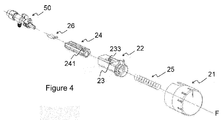
- Figure 4
- is the general exploded view showing the sub-components forming the subject matter control pushbutton.
- Figure 5
- is the perspective view showing the section where the tab, existing on the subject matter control pushbutton, is provided.
- Figure 6
- is the top view showing the section where the tab, existing on the subject matter control pushbutton, is provided.
- The present invention relates to a home appliance (1) having rotary control pushbutton (2) where the number of sub-components is reduced and the assembly of the pushbutton is facilitated and the assembly duration is shortened and production is facilitated. The control pushbutton (2) is connected to a control element (50) and it can be used in all home appliances. A cooking device having a control element (50) and a tap functioning by means of gas is illustrated in
Figure 1 . - In
Figure 2 , the general perspective view of the subject matter control pushbutton (2) is given. The rotary control pushbutton (2) comprises a control sleeve (21) having a cylindrical structure, a helical spring (25) placed into the gap formed by the cylindrical periphery of the control sleeve (21), an inner body (22) which is similar to a rectangular prism, and a guide element (24) axially guided to the gap provided in the inner body (22). As can be seen in the cross sectional view given inFigure 3 , there are channels (241) on the guide element (24). These channels (241) are formed for providing movement of a tab (23) positioned on the inner body (22). Moreover, there is a connection element (26) in the control pushbutton (2), and said connection element (26) is connected to the shafts of the elements like switch, thermostat, gas tap or electrical stove regulator, and said connection element (26) prevents unintentional and uncontrolled removal of the pushbutton. - The control pushbutton (2) switches to an operation position by exerting pressure with fingertip in the direction of the movement axis (F) through a push surface (211) provided on a control sleeve (21). Again in the same manner, the pushbutton switches to the stop position by exerting pressure in the direction of the center movement axis (F) through the same push surface (211) provided on said control sleeve (21). Thus, the releasing-retracting of the control pushbutton (2) is realized in the axial direction by means of the exerted pressure. The pushbutton can also be rotated around its own axis.
- In the present invention, the operation-stop positions of the pushbutton, in other words, the axial releasing-retracting actions of the pushbutton are provided with the help of a tab (23) moving inside the channels (241) provided on the guide element (24). In more details, by means of a pressure to be exerted through the push surface (211) of the pushbutton, the tab (23) advances inside the channels (241) having an indented form, and it is fixed to a channel section which has a form suitable for locking, and it provides the pushbutton to stay in this position. Again in the same manner, as a result of the exerted pressure, the tab (23) is released from this mentioned position, and by means of the axial back movement inside the channels (241), the pushbutton returns to its initial position.
- As can be seen in
Figure 4 , the control pushbutton (2) comprises a control sleeve (21), a helical spring (25), an inner body (22), a guide element (24) and a connection element (26). Again here, a tap operating with gas and having a control element (50) controlled by means of the control pushbutton (2) can be seen. The shaft of the tap operating with gas engages to a connection channel (242) provided on the guide element (24) and illustrated inFigure 3 , and it is connected with respect to the center movement axis (F). - As can be seen in
Figure 5 , the tab (23) moving in the channels (241) provided on the guide element (24) is positioned to an inner edge (222) provided in an opening (221) existing on the inner body (22). In the subject matter invention, the inner body (22) and said tab (23) are manufactured in a one-piece manner from the same plastic material by means of injection method. Again as seen inFigure 5 , there is a neck section (233) on the tab (23). The neck section (233) is positioned on the tab (23) in the region between the inner edge (222) and the tab end section (232). In the top view of the tab (23) given inFigure 6 , the tab (23) has a form which is similar to rectangular prism and "U"-like form is created in the regions where the neck section (233) is provided. The width (234) of said neck section is smaller than the tab width (231). Again, at least one of the corners provided on the tab (23) has a rounded corner (235). The rounded corner (235) is provided by forming curve at the corners of the tab (23) by means of breaking chamfer. -
- 1
- Home appliance
- 2
- Control pushbutton
- 21
- Control sleeve
- 211
- Push surface
- 22
- Inner body
- 221
- Opening
- 222
- Inner edge
- 23
- Tab
- 231
- Tab width
- 232
- Tab end section
- 233
- Neck section
- 234
- Neck section width
- 235
- Rounded corner
- 24
- Guide element
- 241
- Channels
- 242
- Connection channel
- 25
- Helical spring
- 26
- Connection element
- 50
- Control element
- F
- Center movement axis
Claims (6)
- A home appliance (1) having a rotary control pushbutton (2) connected to a control element (50) and comprising a control sleeve (21), an inner body (22) placed into the control sleeve (21), and a guide element (24) guided to the inner body (22) and having channels (241) thereon, characterized in that said control pushbutton (2) comprises a tab (23) which is one-piece with the inner body (22) and positioned to an inner edge (222) of an opening (221) formed on the inner body (22), said tab providing adjustment of the start and stop positions of the pushbutton by moving axially in the channels (241) provided on the guide element (24).
- A home appliance (1) according to Claim 1, wherein a neck section (233) is provided on the tab (23) in the region between the inner edge (222) and the tab end section (232).
- A home appliance (1) according to Claim 2, wherein the neck section (233) width (234) is smaller than the tab width (231).
- A home appliance (1) according to any one of the preceding claims, wherein at least one of the corners provided on the tab (23) is a rounded corner (235).
- A home appliance (1) according to any one of the preceding claims, wherein the tab (23) and the inner body (22) are made of the same plastic material.
- A home appliance (1) according to any one of the preceding claims, wherein the present invention is a cooking device with a control element (50) has a gas tap.
Applications Claiming Priority (1)
| Application Number | Priority Date | Filing Date | Title |
|---|---|---|---|
| TR201509506 | 2015-07-31 |
Publications (2)
| Publication Number | Publication Date |
|---|---|
| EP3125066A2 true EP3125066A2 (en) | 2017-02-01 |
| EP3125066A3 EP3125066A3 (en) | 2017-02-08 |
Family
ID=56296736
Family Applications (1)
| Application Number | Title | Priority Date | Filing Date |
|---|---|---|---|
| EP16177534.1A Withdrawn EP3125066A3 (en) | 2015-07-31 | 2016-07-01 | A cooking device having a control pushbutton |
Country Status (1)
| Country | Link |
|---|---|
| EP (1) | EP3125066A3 (en) |
Cited By (3)
| Publication number | Priority date | Publication date | Assignee | Title |
|---|---|---|---|---|
| JP2020521550A (en) * | 2017-05-30 | 2020-07-27 | ウェスト ファーマ サービシーズ イスラエル リミテッド | Vertical structure of printed circuit board |
| US11819666B2 (en) | 2017-05-30 | 2023-11-21 | West Pharma. Services IL, Ltd. | Modular drive train for wearable injector |
| US12357767B2 (en) | 2016-08-01 | 2025-07-15 | West Pharma. Services IL, Ltd. | Partial door closure prevention spring |
Citations (1)
| Publication number | Priority date | Publication date | Assignee | Title |
|---|---|---|---|---|
| US6410871B1 (en) | 1999-06-19 | 2002-06-25 | Mannesmann Vdo Ag | Retractable rotary knob for switch including latch mechanism |
Family Cites Families (6)
| Publication number | Priority date | Publication date | Assignee | Title |
|---|---|---|---|---|
| TR199600723A2 (en) * | 1996-09-12 | 1998-04-21 | Ar�El�K A.�. | Control button used in home appliances. |
| DE10306583A1 (en) * | 2003-02-17 | 2004-09-02 | BSH Bosch und Siemens Hausgeräte GmbH | A latching system for depressible items, such as cooker switch knobs, has a sliding part within a housing having deformable retaining bars engaging a heart shaped projection on the sliding part |
| EP1526422B1 (en) * | 2003-10-22 | 2007-02-14 | Lisi Automotive Rapid | Retractable rotating knob of a switch or positioning device, especially of a household appliance |
| TR200502678U (en) * | 2005-07-08 | 2005-09-21 | Ocak Kalip İmalat San.Ve Ti̇c.Ltd.Şti̇. | Innovation in the control knob used in cooking hobs |
| WO2008039159A1 (en) * | 2006-09-27 | 2008-04-03 | Ocak Kalip Makina Imalat Sanayi Ve Ticaret Limited Sirketi | Reinforced locker in control knob mechanisms |
| EP3063599B1 (en) * | 2013-11-01 | 2019-07-17 | Arçelik Anonim Sirketi | A household appliance comprising a knob |
-
2016
- 2016-07-01 EP EP16177534.1A patent/EP3125066A3/en not_active Withdrawn
Patent Citations (1)
| Publication number | Priority date | Publication date | Assignee | Title |
|---|---|---|---|---|
| US6410871B1 (en) | 1999-06-19 | 2002-06-25 | Mannesmann Vdo Ag | Retractable rotary knob for switch including latch mechanism |
Cited By (3)
| Publication number | Priority date | Publication date | Assignee | Title |
|---|---|---|---|---|
| US12357767B2 (en) | 2016-08-01 | 2025-07-15 | West Pharma. Services IL, Ltd. | Partial door closure prevention spring |
| JP2020521550A (en) * | 2017-05-30 | 2020-07-27 | ウェスト ファーマ サービシーズ イスラエル リミテッド | Vertical structure of printed circuit board |
| US11819666B2 (en) | 2017-05-30 | 2023-11-21 | West Pharma. Services IL, Ltd. | Modular drive train for wearable injector |
Also Published As
| Publication number | Publication date |
|---|---|
| EP3125066A3 (en) | 2017-02-08 |
Similar Documents
| Publication | Publication Date | Title |
|---|---|---|
| JP5982023B2 (en) | Rotation / push button control device | |
| EP3487469B1 (en) | Medicament container holder for a medicament delivery device and method of assemblying a medicament delivery device | |
| EP2485111B1 (en) | Improved retractable control device for domestic appliance | |
| EP3490645B1 (en) | Cap assembly for a medicament delivery device | |
| CN109475701B (en) | Medication Container Assembly for Medication Delivery Device | |
| US6972387B2 (en) | Padlockable push-button | |
| EP3087320B1 (en) | A cooking appliance which includes a gas tap equipped with a tactile feedback device | |
| EP3462092A1 (en) | A cooking device having a control knob | |
| EP3234974B1 (en) | Operator control device for a vehicle, in particular a passenger car | |
| DE102006036636A1 (en) | Locking device for e.g. motor vehicle rotary switch, has disc-shaped stop spring twistably mounted on housings, and adjusting knob torque-proofly connected with stop spring, where latch is provided at spring for fastening knob | |
| WO2018024386A1 (en) | Thermal switching device | |
| EP3125066A3 (en) | A cooking device having a control pushbutton | |
| EP2735795B1 (en) | Gas tap for a cooking appliance | |
| EP3348716A1 (en) | Support device for a shower head | |
| EP2469551B1 (en) | Cooking appliance having pop-out type control knob assembly | |
| EP3117850A1 (en) | Applicator with plunger having movable range restricted by resistance structure | |
| EP3323135B1 (en) | Lever actuator for controlling electrical devices | |
| KR101222707B1 (en) | a catheter for redirecting of guide wire and method redirecting using thereof | |
| EP3007193B1 (en) | A tap-changer for oil-filled electric transformers | |
| EP3282194B1 (en) | A control knob equipped with a gear box for controlling power level of a burner in a gas cooker | |
| EP2597376B1 (en) | A cooking device having a gas tap shaft | |
| CN112471906B (en) | Cooking device and cover assembly thereof | |
| KR0122763Y1 (en) | Knob structure for microwave oven control | |
| EP2650748A1 (en) | A home appliance comprising a control knob | |
| WO2013120634A1 (en) | Electrical pushbutton having a sealing bellows and a spring charging the sealing bellows, and method for the assembly thereof |
Legal Events
| Date | Code | Title | Description |
|---|---|---|---|
| PUAI | Public reference made under article 153(3) epc to a published international application that has entered the european phase |
Free format text: ORIGINAL CODE: 0009012 |
|
| PUAL | Search report despatched |
Free format text: ORIGINAL CODE: 0009013 |
|
| AK | Designated contracting states |
Kind code of ref document: A2 Designated state(s): AL AT BE BG CH CY CZ DE DK EE ES FI FR GB GR HR HU IE IS IT LI LT LU LV MC MK MT NL NO PL PT RO RS SE SI SK SM TR |
|
| AX | Request for extension of the european patent |
Extension state: BA ME |
|
| AK | Designated contracting states |
Kind code of ref document: A3 Designated state(s): AL AT BE BG CH CY CZ DE DK EE ES FI FR GB GR HR HU IE IS IT LI LT LU LV MC MK MT NL NO PL PT RO RS SE SI SK SM TR |
|
| AX | Request for extension of the european patent |
Extension state: BA ME |
|
| RIC1 | Information provided on ipc code assigned before grant |
Ipc: G05G 1/08 20060101AFI20170102BHEP |
|
| STAA | Information on the status of an ep patent application or granted ep patent |
Free format text: STATUS: THE APPLICATION IS DEEMED TO BE WITHDRAWN |
|
| 18D | Application deemed to be withdrawn |
Effective date: 20170809 |