EP3124800A1 - Clamp device with resilience - Google Patents
Clamp device with resilience Download PDFInfo
- Publication number
- EP3124800A1 EP3124800A1 EP15179413.8A EP15179413A EP3124800A1 EP 3124800 A1 EP3124800 A1 EP 3124800A1 EP 15179413 A EP15179413 A EP 15179413A EP 3124800 A1 EP3124800 A1 EP 3124800A1
- Authority
- EP
- European Patent Office
- Prior art keywords
- clamping plate
- connection rod
- clamping
- clamp device
- plate
- Prior art date
- Legal status (The legal status is an assumption and is not a legal conclusion. Google has not performed a legal analysis and makes no representation as to the accuracy of the status listed.)
- Granted
Links
- XEEYBQQBJWHFJM-UHFFFAOYSA-N Iron Chemical compound [Fe] XEEYBQQBJWHFJM-UHFFFAOYSA-N 0.000 claims description 10
- 229910000831 Steel Inorganic materials 0.000 claims description 5
- 229910052742 iron Inorganic materials 0.000 claims description 5
- 239000010959 steel Substances 0.000 claims description 5
- 238000003825 pressing Methods 0.000 claims description 2
- 239000003795 chemical substances by application Substances 0.000 description 2
- 238000000034 method Methods 0.000 description 2
- 239000011248 coating agent Substances 0.000 description 1
- 238000000576 coating method Methods 0.000 description 1
- 238000004519 manufacturing process Methods 0.000 description 1
- 239000002184 metal Substances 0.000 description 1
- 229910052751 metal Inorganic materials 0.000 description 1
- 238000012986 modification Methods 0.000 description 1
- 230000004048 modification Effects 0.000 description 1
- 239000000126 substance Substances 0.000 description 1
Images

Classifications
-
- B—PERFORMING OPERATIONS; TRANSPORTING
- B62—LAND VEHICLES FOR TRAVELLING OTHERWISE THAN ON RAILS
- B62K—CYCLES; CYCLE FRAMES; CYCLE STEERING DEVICES; RIDER-OPERATED TERMINAL CONTROLS SPECIALLY ADAPTED FOR CYCLES; CYCLE AXLE SUSPENSIONS; CYCLE SIDE-CARS, FORECARS, OR THE LIKE
- B62K19/00—Cycle frames
- B62K19/18—Joints between frame members
- B62K19/24—Screwed joints
-
- F—MECHANICAL ENGINEERING; LIGHTING; HEATING; WEAPONS; BLASTING
- F16—ENGINEERING ELEMENTS AND UNITS; GENERAL MEASURES FOR PRODUCING AND MAINTAINING EFFECTIVE FUNCTIONING OF MACHINES OR INSTALLATIONS; THERMAL INSULATION IN GENERAL
- F16B—DEVICES FOR FASTENING OR SECURING CONSTRUCTIONAL ELEMENTS OR MACHINE PARTS TOGETHER, e.g. NAILS, BOLTS, CIRCLIPS, CLAMPS, CLIPS OR WEDGES; JOINTS OR JOINTING
- F16B7/00—Connections of rods or tubes, e.g. of non-circular section, mutually, including resilient connections
- F16B7/18—Connections of rods or tubes, e.g. of non-circular section, mutually, including resilient connections using screw-thread elements
-
- B—PERFORMING OPERATIONS; TRANSPORTING
- B62—LAND VEHICLES FOR TRAVELLING OTHERWISE THAN ON RAILS
- B62K—CYCLES; CYCLE FRAMES; CYCLE STEERING DEVICES; RIDER-OPERATED TERMINAL CONTROLS SPECIALLY ADAPTED FOR CYCLES; CYCLE AXLE SUSPENSIONS; CYCLE SIDE-CARS, FORECARS, OR THE LIKE
- B62K2201/00—Springs used in cycle frames or parts thereof
- B62K2201/06—Leaf springs
-
- F—MECHANICAL ENGINEERING; LIGHTING; HEATING; WEAPONS; BLASTING
- F16—ENGINEERING ELEMENTS AND UNITS; GENERAL MEASURES FOR PRODUCING AND MAINTAINING EFFECTIVE FUNCTIONING OF MACHINES OR INSTALLATIONS; THERMAL INSULATION IN GENERAL
- F16B—DEVICES FOR FASTENING OR SECURING CONSTRUCTIONAL ELEMENTS OR MACHINE PARTS TOGETHER, e.g. NAILS, BOLTS, CIRCLIPS, CLAMPS, CLIPS OR WEDGES; JOINTS OR JOINTING
- F16B2/00—Friction-grip releasable fastenings
- F16B2/20—Clips, i.e. with gripping action effected solely by the inherent resistance to deformation of the material of the fastening
- F16B2/22—Clips, i.e. with gripping action effected solely by the inherent resistance to deformation of the material of the fastening of resilient material, e.g. rubbery material
- F16B2/24—Clips, i.e. with gripping action effected solely by the inherent resistance to deformation of the material of the fastening of resilient material, e.g. rubbery material of metal
- F16B2/241—Clips, i.e. with gripping action effected solely by the inherent resistance to deformation of the material of the fastening of resilient material, e.g. rubbery material of metal of sheet metal
- F16B2/245—Clips, i.e. with gripping action effected solely by the inherent resistance to deformation of the material of the fastening of resilient material, e.g. rubbery material of metal of sheet metal external, i.e. with contracting action
-
- F—MECHANICAL ENGINEERING; LIGHTING; HEATING; WEAPONS; BLASTING
- F16—ENGINEERING ELEMENTS AND UNITS; GENERAL MEASURES FOR PRODUCING AND MAINTAINING EFFECTIVE FUNCTIONING OF MACHINES OR INSTALLATIONS; THERMAL INSULATION IN GENERAL
- F16B—DEVICES FOR FASTENING OR SECURING CONSTRUCTIONAL ELEMENTS OR MACHINE PARTS TOGETHER, e.g. NAILS, BOLTS, CIRCLIPS, CLAMPS, CLIPS OR WEDGES; JOINTS OR JOINTING
- F16B37/00—Nuts or like thread-engaging members
- F16B37/02—Nuts or like thread-engaging members made of thin sheet material
-
- F—MECHANICAL ENGINEERING; LIGHTING; HEATING; WEAPONS; BLASTING
- F16—ENGINEERING ELEMENTS AND UNITS; GENERAL MEASURES FOR PRODUCING AND MAINTAINING EFFECTIVE FUNCTIONING OF MACHINES OR INSTALLATIONS; THERMAL INSULATION IN GENERAL
- F16B—DEVICES FOR FASTENING OR SECURING CONSTRUCTIONAL ELEMENTS OR MACHINE PARTS TOGETHER, e.g. NAILS, BOLTS, CIRCLIPS, CLAMPS, CLIPS OR WEDGES; JOINTS OR JOINTING
- F16B7/00—Connections of rods or tubes, e.g. of non-circular section, mutually, including resilient connections
- F16B7/22—Connections of rods or tubes, e.g. of non-circular section, mutually, including resilient connections using hooks or like elements
Definitions
- the present invention relates to leaf springs and more particularly to a clamp device with resilience for use with a stem of a folding bicycle.
- European Patent Application EP 2471701 A1 is directed to a folding device of a folding bicycle and discloses a connection device 40 thereof.
- the step of connecting a first bar shaft 41 to a guide slot 433 of a rod 42 also entails coating the connection device 40 with a locking agent for preventing the connection device 40 from loosening.
- connection device 40 of a bicycle gets loosened as a result of the vibration the bicycle in operation and repeated disassembly of the bicycle. Accordingly, the prior art still has room for improvement.
- connection device usually a slender bar
- the present invention provides a clamp device with resilience, for use in clamping a slender bar including a connection rod and a bar shaft, with the connection rod being a long polyhedron and including at least a polygonal vertex and at least a polygonal face.
- the clamp device with resilience comprises a clamping portion and a fixing portion.
- the clamping portion comprises: a first clamping plate; and a second clamping plate opposing the first clamping plate, wherein the second clamping plate and the first clamping plate together form a space for containing and clamping the connection rod.
- the fixing portion is connected to the clamping portion and adapted to receive the bar shaft.
- connection rod When the first clamping plate and the second clamping plate clamp the connection rod, a user rotates the connection rod to cause the first clamping plate and the second clamping plate to come into contact with the at least a polygonal vertex, such that the at least a polygonal vertex draws apart the first clamping plate and the second clamping plate, thereby causing the first clamping plate and the second clamping plate to move away from each other and allowing the connection rod to rotate by an angle.
- the first clamping plate and the second clamping plate are each a resilient plate.
- the resilient plate is a steel resilient plate or an iron resilient plate.
- the first clamping plate and the second clamping plate are parallel to each other.
- connection rod comprises a thread portion
- fixing portion comprises a hole penetrable by the thread portion
- the clamping portion further comprises a top plate for pressing the connection rod to fix the connection rod in place.
- the first clamping plate and the second clamping plate each further comprise convolution portions corresponding in position to each other.
- the convolution portions are serrated and have rounded corners.
- the fixing portion comprises a curved bent arm corresponding in shape to the bar shaft.
- FIG. 1 is a perspective view of a clamp device 1 with resilience according to the present invention.
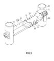
- FIG. 2 is a schematic view of operation of the clamp device 1 with resilience according to the present invention.
- the clamp device 1 with resilience and a slender bar 80 are adapted to be coupled together.
- the slender bar 80 comprises a connection rod 81 and a bar shaft 82.
- the connection rod 81 is a hex bolt and comprises six polygonal faces 812 and six polygonal vertices 811.
- the bar shaft 82 is a stud.
- the connection rod 81 and the bar shaft 82 are threaded and therefore can be meshed with each other.
- the clamp device 1 with resilience comprises a clamping portion 10 and a fixing portion 20.
- the clamping portion 10 is for containing and clamping the connection rod 81.
- the fixing portion 20 is for receiving and fixing the bar shaft 82 in place.
- the fixing portion 20 comprises a curved bent arm corresponding in shape to the bar shaft 82.
- the clamping portion 10 comprises a first clamping plate 11 and a second clamping plate 12.
- the first and second clamping plates 11, 12 are made of steel or iron and opposite each other to form a space there between for containing and clamping the connection rod 81.
- the connection rod 81 draws apart the first clamping plate 11 and the second clamping plate 12 which are made of steel or iron and therefore exhibit resilience such that the connection rod 81 can smoothly enter the containing space formed by the first clamping plate 11 and the second clamping plate 12.
- the first clamping plate 11 and the second clamping plate 12 come into contact with the polygonal faces 812 and clamp the connection rod 81 under a clamping force exerted by the first clamping plate 11 and the second clamping plate 12.
- the first clamping plate 11 and the second clamping plate 12 are each a resilient plate made of steel, iron, any other metal with appropriate elasticity, or any other substance with appropriate elasticity.
- the first clamping plate 11 and the second clamping plate 12 are parallel to each other.
- the connection rod 81 which is a hex bolt, has three pairs of parallel polygonal faces 812. Therefore, when the connection rod 81 is clamped by the clamp device 1 with resilience according to the present invention, one of the three pairs of polygonal faces 812 of the connection rod 81 come into contact with the first clamping plate 11 and the second clamping plate 12.
- connection rod 81 When the first clamping plate 11 and the second clamping plate 12 clamp the connection rod 81, a user rotates the connection rod 81 to cause a curved bent arm of the fixing portion 20 to receive and fix the bar shaft 82 in place to thereby keep the bar shaft 82 still but allow the connection rod 81 to rotate.
- connection rod 81 causes the first clamping plate 11 and the second clamping plate 12 to come into contact with the polygonal vertices 811 of the connection rod 81, and in consequence the first clamping plate 11 and the second clamping plate 12 are drawn apart from each other because of the relatively long distance between the polygonal vertices 811 (which join the diameter of the external circle of the hex bolt), thereby causing the first clamping plate 11 and the second clamping plate 12 to move away from each other. Therefore, the connection rod 81 is rotated by an angle on each instance. The rotation of the connection rod 81 by the angle causes the first clamping plate 11 and the second clamping plate 12 to come into contact with the next pair of polygonal faces 812, and in consequence the clamp device 1 with resilience restores its initial clamping state.
- connection rod 81 must be rotated by a fixed angle.
- the connection rod 81 in this embodiment is the hex bolt
- the connection rod 81 is rotated by 60 degrees on each instance.
- the connection rod 81 is not restricted to a hex bolt; hence, the connection rod 81 can work, provided that it has even-numbered pairs of polygonal faces.
- the connection rod 81 can be a square bolt (rotated by 90 degrees on each instance), an octagonal bolt (rotated by 45 degrees on each instance), etc.
- the fixing portion 20 further comprises a hole 21 penetrable by a thread portion of the connection rod 81 to thereby lengthen the journey of the connection between the connection rod 81 and the bar shaft 82 of the slender bar 80.
- the fixing portion 20 dispenses with the hole 21 and therefore reduces the amount of adjustment of the journey of the connection rod 81.
- two polygonal vertices at the bottom ends of the first clamping plate 11 and the second clamping plate 12 on one side of the clamping portion 10 can be manufactured to form rounded angles rather than right angles, so as to meet a process need.
- the clamping portion 10 further comprises a top plate 14 for abutting against and exerting a force upon the connection rod 81 to fix the connection rod 81 in place.
- the top plate 14 will be dispensable such that the connection rod 81 can be fixed in place by allowing the one side of the clamping portion 10 to come into contact with a corresponding one of the polygonal faces 812 of the connection rod 81.
- the first clamping plate 11 and the second clamping plate 12 each have a plurality of convolution portions 13.
- the convolution portions 13 are serrated and have rounded corners to thereby conform with the rise and fall of the polygonal vertices 811 protruding outward as a result of the rotation of the connection rod 81. That said, the present invention is not limited to the aforesaid shape of the convolution portions 13, as the convolution portions 13 can also take on any other appropriate shapes; for example, the convolution portions 13 can be triangularly serrated or squarely serrated.
Abstract
Description
- The present invention relates to leaf springs and more particularly to a clamp device with resilience for use with a stem of a folding bicycle.
- Due to their portability, folding bicycles are in wide use. Regarding the structure of a conventional folding bicycle, a stem is fixed in place or disconnected by a connection device. For example, European Patent Application
EP 2471701 A1 is directed to a folding device of a folding bicycle and discloses a connection device 40 thereof. During a folding bicycle manufacturing process, the step of connecting a first bar shaft 41 to a guide slot 433 of a rod 42 also entails coating the connection device 40 with a locking agent for preventing the connection device 40 from loosening. - However, in practice, the service life of the locking agent is never unlimited, because the connection device 40 of a bicycle gets loosened as a result of the vibration the bicycle in operation and repeated disassembly of the bicycle. Accordingly, the prior art still has room for improvement.
- It is an objective of the present invention to provide a clamp device with resilience to solve the problem with the vibration and disconnection of a connection device (usually a slender bar) disposed in a folding structure of a stem of a folding bicycle.
- In order to achieve the above and other objectives, the present invention provides a clamp device with resilience, for use in clamping a slender bar including a connection rod and a bar shaft, with the connection rod being a long polyhedron and including at least a polygonal vertex and at least a polygonal face. The clamp device with resilience comprises a clamping portion and a fixing portion. The clamping portion comprises: a first clamping plate; and a second clamping plate opposing the first clamping plate, wherein the second clamping plate and the first clamping plate together form a space for containing and clamping the connection rod. The fixing portion is connected to the clamping portion and adapted to receive the bar shaft. When the first clamping plate and the second clamping plate clamp the connection rod, a user rotates the connection rod to cause the first clamping plate and the second clamping plate to come into contact with the at least a polygonal vertex, such that the at least a polygonal vertex draws apart the first clamping plate and the second clamping plate, thereby causing the first clamping plate and the second clamping plate to move away from each other and allowing the connection rod to rotate by an angle.
- According to an embodiment of the present invention, the first clamping plate and the second clamping plate are each a resilient plate.
- According to an embodiment of the present invention, the resilient plate is a steel resilient plate or an iron resilient plate.
- According to an embodiment of the present invention, the first clamping plate and the second clamping plate are parallel to each other.
- According to an embodiment of the present invention, the connection rod comprises a thread portion, and the fixing portion comprises a hole penetrable by the thread portion.
- According to an embodiment of the present invention, the clamping portion further comprises a top plate for pressing the connection rod to fix the connection rod in place.
- According to an embodiment of the present invention, the first clamping plate and the second clamping plate each further comprise convolution portions corresponding in position to each other.
- According to an embodiment of the present invention, the convolution portions are serrated and have rounded corners.
- According to an embodiment of the present invention, the fixing portion comprises a curved bent arm corresponding in shape to the bar shaft.
-
-
FIG. 1 is a perspective view of a clamp device with resilience according to the present invention; and -
FIG. 2 is a schematic view of operation of the clamp device with resilience according to the present invention. - The present invention is hereunder illustrated with preferred embodiments.
-
FIG. 1 is a perspective view of aclamp device 1 with resilience according to the present invention.FIG. 2 is a schematic view of operation of theclamp device 1 with resilience according to the present invention. Referring toFIG. 2 , theclamp device 1 with resilience and a slender bar 80 are adapted to be coupled together. The slender bar 80 comprises aconnection rod 81 and abar shaft 82. In an embodiment of the present invention, theconnection rod 81 is a hex bolt and comprises sixpolygonal faces 812 and sixpolygonal vertices 811. Thebar shaft 82 is a stud. Theconnection rod 81 and thebar shaft 82 are threaded and therefore can be meshed with each other. - The
clamp device 1 with resilience comprises a clampingportion 10 and afixing portion 20. Theclamping portion 10 is for containing and clamping theconnection rod 81. Thefixing portion 20 is for receiving and fixing thebar shaft 82 in place. In an embodiment of the present invention, thefixing portion 20 comprises a curved bent arm corresponding in shape to thebar shaft 82. Theclamping portion 10 comprises afirst clamping plate 11 and asecond clamping plate 12. The first andsecond clamping plates connection rod 81. In an embodiment of the present invention, when theclamp device 1 with resilience and the slender bar 80 are coupled together, theconnection rod 81 draws apart thefirst clamping plate 11 and thesecond clamping plate 12 which are made of steel or iron and therefore exhibit resilience such that theconnection rod 81 can smoothly enter the containing space formed by thefirst clamping plate 11 and thesecond clamping plate 12. After theconnection rod 81 has entered the containing space, thefirst clamping plate 11 and thesecond clamping plate 12 come into contact with thepolygonal faces 812 and clamp theconnection rod 81 under a clamping force exerted by thefirst clamping plate 11 and thesecond clamping plate 12. In an embodiment of the present invention, thefirst clamping plate 11 and thesecond clamping plate 12 are each a resilient plate made of steel, iron, any other metal with appropriate elasticity, or any other substance with appropriate elasticity. - In an embodiment of the present invention, the
first clamping plate 11 and thesecond clamping plate 12 are parallel to each other. Theconnection rod 81, which is a hex bolt, has three pairs of parallelpolygonal faces 812. Therefore, when theconnection rod 81 is clamped by theclamp device 1 with resilience according to the present invention, one of the three pairs ofpolygonal faces 812 of theconnection rod 81 come into contact with thefirst clamping plate 11 and thesecond clamping plate 12. - When the
first clamping plate 11 and thesecond clamping plate 12 clamp theconnection rod 81, a user rotates theconnection rod 81 to cause a curved bent arm of thefixing portion 20 to receive and fix thebar shaft 82 in place to thereby keep thebar shaft 82 still but allow theconnection rod 81 to rotate. The rotation of theconnection rod 81 causes thefirst clamping plate 11 and thesecond clamping plate 12 to come into contact with thepolygonal vertices 811 of theconnection rod 81, and in consequence thefirst clamping plate 11 and thesecond clamping plate 12 are drawn apart from each other because of the relatively long distance between the polygonal vertices 811 (which join the diameter of the external circle of the hex bolt), thereby causing thefirst clamping plate 11 and thesecond clamping plate 12 to move away from each other. Therefore, theconnection rod 81 is rotated by an angle on each instance. The rotation of theconnection rod 81 by the angle causes thefirst clamping plate 11 and thesecond clamping plate 12 to come into contact with the next pair ofpolygonal faces 812, and in consequence theclamp device 1 with resilience restores its initial clamping state. - Due to the aforesaid structure, the
connection rod 81 must be rotated by a fixed angle. For example, when theconnection rod 81 in this embodiment is the hex bolt, theconnection rod 81 is rotated by 60 degrees on each instance. According to the present invention, theconnection rod 81 is not restricted to a hex bolt; hence, theconnection rod 81 can work, provided that it has even-numbered pairs of polygonal faces. For example, theconnection rod 81 can be a square bolt (rotated by 90 degrees on each instance), an octagonal bolt (rotated by 45 degrees on each instance), etc. - In an embodiment of the present invention, the
fixing portion 20 further comprises ahole 21 penetrable by a thread portion of theconnection rod 81 to thereby lengthen the journey of the connection between theconnection rod 81 and thebar shaft 82 of the slender bar 80. In another embodiment of the present invention, thefixing portion 20 dispenses with thehole 21 and therefore reduces the amount of adjustment of the journey of theconnection rod 81. - In an embodiment of the present invention, two polygonal vertices (at the bottom ends of the
first clamping plate 11 and the second clamping plate 12) on one side of theclamping portion 10 can be manufactured to form rounded angles rather than right angles, so as to meet a process need. Theclamping portion 10 further comprises atop plate 14 for abutting against and exerting a force upon theconnection rod 81 to fix theconnection rod 81 in place. If, to meet a process need, two polygonal vertices on one side of theclamping portion 10 are right angles, thetop plate 14 will be dispensable such that theconnection rod 81 can be fixed in place by allowing the one side of theclamping portion 10 to come into contact with a corresponding one of thepolygonal faces 812 of theconnection rod 81. - In an embodiment of the present invention, the
first clamping plate 11 and thesecond clamping plate 12 each have a plurality ofconvolution portions 13. Theconvolution portions 13 are serrated and have rounded corners to thereby conform with the rise and fall of thepolygonal vertices 811 protruding outward as a result of the rotation of theconnection rod 81. That said, the present invention is not limited to the aforesaid shape of theconvolution portions 13, as theconvolution portions 13 can also take on any other appropriate shapes; for example, theconvolution portions 13 can be triangularly serrated or squarely serrated. - Although the present invention is disclosed above by embodiments, the embodiments are not restrictive of the present invention. Any persons skilled in the art can make some changes and modifications to the embodiments without departing from the spirit and scope of the present invention. Accordingly, the legal protection for the present invention should be defined by the appended claims.
Claims (9)
- A clamp device (1) with resilience, for use in clamping a slender bar (80) including a connection rod (81) and a bar shaft (82), with the connection rod (81) being a long polyhedron and including at least a polygonal vertex (811) and at least a polygonal face (812), the clamp device (1) comprising:a clamping portion (10), comprising:a first clamping plate (11); anda second clamping plate (12) opposing the first clamping plate (11), wherein the second clamping plate (12) and the first clamping plate (11) together form a space for containing andclamping the connection rod (81); anda fixing portion (20) connected to the clamping portion (10) and adapted to receive the bar shaft (82), wherein, when the first clamping plate (11) and the second clamping plate (12) clamp the connection rod (81), a user rotates the connection rod (81) to cause the first clamping plate (11) and the second clamping plate (12) to come into contact with the at least a polygonal vertex (811), such that the at least a polygonal vertex (811) draws apart the first clamping plate (11) and the second clamping plate (12), thereby causing the first clamping plate (11) and the second clamping plate (12) to move away from each other and allowing the connection rod (81) to rotate by an angle.
- The clamp device according to claim 1, wherein the first clamping plate (11) and the second clamping plate (12) are each a resilient plate.
- The clamp device according to claim 2, wherein the resilient plate is one of a steel resilient plate and an iron resilient plate.
- The clamp device according to any of the preceding claims, wherein the first clamping plate (11) and the second clamping plate (12) are parallel to each other.
- The clamp device according to any of the preceding claims, wherein the connection rod (81) comprises a thread portion, and the fixing portion (20) comprises a hole (21) penetrable by the thread portion.
- The clamp device according to any of the preceding claims, wherein the clamping portion (10) further comprises a top plate (14) for pressing the connection rod (81) to fix the connection rod (81) in place.
- The clamp device according to any of the preceding claims, wherein the first clamping plate (11) and the second clamping plate (12) each further comprise convolution portions (13) corresponding in position to each other.
- The clamp device according to claim 7, wherein the convolution portions (13) are serrated and have rounded corners.
- The clamp device according to any of the preceding claims, wherein the fixing portion (20) comprises a curved bent arm corresponding in shape to the bar shaft (82).
Priority Applications (2)
| Application Number | Priority Date | Filing Date | Title |
|---|---|---|---|
| EP15179413.8A EP3124800B1 (en) | 2015-07-31 | 2015-07-31 | Clamp device with resilience |
| DK15179413.8T DK3124800T3 (en) | 2015-07-31 | 2015-07-31 | SPRING DEVICE WITH SPRING |
Applications Claiming Priority (1)
| Application Number | Priority Date | Filing Date | Title |
|---|---|---|---|
| EP15179413.8A EP3124800B1 (en) | 2015-07-31 | 2015-07-31 | Clamp device with resilience |
Publications (2)
| Publication Number | Publication Date |
|---|---|
| EP3124800A1 true EP3124800A1 (en) | 2017-02-01 |
| EP3124800B1 EP3124800B1 (en) | 2019-05-15 |
Family
ID=53938087
Family Applications (1)
| Application Number | Title | Priority Date | Filing Date |
|---|---|---|---|
| EP15179413.8A Active EP3124800B1 (en) | 2015-07-31 | 2015-07-31 | Clamp device with resilience |
Country Status (2)
| Country | Link |
|---|---|
| EP (1) | EP3124800B1 (en) |
| DK (1) | DK3124800T3 (en) |
Citations (9)
| Publication number | Priority date | Publication date | Assignee | Title |
|---|---|---|---|---|
| US491036A (en) * | 1893-01-31 | Harrow | ||
| US1473177A (en) * | 1923-11-06 | Combination bolt and nut retainer | ||
| US3536281A (en) * | 1968-01-04 | 1970-10-27 | Illinois Tool Works | Bracket structure |
| US3827815A (en) * | 1971-07-12 | 1974-08-06 | Firth Cleveland Fastenings Ltd | Spring clips |
| US4476673A (en) * | 1983-03-11 | 1984-10-16 | Brown Ronald T | Shackle pin locking construction |
| GB2227053A (en) * | 1989-01-12 | 1990-07-18 | Melvyn Wilde | A clamp for elongate members |
| WO2009054345A1 (en) * | 2007-10-26 | 2009-04-30 | Daifuku Co., Ltd. | Structure for fixing member to rod-like member |
| EP2471701A1 (en) | 2010-12-31 | 2012-07-04 | Mobility Holdings, Limited | Hinge for a folding bicycle |
| JP2014152916A (en) * | 2013-02-13 | 2014-08-25 | Daiwa House Industry Co Ltd | Fixation clip |
-
2015
- 2015-07-31 DK DK15179413.8T patent/DK3124800T3/en active
- 2015-07-31 EP EP15179413.8A patent/EP3124800B1/en active Active
Patent Citations (9)
| Publication number | Priority date | Publication date | Assignee | Title |
|---|---|---|---|---|
| US491036A (en) * | 1893-01-31 | Harrow | ||
| US1473177A (en) * | 1923-11-06 | Combination bolt and nut retainer | ||
| US3536281A (en) * | 1968-01-04 | 1970-10-27 | Illinois Tool Works | Bracket structure |
| US3827815A (en) * | 1971-07-12 | 1974-08-06 | Firth Cleveland Fastenings Ltd | Spring clips |
| US4476673A (en) * | 1983-03-11 | 1984-10-16 | Brown Ronald T | Shackle pin locking construction |
| GB2227053A (en) * | 1989-01-12 | 1990-07-18 | Melvyn Wilde | A clamp for elongate members |
| WO2009054345A1 (en) * | 2007-10-26 | 2009-04-30 | Daifuku Co., Ltd. | Structure for fixing member to rod-like member |
| EP2471701A1 (en) | 2010-12-31 | 2012-07-04 | Mobility Holdings, Limited | Hinge for a folding bicycle |
| JP2014152916A (en) * | 2013-02-13 | 2014-08-25 | Daiwa House Industry Co Ltd | Fixation clip |
Also Published As
| Publication number | Publication date |
|---|---|
| EP3124800B1 (en) | 2019-05-15 |
| DK3124800T3 (en) | 2019-08-19 |
Similar Documents
| Publication | Publication Date | Title |
|---|---|---|
| JP5291693B2 (en) | Panel material self-supporting fixture | |
| US9163390B2 (en) | Supporting framework having connection nodes | |
| US10151336B2 (en) | Clamp device with resilience | |
| EP3124800B1 (en) | Clamp device with resilience | |
| JP2019095072A (en) | Cross connector | |
| US9212479B1 (en) | Supporting framework having connection nodes | |
| EP2873873B1 (en) | Folded beam clamp | |
| JP6263594B2 (en) | Cross connector | |
| CN104066545B (en) | Leading truck fastening | |
| KR102068607B1 (en) | Clamp for a scaffold | |
| JP6026497B2 (en) | Cross connector | |
| CN107703594A (en) | A kind of fixture for different-diameter communications optical cable | |
| JP2017172808A (en) | Cross connector | |
| CN208592772U (en) | Pipe tongs wrench | |
| CN207485784U (en) | A kind of mechanical fastening device | |
| KR101531333B1 (en) | Apparatus for prevention falling down ship block | |
| CN209793576U (en) | T-shaped wrench | |
| CN204141162U (en) | Fixed mechanism and use the The Cloud Terrace of this fixed mechanism | |
| JP2014134011A (en) | Brace fixture | |
| CN109967587A (en) | A kind of clamping device and stretch former | |
| CN216383335U (en) | Rotary swing arm seat mechanism capable of randomly adjusting rotary initial angle and resistance | |
| CN212249214U (en) | Fastener for construction | |
| CN211304309U (en) | Simple bending device for alloy part | |
| CN210470053U (en) | Electronic device mount pad convenient to installation | |
| US11433527B2 (en) | Adjustable cabinet assembly apparatus |
Legal Events
| Date | Code | Title | Description |
|---|---|---|---|
| PUAI | Public reference made under article 153(3) epc to a published international application that has entered the european phase |
Free format text: ORIGINAL CODE: 0009012 |
|
| STAA | Information on the status of an ep patent application or granted ep patent |
Free format text: STATUS: THE APPLICATION HAS BEEN PUBLISHED |
|
| AK | Designated contracting states |
Kind code of ref document: A1 Designated state(s): AL AT BE BG CH CY CZ DE DK EE ES FI FR GB GR HR HU IE IS IT LI LT LU LV MC MK MT NL NO PL PT RO RS SE SI SK SM TR |
|
| AX | Request for extension of the european patent |
Extension state: BA ME |
|
| STAA | Information on the status of an ep patent application or granted ep patent |
Free format text: STATUS: REQUEST FOR EXAMINATION WAS MADE |
|
| 17P | Request for examination filed |
Effective date: 20170728 |
|
| RBV | Designated contracting states (corrected) |
Designated state(s): AL AT BE BG CH CY CZ DE DK EE ES FI FR GB GR HR HU IE IS IT LI LT LU LV MC MK MT NL NO PL PT RO RS SE SI SK SM TR |
|
| GRAP | Despatch of communication of intention to grant a patent |
Free format text: ORIGINAL CODE: EPIDOSNIGR1 |
|
| STAA | Information on the status of an ep patent application or granted ep patent |
Free format text: STATUS: GRANT OF PATENT IS INTENDED |
|
| INTG | Intention to grant announced |
Effective date: 20181204 |
|
| GRAS | Grant fee paid |
Free format text: ORIGINAL CODE: EPIDOSNIGR3 |
|
| GRAA | (expected) grant |
Free format text: ORIGINAL CODE: 0009210 |
|
| STAA | Information on the status of an ep patent application or granted ep patent |
Free format text: STATUS: THE PATENT HAS BEEN GRANTED |
|
| AK | Designated contracting states |
Kind code of ref document: B1 Designated state(s): AL AT BE BG CH CY CZ DE DK EE ES FI FR GB GR HR HU IE IS IT LI LT LU LV MC MK MT NL NO PL PT RO RS SE SI SK SM TR |
|
| REG | Reference to a national code |
Ref country code: CH Ref legal event code: EP |
|
| REG | Reference to a national code |
Ref country code: DE Ref legal event code: R096 Ref document number: 602015030241 Country of ref document: DE |
|
| REG | Reference to a national code |
Ref country code: IE Ref legal event code: FG4D |
|
| REG | Reference to a national code |
Ref country code: NL Ref legal event code: FP |
|
| REG | Reference to a national code |
Ref country code: DK Ref legal event code: T3 Effective date: 20190816 |
|
| REG | Reference to a national code |
Ref country code: SE Ref legal event code: TRGR |
|
| REG | Reference to a national code |
Ref country code: LT Ref legal event code: MG4D |
|
| PG25 | Lapsed in a contracting state [announced via postgrant information from national office to epo] |
Ref country code: NO Free format text: LAPSE BECAUSE OF FAILURE TO SUBMIT A TRANSLATION OF THE DESCRIPTION OR TO PAY THE FEE WITHIN THE PRESCRIBED TIME-LIMIT Effective date: 20190815 Ref country code: FI Free format text: LAPSE BECAUSE OF FAILURE TO SUBMIT A TRANSLATION OF THE DESCRIPTION OR TO PAY THE FEE WITHIN THE PRESCRIBED TIME-LIMIT Effective date: 20190515 Ref country code: LT Free format text: LAPSE BECAUSE OF FAILURE TO SUBMIT A TRANSLATION OF THE DESCRIPTION OR TO PAY THE FEE WITHIN THE PRESCRIBED TIME-LIMIT Effective date: 20190515 Ref country code: PT Free format text: LAPSE BECAUSE OF FAILURE TO SUBMIT A TRANSLATION OF THE DESCRIPTION OR TO PAY THE FEE WITHIN THE PRESCRIBED TIME-LIMIT Effective date: 20190915 Ref country code: AL Free format text: LAPSE BECAUSE OF FAILURE TO SUBMIT A TRANSLATION OF THE DESCRIPTION OR TO PAY THE FEE WITHIN THE PRESCRIBED TIME-LIMIT Effective date: 20190515 Ref country code: ES Free format text: LAPSE BECAUSE OF FAILURE TO SUBMIT A TRANSLATION OF THE DESCRIPTION OR TO PAY THE FEE WITHIN THE PRESCRIBED TIME-LIMIT Effective date: 20190515 Ref country code: HR Free format text: LAPSE BECAUSE OF FAILURE TO SUBMIT A TRANSLATION OF THE DESCRIPTION OR TO PAY THE FEE WITHIN THE PRESCRIBED TIME-LIMIT Effective date: 20190515 |
|
| PGFP | Annual fee paid to national office [announced via postgrant information from national office to epo] |
Ref country code: DK Payment date: 20190731 Year of fee payment: 5 |
|
| PG25 | Lapsed in a contracting state [announced via postgrant information from national office to epo] |
Ref country code: GR Free format text: LAPSE BECAUSE OF FAILURE TO SUBMIT A TRANSLATION OF THE DESCRIPTION OR TO PAY THE FEE WITHIN THE PRESCRIBED TIME-LIMIT Effective date: 20190816 Ref country code: LV Free format text: LAPSE BECAUSE OF FAILURE TO SUBMIT A TRANSLATION OF THE DESCRIPTION OR TO PAY THE FEE WITHIN THE PRESCRIBED TIME-LIMIT Effective date: 20190515 Ref country code: BG Free format text: LAPSE BECAUSE OF FAILURE TO SUBMIT A TRANSLATION OF THE DESCRIPTION OR TO PAY THE FEE WITHIN THE PRESCRIBED TIME-LIMIT Effective date: 20190815 Ref country code: RS Free format text: LAPSE BECAUSE OF FAILURE TO SUBMIT A TRANSLATION OF THE DESCRIPTION OR TO PAY THE FEE WITHIN THE PRESCRIBED TIME-LIMIT Effective date: 20190515 |
|
| REG | Reference to a national code |
Ref country code: AT Ref legal event code: MK05 Ref document number: 1133773 Country of ref document: AT Kind code of ref document: T Effective date: 20190515 |
|
| PG25 | Lapsed in a contracting state [announced via postgrant information from national office to epo] |
Ref country code: RO Free format text: LAPSE BECAUSE OF FAILURE TO SUBMIT A TRANSLATION OF THE DESCRIPTION OR TO PAY THE FEE WITHIN THE PRESCRIBED TIME-LIMIT Effective date: 20190515 Ref country code: SK Free format text: LAPSE BECAUSE OF FAILURE TO SUBMIT A TRANSLATION OF THE DESCRIPTION OR TO PAY THE FEE WITHIN THE PRESCRIBED TIME-LIMIT Effective date: 20190515 Ref country code: CZ Free format text: LAPSE BECAUSE OF FAILURE TO SUBMIT A TRANSLATION OF THE DESCRIPTION OR TO PAY THE FEE WITHIN THE PRESCRIBED TIME-LIMIT Effective date: 20190515 Ref country code: AT Free format text: LAPSE BECAUSE OF FAILURE TO SUBMIT A TRANSLATION OF THE DESCRIPTION OR TO PAY THE FEE WITHIN THE PRESCRIBED TIME-LIMIT Effective date: 20190515 Ref country code: EE Free format text: LAPSE BECAUSE OF FAILURE TO SUBMIT A TRANSLATION OF THE DESCRIPTION OR TO PAY THE FEE WITHIN THE PRESCRIBED TIME-LIMIT Effective date: 20190515 |
|
| PGFP | Annual fee paid to national office [announced via postgrant information from national office to epo] |
Ref country code: SE Payment date: 20190722 Year of fee payment: 5 |
|
| REG | Reference to a national code |
Ref country code: DE Ref legal event code: R097 Ref document number: 602015030241 Country of ref document: DE |
|
| PG25 | Lapsed in a contracting state [announced via postgrant information from national office to epo] |
Ref country code: IT Free format text: LAPSE BECAUSE OF FAILURE TO SUBMIT A TRANSLATION OF THE DESCRIPTION OR TO PAY THE FEE WITHIN THE PRESCRIBED TIME-LIMIT Effective date: 20190515 Ref country code: SM Free format text: LAPSE BECAUSE OF FAILURE TO SUBMIT A TRANSLATION OF THE DESCRIPTION OR TO PAY THE FEE WITHIN THE PRESCRIBED TIME-LIMIT Effective date: 20190515 Ref country code: MC Free format text: LAPSE BECAUSE OF FAILURE TO SUBMIT A TRANSLATION OF THE DESCRIPTION OR TO PAY THE FEE WITHIN THE PRESCRIBED TIME-LIMIT Effective date: 20190515 |
|
| REG | Reference to a national code |
Ref country code: CH Ref legal event code: PL |
|
| PLBE | No opposition filed within time limit |
Free format text: ORIGINAL CODE: 0009261 |
|
| STAA | Information on the status of an ep patent application or granted ep patent |
Free format text: STATUS: NO OPPOSITION FILED WITHIN TIME LIMIT |
|
| PG25 | Lapsed in a contracting state [announced via postgrant information from national office to epo] |
Ref country code: TR Free format text: LAPSE BECAUSE OF FAILURE TO SUBMIT A TRANSLATION OF THE DESCRIPTION OR TO PAY THE FEE WITHIN THE PRESCRIBED TIME-LIMIT Effective date: 20190515 |
|
| 26N | No opposition filed |
Effective date: 20200218 |
|
| PG25 | Lapsed in a contracting state [announced via postgrant information from national office to epo] |
Ref country code: PL Free format text: LAPSE BECAUSE OF FAILURE TO SUBMIT A TRANSLATION OF THE DESCRIPTION OR TO PAY THE FEE WITHIN THE PRESCRIBED TIME-LIMIT Effective date: 20190515 |
|
| PG25 | Lapsed in a contracting state [announced via postgrant information from national office to epo] |
Ref country code: CH Free format text: LAPSE BECAUSE OF NON-PAYMENT OF DUE FEES Effective date: 20190731 Ref country code: LI Free format text: LAPSE BECAUSE OF NON-PAYMENT OF DUE FEES Effective date: 20190731 Ref country code: SI Free format text: LAPSE BECAUSE OF FAILURE TO SUBMIT A TRANSLATION OF THE DESCRIPTION OR TO PAY THE FEE WITHIN THE PRESCRIBED TIME-LIMIT Effective date: 20190515 Ref country code: LU Free format text: LAPSE BECAUSE OF NON-PAYMENT OF DUE FEES Effective date: 20190731 |
|
| PG25 | Lapsed in a contracting state [announced via postgrant information from national office to epo] |
Ref country code: IE Free format text: LAPSE BECAUSE OF NON-PAYMENT OF DUE FEES Effective date: 20190731 |
|
| REG | Reference to a national code |
Ref country code: DK Ref legal event code: EBP Effective date: 20200731 |
|
| REG | Reference to a national code |
Ref country code: SE Ref legal event code: EUG |
|
| PG25 | Lapsed in a contracting state [announced via postgrant information from national office to epo] |
Ref country code: CY Free format text: LAPSE BECAUSE OF FAILURE TO SUBMIT A TRANSLATION OF THE DESCRIPTION OR TO PAY THE FEE WITHIN THE PRESCRIBED TIME-LIMIT Effective date: 20190515 Ref country code: SE Free format text: LAPSE BECAUSE OF NON-PAYMENT OF DUE FEES Effective date: 20200801 |
|
| PG25 | Lapsed in a contracting state [announced via postgrant information from national office to epo] |
Ref country code: IS Free format text: LAPSE BECAUSE OF FAILURE TO SUBMIT A TRANSLATION OF THE DESCRIPTION OR TO PAY THE FEE WITHIN THE PRESCRIBED TIME-LIMIT Effective date: 20190915 |
|
| PG25 | Lapsed in a contracting state [announced via postgrant information from national office to epo] |
Ref country code: MT Free format text: LAPSE BECAUSE OF FAILURE TO SUBMIT A TRANSLATION OF THE DESCRIPTION OR TO PAY THE FEE WITHIN THE PRESCRIBED TIME-LIMIT Effective date: 20190515 Ref country code: HU Free format text: LAPSE BECAUSE OF FAILURE TO SUBMIT A TRANSLATION OF THE DESCRIPTION OR TO PAY THE FEE WITHIN THE PRESCRIBED TIME-LIMIT; INVALID AB INITIO Effective date: 20150731 |
|
| PG25 | Lapsed in a contracting state [announced via postgrant information from national office to epo] |
Ref country code: DK Free format text: LAPSE BECAUSE OF NON-PAYMENT OF DUE FEES Effective date: 20200731 |
|
| PG25 | Lapsed in a contracting state [announced via postgrant information from national office to epo] |
Ref country code: MK Free format text: LAPSE BECAUSE OF FAILURE TO SUBMIT A TRANSLATION OF THE DESCRIPTION OR TO PAY THE FEE WITHIN THE PRESCRIBED TIME-LIMIT Effective date: 20190515 |
|
| PGFP | Annual fee paid to national office [announced via postgrant information from national office to epo] |
Ref country code: NL Payment date: 20230726 Year of fee payment: 9 |
|
| PGFP | Annual fee paid to national office [announced via postgrant information from national office to epo] |
Ref country code: GB Payment date: 20230726 Year of fee payment: 9 |
|
| PGFP | Annual fee paid to national office [announced via postgrant information from national office to epo] |
Ref country code: FR Payment date: 20230726 Year of fee payment: 9 Ref country code: DE Payment date: 20230726 Year of fee payment: 9 Ref country code: BE Payment date: 20230726 Year of fee payment: 9 |