EP3124705A1 - Formers - Google Patents
Formers Download PDFInfo
- Publication number
- EP3124705A1 EP3124705A1 EP16182114.5A EP16182114A EP3124705A1 EP 3124705 A1 EP3124705 A1 EP 3124705A1 EP 16182114 A EP16182114 A EP 16182114A EP 3124705 A1 EP3124705 A1 EP 3124705A1
- Authority
- EP
- European Patent Office
- Prior art keywords
- former
- foundation
- filler material
- resin
- ground
- Prior art date
- Legal status (The legal status is an assumption and is not a legal conclusion. Google has not performed a legal analysis and makes no representation as to the accuracy of the status listed.)
- Withdrawn
Links
Images


Classifications
-
- E—FIXED CONSTRUCTIONS
- E02—HYDRAULIC ENGINEERING; FOUNDATIONS; SOIL SHIFTING
- E02D—FOUNDATIONS; EXCAVATIONS; EMBANKMENTS; UNDERGROUND OR UNDERWATER STRUCTURES
- E02D5/00—Bulkheads, piles, or other structural elements specially adapted to foundation engineering
- E02D5/66—Mould-pipes or other moulds
- E02D5/665—Mould-pipes or other moulds for making piles
-
- E—FIXED CONSTRUCTIONS
- E02—HYDRAULIC ENGINEERING; FOUNDATIONS; SOIL SHIFTING
- E02D—FOUNDATIONS; EXCAVATIONS; EMBANKMENTS; UNDERGROUND OR UNDERWATER STRUCTURES
- E02D27/00—Foundations as substructures
- E02D27/26—Compacting soil locally before forming foundations; Construction of foundation structures by forcing binding substances into gravel fillings
-
- E—FIXED CONSTRUCTIONS
- E02—HYDRAULIC ENGINEERING; FOUNDATIONS; SOIL SHIFTING
- E02D—FOUNDATIONS; EXCAVATIONS; EMBANKMENTS; UNDERGROUND OR UNDERWATER STRUCTURES
- E02D27/00—Foundations as substructures
- E02D27/01—Flat foundations
-
- E—FIXED CONSTRUCTIONS
- E02—HYDRAULIC ENGINEERING; FOUNDATIONS; SOIL SHIFTING
- E02D—FOUNDATIONS; EXCAVATIONS; EMBANKMENTS; UNDERGROUND OR UNDERWATER STRUCTURES
- E02D3/00—Improving or preserving soil or rock, e.g. preserving permafrost soil
- E02D3/02—Improving by compacting
- E02D3/08—Improving by compacting by inserting stones or lost bodies, e.g. compaction piles
-
- E—FIXED CONSTRUCTIONS
- E02—HYDRAULIC ENGINEERING; FOUNDATIONS; SOIL SHIFTING
- E02D—FOUNDATIONS; EXCAVATIONS; EMBANKMENTS; UNDERGROUND OR UNDERWATER STRUCTURES
- E02D5/00—Bulkheads, piles, or other structural elements specially adapted to foundation engineering
- E02D5/22—Piles
- E02D5/34—Concrete or concrete-like piles cast in position ; Apparatus for making same
- E02D5/38—Concrete or concrete-like piles cast in position ; Apparatus for making same making by use of mould-pipes or other moulds
Definitions
- This invention concerns formers that can be used for a range of applications including, but not limited to spread foundations and ground reinforcements.
- Spread foundations are a traditional form of supporting structures. The supported load is "spread" into the ground through a foundation. In older properties the spread foundation could take the form of corbeled layers of brickwork/stonework and in more modern properties spread foundations are generally constructed from concrete.
- Ground reinforcements are a traditional form of creating walkways and areas of hardstanding that can be used as a car park or to support structures such as sheds.
- In the rail industry there is often a requirement to provide an area around electrical equipment to restrict growth of weeds and vegetation to facilitate access for repair and maintenance work. It is common to construct such areas from concrete but in remote locations it is often difficult to get concrete to site and this adds to the cost of using concrete.
- a first aspect of this invention provides a method of constructing a spread foundation or ground reinforcement including forming a hole in the ground or other substrate, placing a hollow former in the hole and backfilling using the excavated material.
- the combination of the former and excavated material forms the foundation or reinforcement.
- this invention makes spread foundation or ground reinforcement construction more economical, quicker and more environmentally friendly.
- the overall strength of the foundation or reinforcement may be increased by adding a filler material such as a cementitious grout, resin, expanding resin or other similar material to the material in the former.
- a filler material such as a cementitious grout, resin, expanding resin or other similar material
- the overall strength of the foundation or reinforcement may be increased by adding a filler material such as a cementitious grout, resin, expanding resin or other similar material below or around the former.
- a filler material such as a cementitious grout, resin, expanding resin or other similar material below or around the former.
- addition of the filler material for example a cementitious grout, resin, expanding resin or other similar material, in or around or below the former may be controlled by employing one or more tubes inside and/or outside of the former for injecting the material.
- the tubes may be provided with one or more holes at the lower end and/or along the length of the tube to distribute the filler material.
- the filler material may be forced out of the tube under pressure. Pressure may be applied using a pump.
- the filler material is an expandable resin
- the pressure may be generated by confining the resin within the tube so that it flows through the holes under the pressure generated by expansion of the resin.
- the filler material may be in a form that can flow to fill voids in the backfill material within the former and/or in the soil around and/or below the former and subsequently set or harden to form a substantially rigid foundation or reinforcement.
- the load capacity of the foundation or reinforcement may be increased by driving one or more anchoring members into the ground through the foundation.
- the anchoring members may comprise spikes and could take the form of rods, tubes, plates, angles or other similar forms.
- the anchoring members may be held into the foundation or reinforcement either by locating holes in top and or bottom sections of the former, locating tubes built into the former or by setting the anchoring members into the soil/grout/resin matrix.
- the former may be provided with one or more internal and/or external members such as ribs. Where provided the members may strengthen the former.
- the former may be configured to contain the material in the former. It may be that the former can be fitted with a base member and/or a top member. This may provide a further containment to the infill. It may be that the base member and/or top member can be used to provide a location for the anchoring members, where provided, and/or for the fitting of a support structure such as a post or platform. The base member and/or top member hold the post in position and transfer any horizontal loads onto the main former.
- the former may be provided with a tubular member such as a sleeve.
- the sleeve may be located at any desired position within the former and the backfill material may fill the space within the former between the former and the sleeve and locate the sleeve at the desired position.
- the sleeve may be used to provide a location for fitting a support structure such as a post or platform.
- the lower end of the sleeve may be closed to prevent ingress of backfill material.
- the upper end of the sleeve may extend above the foundation.
- the upper end of the sleeve may be provided with a removable closure cap.
- the former may be configured to conform to the profile of the hole.
- the former may be flexible so that it can mould to the profile of the hole.
- the excavated material used to backfill the hole may be strengthened with a filler material such as a cementitious grout, resin, expanding resin or other similar material as previously described to form a rigid foundation.
- a second aspect of this invention provides a method of constructing a spread foundation or ground reinforcement including forming a hole in the ground or other substrate, placing a hollow former in the hole and filling the former with a filler material.
- the filler material may comprise the material excavated to form the hole.
- the filler material may comprise any other suitable material such as cementitious grout, resin, expanding resin or other similar material
- the method may comprise any of the features already described in connection with the first aspect of the invention.
- a third aspect of this invention provides a former for use in the method of the first or second aspects of the invention.
- the former may comprise any of the features already described in connection with the first and second aspects of the invention.
- a fourth aspect of the invention provides a spread foundation or ground reinforcement comprising a former and at least one of a top member, a base member and an infill material.
- the spread foundation or ground reinforcement may comprise any of the features described in connection with the preceding aspects of the invention.
- a fifth aspect of the invention provides a load bearing construction member comprising a former and at least one of a top member, a base member and an infill material.
- the load bearing construction member may comprise any of the features described in connection with the preceding aspects of the invention
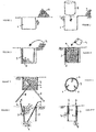
- Figure 1 shows the excavation of a hole 1 in the ground with the excavated material 2 stacked adjacent to the excavation for reuse.
- Figure 2 shows a hollow foundation former 3 being inserted into the hole 1.
- the former 3 could be square, circular, rectangular or any other shape on plan.
- the former 3 may be made of metal resin, fabric or plastics or a composite thereof.
- the former 3 could be rigid, flexible or a combination of rigid and flexible material.
- the former 3 is open at the top and bottom ends.
- the former 3 may be fitted with top, bottom or intermediate stiffening plates. These plates could be solid or consist of a grillage of members.
- Figure 3 shows the excavated material 2 being backfilled into the former 3 to form a new foundation. Any clearance space between the former 3 and the ground surrounding the former 3 may be backfilled with the excavated material and/or with a filler material such as a cementitious grout, resin, expanding resin or other similar material. In alternative embodiments the former 3 could be filled with a filler material such as a cementitious grout, resin, expanding resin, rock, gravel or other similar material without incorporating the excavated material.
- a filler material such as a cementitious grout, resin, expanding resin, rock, gravel or other similar material without incorporating the excavated material.
- Figure 4 shows the backfilled material 2 being filled with a filler material such as a cementitious grout, resin, expanding resin or other similar material 4.
- the filler material fills the voids within the backfilled material 2 and bonds the material to the former 3 to increase the overall strength of the new foundation.
- Material used to infill the voids can either be spread uniformly through the new foundation or be concentrated in a position (e.g. the top or the bottom of a new foundation) depending on the design requirements.
- the filler material may comprise a two component resin where the components are mixed and the resin poured or injected to fill the voids before setting and hardening. Any suitable filler material may be employed as will be familiar to those skilled in the art.
- Figure 5 shows an arrangement where driving one or more anchoring members 5 through the new foundation may increase the overall capacity of the new foundation. This increases the load carrying capacity of the new foundation.
- the anchoring members 5 may be driven either before or after the former 3 is backfilled.
- the anchoring members 5 may be in the form of spikes.
- the spikes 5 may be hollow tubes and may be provided with one or more holes at the lower end and or along the length through which a filler material may be added to distribute the filler material for filling voids in the backfilled material and/or in the ground surrounding the former.
- the upper end of the anchoring member 5 may be closed after the filler material is added, for example with a cap, to seal the anchoring member 5. Pressure may be used to force the filler material out of the holes in the anchoring member.
- the anchoring members 5 may be connected to the top plate, bottom plate or the side walls of the former.
- Figure 6 shows a modification in which the former 3 is optionally strengthened with one or more internal formations 6.
- the formations 6 could be ribs as shown, cross members, or a grillage of interconnecting members.
- the former may be provided with one or more external formations in place of or in addition to one or more internal formations.
- Figure 7 shows a modification in which the ground around and/or below the former 3 is optionally filled with a filler material 4 such as a cementitious grout, resin, expanding resin or other similar material.
- the filler material 4 may be injected through a removable tube 9 inserted into the ground 7 around the perimeter of the former and/or through the former 3 into the ground 8 below the base of the former 3. Injection of filler material 4 around and/or below the former 3 fills any voids and increases the strength of the connection between the former 3 and the adjacent ground and increases its overall load carrying capacity.
- the tube 9 may be provided with one or more holes at the lower end and/or along the length to distribute the filler material for filling voids within the ground surrounding the former.
- Pressure may be used to force the filler material out of the holes in the tube. This may involve use of a pump.
- the filler material is an expanding resin
- closing the upper end may confine the filler material and assist in generating a pressure to force the resin out through the holes into the surrounding area when the filler material expands. This may avoid the need for a pump.
- Figure 8 shows a modification in which the former 3 contains internal fittings 10, 11 to allow a filler material 4 to be injected into the ground 7 around the perimeter of the former 3 and/or into the ground 8 below the former 3 in addition to or in place of the injection of filler material with the separate lance 9 shown in Figure 7 .
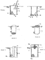
- Figure 9 shows a modification in which the former 3 has a base member 12 and top member 13.
- the base member 12 and top member 13 may be made of the same material as the former 3 or a different material.
- the base member 12 and top member 13 may be separate from the former 3.
- the base member 12 and top member 13 may be solid and may close the open ends of the former 3 and help contain any filler material 4 that is used to bind the backfilled material 2 together and improves the overall strength of the new foundation.
- the foundation former may have a base member 12 only or a top member 13 only.
- the former 3 may have an integral base member 12.
- the base member 12 and the top member 13 may contain holes and or locating sleeves to allow for the placement of the anchoring members shown in figure 5 .
- Figure 10 shows a modification in which the base member 12 has one or more stiffening ribs 15.
- the ribs 15 may improve the strength of the base member 12.
- the ribs 15 may be fitted on the underside of the base member as shown and/or on the topside of the base member 12.
- the base member 12 may be solid or may contain one or more holes.
- Figure 11 shows a modification in which the base member 12 comprises an open grillage.
- the base member 12 could take other forms including a thickened rim around the perimeter of the former or an in situ bed such as concrete.
- Figure 12 shows a modification in which the top member 13 comprises an open grillage.
- the top member 13 could take other forms including a thickened rim around the perimeter of the former.
- Figure 13 shows a modification in which a sleeve 17 is inserted in the foundation before backfilling.
- the sleeve 17 may be used to allow a support member such as a post, column or other similar member (not shown) to be inserted into the foundation.
- the sleeve 17 may be closed at the lower end to prevent ingress of the backfill material and/or filler material.
- the sleeve 17 may extend from the top of the foundation to prevent ingress of the backfill material and/or filler material.
- the sleeve 17 may be provided with a removable cap at the upper end to prevent ingress of the backfill material and/or filler material and/or any other material until the cap member is removed when it is desired to insert a support member into the sleeve.
- the sleeve 17 may be a separate member or may be integral with former 3.
- Figure 14 shows a modification in which a top member 18 is provided with a fitting 19 for connection to a supporting structure.
- the fitting 19 may allow for vertical height adjustment.
- the fitting 19 may comprise a base plate 19a provided with a threaded shank 19b that screws into a threaded hole in the top member 18.
- Figure 15 shows a modification in which a top member 20 contains a hole 21 to allow a support member 22 such as a post to be inserted into the foundation.
- a base member may contain a seating (not shown) to locate and/or support the base of the support member.
- Figure 16 shows a modification in which the support member 22 is pre-fitted with a base element 23 such as a spreader plate.
- the base element 23 could be used in conjunction with the base member 12 or could replace the base member 12.
- the top member 20 may fit over the support member 22.
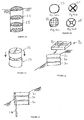
- Figure 17 shows a modification in which the former 3 is provided with one or more strengthening members 24 positioned adjacent the sidewalls of the former 3 during installation to reinforce the sidewalls of the former 3.
- the strengthening members 24 could be rods, plates or other member having any shape required.
- the strengthening members 24 may be located on the inside or outside face of the sidewalls of the former 3. Alternatively or additionally the strengthening members may be located in channels/grooves (not shown) on the inside or outside face of the sidewalls of the former 3.
- the strengthening members 24 could extend below the base of the former 3 which may further increase the strength of the foundation. Alternatively, the strengthening members 24 may be located in the base of the former 3.
- the strengthening members 24 may extend vertically as shown or at an angle to the vertical. Where two strengthening members 24 extend at an angle to the vertical and at opposite angles to each other, this may provide an enhanced anchor to secure and retain the former 3 in situ.
- Figure 18 shows a modification in which two or more formers 3a, 3b, 3c can be stacked one on top of the other to allow the height of the foundation to be varied according to the requirements.
- each former 3a, 3b, 3c may be connected to the adjacent former using interconnecting elements such as lugs and/or using strengthening members 24 as shown on Figure 17 and/or any other suitable means.
- Figure 19 shows a modification in which one or more internal dividing members 25 are provided to strengthen the foundation.
- the members 25 may be arranged horizontally. Where two or more members 25 are provided they can be spaced apart vertically. Where the foundation comprises a stack of formers as shown in Figure 19 , the members 25 may be provided at the junction between adjacent formers. The members 25 may be connected to the adjacent formers in a similar way to that described in Figure 18 . Dividing members 25 may also be provided at the top and or bottom of the stack of formers.
- Figures 20a-20d show a variety of different internal dividing members 25.
- Figure 20a shows a member 25 consisting of a solid plate.
- Figure 20b shows a member 25 consisting of an outer ring and inner spokes (similar to a bicycle wheel).
- Figure 20c shows a member 25 consisting of an outer ring and an inner grillage.
- Figure 20d shows a member 25 consisting of an outer ring and an inner ring or socket connected to the outer ring by spokes. The inner ring or socket may locate a post inserted through the member 25.
- Figure 21 shows a modification in which the dividing members 25 are of increased depth such that a single dividing member 25 or a stack of two or more dividing members 25 one on top of the other and optional connectors between the members may be used as a former.
- Figures 22 and 23 show a rectangular former 3 with a grillage of internal dividing members 25.
- a plurality of formers 3a, 3b, 3c may be stacked one on top of the other to create a level walkway on sloping ground. Adjacent formers may be connected to each other by any of the methods described herein. With this arrangement the loads may be lower and a base member and/or a top member may not be required.
- the grillages could be backfilled with excavated material or imported material such as gravel. Alternatively the grillages could be partly filled with excavated material and partly filled with gravel. Preferably the gravel would be placed in the top to give a walking surface.
- the overall strength of the arrangement could be increased by driving strengthening members 24 through the stack of formers 3a, 3b, 3c and into the ground below similar to Figure 17 .
- the members 4 may extend vertically or at an angle to the vertical and/or at an angle to each other.
- Figure 24 shows a rectangular former 3 with a grillage of internal dividing members 25 similar to Figures 23 and 24 .
- the sidewalls of the former 3 are provided with formations by means of which the formers can be located and arranged side by side and connected together to create a larger level area.
- the formations comprise one or more lugs 26 on two sidewalls and one or more slots 27 on the other two sidewalls.
- Other formations and/or configurations of formations may be employed.
- the former 3 may additionally be provided with a top member 28 to form a paving slab.
- the top member 28 may be made of fiberglass or other suitable material. To reduce the risk of high winds picking up and moving the slab, the former 3 may be backfilled with soil or gravel or any other infill material before fitting the top member 28.
- the former 3 may be provided with internal projections 29 on the sidewalls and/or the dividing members 25 to assist in retaining the infill material and spreading the load onto the ground.
- the former 3 may be provided with a base member 30 to retain the infill material.
- the base member 30 may comprise a fine mesh.
- the base member 30 may be integral with or separate from the former 3.
- two or more formers 3 may be stacked one on top of the other and connected together to take account of changes in ground level and/or to increase the weight of the unit.
- the former 3 may be configured with a lip or other suitable formation on the top face to assist fixing the top member 28 to the former 3. Where several formers 3 are connected together side by side to create a level surface area, the top member 28 may be configured to cover two or more formers.
- the former 3 may be infilled with a filler material. However, this may not be essential in all cases and the invention extends to and includes the formers and use of the formers described herein without the infill material. The invention also extends to and includes formers and use of formers comprising any combination of the features of the formers described herein.
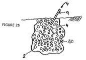
- Figure 25 shows an alternative foundation former 40 made from a flexible material.
- the former 40 may comprise a flexible sheet material.
- the flexible former 40 can be inserted into a hole excavated in the ground and backfilled with the excavated material 2. As a result the former 40 may conform to the profile of the hole.
- the backfill material 2 inside the former 40 may then be strengthened with a filler material 4 such as a cementitious grout, resin, expanding resin or other similar material.
- the filler material fills any voids in the backfilled former and creates a substantially rigid foundation.
- the filler material may be inserted into the backfilled material within the former 40 through a removable tube 9.
- the filler material may be inserted into the ground around the perimeter of the former 40 and or below the former 40 as described previously.
- Pressure may be used to force the filler material out of the holes in the tube. This may involve use of a pump. Alternatively, if the filler material is an expanding resin, closing the upper end may confine the filler material and assist in generating a pressure to force the resin out through the holes into the surrounding area when the filler material expands. This may avoid the need for a pump.
- the foundation 40 may be provided with a sleeve for a supporting structure as described previously.
- the foundation 40 may be provided with a top member and fitting for connection to a supporting structure as described previously.
Landscapes
- Engineering & Computer Science (AREA)
- Structural Engineering (AREA)
- Life Sciences & Earth Sciences (AREA)
- General Engineering & Computer Science (AREA)
- Paleontology (AREA)
- Civil Engineering (AREA)
- Mining & Mineral Resources (AREA)
- General Life Sciences & Earth Sciences (AREA)
- Agronomy & Crop Science (AREA)
- Environmental & Geological Engineering (AREA)
- Soil Sciences (AREA)
- Foundations (AREA)
- Piles And Underground Anchors (AREA)
Abstract
Description
- This invention concerns formers that can be used for a range of applications including, but not limited to spread foundations and ground reinforcements.
- Spread foundations are a traditional form of supporting structures. The supported load is "spread" into the ground through a foundation. In older properties the spread foundation could take the form of corbeled layers of brickwork/stonework and in more modern properties spread foundations are generally constructed from concrete.
- To construct a traditional concrete spread foundation it is necessary to excavate a hole down to ground that is capable of supporting the load. The material excavated is generally "thrown away". This adds to the cost of constructing the foundation.
- Further problems arise where there is restricted access such that the excavation of a hole and removal of the excavated material can be a problem. For some applications such as the construction of refuge platforms provided at intervals along a rail line for use by rail workers and or the installation of signs and signals along a rail line this can present a particular problem and often requires the use specialised equipment on the rail line necessitating closure of the rail line while the work is carried out. Closing the rail line creates problems for train operators and users.
- Ground reinforcements are a traditional form of creating walkways and areas of hardstanding that can be used as a car park or to support structures such as sheds. In the rail industry there is often a requirement to provide an area around electrical equipment to restrict growth of weeds and vegetation to facilitate access for repair and maintenance work. It is common to construct such areas from concrete but in remote locations it is often difficult to get concrete to site and this adds to the cost of using concrete.
- There is a need therefore for alternative methods of constructing foundations and/or ground reinforcements that addresses one or more of the aforementioned problems.
- A first aspect of this invention provides a method of constructing a spread foundation or ground reinforcement including forming a hole in the ground or other substrate, placing a hollow former in the hole and backfilling using the excavated material.
- The combination of the former and excavated material forms the foundation or reinforcement. By using the excavated material as part of the foundation or reinforcement this invention makes spread foundation or ground reinforcement construction more economical, quicker and more environmentally friendly.
- Optionally, the overall strength of the foundation or reinforcement may be increased by adding a filler material such as a cementitious grout, resin, expanding resin or other similar material to the material in the former.
- Optionally, the overall strength of the foundation or reinforcement may be increased by adding a filler material such as a cementitious grout, resin, expanding resin or other similar material below or around the former.
- Optionally, addition of the filler material, for example a cementitious grout, resin, expanding resin or other similar material, in or around or below the former may be controlled by employing one or more tubes inside and/or outside of the former for injecting the material. The tubes may be provided with one or more holes at the lower end and/or along the length of the tube to distribute the filler material. The filler material may be forced out of the tube under pressure. Pressure may be applied using a pump. Alternatively where the filler material is an expandable resin, the pressure may be generated by confining the resin within the tube so that it flows through the holes under the pressure generated by expansion of the resin.
- Where provided, the filler material may be in a form that can flow to fill voids in the backfill material within the former and/or in the soil around and/or below the former and subsequently set or harden to form a substantially rigid foundation or reinforcement.
- Optionally, the load capacity of the foundation or reinforcement may be increased by driving one or more anchoring members into the ground through the foundation. The anchoring members may comprise spikes and could take the form of rods, tubes, plates, angles or other similar forms. The anchoring members may be held into the foundation or reinforcement either by locating holes in top and or bottom sections of the former, locating tubes built into the former or by setting the anchoring members into the soil/grout/resin matrix.
- Optionally, the former may be provided with one or more internal and/or external members such as ribs. Where provided the members may strengthen the former.
- Optionally, the former may be configured to contain the material in the former. It may be that the former can be fitted with a base member and/or a top member. This may provide a further containment to the infill. It may be that the base member and/or top member can be used to provide a location for the anchoring members, where provided, and/or for the fitting of a support structure such as a post or platform. The base member and/or top member hold the post in position and transfer any horizontal loads onto the main former.
- Optionally, the former may be provided with a tubular member such as a sleeve. The sleeve may be located at any desired position within the former and the backfill material may fill the space within the former between the former and the sleeve and locate the sleeve at the desired position. The sleeve may be used to provide a location for fitting a support structure such as a post or platform. The lower end of the sleeve may be closed to prevent ingress of backfill material. The upper end of the sleeve may extend above the foundation. The upper end of the sleeve may be provided with a removable closure cap.
- Optionally, the former may be configured to conform to the profile of the hole. For example, the former may be flexible so that it can mould to the profile of the hole. Where the former is flexible it may be preferred that the excavated material used to backfill the hole may be strengthened with a filler material such as a cementitious grout, resin, expanding resin or other similar material as previously described to form a rigid foundation.
- A second aspect of this invention provides a method of constructing a spread foundation or ground reinforcement including forming a hole in the ground or other substrate, placing a hollow former in the hole and filling the former with a filler material.
- The filler material may comprise the material excavated to form the hole. Alternatively the filler material may comprise any other suitable material such as cementitious grout, resin, expanding resin or other similar material
- The method may comprise any of the features already described in connection with the first aspect of the invention.
- A third aspect of this invention provides a former for use in the method of the first or second aspects of the invention.
- The former may comprise any of the features already described in connection with the first and second aspects of the invention.
- A fourth aspect of the invention provides a spread foundation or ground reinforcement comprising a former and at least one of a top member, a base member and an infill material.
- The spread foundation or ground reinforcement may comprise any of the features described in connection with the preceding aspects of the invention.
- A fifth aspect of the invention provides a load bearing construction member comprising a former and at least one of a top member, a base member and an infill material.
- The load bearing construction member may comprise any of the features described in connection with the preceding aspects of the invention
- The invention will now be described in more detail by way of example only with reference to the accompanying drawings in which like reference numerals indicate corresponding parts and wherein:
-
Figure 1 shows the excavation of a hole for the new foundation; -
Figure 2 shows the hollow former being inserted into the hole; -
Figure 3 shows the excavated material being put back into the former; -
Figure 4 shows the strengthening of the backfilled material; -
Figure 5 shows the location of spikes designed to improve the capacity of the foundation; -
Figure 6 shows internal strengthening ribs to the hollow foundation former; -
Figure 7 shows consolidation of the ground around the new foundation; -
Figure 8 shows inserts to allow material to be injected around and below the foundation; -
Figure 9 shows top and bottom plates to the foundation; -
Figure 10 shows the bottom plate fitted with strengthening ribs; -
Figure 11 shows the bottom plate with a grillage; -
Figure 12 shows the top plate with a grillage; -
Figure 13 shows a hollow central sleeve to the centre of the foundation; -
Figure 14 shows an adjustable head to the foundation; -
Figure 15 shows the former with a support member; -
Figure 16 shows the support member with a support base; -
Figure 17 shows the former with strengthening members; -
Figure 18 shows a plurality of formers stacked one on top of the other; -
Figure 19 shows the former stack with internal dividing members; -
Figure 20 shows alternative forms of dividing members; -
Figure 21 shows a former comprising a stack of dividing members; -
Figure 22 shows a plurality of rectangular formers stacked one on top of the other; -
Figure 23 shows the former stack with strengthening members; -
Figure 24 shows a former suitable for use as a paving slab; and -
Figure 25 shows a foundation former made from a flexible material. -
Figure 1 shows the excavation of ahole 1 in the ground with the excavatedmaterial 2 stacked adjacent to the excavation for reuse. -
Figure 2 shows a hollow foundation former 3 being inserted into thehole 1. The former 3 could be square, circular, rectangular or any other shape on plan. The former 3 may be made of metal resin, fabric or plastics or a composite thereof. The former 3 could be rigid, flexible or a combination of rigid and flexible material. In this embodiment, the former 3 is open at the top and bottom ends. In other embodiments the former 3 may be fitted with top, bottom or intermediate stiffening plates. These plates could be solid or consist of a grillage of members. -
Figure 3 shows the excavatedmaterial 2 being backfilled into the former 3 to form a new foundation. Any clearance space between the former 3 and the ground surrounding the former 3 may be backfilled with the excavated material and/or with a filler material such as a cementitious grout, resin, expanding resin or other similar material. In alternative embodiments the former 3 could be filled with a filler material such as a cementitious grout, resin, expanding resin, rock, gravel or other similar material without incorporating the excavated material. -
Figure 4 shows the backfilledmaterial 2 being filled with a filler material such as a cementitious grout, resin, expanding resin or othersimilar material 4. The filler material fills the voids within the backfilledmaterial 2 and bonds the material to the former 3 to increase the overall strength of the new foundation. Material used to infill the voids can either be spread uniformly through the new foundation or be concentrated in a position (e.g. the top or the bottom of a new foundation) depending on the design requirements. The filler material may comprise a two component resin where the components are mixed and the resin poured or injected to fill the voids before setting and hardening. Any suitable filler material may be employed as will be familiar to those skilled in the art. -
Figure 5 shows an arrangement where driving one ormore anchoring members 5 through the new foundation may increase the overall capacity of the new foundation. This increases the load carrying capacity of the new foundation. The anchoringmembers 5 may be driven either before or after the former 3 is backfilled. The anchoringmembers 5 may be in the form of spikes. Thespikes 5 may be hollow tubes and may be provided with one or more holes at the lower end and or along the length through which a filler material may be added to distribute the filler material for filling voids in the backfilled material and/or in the ground surrounding the former. The upper end of the anchoringmember 5 may be closed after the filler material is added, for example with a cap, to seal the anchoringmember 5. Pressure may be used to force the filler material out of the holes in the anchoring member. This may involve use of a pump. Alternatively, if the filler material is an expanding resin, closing the upper end may confine the filler material and assist in generating a pressure to force the resin out through the holes into the surrounding area when the filler material expands. This may avoid the need for a pump. The anchoringmembers 5 may be connected to the top plate, bottom plate or the side walls of the former. -
Figure 6 shows a modification in which the former 3 is optionally strengthened with one or moreinternal formations 6. Theformations 6 could be ribs as shown, cross members, or a grillage of interconnecting members. In other embodiments the former may be provided with one or more external formations in place of or in addition to one or more internal formations. -
Figure 7 shows a modification in which the ground around and/or below the former 3 is optionally filled with afiller material 4 such as a cementitious grout, resin, expanding resin or other similar material. Thefiller material 4 may be injected through aremovable tube 9 inserted into theground 7 around the perimeter of the former and/or through the former 3 into theground 8 below the base of the former 3. Injection offiller material 4 around and/or below the former 3 fills any voids and increases the strength of the connection between the former 3 and the adjacent ground and increases its overall load carrying capacity. Thetube 9 may be provided with one or more holes at the lower end and/or along the length to distribute the filler material for filling voids within the ground surrounding the former. Pressure may be used to force the filler material out of the holes in the tube. This may involve use of a pump. Alternatively, if the filler material is an expanding resin, closing the upper end may confine the filler material and assist in generating a pressure to force the resin out through the holes into the surrounding area when the filler material expands. This may avoid the need for a pump. -
Figure 8 shows a modification in which the former 3 containsinternal fittings 10, 11 to allow afiller material 4 to be injected into theground 7 around the perimeter of the former 3 and/or into theground 8 below the former 3 in addition to or in place of the injection of filler material with theseparate lance 9 shown inFigure 7 . -
Figure 9 shows a modification in which the former 3 has abase member 12 andtop member 13. Thebase member 12 andtop member 13 may be made of the same material as the former 3 or a different material. Thebase member 12 andtop member 13 may be separate from the former 3. Thebase member 12 andtop member 13 may be solid and may close the open ends of the former 3 and help contain anyfiller material 4 that is used to bind the backfilledmaterial 2 together and improves the overall strength of the new foundation. In other embodiments the foundation former may have abase member 12 only or atop member 13 only. In other embodiments the former 3 may have anintegral base member 12. Thebase member 12 and thetop member 13 may contain holes and or locating sleeves to allow for the placement of the anchoring members shown infigure 5 . -
Figure 10 shows a modification in which thebase member 12 has one ormore stiffening ribs 15. Theribs 15 may improve the strength of thebase member 12. Theribs 15 may be fitted on the underside of the base member as shown and/or on the topside of thebase member 12. Thebase member 12 may be solid or may contain one or more holes. -
Figure 11 shows a modification in which thebase member 12 comprises an open grillage. Thebase member 12 could take other forms including a thickened rim around the perimeter of the former or an in situ bed such as concrete. -
Figure 12 shows a modification in which thetop member 13 comprises an open grillage. Thetop member 13 could take other forms including a thickened rim around the perimeter of the former. -
Figure 13 shows a modification in which asleeve 17 is inserted in the foundation before backfilling. Thesleeve 17 may be used to allow a support member such as a post, column or other similar member (not shown) to be inserted into the foundation. Thesleeve 17 may be closed at the lower end to prevent ingress of the backfill material and/or filler material. Thesleeve 17 may extend from the top of the foundation to prevent ingress of the backfill material and/or filler material. Thesleeve 17 may be provided with a removable cap at the upper end to prevent ingress of the backfill material and/or filler material and/or any other material until the cap member is removed when it is desired to insert a support member into the sleeve. Thesleeve 17 may be a separate member or may be integral with former 3. -
Figure 14 shows a modification in which atop member 18 is provided with a fitting 19 for connection to a supporting structure. The fitting 19 may allow for vertical height adjustment. For example the fitting 19 may comprise a base plate 19a provided with a threaded shank 19b that screws into a threaded hole in thetop member 18. -
Figure 15 shows a modification in which atop member 20 contains ahole 21 to allow asupport member 22 such as a post to be inserted into the foundation. Where provided, a base member may contain a seating (not shown) to locate and/or support the base of the support member. -
Figure 16 shows a modification in which thesupport member 22 is pre-fitted with abase element 23 such as a spreader plate. Thebase element 23 could be used in conjunction with thebase member 12 or could replace thebase member 12. Thetop member 20 may fit over thesupport member 22. -
Figure 17 shows a modification in which the former 3 is provided with one ormore strengthening members 24 positioned adjacent the sidewalls of the former 3 during installation to reinforce the sidewalls of the former 3. The strengtheningmembers 24 could be rods, plates or other member having any shape required. The strengtheningmembers 24 may be located on the inside or outside face of the sidewalls of the former 3. Alternatively or additionally the strengthening members may be located in channels/grooves (not shown) on the inside or outside face of the sidewalls of the former 3. The strengtheningmembers 24 could extend below the base of the former 3 which may further increase the strength of the foundation. Alternatively, the strengtheningmembers 24 may be located in the base of the former 3. The strengtheningmembers 24 may extend vertically as shown or at an angle to the vertical. Where two strengtheningmembers 24 extend at an angle to the vertical and at opposite angles to each other, this may provide an enhanced anchor to secure and retain the former 3 in situ. -
Figure 18 shows a modification in which two ormore formers members 24 as shown onFigure 17 and/or any other suitable means. -
Figure 19 shows a modification in which one or moreinternal dividing members 25 are provided to strengthen the foundation. Themembers 25 may be arranged horizontally. Where two ormore members 25 are provided they can be spaced apart vertically. Where the foundation comprises a stack of formers as shown inFigure 19 , themembers 25 may be provided at the junction between adjacent formers. Themembers 25 may be connected to the adjacent formers in a similar way to that described inFigure 18 . Dividingmembers 25 may also be provided at the top and or bottom of the stack of formers. -
Figures 20a-20d show a variety of differentinternal dividing members 25.Figure 20a shows amember 25 consisting of a solid plate.Figure 20b shows amember 25 consisting of an outer ring and inner spokes (similar to a bicycle wheel).Figure 20c shows amember 25 consisting of an outer ring and an inner grillage.Figure 20d shows amember 25 consisting of an outer ring and an inner ring or socket connected to the outer ring by spokes. The inner ring or socket may locate a post inserted through themember 25. -
Figure 21 shows a modification in which the dividingmembers 25 are of increased depth such that asingle dividing member 25 or a stack of two ormore dividing members 25 one on top of the other and optional connectors between the members may be used as a former. -
Figures 22 and 23 show a rectangular former 3 with a grillage ofinternal dividing members 25. A plurality offormers members 24 through the stack offormers Figure 17 . Themembers 4 may extend vertically or at an angle to the vertical and/or at an angle to each other. -
Figure 24 shows a rectangular former 3 with a grillage ofinternal dividing members 25 similar toFigures 23 and24 . Additionally, the sidewalls of the former 3 are provided with formations by means of which the formers can be located and arranged side by side and connected together to create a larger level area. In this embodiment, the formations comprise one ormore lugs 26 on two sidewalls and one ormore slots 27 on the other two sidewalls. Other formations and/or configurations of formations may be employed. The former 3 may additionally be provided with atop member 28 to form a paving slab. Thetop member 28 may be made of fiberglass or other suitable material. To reduce the risk of high winds picking up and moving the slab, the former 3 may be backfilled with soil or gravel or any other infill material before fitting thetop member 28. The former 3 may be provided withinternal projections 29 on the sidewalls and/or the dividingmembers 25 to assist in retaining the infill material and spreading the load onto the ground. Alternatively or additionally, the former 3 may be provided with abase member 30 to retain the infill material. Thebase member 30 may comprise a fine mesh. Thebase member 30 may be integral with or separate from the former 3. In some applications, two ormore formers 3 may be stacked one on top of the other and connected together to take account of changes in ground level and/or to increase the weight of the unit. The former 3 may be configured with a lip or other suitable formation on the top face to assist fixing thetop member 28 to the former 3. Whereseveral formers 3 are connected together side by side to create a level surface area, thetop member 28 may be configured to cover two or more formers. - In the preceding embodiments of the invention, the former 3 may be infilled with a filler material. However, this may not be essential in all cases and the invention extends to and includes the formers and use of the formers described herein without the infill material. The invention also extends to and includes formers and use of formers comprising any combination of the features of the formers described herein.
-
Figure 25 shows an alternative foundation former 40 made from a flexible material. For example the former 40 may comprise a flexible sheet material. The flexible former 40 can be inserted into a hole excavated in the ground and backfilled with the excavatedmaterial 2. As a result the former 40 may conform to the profile of the hole. Thebackfill material 2 inside the former 40 may then be strengthened with afiller material 4 such as a cementitious grout, resin, expanding resin or other similar material. The filler material fills any voids in the backfilled former and creates a substantially rigid foundation. The filler material may be inserted into the backfilled material within the former 40 through aremovable tube 9. The filler material may be inserted into the ground around the perimeter of the former 40 and or below the former 40 as described previously. Pressure may be used to force the filler material out of the holes in the tube. This may involve use of a pump. Alternatively, if the filler material is an expanding resin, closing the upper end may confine the filler material and assist in generating a pressure to force the resin out through the holes into the surrounding area when the filler material expands. This may avoid the need for a pump. The foundation 40 may be provided with a sleeve for a supporting structure as described previously. The foundation 40 may be provided with a top member and fitting for connection to a supporting structure as described previously.
Claims (15)
- A method of constructing a spread foundation or ground reinforcement including forming a hole in the ground or other substrate, placing a hollow former in the hole and backfilling using the excavated material.
- The method of claim 1 further comprising adding a filler material such as a cementitious grout, resin, expanding resin or other similar material to the material in the former.
- The method of claim 1 or claim 2 further comprising adding a filler material such as a cementitious grout, resin, expanding resin or other similar material below or around the former.
- The method of claim 2 or claim 3 wherein addition of the filler material in or around or below the former is controlled by employing one or more tubes inside and/or outside of the former for injecting the material, wherein, preferably, the filler material is forced out of the one or more tubes under pressure.
- The method of claim 4 wherein one or more holes is provided at a lower end and/or along the length of the or more tubes to distribute the filler material.
- The method of any of claims 2 to 5 wherein the filler material is in a form that can flow to fill voids in the backfill material within the former and/or in the soil around and/or below the former and subsequently set or harden to form a substantially rigid foundation or reinforcement.
- The method of any of the preceding claims further comprising driving one or more anchoring members into the ground through the foundation.
- The method of claim 7 wherein the one or more anchoring members comprise spikes.
- The method of claim 7 or claim 8 wherein the one or more anchoring members are held into the foundation or reinforcement either by locating holes in top and or bottom sections of the former, locating tubes built into the former or by setting the anchoring members into the soil/grout/resin matrix.
- The method of any of the preceding claims wherein the former is provided with one or more internal and/or external strengthening members.
- The method of any preceding claim wherein the former is configured to contain the material in the former.
- The method of any preceding claim wherein the former is provided with a base member and/or a top member.
- The method of claim 12 wherein the base member and/or top member are adapted to provide a location for anchoring members and/or for fitting a support structure.
- The method of any preceding claim wherein the former is provided with a tubular member located within the former and the backfill material fills the space within the former between the former and the sleeve and locates the sleeve at a desired position.
- The method of claim 1 wherein the former is conformable to the profile of the hole.
Applications Claiming Priority (2)
| Application Number | Priority Date | Filing Date | Title |
|---|---|---|---|
| GBGB1513490.1A GB201513490D0 (en) | 2015-07-30 | 2015-07-30 | Foundation improvements |
| GB1604093.3A GB2541043B (en) | 2015-07-30 | 2016-03-10 | Formers |
Publications (1)
| Publication Number | Publication Date |
|---|---|
| EP3124705A1 true EP3124705A1 (en) | 2017-02-01 |
Family
ID=54062941
Family Applications (1)
| Application Number | Title | Priority Date | Filing Date |
|---|---|---|---|
| EP16182114.5A Withdrawn EP3124705A1 (en) | 2015-07-30 | 2016-07-30 | Formers |
Country Status (2)
| Country | Link |
|---|---|
| EP (1) | EP3124705A1 (en) |
| GB (2) | GB201513490D0 (en) |
Cited By (3)
| Publication number | Priority date | Publication date | Assignee | Title |
|---|---|---|---|---|
| CN111172984A (en) * | 2020-02-17 | 2020-05-19 | 中冶建工集团有限公司 | Manual hole digging pile dado template convenient to use |
| CN113374507A (en) * | 2021-06-29 | 2021-09-10 | 中国十九冶集团有限公司 | Template device and template supporting method for underground deep hole retaining wall |
| CN117507113A (en) * | 2023-07-05 | 2024-02-06 | 新疆苏中建设工程有限公司 | A kind of concrete structure hole forming device |
Citations (9)
| Publication number | Priority date | Publication date | Assignee | Title |
|---|---|---|---|---|
| US3099911A (en) * | 1958-10-08 | 1963-08-06 | Lee A Turzillo | Means of grouting or concreting |
| FR2616460A1 (en) * | 1987-06-10 | 1988-12-16 | Etu Pilotage Sarl Const | Device for anchoring into concrete for a support post, particularly for signs using a sealing bar |
| EP0682152A1 (en) * | 1994-05-09 | 1995-11-15 | Tellura | Means for anchoring an object to the ground |
| JPH11124865A (en) * | 1997-10-20 | 1999-05-11 | Osamu Kuroishi | Pillar structure foundation |
| DE10025966A1 (en) * | 2000-05-25 | 2001-12-06 | Bauer Spezialtiefbau | Ground reinforcement by sleeved body insertion encloses insert body in bottom-closed sleeve before or during ground insertion ready for backfilling sleeve at target depth downhole. |
| GB2460447A (en) * | 2008-05-30 | 2009-12-02 | David Thomas Hill | Buried post base |
| KR20100093416A (en) * | 2009-02-16 | 2010-08-25 | 한국전력기술 주식회사 | Power transmission steel tower deep foundation construction |
| US20100277290A1 (en) * | 2009-03-18 | 2010-11-04 | Knudsen N Eric | Post sleeve assembly |
| DE102010024607A1 (en) * | 2010-06-22 | 2011-12-22 | Eduard Eigenschenk | Foundation pile for increasing load-carrying capacity in soil, has different layers provided with aggregate with geo-textile sacks, geo-textile trajectory and/or geo-textile fabric and between top/under-covered layers of thin aggregate |
Family Cites Families (6)
| Publication number | Priority date | Publication date | Assignee | Title |
|---|---|---|---|---|
| GB0029498D0 (en) * | 2000-12-02 | 2001-01-17 | Oceans Engineering Ltd | A method of making a foundation |
| JP2004092025A (en) * | 2002-08-29 | 2004-03-25 | Daia Soil Kk | Foundation pile and construction method thereof |
| CA2443759C (en) * | 2003-10-17 | 2008-09-16 | Casey Moroschan | Foam pile system |
| JP4020858B2 (en) * | 2003-11-21 | 2007-12-12 | 株式会社福田組 | Manufacturing method for underground structures |
| ITPR20070066A1 (en) * | 2007-08-28 | 2009-02-28 | Tecsoil Srl | PROCEDURE FOR CONSOLIDATING TYPES OF JET GROUTING WITH A HIGH SAVINGS OF CONSOLIDATING PRODUCT |
| IT1398675B1 (en) * | 2009-09-29 | 2013-03-08 | Kappazeta S P A | METHOD OF CONSOLIDATION OF SOIL BY MEANS OF EXPANDING RESIN INJECTION |
-
2015
- 2015-07-30 GB GBGB1513490.1A patent/GB201513490D0/en not_active Ceased
-
2016
- 2016-03-10 GB GB1604093.3A patent/GB2541043B/en active Active
- 2016-07-30 EP EP16182114.5A patent/EP3124705A1/en not_active Withdrawn
Patent Citations (9)
| Publication number | Priority date | Publication date | Assignee | Title |
|---|---|---|---|---|
| US3099911A (en) * | 1958-10-08 | 1963-08-06 | Lee A Turzillo | Means of grouting or concreting |
| FR2616460A1 (en) * | 1987-06-10 | 1988-12-16 | Etu Pilotage Sarl Const | Device for anchoring into concrete for a support post, particularly for signs using a sealing bar |
| EP0682152A1 (en) * | 1994-05-09 | 1995-11-15 | Tellura | Means for anchoring an object to the ground |
| JPH11124865A (en) * | 1997-10-20 | 1999-05-11 | Osamu Kuroishi | Pillar structure foundation |
| DE10025966A1 (en) * | 2000-05-25 | 2001-12-06 | Bauer Spezialtiefbau | Ground reinforcement by sleeved body insertion encloses insert body in bottom-closed sleeve before or during ground insertion ready for backfilling sleeve at target depth downhole. |
| GB2460447A (en) * | 2008-05-30 | 2009-12-02 | David Thomas Hill | Buried post base |
| KR20100093416A (en) * | 2009-02-16 | 2010-08-25 | 한국전력기술 주식회사 | Power transmission steel tower deep foundation construction |
| US20100277290A1 (en) * | 2009-03-18 | 2010-11-04 | Knudsen N Eric | Post sleeve assembly |
| DE102010024607A1 (en) * | 2010-06-22 | 2011-12-22 | Eduard Eigenschenk | Foundation pile for increasing load-carrying capacity in soil, has different layers provided with aggregate with geo-textile sacks, geo-textile trajectory and/or geo-textile fabric and between top/under-covered layers of thin aggregate |
Cited By (3)
| Publication number | Priority date | Publication date | Assignee | Title |
|---|---|---|---|---|
| CN111172984A (en) * | 2020-02-17 | 2020-05-19 | 中冶建工集团有限公司 | Manual hole digging pile dado template convenient to use |
| CN113374507A (en) * | 2021-06-29 | 2021-09-10 | 中国十九冶集团有限公司 | Template device and template supporting method for underground deep hole retaining wall |
| CN117507113A (en) * | 2023-07-05 | 2024-02-06 | 新疆苏中建设工程有限公司 | A kind of concrete structure hole forming device |
Also Published As
| Publication number | Publication date |
|---|---|
| GB2541043B (en) | 2021-04-21 |
| GB201604093D0 (en) | 2016-04-20 |
| GB201513490D0 (en) | 2015-09-16 |
| GB2541043A (en) | 2017-02-08 |
Similar Documents
| Publication | Publication Date | Title |
|---|---|---|
| CN110042716B (en) | Widening construction method for high-fill roadbed with foamed light soil | |
| US11976431B2 (en) | Methods for constructing tensionless concrete pier foundations and foundations constructed thereby | |
| US20010046415A1 (en) | Concrete foundation pierhead and method of lifting a foundation using a jack assembly | |
| KR100933660B1 (en) | Masonry support structure and construction method | |
| CN106759448A (en) | A kind of sunk type agricultural greenhouse photovoltaic bracket foundation structure and its construction method | |
| KR101220256B1 (en) | Retaining wall structure | |
| EP2698476B1 (en) | Method for the construction of an offshore structure and foundation for an offshore structure | |
| KR101118263B1 (en) | Rain retaining facility and constructing method thereof using precast concrete block | |
| KR101039554B1 (en) | Mixed pile combining drilled pile and buried pile and method of construction | |
| CN214940212U (en) | Deep foundation pit supporting device | |
| JP5124007B2 (en) | Retaining wall construction method | |
| GB2541043A (en) | Formers | |
| CN107503355B (en) | Externally-arranged rear-inserted steel type double-row pile foundation pit supporting system and construction method thereof | |
| US4999966A (en) | Method of forming an-before "immured" | |
| US6594968B2 (en) | Method of making a foundation | |
| JP6345328B1 (en) | Original position building method and original position structure | |
| JPH0610344A (en) | How to check and increase bearing capacity of cast-in-place piles | |
| KR101021913B1 (en) | Order temporary construction method for earthquake construction | |
| CN109736318A (en) | Tunnel foundation ditch construction method | |
| KR20130142443A (en) | Foundation construction of bus stop using concrete block and method for constructionn the same | |
| KR20130073336A (en) | Pile structure and construction methods | |
| CN207513221U (en) | A kind of structure of post-tensioned prestressing foundation stabilization | |
| US10077539B1 (en) | Wall and retaining members and fluidizing installation of retaining members | |
| KR102613254B1 (en) | Self-standing fixing type pile and construction method of earth retaining facilities including it | |
| JP7051058B2 (en) | Repair method for existing irrigation canals |
Legal Events
| Date | Code | Title | Description |
|---|---|---|---|
| PUAI | Public reference made under article 153(3) epc to a published international application that has entered the european phase |
Free format text: ORIGINAL CODE: 0009012 |
|
| STAA | Information on the status of an ep patent application or granted ep patent |
Free format text: STATUS: THE APPLICATION HAS BEEN PUBLISHED |
|
| AK | Designated contracting states |
Kind code of ref document: A1 Designated state(s): AL AT BE BG CH CY CZ DE DK EE ES FI FR GB GR HR HU IE IS IT LI LT LU LV MC MK MT NL NO PL PT RO RS SE SI SK SM TR |
|
| AX | Request for extension of the european patent |
Extension state: BA ME |
|
| STAA | Information on the status of an ep patent application or granted ep patent |
Free format text: STATUS: REQUEST FOR EXAMINATION WAS MADE |
|
| 17P | Request for examination filed |
Effective date: 20170731 |
|
| RBV | Designated contracting states (corrected) |
Designated state(s): AL AT BE BG CH CY CZ DE DK EE ES FI FR GB GR HR HU IE IS IT LI LT LU LV MC MK MT NL NO PL PT RO RS SE SI SK SM TR |
|
| STAA | Information on the status of an ep patent application or granted ep patent |
Free format text: STATUS: EXAMINATION IS IN PROGRESS |
|
| 17Q | First examination report despatched |
Effective date: 20171117 |
|
| STAA | Information on the status of an ep patent application or granted ep patent |
Free format text: STATUS: THE APPLICATION IS DEEMED TO BE WITHDRAWN |
|
| 18D | Application deemed to be withdrawn |
Effective date: 20220827 |