EP3124342B1 - Method for controlling one or more brakes of a vehicle - Google Patents
Method for controlling one or more brakes of a vehicle Download PDFInfo
- Publication number
- EP3124342B1 EP3124342B1 EP16181579.0A EP16181579A EP3124342B1 EP 3124342 B1 EP3124342 B1 EP 3124342B1 EP 16181579 A EP16181579 A EP 16181579A EP 3124342 B1 EP3124342 B1 EP 3124342B1
- Authority
- EP
- European Patent Office
- Prior art keywords
- brake
- vehicle
- brakes
- braking
- during
- Prior art date
- Legal status (The legal status is an assumption and is not a legal conclusion. Google has not performed a legal analysis and makes no representation as to the accuracy of the status listed.)
- Active
Links
- 238000000034 method Methods 0.000 title claims description 18
- 238000011156 evaluation Methods 0.000 claims description 19
- 230000005540 biological transmission Effects 0.000 description 3
- 238000011161 development Methods 0.000 description 3
- 230000018109 developmental process Effects 0.000 description 3
- 230000006866 deterioration Effects 0.000 description 2
- 230000000694 effects Effects 0.000 description 2
- 230000002411 adverse Effects 0.000 description 1
- 230000009286 beneficial effect Effects 0.000 description 1
- 238000001816 cooling Methods 0.000 description 1
- 230000008878 coupling Effects 0.000 description 1
- 238000010168 coupling process Methods 0.000 description 1
- 238000005859 coupling reaction Methods 0.000 description 1
- 230000001186 cumulative effect Effects 0.000 description 1
- 230000001419 dependent effect Effects 0.000 description 1
- 238000010586 diagram Methods 0.000 description 1
Images

Classifications
-
- B—PERFORMING OPERATIONS; TRANSPORTING
- B60—VEHICLES IN GENERAL
- B60T—VEHICLE BRAKE CONTROL SYSTEMS OR PARTS THEREOF; BRAKE CONTROL SYSTEMS OR PARTS THEREOF, IN GENERAL; ARRANGEMENT OF BRAKING ELEMENTS ON VEHICLES IN GENERAL; PORTABLE DEVICES FOR PREVENTING UNWANTED MOVEMENT OF VEHICLES; VEHICLE MODIFICATIONS TO FACILITATE COOLING OF BRAKES
- B60T17/00—Component parts, details, or accessories of power brake systems not covered by groups B60T8/00, B60T13/00 or B60T15/00, or presenting other characteristic features
- B60T17/18—Safety devices; Monitoring
- B60T17/22—Devices for monitoring or checking brake systems; Signal devices
- B60T17/221—Procedure or apparatus for checking or keeping in a correct functioning condition of brake systems
-
- B—PERFORMING OPERATIONS; TRANSPORTING
- B60—VEHICLES IN GENERAL
- B60T—VEHICLE BRAKE CONTROL SYSTEMS OR PARTS THEREOF; BRAKE CONTROL SYSTEMS OR PARTS THEREOF, IN GENERAL; ARRANGEMENT OF BRAKING ELEMENTS ON VEHICLES IN GENERAL; PORTABLE DEVICES FOR PREVENTING UNWANTED MOVEMENT OF VEHICLES; VEHICLE MODIFICATIONS TO FACILITATE COOLING OF BRAKES
- B60T8/00—Arrangements for adjusting wheel-braking force to meet varying vehicular or ground-surface conditions, e.g. limiting or varying distribution of braking force
- B60T8/17—Using electrical or electronic regulation means to control braking
- B60T8/1701—Braking or traction control means specially adapted for particular types of vehicles
- B60T8/1708—Braking or traction control means specially adapted for particular types of vehicles for lorries or tractor-trailer combinations
-
- B—PERFORMING OPERATIONS; TRANSPORTING
- B60—VEHICLES IN GENERAL
- B60T—VEHICLE BRAKE CONTROL SYSTEMS OR PARTS THEREOF; BRAKE CONTROL SYSTEMS OR PARTS THEREOF, IN GENERAL; ARRANGEMENT OF BRAKING ELEMENTS ON VEHICLES IN GENERAL; PORTABLE DEVICES FOR PREVENTING UNWANTED MOVEMENT OF VEHICLES; VEHICLE MODIFICATIONS TO FACILITATE COOLING OF BRAKES
- B60T8/00—Arrangements for adjusting wheel-braking force to meet varying vehicular or ground-surface conditions, e.g. limiting or varying distribution of braking force
- B60T8/17—Using electrical or electronic regulation means to control braking
- B60T8/172—Determining control parameters used in the regulation, e.g. by calculations involving measured or detected parameters
-
- B—PERFORMING OPERATIONS; TRANSPORTING
- B60—VEHICLES IN GENERAL
- B60T—VEHICLE BRAKE CONTROL SYSTEMS OR PARTS THEREOF; BRAKE CONTROL SYSTEMS OR PARTS THEREOF, IN GENERAL; ARRANGEMENT OF BRAKING ELEMENTS ON VEHICLES IN GENERAL; PORTABLE DEVICES FOR PREVENTING UNWANTED MOVEMENT OF VEHICLES; VEHICLE MODIFICATIONS TO FACILITATE COOLING OF BRAKES
- B60T2270/00—Further aspects of brake control systems not otherwise provided for
- B60T2270/40—Failsafe aspects of brake control systems
- B60T2270/406—Test-mode; Self-diagnosis
Definitions
- the invention relates to a method for controlling one or more brakes, in particular disc brakes, of a brake system for a vehicle, in particular for a trailer vehicle.
- Fig. 1 shows a schematic representation of a vehicle brake system for a vehicle with here by way of example four disc brakes 1, 2, 3, 4 distributed on two axles 5a (front axle, also referred to as VA), 5b (rear axle, also HA), each with two brake pads 6a, 6b exhibit.
- the vehicle is preferably, in particular, a utility vehicle.
- the vehicle can also be a powered vehicle, in particular a towing vehicle, or a trailer vehicle.
- the brake linings 6a, 6b are each pressed against brake disks, not shown here, of the disk brakes 1-4 in order to brake the vehicle.
- the brake linings 6a, 6b and the brake disc wear out.
- wear sensors 7 In order to determine the wear of the brake linings 6a, 6b and the brake disc as a sum signal, it is known to connect wear sensors 7 to the four (or more) disc brakes 1 - 4 here, each via a connection such as cable 8 or wirelessly to an evaluation and control device 9 to connect.
- This can - in the prior art and also in the invention - be designed as part of a superordinate, not shown here - vehicle condition determination and information system of the vehicle.
- the four disc brakes 1 - 4 each have one of the pad wear sensors 7 - hereinafter also referred to as individual sensors - whose outputs are each connected to the evaluation device 9 via one of the cables 8 so that the evaluation device 9 can be used on this during operation of the vehicle Information about the respective wear condition of the brake linings 6a, 6b of the disc brakes is available (see e.g. EP 0 590 388 B1 ).
- the DE 101 50 047 A1 It is also known to determine the energy that occurs during one or more braking operations, to compare this braking energy with a braking energy limit value and, if this limit value is exceeded, to carry out an adjustment movement on the otherwise compressed air-operated disc brakes to compensate for the wear that has occurred.
- the braking energy is calculated directly from the braking torque and the wheel rotation angle without additional sensors.
- the wheel rotation angle is preferably determined by means of an ABS system with a pole wheel sensor, which is always present in modern brake systems and therefore does not mean any additional expenditure in terms of equipment.
- the braking torque is also preferred in a simple manner from the brake cylinder pressure, in particular a pneumatically actuated pressure Brake cylinder, determines which one is also sent to an EBS or ABS control computer or an evaluation and control device. Appropriately - this can be determined empirically - an adjustment is initiated each time an energy limit value of 2 to 8 MJ, in particular 5 MJ is exceeded, in order to keep the frequency of the adjustment processes relatively low and to always maintain sufficient braking safety.
- the angle of rotation of the wheel is preferably determined directly via a speed sensor that is required, for example, for an ABS and / or EBS function of a brake system for brake control and is therefore available.
- the speed sensor consists of a pole wheel, which rotates with the wheel hub and a stationary encoder, which registers the moving teeth, magnetic coils, etc. of the pole wheel with a voltage pulse. With 100 teeth per pole wheel, for example, one pulse corresponds to a wheel rotation angle of 3.6 °. By adding up these pulses, the evaluation device determines the wheel rotation angle during the braking phase.
- the converted braking energy is thus determined by simply combining the brake cylinder pressure signal with the number of wheel rotation pulses.
- the formulas given are examples and do not necessarily have to be used to determine the braking energy. They are particularly suitable for disc brakes with electromotive or pneumatic actuation and with a floating, fixed or sliding caliper.
- the adjustment system preferably comprises at least one of the electromotive adjustment devices on both sides of the brake disc.
- the brake cylinder pressure during braking is usually determined from brake pedal information and loading information and adjusted in order to achieve the desired braking.
- the deceleration is the quotient of the braking force and the weight of the vehicle.
- the object of the invention is to create a simple method with which disadvantageous developments in the coefficient of friction of the brake linings of a vehicle brake system, in particular a trailer vehicle brake system, can be counteracted at an early stage.
- the energy input for a current braking and / or for one or more future braking operations is defined - for example within the permitted framework of ECE R13. This can be done, for example, by modulating a brake cylinder pressure that is higher than would be set or would be at least required as a result of current or future parameters - such as the characteristics of the brake pedal actuation, speed and possibly the load status of the vehicle - without considering the braking energy consideration . During these braking operations, this leads to a higher energy input and higher temperatures on the brake linings. Disadvantageous changes in the brake lining coefficient of friction can thus be reduced or even completely avoided.
- Disc brakes in particular compressed air-actuated disc brakes, are preferably used as the brakes used. In principle, however, the invention is also suitable for drum brakes.
- the energy input can, for example - but this is not mandatory - with that in the DE 101 50 047 A1 described method can be determined.
- step d) the energy input during the current braking operation and / or during one or more future braking operations is preferably and simply increased by setting a brake cylinder pressure that is higher than it is due to the current braking operation or future parameters such as a brake pedal actuation, a vehicle speed and a load condition of the vehicle would be at least required for the respective braking.
- step d) the energy input during the current braking and / or during one or more future braking operations is increased so that a temperature of at least 150 ° C or more on the brake linings of the brakes is achieved.
- Figure 1b shows a vehicle brake system for a vehicle, which has, for example, four disc brakes 1, 2, 3, 4 distributed on two axles 5a, b, each having two brake linings 6a, 6b. During braking, these brake linings are to be pressed or pressed against a brake disc (not shown here) with friction.
- the vehicle can in particular be an access vehicle or a trailer vehicle.
- the disc brakes are preferably tensioned by means of brake cylinders assigned to them. These brake cylinders are preferably acted upon with compressed air in order to carry out the braking.
- the four disc brakes 1 to 4 each have a wear sensor 7, the output of which is connected to the evaluation device 8, so that information about the respective state of wear of the disc brakes 1 to 4 is available during operation of the vehicle. This is beneficial, but not essential.
- a braking system for example of the type Figure 1b .
- signals about the angle of rotation of the vehicle wheels (angle of rotation sensor 14 on the wheels or in the vicinity of the disc brakes 1 - 4) and preferably about the braking torque (pressure sensor 15) and preferably information about the running time and / or route of the vehicle provided and evaluated.
- the determination of the braking energy can take place in various ways, for example in the manner described at the beginning DE 101 50 047 A1 or the DE 199 33 961 A1 .
- the braking energy converted essentially corresponds to the energy input during braking.
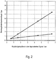
- Fig. 2 illustrates that in most cases a "fixed” load-dependent brake control is implemented for all axles on trailers. “Permanently set” means that, depending on the driver's braking request and depending on the currently measured load condition (X-axis), a defined brake cylinder pressure that is fixed or unchangeable for these respective specifications is set. The pressure sensor 15 then supplies a constant signal for the braking request. Dynamic changes to this transmission ratio, depending on changing status or input variables, are usually not possible.
- the brake request signal must be converted into a corresponding deceleration signal or a corresponding braking force depending on the respective driving state, in particular the mass of the vehicle.
- the current driving state of the vehicle can be approximated using a large number of variables, such as B. Vehicle speed, wheel speeds, wheel slips, vehicle mass, steering angle, road inclination, current gear ratio, cooling system temperature, battery charge status, etc.
- the energy input into the brake linings during braking is calculated by the electronic control device (eg trailer EBS) or by its evaluation device and accumulated or added up.
- the energy input of the brake pads is for example, on the brake cylinder pressure and on the vehicle speed (wheel speed) or the distance covered during braking).
- the limit value can be parameterized depending on the brake lining material used
- the brake pressure or the associated energy input for a current brake application and / or for one or more future brake applications is defined - for example within the permitted framework of ECE R13 - via the speed required to achieve the required brake pedal actuation and possibly other parameters such as the load required braking effect necessary value increased.
- This can be done, for example, by modulating a brake cylinder pressure that is higher than would be required per se as a result of the current parameters for braking, that is, for example, higher than that actually after Fig. 2 Brake cylinder (chamber) pressure to be set.
- the brake cylinder pressure required per se is that which would be set with the evaluation and control device in view of the parameters present in each case without considering the brake energy consideration.
- the increased brake pressure leads to an increased energy input. Disadvantageous changes in the brake lining coefficient of friction can thus be reduced or even completely avoided.
- the temporarily controlled increase in brake cylinder pressure and thus a temperature increase in the brake lining ensures that the coefficient of friction remains in the normal range or is even returned to it.
Description
Die Erfindung betrifft ein Verfahren zur Ansteuerung einer oder mehrerer Bremsen, insbesondere Scheibenbremsen, eines Bremssystems für ein Fahrzeug, insbesondere für ein Anhängerfahrzeug.The invention relates to a method for controlling one or more brakes, in particular disc brakes, of a brake system for a vehicle, in particular for a trailer vehicle.
Die Bremsbeläge 6a, 6b werden bei Bremsungen jeweils gegen hier nicht dargestellte Bremsscheiben der Scheibenbremsen 1 - 4 gepresst, um das Fahrzeug abzubremsen. Infolge der Bremsungen verschleißen die Bremsbeläge 6a, 6b und die Bremsscheibe. Um den Verschleiß der Bremsbeläge 6a, 6b und der Bremsscheibe als Summensignal zu ermitteln, ist es bekannt, Verschleißsensoren 7 an den hier vier (oder mehr) Scheibenbremsen 1 - 4 jeweils über eine Verbindung wie Kabel 8 oder drahtlos an eine Auswertungs- und Steuerungseinrichtung 9 anzuschließen. Diese kann - bei dem Stand der Technik und auch bei der Erfindung - als Teil eines übergeordneten, hier nicht weiter dargestellten - Fahrzeugzustandsermittlungs- und -informationssystems des Fahrzeugs ausgelegt sein.When the brakes are applied, the
Nach dem in
Aus der
Die Bremsenergie wird nach der ![]()
- WB := Bremsenergie;
- MB := Bremsmoment;
- ϕB := Raddrehwinkel.
- W B : = braking energy;
- M B : = braking torque;
- ϕ B : = wheel rotation angle.
Der Raddrehwinkel wird vorzugsweise unmittelbar über einen z.B. für eine ABS- und/oder EBS-Funktion eines Bremssystems zur Bremsregelung sowieso benötigten und daher bereitstehenden Drehzahlsensor bestimmt. Der Drehzahlsensor besteht aus einem Polrad, welches mit der Radnabe umläuft und einem feststehenden Geber, der die vorbei bewegten Zähne, Magnetspulen usw. des Polrades mit einem Spannungsimpuls registriert. Bei z.B. 100 Zähnen pro Polrad entspricht somit ein Impuls einem Raddrehwinkel von 3,6°. Durch Aufsummieren dieser Impulse wird von der Auswertungseinrichtung der Raddrehwinkel während der Bremsphase ermittelt.The angle of rotation of the wheel is preferably determined directly via a speed sensor that is required, for example, for an ABS and / or EBS function of a brake system for brake control and is therefore available. The speed sensor consists of a pole wheel, which rotates with the wheel hub and a stationary encoder, which registers the moving teeth, magnetic coils, etc. of the pole wheel with a voltage pulse. With 100 teeth per pole wheel, for example, one pulse corresponds to a wheel rotation angle of 3.6 °. By adding up these pulses, the evaluation device determines the wheel rotation angle during the braking phase.
Das Bremsmoment wird vorzugsweise mittels des in einem ABS-/EBS-System vorhandenen Drucksensors mit der Auswertungseinrichtung durch Ermittlung des Bremszylinderdruckes nach folgender Formel berechnet: ![]()
- PZ = Druck im Bremszylinder und
- PAn = Anlegedruck der Bremse
- i = Kraftübersetzungsverhältnis der Bremse
- ε = mechanischer Wirkungsgrad des Kraftübersetzungsmechanismus der Bremse
- C* = Bremsenkennwert ≈ 2 x µB
- µB = Reibungswert des Bremsbelages
- reff = wirksamer Reibradius der Bremsscheibe
- Z = Anzahl der aufsummierten Drehwinkelimpulse eines ABS-Polrades
- AZ = wirksame Kolbenfläche des Bremszylinder.
- P Z = pressure in the brake cylinder and
- P An = brake application pressure
- i = power transmission ratio of the brake
- ε = mechanical efficiency of the force transmission mechanism of the brake
- C * = brake parameter ≈ 2 x µ B
- µ B = friction coefficient of the brake lining
- r eff = effective friction radius of the brake disc
- Z = number of the cumulative angle of rotation pulses of an ABS pole wheel
- A Z = effective piston area of the brake cylinder.
Zudem kann die pro Drehung entsprechend einem Zahn eines ABS-Polrades, also die pro Drehzahlimpuls, umgesetzte Bremsenergie wie folgt ermittelt werden ![]()
- K
- = AZ i ε C* reff 2π/n;
- PZ
- = Druck im Bremszylinder und
- PAn
- = Anlegedruck der Bremse
- K
- = A Z i ε C * r eff 2π / n;
- PZ
- = Pressure in the brake cylinder and
- PAn
- = Brake application pressure
Die umgesetzte Bremsenergie wird somit durch einfache Verknüpfungen des Bremszylinderdruck-Signales mit der Anzahl der Raddrehimpulse ermittelt.The converted braking energy is thus determined by simply combining the brake cylinder pressure signal with the number of wheel rotation pulses.
Die angegebenen Formeln sind beispielhaft und müssen nicht zwingend für die Ermittlung der Bremsenergie verwendet werden. Sie eignen sich insbesondere für Scheibenbremsen mit elektromotorischer oder pneumatischer Betätigung sowie mit einem Schwimm-, Fest- oder Schiebesattel. Vorzugsweise umfasst das Nachstellsystem auf beiden Seiten der Bremsscheibe jeweils wenigstens eine der elektromotorischen Nachstelleinrichtungen.The formulas given are examples and do not necessarily have to be used to determine the braking energy. They are particularly suitable for disc brakes with electromotive or pneumatic actuation and with a floating, fixed or sliding caliper. The adjustment system preferably comprises at least one of the electromotive adjustment devices on both sides of the brake disc.
In der vorstehend beschriebenen
Aus der
Bei Anhängerfahrzeugen wird der Bremszylinderdruck bei Bremsungen in der Regel aus einer Bremspedalinformation und einer Beladungsinformation ermittelt und eingestellt, um eine gewünschte Abbremsung zu erzielen. Die Abbremsung ist der Quotient aus der Bremskraft und der Gewichtskraft des Fahrzeugs.In the case of trailer vehicles, the brake cylinder pressure during braking is usually determined from brake pedal information and loading information and adjusted in order to achieve the desired braking. The deceleration is the quotient of the braking force and the weight of the vehicle.
Werden über eine oder mehrere Bremsungen hinweg nur relativ niedrige Bremsdrücke aufgebaut oder wird nur selten bzw. wenig gebremst, kann dies zu einer nachteilige Beeinflussung des Reibwertes der Bremsbeläge führen.If only relatively low brake pressures are built up over one or more braking operations, or if braking is carried out only rarely or very little, this can have an adverse effect on the coefficient of friction of the brake linings.
Vor diesem Hintergrund ist es die Aufgabe der Erfindung, ein einfaches Verfahren zu schaffen, mit dem nachteiligen Entwicklungen des Reibwertes der Bremsbeläge eines Fahrzeugbremssystems, insbesondere eines Anhängerfahrzeugbremssystems, frühzeitig entgegengesteuert werden kann.Against this background, the object of the invention is to create a simple method with which disadvantageous developments in the coefficient of friction of the brake linings of a vehicle brake system, in particular a trailer vehicle brake system, can be counteracted at an early stage.
Die Erfindung erreicht dieses Ziel durch den Gegenstand des Anspruchs 1.The invention achieves this aim by the subject matter of
Geschaffen wird ein Verfahren zur Ansteuerung einer oder mehrerer Bremsen, insbesondere Scheibenbremsen, eines Bremssystems eines Fahrzeugs, insbesondere eines Anhängerfahrzeugs, mit zumindest folgenden Schritten:
- a) Bereitstellen des Fahrzeugs mit dem Bremssystem mit wenigstens einer oder mehreren Bremsen mit Bremsbelägen, die eine Belagträgerplatte und einen Reibbelag aufweisen, und wenigstens einer Auswertungs- und Steuerungseinrichtung;
- b) Ermitteln der bei einer oder mehreren Bremsungen umgesetzten Bremsenergie je Bremse mit der Auswertungs- und Steuerungseinrichtung;
- c) Vergleich der ermittelten Bremsenergie mit einem oder mehreren vorzugweise vorgegebenen Sollwerten mit der Auswertungs- und Steuerungseinrichtung; und
- d) Erhöhung des Energieeintrags bei einer aktuellen und/oder einer oder mehreren folgenden Bremsungen mit der Auswertungs- und Steuerungseinrichtung, wenn die ermittelte Bremsenergie den Sollwert unterschreitet.
- a) providing the vehicle with the brake system with at least one or more brakes with brake linings which have a lining carrier plate and a friction lining, and at least one evaluation and control device;
- b) Determination of the braking energy converted during one or more braking operations per brake with the evaluation and control device;
- c) comparison of the determined braking energy with one or more preferably predetermined setpoint values with the evaluation and control device; and
- d) Increase in the energy input during a current and / or one or more subsequent braking operations with the evaluation and control device if the braking energy determined falls below the setpoint value.
Vorteilhafte Ausgestaltungen dieses Verfahrens sind den Unteransprüchen zu entnehmen.Advantageous embodiments of this method can be found in the subclaims.
Wird ein zu geringer Energieeintrag über eine vorgegebene Einsatzzeit und/oder eine vorgegebene Kilometerlaufleistung, z.B. 20.000 km) detektiert (der Energiegrenzwert kann abhängig vom eingesetzten Bremsbelagmaterial parametriert werden) ist vorhersehbar, dass sich der Bremsbelagreibwert verschlechtern wird. Um dieser drohenden Verschlechterung entgegenzusteuern, wird definiert - beispielsweise im erlaubten Rahmen der ECE R13 - der Energieeintrag bei einer aktuellen Bremsung und/oder bei einer oder mehreren zukünftigen Bremsungen angehoben. Dies kann beispielsweise durch ein Aussteuern eines Bremszylinderdruckes erfolgen, der höher ist, als er an sich infolge aktueller bzw. jeweils zukünftiger Parameter - wie Charakteristik der Bremspedalbetätigung, Geschwindigkeit und ggf. Beladungszustand des Fahrzeugs - ohne eine Berücksichtigung der Bremsenergiebetrachtung eingestellt würde oder mindestens erforderlich wäre. Dies führt bei diesen Bremsungen zu einem höheren Energieeintrag und höheren Temperaturen an den Bremsbelägen. Nachteilige Veränderungen des Bremsbelagreibwertes können damit verringert oder sogar vollständig vermieden werden.If insufficient energy input is detected over a specified operating time and / or a specified mileage, e.g. 20,000 km) (the energy limit value can be parameterized depending on the brake lining material used), it is foreseeable that the brake lining coefficient of friction will worsen. In order to counteract this impending deterioration, the energy input for a current braking and / or for one or more future braking operations is defined - for example within the permitted framework of ECE R13. This can be done, for example, by modulating a brake cylinder pressure that is higher than would be set or would be at least required as a result of current or future parameters - such as the characteristics of the brake pedal actuation, speed and possibly the load status of the vehicle - without considering the braking energy consideration . During these braking operations, this leads to a higher energy input and higher temperatures on the brake linings. Disadvantageous changes in the brake lining coefficient of friction can thus be reduced or even completely avoided.
Bevorzugt werden als die eingesetzten Bremsen Scheibenbremsen, insbesondere druckluftbetätigte Scheibenbremsen verwendet. Die Erfindung ist aber prinzipiell auch für Trommelbremsen geeignet.Disc brakes, in particular compressed air-actuated disc brakes, are preferably used as the brakes used. In principle, however, the invention is also suitable for drum brakes.
Der Energieeintrag kann beispielsweise - dies ist aber nicht zwingend - mit dem in der
Vorzugsweise und einfach wird im Schritt d) der Energieeintrag bei der aktuellen Bremsung und/oder bei einer oder mehreren zukünftigen Bremsungen dadurch angehoben, dass ein Bremszylinderdruck eingestellt wird, der höher ist, als er an sich infolge aktueller bzw. zukünftiger Parameter wie einer Bremspedalbetätigung, einer Fahrzeuggeschwindigkeit und einem Beladungszustand des Fahrzeugs für die jeweilige Bremsung mindestens erforderlich wäre.In step d), the energy input during the current braking operation and / or during one or more future braking operations is preferably and simply increased by setting a brake cylinder pressure that is higher than it is due to the current braking operation or future parameters such as a brake pedal actuation, a vehicle speed and a load condition of the vehicle would be at least required for the respective braking.
Dabei ist es zur Optimierung der Reibwerteigenschaften der Bremsbeläge vorteilhaft, wenn im Schritt d) der Energieeintrag bei der aktuellen Bremsung und/oder bei einer oder mehreren zukünftigen Bremsungen so angehoben wird, dass an den Bremsbelägen der Bremsen eine Temperatur von mindestens 150° C oder mehr erreicht wird.To optimize the friction properties of the brake linings, it is advantageous if in step d) the energy input during the current braking and / or during one or more future braking operations is increased so that a temperature of at least 150 ° C or more on the brake linings of the brakes is achieved.
Nachfolgend wird die Erfindung unter Bezug auf die Zeichnung anhand von Ausführungsbeispielen näher beschrieben. Es zeigen:
- Fig.1a
- eine stark schematisierte und vereinfachte Darstellung eines ersten bekannten Fahrzeugbremssystems;
- Fig.1b
- eine stark schematisierte und vereinfachte Darstellung eines weiteren Fahrzeugbremssystems;
- Fig. 2
- ein Diagramm, welches Bremsdruckverläufe an einem Anhängerfahrzeug veranschaulicht.
- Fig.1a
- a highly schematic and simplified representation of a first known vehicle brake system;
- Fig.1b
- a highly schematic and simplified representation of a further vehicle braking system;
- Fig. 2
- a diagram which illustrates brake pressure curves on a trailer vehicle.
Wie nach dem Stand der Technik der
Denn insbesondere wird mit dem erfindungsgemäßen Verfahren bei einem Bremssystem, beispielsweise nach Art der
Wenn der Fahrer über die Stellung des Bremspedales eine bestimmte Verzögerung vorgibt (Fahrerwunsch), so muss das Bremsanforderungssignal in Abhängigkeit vom jeweiligen Fahrzustand, insbesondere der Masse des Fahrzeuges in ein entsprechendes Verzögerungssignal bzw. eine entsprechende Bremskraft umgewandelt werden. Der aktuelle Fahrzustand des Fahrzeuges ist durch eine Vielzahl von Variablen näherungsweise abbildbar, wie z. B. Fahrzeuggeschwindigkeit, Raddrehzahlen, Radschlüpfe, Fahrzeugmasse, Lenkwinkel, Fahrbahnneigung, momentane Getriebeübersetzung, Kühlsystemtemperatur, Batterieladezustand etc.If the driver specifies a certain deceleration via the position of the brake pedal (driver request), the brake request signal must be converted into a corresponding deceleration signal or a corresponding braking force depending on the respective driving state, in particular the mass of the vehicle. The current driving state of the vehicle can be approximated using a large number of variables, such as B. Vehicle speed, wheel speeds, wheel slips, vehicle mass, steering angle, road inclination, current gear ratio, cooling system temperature, battery charge status, etc.
Der Bremszylinderdruck bei Bremsungen wird bei Anhängern vorzugsweise wie folgt von der Auswertungs- und Steuerungseinrichtung des Bremssystems berechnet:
Bremszylinderdruck = f [Fahrerwunsch (coupling head pressure), Beladungszustand].In the case of trailers, the brake cylinder pressure during braking is preferably calculated by the evaluation and control device of the brake system as follows:
Brake cylinder pressure = f [driver's request (coupling head pressure), load status].
Um eine negative Entwicklung der Reibwerte der Bremsbeläge infolge eines zu niedrigen Energieeintrags zu vermeiden, wird die nachfolgend beschriebene Verfahrensweise implementiert:
Bremsbeläge, bei denen sich im Laufe der Zeit der Reibwert aufgrund von zu wenigen Bremsungen oder von Bremsungen mit einem niedrigen Bremszylinderdruck, also durch zu geringen Energieeintrag, z.B. hervorgerufen durch häufigen Retardereinsatz, reduziert, erreichen nicht oder nicht genügend lange die notwendige Temperatur von beispielsweise mehr als 150° C, welche jedenfalls zeitweise erforderlich ist, um den jeweiligen Bremsbelagreibwert der Bremsbeläge im Bereich einer Normcharakteristik zu halten. Der Bremsbelagreibwert kann sich daher zunehmend verschlechtern.In order to avoid a negative development of the friction values of the brake linings as a result of too low an energy input, the procedure described below is implemented:
Brake pads in which the coefficient of friction is reduced over time due to insufficient braking or braking with a low brake cylinder pressure, i.e. due to insufficient energy input, e.g. caused by frequent use of retarders, do not reach the required temperature of, for example, more than enough than 150 ° C, which is required at times in order to keep the respective brake lining coefficient of friction of the brake linings in the range of a standard characteristic. The brake lining coefficient of friction can therefore deteriorate increasingly.
Eine derartige nachteilige Entwicklung lässt sich frühzeitig vorhersagen und/oder erkennen.Such a disadvantageous development can be predicted and / or recognized at an early stage.
Dazu wird der Energieeintrag in die Bremsbeläge bei Bremsungen mit der elektronischen Steuereinrichtung (z.B. Trailer-EBS) bzw. von deren Auswertungseinrichtung errechnet und aufkummuliert bzw. aufsummiert. Der Energieeintrag der Bremsbeläge ist beispielsweise von dem Bremszylinderdruck und von der Fahrzeuggeschwindigkeit (Radgeschwindigkeit) bzw. der bei der Bremsung zurückgelegten Fahrtstrecke abhängig).For this purpose, the energy input into the brake linings during braking is calculated by the electronic control device (eg trailer EBS) or by its evaluation device and accumulated or added up. The energy input of the brake pads is for example, on the brake cylinder pressure and on the vehicle speed (wheel speed) or the distance covered during braking).
Wird nun über den aufsummierten Energieeintrag ein relativ zu einem vorgespeicherten Grenzwert zu geringer Energieeintrag über die Einsatzzeit (und/oder die zurückgelegte Fahrtstrecke) detektiert (der Grenzwert kann abhängig vom eingesetzten Bremsbelagmaterial parametriert werden) ist vorhersehbar, dass sich der Bremsbelagreibwert verschlechtern wird.If an energy input that is too low relative to a pre-stored limit value over the operating time (and / or the distance traveled) is detected via the accumulated energy input (the limit value can be parameterized depending on the brake lining material used), it can be foreseen that the brake lining coefficient of friction will worsen.
Um dieser drohenden Verschlechterung entgegenzusteuern, wird definiert - beispielsweise im erlaubten Rahmen der ECE R13 - der Bremsdruck bzw. damit verbunden der Energieeintrag bei einer aktuellen Bremsung und/oder bei einer oder mehreren zukünftigen Bremsungen über den an sich zum Erreichen der gemäß Bremspedalbetätigung, der Geschwindigkeit und ggf. weiterer Parameter wie der Beladung erforderlichen Bremswirkung notwendigen Wert angehoben. Dies kann beispielsweise durch ein Aussteuern eines Bremszylinderdruckes erfolgen, der höher ist, als er an sich infolge der aktuellen Parameter für die Bremsung erforderlich wäre, also beispielsweise höher als der eigentlich nach
Der erhöhte Bremsdruck führt zu einem erhöhten Energieeintrag. Nachteilige Veränderungen des Bremsbelagreibwertes können damit verringert oder sogar vollständig vermieden werden.The increased brake pressure leads to an increased energy input. Disadvantageous changes in the brake lining coefficient of friction can thus be reduced or even completely avoided.
Durch die zeitweise gesteuerte Bremzylinderdruckerhöhung und somit durch eine Temperaturanhebung des Bremsbelags wird sichergestellt, dass der Reibwert im Normbereich bleibt oder sogar in diesen zurückgeführt wird.The temporarily controlled increase in brake cylinder pressure and thus a temperature increase in the brake lining ensures that the coefficient of friction remains in the normal range or is even returned to it.
- 11
- ScheibenbremseDisc brake
- 22
- ScheibenbremseDisc brake
- 33
- ScheibenbremseDisc brake
- 44th
- ScheibenbremseDisc brake
- 5a, b5a, b
- Achsenaxes
- 6a, b6a, b
- BremsbelagBrake pad
- 77th
- VerschleißsensorenWear sensors
- 88th
- Kabelelectric wire
- 99
- AuswertungseinrichtungEvaluation facility
- 1414th
- PolradsensorenPole wheel sensors
- 1515th
- DrucksensorPressure sensor
Claims (7)
- A method for controlling one or more brakes, in particular disc brakes, of a brake system of a vehicle, in particular a trailer vehicle, comprising at least the following steps:a) providing the vehicle having the brake system with at least one or more brakes with brake pads (6a, 6b) that have a pad carrier plate and a friction lining, and with at least one evaluation and control device (9);b) determining the braking energy per brake converted during one or more brake applications by means of the evaluation and control device (9);c) comparing the braking energy determined with at least one setpoint value by means of the evaluation and control device (9); characterised in that the method also comprises the following step:d) increasing the energy input during a current and/or one or more subsequent brake applications by means of the evaluation and control device (9) when the braking energy determined falls below the setpoint value.
- A method according to claim 1, characterised in that at step b) the braking energy converted during the plurality of brake applications is totalled and that at step c) a total braking energy value determined for the plurality of brake applications is compared with one or more predetermined setpoint values and that at step d) the brake cylinder pressure is increased during one or more subsequent brake applications if the total braking energy falls below the relevant predetermined setpoint value.
- A method according to claim 1 or 2, characterised in that at step d) a gradient of a curve, in particular of a straight line, is determined that reflects the total braking energy as a function of the kilometrage and that the setpoint value is a gradient setpoint value over a predetermined kilometrage interval.
- A method according to any one of the previous claims, characterised in that at step d) a brake cylinder pressure at brake cylinders of the brakes is raised in order to increase the energy input.
- A method according to any one of the previous claims, characterised in that at step d) the energy input during the current brake application and/or during one or more future brake applications is increased by setting a brake cylinder pressure that is greater than is inherently necessary due to current or future parameters such as brake pedal actuation, vehicle speed and loading state of the vehicle for the relevant brake application.
- A method according to any one of the previous claims, characterised in that at step d) the energy input during the current brake application and/or during one or more future brake applications is raised so as to achieve a temperature of at least 150°C or more at the brake pads of the brakes.
- A method according to any one of the previous claims, characterised in that disc brakes are used as the brakes.
Applications Claiming Priority (1)
| Application Number | Priority Date | Filing Date | Title |
|---|---|---|---|
| DE102015112363.0A DE102015112363A1 (en) | 2015-07-29 | 2015-07-29 | Method for controlling one or more brakes of a vehicle |
Publications (3)
| Publication Number | Publication Date |
|---|---|
| EP3124342A2 EP3124342A2 (en) | 2017-02-01 |
| EP3124342A3 EP3124342A3 (en) | 2017-05-10 |
| EP3124342B1 true EP3124342B1 (en) | 2021-06-02 |
Family
ID=56555251
Family Applications (1)
| Application Number | Title | Priority Date | Filing Date |
|---|---|---|---|
| EP16181579.0A Active EP3124342B1 (en) | 2015-07-29 | 2016-07-28 | Method for controlling one or more brakes of a vehicle |
Country Status (2)
| Country | Link |
|---|---|
| EP (1) | EP3124342B1 (en) |
| DE (1) | DE102015112363A1 (en) |
Families Citing this family (2)
| Publication number | Priority date | Publication date | Assignee | Title |
|---|---|---|---|---|
| US20190135257A1 (en) * | 2017-11-03 | 2019-05-09 | GM Global Technology Operations LLC | Methods and systems to adaptively monitor brake pad wear |
| DE102018120477A1 (en) * | 2018-08-22 | 2020-02-27 | Wabco Gmbh | Electronic braking system |
Family Cites Families (5)
| Publication number | Priority date | Publication date | Assignee | Title |
|---|---|---|---|---|
| DE4230675A1 (en) | 1992-09-14 | 1994-03-17 | Knorr Bremse Ag | Vehicle with a vehicle computer for measurement signals from a wheel area |
| FR2781443B1 (en) | 1998-07-21 | 2000-09-15 | Sommer Ind | DEVICE FOR PROTECTING THE LOWER LIMBS OF AN OCCUPANT BEFORE A MOTOR VEHICLE |
| DE19933961B4 (en) | 1999-07-20 | 2008-04-24 | Knorr-Bremse Systeme für Nutzfahrzeuge GmbH | Method and device for monitoring the functional state of braking devices of vehicles and / or vehicle trailers |
| DE10150047A1 (en) | 2001-10-10 | 2003-06-26 | Knorr Bremse Systeme | Control method for disc brakes |
| DE502005010767D1 (en) * | 2004-09-24 | 2011-02-10 | Continental Teves Ag & Co Ohg | METHOD AND DEVICE FOR SUPPORTING A BRAKE SYSTEM WITH REDUCED EFFICIENCY |
-
2015
- 2015-07-29 DE DE102015112363.0A patent/DE102015112363A1/en active Pending
-
2016
- 2016-07-28 EP EP16181579.0A patent/EP3124342B1/en active Active
Non-Patent Citations (1)
| Title |
|---|
| None * |
Also Published As
| Publication number | Publication date |
|---|---|
| EP3124342A3 (en) | 2017-05-10 |
| EP3124342A2 (en) | 2017-02-01 |
| DE102015112363A1 (en) | 2017-02-02 |
Similar Documents
| Publication | Publication Date | Title |
|---|---|---|
| EP1436521B1 (en) | Control method for adjusting a disk brake | |
| EP2630013B1 (en) | Method for controlling an antislip-regulated friction brake system of a rail vehicle | |
| EP1979645B1 (en) | Method for indicating wear of a brake lining in a disk brake with an electric motor actuator | |
| DE102010043320A1 (en) | Apparatus and method for determining a measure of an effective braking force or friction force on a disc brake | |
| DE3502050A1 (en) | DEVICE FOR MEASURING AND / OR REGULATING A BRAKE FORCE AND / OR A BRAKE TORQUE | |
| DE3502052A1 (en) | DEVICE FOR MEASURING AND / OR CONTROLLING THE WEAR OF A COMPONENT | |
| EP3802244B1 (en) | Control unit and method for controlling a brake actuator of a vehicle, particularly of a railway vehicle | |
| WO2008037347A1 (en) | Braking system and method for braking a vehicle with a hybrid drive | |
| DE102008015873A1 (en) | Vehicle, in particular rail vehicle, with a device for monitoring the braking effect | |
| EP3642086B1 (en) | Method for determining the overall utility vehicle deceleration values which can be achieved by actuating wheel brakes, brake system for carrying out the method, and utility vehicle comprising same | |
| DE102014107402B4 (en) | Rail vehicle braking system with a conditioning device, conditioning device and method for operating a conditioning device | |
| EP3625094B1 (en) | Method for estimating the achievable total braking forces for the automated deceleration of a utility vehicle, braking system and utility vehicle having said braking system | |
| EP3328702B1 (en) | Method and system for analysing the wear behaviour of brake linings | |
| DE102015113587A1 (en) | Linear sensor for a brake | |
| EP3124342B1 (en) | Method for controlling one or more brakes of a vehicle | |
| EP2123528B1 (en) | Vehicle combination with an anti jack-knife trailer brake device | |
| WO2000025036A1 (en) | Method and device for monitoring the movements of an actuator | |
| DE10235472A1 (en) | Device for controlling the brakes of a commercial vehicle | |
| DE102011120791A1 (en) | Method for performing a brake regeneration | |
| DE19910048A1 (en) | Method and device for monitoring the movement of an actuator | |
| DE102021104800A1 (en) | Method for determining an optimal or maximum permissible speed of a rail vehicle | |
| DE10257839B4 (en) | Monitoring of wheel brakes | |
| EP1572513A1 (en) | Brake system and method for operating a brake system for electrically driven vehicles | |
| DE102009016986A1 (en) | Method and device for braking force control | |
| DE10197123B4 (en) | Method and system for braking commercial vehicles |
Legal Events
| Date | Code | Title | Description |
|---|---|---|---|
| PUAI | Public reference made under article 153(3) epc to a published international application that has entered the european phase |
Free format text: ORIGINAL CODE: 0009012 |
|
| STAA | Information on the status of an ep patent application or granted ep patent |
Free format text: STATUS: THE APPLICATION HAS BEEN PUBLISHED |
|
| AK | Designated contracting states |
Kind code of ref document: A2 Designated state(s): AL AT BE BG CH CY CZ DE DK EE ES FI FR GB GR HR HU IE IS IT LI LT LU LV MC MK MT NL NO PL PT RO RS SE SI SK SM TR |
|
| AX | Request for extension of the european patent |
Extension state: BA ME |
|
| PUAL | Search report despatched |
Free format text: ORIGINAL CODE: 0009013 |
|
| AK | Designated contracting states |
Kind code of ref document: A3 Designated state(s): AL AT BE BG CH CY CZ DE DK EE ES FI FR GB GR HR HU IE IS IT LI LT LU LV MC MK MT NL NO PL PT RO RS SE SI SK SM TR |
|
| AX | Request for extension of the european patent |
Extension state: BA ME |
|
| RIC1 | Information provided on ipc code assigned before grant |
Ipc: B60T 8/172 20060101ALI20170403BHEP Ipc: B60T 17/22 20060101ALI20170403BHEP Ipc: B60T 8/17 20060101AFI20170403BHEP |
|
| STAA | Information on the status of an ep patent application or granted ep patent |
Free format text: STATUS: REQUEST FOR EXAMINATION WAS MADE |
|
| 17P | Request for examination filed |
Effective date: 20171110 |
|
| RBV | Designated contracting states (corrected) |
Designated state(s): AL AT BE BG CH CY CZ DE DK EE ES FI FR GB GR HR HU IE IS IT LI LT LU LV MC MK MT NL NO PL PT RO RS SE SI SK SM TR |
|
| RIC1 | Information provided on ipc code assigned before grant |
Ipc: B60T 17/22 20060101ALI20201014BHEP Ipc: B60T 8/172 20060101ALI20201014BHEP Ipc: B60T 8/17 20060101AFI20201014BHEP |
|
| GRAP | Despatch of communication of intention to grant a patent |
Free format text: ORIGINAL CODE: EPIDOSNIGR1 |
|
| STAA | Information on the status of an ep patent application or granted ep patent |
Free format text: STATUS: GRANT OF PATENT IS INTENDED |
|
| INTG | Intention to grant announced |
Effective date: 20201215 |
|
| GRAS | Grant fee paid |
Free format text: ORIGINAL CODE: EPIDOSNIGR3 |
|
| GRAA | (expected) grant |
Free format text: ORIGINAL CODE: 0009210 |
|
| STAA | Information on the status of an ep patent application or granted ep patent |
Free format text: STATUS: THE PATENT HAS BEEN GRANTED |
|
| REG | Reference to a national code |
Ref country code: CH Ref legal event code: EP |
|
| AK | Designated contracting states |
Kind code of ref document: B1 Designated state(s): AL AT BE BG CH CY CZ DE DK EE ES FI FR GB GR HR HU IE IS IT LI LT LU LV MC MK MT NL NO PL PT RO RS SE SI SK SM TR |
|
| REG | Reference to a national code |
Ref country code: GB Ref legal event code: FG4D Free format text: NOT ENGLISH |
|
| REG | Reference to a national code |
Ref country code: AT Ref legal event code: REF Ref document number: 1398179 Country of ref document: AT Kind code of ref document: T Effective date: 20210615 |
|
| REG | Reference to a national code |
Ref country code: IE Ref legal event code: FG4D Free format text: LANGUAGE OF EP DOCUMENT: GERMAN |
|
| REG | Reference to a national code |
Ref country code: DE Ref legal event code: R096 Ref document number: 502016013127 Country of ref document: DE |
|
| REG | Reference to a national code |
Ref country code: SE Ref legal event code: TRGR |
|
| REG | Reference to a national code |
Ref country code: LT Ref legal event code: MG9D |
|
| PG25 | Lapsed in a contracting state [announced via postgrant information from national office to epo] |
Ref country code: FI Free format text: LAPSE BECAUSE OF FAILURE TO SUBMIT A TRANSLATION OF THE DESCRIPTION OR TO PAY THE FEE WITHIN THE PRESCRIBED TIME-LIMIT Effective date: 20210602 Ref country code: LT Free format text: LAPSE BECAUSE OF FAILURE TO SUBMIT A TRANSLATION OF THE DESCRIPTION OR TO PAY THE FEE WITHIN THE PRESCRIBED TIME-LIMIT Effective date: 20210602 Ref country code: BG Free format text: LAPSE BECAUSE OF FAILURE TO SUBMIT A TRANSLATION OF THE DESCRIPTION OR TO PAY THE FEE WITHIN THE PRESCRIBED TIME-LIMIT Effective date: 20210902 Ref country code: HR Free format text: LAPSE BECAUSE OF FAILURE TO SUBMIT A TRANSLATION OF THE DESCRIPTION OR TO PAY THE FEE WITHIN THE PRESCRIBED TIME-LIMIT Effective date: 20210602 |
|
| REG | Reference to a national code |
Ref country code: NL Ref legal event code: MP Effective date: 20210602 |
|
| PG25 | Lapsed in a contracting state [announced via postgrant information from national office to epo] |
Ref country code: PL Free format text: LAPSE BECAUSE OF FAILURE TO SUBMIT A TRANSLATION OF THE DESCRIPTION OR TO PAY THE FEE WITHIN THE PRESCRIBED TIME-LIMIT Effective date: 20210602 Ref country code: NO Free format text: LAPSE BECAUSE OF FAILURE TO SUBMIT A TRANSLATION OF THE DESCRIPTION OR TO PAY THE FEE WITHIN THE PRESCRIBED TIME-LIMIT Effective date: 20210902 Ref country code: RS Free format text: LAPSE BECAUSE OF FAILURE TO SUBMIT A TRANSLATION OF THE DESCRIPTION OR TO PAY THE FEE WITHIN THE PRESCRIBED TIME-LIMIT Effective date: 20210602 Ref country code: GR Free format text: LAPSE BECAUSE OF FAILURE TO SUBMIT A TRANSLATION OF THE DESCRIPTION OR TO PAY THE FEE WITHIN THE PRESCRIBED TIME-LIMIT Effective date: 20210903 Ref country code: LV Free format text: LAPSE BECAUSE OF FAILURE TO SUBMIT A TRANSLATION OF THE DESCRIPTION OR TO PAY THE FEE WITHIN THE PRESCRIBED TIME-LIMIT Effective date: 20210602 |
|
| PG25 | Lapsed in a contracting state [announced via postgrant information from national office to epo] |
Ref country code: ES Free format text: LAPSE BECAUSE OF FAILURE TO SUBMIT A TRANSLATION OF THE DESCRIPTION OR TO PAY THE FEE WITHIN THE PRESCRIBED TIME-LIMIT Effective date: 20210602 Ref country code: RO Free format text: LAPSE BECAUSE OF FAILURE TO SUBMIT A TRANSLATION OF THE DESCRIPTION OR TO PAY THE FEE WITHIN THE PRESCRIBED TIME-LIMIT Effective date: 20210602 Ref country code: PT Free format text: LAPSE BECAUSE OF FAILURE TO SUBMIT A TRANSLATION OF THE DESCRIPTION OR TO PAY THE FEE WITHIN THE PRESCRIBED TIME-LIMIT Effective date: 20211004 Ref country code: NL Free format text: LAPSE BECAUSE OF FAILURE TO SUBMIT A TRANSLATION OF THE DESCRIPTION OR TO PAY THE FEE WITHIN THE PRESCRIBED TIME-LIMIT Effective date: 20210602 Ref country code: CZ Free format text: LAPSE BECAUSE OF FAILURE TO SUBMIT A TRANSLATION OF THE DESCRIPTION OR TO PAY THE FEE WITHIN THE PRESCRIBED TIME-LIMIT Effective date: 20210602 Ref country code: EE Free format text: LAPSE BECAUSE OF FAILURE TO SUBMIT A TRANSLATION OF THE DESCRIPTION OR TO PAY THE FEE WITHIN THE PRESCRIBED TIME-LIMIT Effective date: 20210602 Ref country code: SK Free format text: LAPSE BECAUSE OF FAILURE TO SUBMIT A TRANSLATION OF THE DESCRIPTION OR TO PAY THE FEE WITHIN THE PRESCRIBED TIME-LIMIT Effective date: 20210602 Ref country code: SM Free format text: LAPSE BECAUSE OF FAILURE TO SUBMIT A TRANSLATION OF THE DESCRIPTION OR TO PAY THE FEE WITHIN THE PRESCRIBED TIME-LIMIT Effective date: 20210602 |
|
| REG | Reference to a national code |
Ref country code: CH Ref legal event code: PL |
|
| REG | Reference to a national code |
Ref country code: DE Ref legal event code: R097 Ref document number: 502016013127 Country of ref document: DE |
|
| PG25 | Lapsed in a contracting state [announced via postgrant information from national office to epo] |
Ref country code: MC Free format text: LAPSE BECAUSE OF FAILURE TO SUBMIT A TRANSLATION OF THE DESCRIPTION OR TO PAY THE FEE WITHIN THE PRESCRIBED TIME-LIMIT Effective date: 20210602 |
|
| REG | Reference to a national code |
Ref country code: BE Ref legal event code: MM Effective date: 20210731 |
|
| PLBE | No opposition filed within time limit |
Free format text: ORIGINAL CODE: 0009261 |
|
| STAA | Information on the status of an ep patent application or granted ep patent |
Free format text: STATUS: NO OPPOSITION FILED WITHIN TIME LIMIT |
|
| PG25 | Lapsed in a contracting state [announced via postgrant information from national office to epo] |
Ref country code: LI Free format text: LAPSE BECAUSE OF NON-PAYMENT OF DUE FEES Effective date: 20210731 Ref country code: DK Free format text: LAPSE BECAUSE OF FAILURE TO SUBMIT A TRANSLATION OF THE DESCRIPTION OR TO PAY THE FEE WITHIN THE PRESCRIBED TIME-LIMIT Effective date: 20210602 Ref country code: CH Free format text: LAPSE BECAUSE OF NON-PAYMENT OF DUE FEES Effective date: 20210731 |
|
| 26N | No opposition filed |
Effective date: 20220303 |
|
| PG25 | Lapsed in a contracting state [announced via postgrant information from national office to epo] |
Ref country code: LU Free format text: LAPSE BECAUSE OF NON-PAYMENT OF DUE FEES Effective date: 20210728 Ref country code: FR Free format text: LAPSE BECAUSE OF NON-PAYMENT OF DUE FEES Effective date: 20210802 Ref country code: AL Free format text: LAPSE BECAUSE OF FAILURE TO SUBMIT A TRANSLATION OF THE DESCRIPTION OR TO PAY THE FEE WITHIN THE PRESCRIBED TIME-LIMIT Effective date: 20210602 |
|
| PG25 | Lapsed in a contracting state [announced via postgrant information from national office to epo] |
Ref country code: IT Free format text: LAPSE BECAUSE OF FAILURE TO SUBMIT A TRANSLATION OF THE DESCRIPTION OR TO PAY THE FEE WITHIN THE PRESCRIBED TIME-LIMIT Effective date: 20210602 Ref country code: IE Free format text: LAPSE BECAUSE OF NON-PAYMENT OF DUE FEES Effective date: 20210728 Ref country code: BE Free format text: LAPSE BECAUSE OF NON-PAYMENT OF DUE FEES Effective date: 20210731 |
|
| REG | Reference to a national code |
Ref country code: AT Ref legal event code: MM01 Ref document number: 1398179 Country of ref document: AT Kind code of ref document: T Effective date: 20210728 |
|
| PG25 | Lapsed in a contracting state [announced via postgrant information from national office to epo] |
Ref country code: AT Free format text: LAPSE BECAUSE OF NON-PAYMENT OF DUE FEES Effective date: 20210728 |
|
| PG25 | Lapsed in a contracting state [announced via postgrant information from national office to epo] |
Ref country code: HU Free format text: LAPSE BECAUSE OF FAILURE TO SUBMIT A TRANSLATION OF THE DESCRIPTION OR TO PAY THE FEE WITHIN THE PRESCRIBED TIME-LIMIT; INVALID AB INITIO Effective date: 20160728 |
|
| PG25 | Lapsed in a contracting state [announced via postgrant information from national office to epo] |
Ref country code: CY Free format text: LAPSE BECAUSE OF FAILURE TO SUBMIT A TRANSLATION OF THE DESCRIPTION OR TO PAY THE FEE WITHIN THE PRESCRIBED TIME-LIMIT Effective date: 20210602 |
|
| P01 | Opt-out of the competence of the unified patent court (upc) registered |
Effective date: 20230606 |
|
| PGFP | Annual fee paid to national office [announced via postgrant information from national office to epo] |
Ref country code: GB Payment date: 20230724 Year of fee payment: 8 |
|
| PGFP | Annual fee paid to national office [announced via postgrant information from national office to epo] |
Ref country code: SE Payment date: 20230724 Year of fee payment: 8 Ref country code: DE Payment date: 20230720 Year of fee payment: 8 |