EP3123986B1 - Orthèse de genou pour le traitement de l'arthrose - Google Patents
Orthèse de genou pour le traitement de l'arthrose Download PDFInfo
- Publication number
- EP3123986B1 EP3123986B1 EP16181861.2A EP16181861A EP3123986B1 EP 3123986 B1 EP3123986 B1 EP 3123986B1 EP 16181861 A EP16181861 A EP 16181861A EP 3123986 B1 EP3123986 B1 EP 3123986B1
- Authority
- EP
- European Patent Office
- Prior art keywords
- knee brace
- articulated
- pressure plate
- strap
- knee
- Prior art date
- Legal status (The legal status is an assumption and is not a legal conclusion. Google has not performed a legal analysis and makes no representation as to the accuracy of the status listed.)
- Active
Links
- 210000003127 knee Anatomy 0.000 title claims description 125
- 201000008482 osteoarthritis Diseases 0.000 title claims description 23
- 239000004744 fabric Substances 0.000 claims description 9
- 244000309466 calf Species 0.000 claims description 4
- 210000002414 leg Anatomy 0.000 claims description 3
- 238000009958 sewing Methods 0.000 claims description 3
- 230000006641 stabilisation Effects 0.000 claims 1
- 238000011105 stabilization Methods 0.000 claims 1
- 210000003484 anatomy Anatomy 0.000 description 5
- 210000000689 upper leg Anatomy 0.000 description 4
- 239000000463 material Substances 0.000 description 3
- 210000000845 cartilage Anatomy 0.000 description 2
- 239000011248 coating agent Substances 0.000 description 2
- 238000000576 coating method Methods 0.000 description 2
- 238000009792 diffusion process Methods 0.000 description 2
- 210000002303 tibia Anatomy 0.000 description 2
- 230000006978 adaptation Effects 0.000 description 1
- 238000005452 bending Methods 0.000 description 1
- 230000037396 body weight Effects 0.000 description 1
- 210000000988 bone and bone Anatomy 0.000 description 1
- 230000001419 dependent effect Effects 0.000 description 1
- 230000006866 deterioration Effects 0.000 description 1
- 230000000694 effects Effects 0.000 description 1
- 238000003780 insertion Methods 0.000 description 1
- 230000037431 insertion Effects 0.000 description 1
- 210000000629 knee joint Anatomy 0.000 description 1
Images


Classifications
-
- A—HUMAN NECESSITIES
- A61—MEDICAL OR VETERINARY SCIENCE; HYGIENE
- A61F—FILTERS IMPLANTABLE INTO BLOOD VESSELS; PROSTHESES; DEVICES PROVIDING PATENCY TO, OR PREVENTING COLLAPSING OF, TUBULAR STRUCTURES OF THE BODY, e.g. STENTS; ORTHOPAEDIC, NURSING OR CONTRACEPTIVE DEVICES; FOMENTATION; TREATMENT OR PROTECTION OF EYES OR EARS; BANDAGES, DRESSINGS OR ABSORBENT PADS; FIRST-AID KITS
- A61F5/00—Orthopaedic methods or devices for non-surgical treatment of bones or joints; Nursing devices; Anti-rape devices
- A61F5/01—Orthopaedic devices, e.g. splints, casts or braces
- A61F5/0102—Orthopaedic devices, e.g. splints, casts or braces specially adapted for correcting deformities of the limbs or for supporting them; Ortheses, e.g. with articulations
- A61F5/0123—Orthopaedic devices, e.g. splints, casts or braces specially adapted for correcting deformities of the limbs or for supporting them; Ortheses, e.g. with articulations for the knees
-
- A—HUMAN NECESSITIES
- A61—MEDICAL OR VETERINARY SCIENCE; HYGIENE
- A61F—FILTERS IMPLANTABLE INTO BLOOD VESSELS; PROSTHESES; DEVICES PROVIDING PATENCY TO, OR PREVENTING COLLAPSING OF, TUBULAR STRUCTURES OF THE BODY, e.g. STENTS; ORTHOPAEDIC, NURSING OR CONTRACEPTIVE DEVICES; FOMENTATION; TREATMENT OR PROTECTION OF EYES OR EARS; BANDAGES, DRESSINGS OR ABSORBENT PADS; FIRST-AID KITS
- A61F5/00—Orthopaedic methods or devices for non-surgical treatment of bones or joints; Nursing devices; Anti-rape devices
- A61F5/01—Orthopaedic devices, e.g. splints, casts or braces
- A61F5/0102—Orthopaedic devices, e.g. splints, casts or braces specially adapted for correcting deformities of the limbs or for supporting them; Ortheses, e.g. with articulations
- A61F2005/0132—Additional features of the articulation
- A61F2005/0172—Additional features of the articulation with cushions
- A61F2005/0174—Additional features of the articulation with cushions laterally placed
Definitions
- the present invention relates to a knee brace for the treatment of osteoarthritis, also called gonarthrosis for the specific case of the knee.
- knee braces for the treatment of gonarthrosis are known, capable of transmitting specific forces to the knee.
- a thinning of the cartilage of the knee occurs, in particular on one side of the same, typically the inner side, which causes pain as a result of the direct contact between the bone condyles of femur and tibia, especially when the knee is under load.
- affected side will be referred to such a side of the joint and "healthy side” to the opposite side.
- Knee braces are known that act on three thrust points, placed on opposite sides of the knee, so as to apply a load to the knee adapted to laterally "open" the affected side of the joint subject to deterioration of the cartilage.
- the distribution of the thrust points on the knee provides that on the healthy side of the joint there is a single thrust point substantially directed towards the joint, whereas two thrust points are arranged on the side of the knee where osteoarthritis occurs, placed above and below the joint, respectively, substantially at the same distance from the joint.
- a knee brace with three thrust points is for example described in US 5.277.698 that describes a knee brace provided with an upper half-shell adapted to be constrained to the thigh and a lower half-shell adapted to be constrained to the calf, joined by an articulated rod, adapted to be placed on the affected side of the knee.
- a strap arranged spiral-wound around the knee with both ends applied to the side of the knee brace bearing the rod, corresponding to the affected side of the knee, to the upper half-shell and to the lower half-shell, respectively, causes the application of the three thrust points, when tightened.
- the single thrust point on the healthy side of the knee is determined by the contact point of the strap around the knee whereas the two opposite thrust points on the affected side of the knee are generated by the opposite ends of the articulated rod.
- the drawbacks of such a knee brace mainly consist of the wearability of the same and particularly of the difficulty of exercising a suitable tightening force through the strap without causing an undesired rotation of the knee brace.
- EP 1830756 B1 patent where the single strap spiral-wound around the knee is doubled, that is to say, two opposing belts spiral-wound around the knee are provided both with their opposite ends applied on the side of the knee brace bearing the rod, corresponding to the affected side of the knee, to the upper half-shell and to the lower half-shell, respectively.
- the two straps that cross on the healthy side of the knee cause the application of the three thrust points when both tightened.
- the single thrust point on the healthy side of the knee is substantially determined by the crossing point of the two straps around the knee whereas the two opposite thrust points on the affected side of the knee are generated by the opposite ends of the articulated rod.
- a further knee brace for the treatment of osteoarthritis is disclosed in DE 846895 C1 , which is also considered to represent the closest prior art.
- the presence of two tensioning straps, opposite each other, has the effect of compensating for the rotation of the knee brace when subject to tensioning.
- still remain problems of wearability of the knee brace related to the need of tightening the two straps with a suitable force.
- the more complicated configuration of the straps makes it more difficult to wear the knee brace, in addition to requiring a new adjustment of the same each time.
- the solutions described above have as a further drawback that the single contact point on the healthy side of the knee is located in a fixed and not modifiable position, given by the constraint point of the straps on the upper and lower half-shells and by the specific anatomy of the patient.
- the possibility of adjusting the position of the thrust point both vertically and especially along the circumference of the knee is instead desirable, as this would allow adapting the knee brace as if it were a custom-made brace.
- the lateral support on the condyle-tibia must be calibrated for example according to the patient's anatomy, to the diffusion of osteoarthritis, etc., so as to obtain the best possible "opening" of the affected side and to find, also in the test phase upon the first application, the most comfortable configuration for the patient and that better soothes the pain.
- the object of the present invention is to make a knee brace for the treatment of osteoarthritis that overcomes the drawbacks mentioned above for the known knee braces.
- Another object of the present invention is to make a knee brace for the treatment of osteoarthritis that is easy to wear and to be tensioned.
- a further object of the present invention is to make a knee brace for the treatment of osteoarthritis that allows a customized adjustment based on the patient's anatomophysiology.
- Another object of the present invention is to make a knee brace for the treatment of osteoarthritis that is particularly simple, functional and cost-effective.
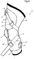
- a knee brace for the treatment of osteoarthritis is shown, globally indicated with reference number 10, comprising an upper half-shell 12, adapted to be constrained laterally to the thigh, and a lower half-shell 13, adapted to be constrained laterally to the calf, joined by an articulated rod 14, adapted to be placed laterally on the affected side of the knee that must be lightened by the load.
- the upper 12 and lower 13 half-shells comprise a structural core of plastic material and an outer coating of fabric.
- the half-shells 12 and 13 each have a constraining element, not shown, for opposite ends of the articulated rod, preferably adapted to make a removable constraint with the articulated rod 14.
- the upper 12 and lower 13 half-shells are further provided with fastening pins 15 for constraining the straps in an articulated manner, for example consisting of pins inserted in the structural core, to which constraining elements 16 for the straps, such as articulated slots 16' and 116', articulated loops or buckles 16" or articulated end plates 16''' are connected in an articulated manner, i.e. allowing a rotation about the axis defined by the pin.
- fastening pins 15 for constraining the straps in an articulated manner, for example consisting of pins inserted in the structural core, to which constraining elements 16 for the straps, such as articulated slots 16' and 116', articulated loops or buckles 16" or articulated end plates 16''' are connected in an articulated manner, i.e. allowing a rotation about the axis defined by the pin.
- the straps may be connected to the half-shells 12 and 13 through the articulated rod 14, being all or in part directly constrained, always in an articulated manner, directly on the ends of the articulated rod 14.
- the knee brace 10 further comprises a pressure plate 17 for the lateral support against the knee on the opposite side with respect to the articulated rod 14, which distributes the load on a surface having a plane extension and possibly a surface convexity modifiable as desired according to the patient's needs and anatomy.
- the pressure plate 17 comprises a structural portion, for example a structural core of plastic material, possibly provided with an outer fabric coating. On the side facing the knee, the pressure plate is further provided with a padded cushion 18 for improving comfort.
- the pressure plate 17 is provided with three fastening pins 15 for constraining the straps in an articulated manner, preferably arranged at the vertices of a triangle for a better distribution of the loads.
- the fastening pins 15 are connected in an articulated manner to three slots 16' or 116' for the straps, to which a rotation about the axis defined by the pin is allowed for the adaptation of the arrangement of the straps.
- the knee brace 10 comprises a strap system mainly consisting of an upper transverse front adjustment strap 19 adjustable in length, connected at opposite ends to the upper half-shell 12 and to the pressure plate 17, respectively, and a lower transverse front adjustment strap 20 adjustable in length, connected at opposite ends to the lower half-shell 13 and to the pressure plate 17, respectively.
- Each of the transverse front adjustment straps 19 and 20 comprises a first end fixed to an articulated end plate, not shown, and an opposite end returned in an articulated slot 16' so as to be folded on itself by means of a Velcro element for adjusting the desired length.
- the transverse front adjustment straps 19 and 20 are constrained via an articulated end plate to the half-shells 12 and 13 and have the end adjustable in length returned into the articulated slot 16' irremovably connected to the pressure plate 17.
- the knee brace 10 further comprises a single rear tightening strap 21, arranged on the rear side of the knee brace 10 according to two diagonals that, starting from the upper 12 and lower 13 half-shells, respectively, converge into the articulated slot 116', removably connectable to the pressure plate 17, for example through a quick release system 22.
- the articulated slot 116' provided with a quick release system 22 for the rear tightening strap 21 is positioned centrally with respect to the articulated slots 16' for the transverse front adjustment straps 19 and 20, irremovably connected to the pressure plate 17.
- a first end of the rear tightening strap 21 is connected to the upper half-shell 12 by means of a pulley tensioning device 23 for tensioning the knee brace 10 capable of demultiplying the forces that must be applied by the user, the tensioning to be achieved being equal.
- the pulley tensioning device 23 comprises a free slot 24, i.e. not directly constrained to the half-shells 12 and 13 or to the articulated rod 14, to which the end of the rear tightening strap 21 is fixed and in which a tensioning strap 25 is returned.
- the tensioning strap 25 is provided with an end constrained through an articulated end plate 16''' to the upper half-shell 12 and an opposite end provided with a gripping means 26, such as a ring, for exerting the traction.
- the tensioning strap 25 is foldable on itself by means of Velcro for a continuous adjustment of the length of the pulley tensioning device 23 and thus of the traction.
- An opposite end of the rear tightening strap 21 is instead connected to the lower half-shell 13 through an articulated loop or buckle 16" provided with anti-slip means 27 for the stable adjustment of the length of the rear tightening strap 21.
- the anti-slip means 27 may consist for example of portions of the loop coated with Velcro or anyway provided with a high friction surface and/or having a particular angle.
- the rear tightening strap 21 describes an upper diagonal between the fastening pin 15 on the upper half-shell 12 in the proximity of the articulated rod 14 and the return slot 116' of the pressure plate 17 and a lower diagonal between the return slot 116' of the pressure plate 17 and the fastening pin 15 on the lower half-shell 13 in the proximity of the articulated rod 14.
- the position of the pressure plate 17 on the patient's knee which is a freely floating element joined to the knee brace 10 only via straps 19, 20 and 21, is only determined by the adjustment of the length of the straps related thereto, and therefore is freely adjustable upon fitting the knee brace according to the specific medical needs and to the anatomy of the patient.
- the adjustment of the position of the pressure plate can take place both in height and moving forward or backward with respect to the joint.
- the adjustment of the position of the pressure plate 17 is carried out so as to place the single thrust point at the pressure plate 17 about symmetrically in "vertical" with respect to the two opposite thrust points at the ends of the articulated rod 14, as shown with arrows F in the figures.
- the adjustment along the circumference of the knee that allows adapting the knee brace as if it were a custom-made brace.
- the lateral support on the condyle-tibia must be calibrated for example according to the patient's anatomy, to the diffusion of osteoarthritis, etc., so as to obtain the best possible "opening" of the affected side and to find, also in the test phase upon the first application, the most comfortable configuration for the patient and that better soothes the pain.
- the knee brace 10 also includes a fabric sleeve 28, placed on the side of the knee brace facing the patient's leg, which protects the leg from the friction with the parts of the knee brace 10, in particular during the tightening operation.
- the fabric sleeve 28, preferably elastic, can be made as a closed tubular sock or possibly also open longitudinally.
- the fabric sleeve can be provided or not with a patellar hole.
- the knee brace comprises a lower strap 29, adjustable in length, connected in an articulated manner through slots 16' between two opposite points of the lower shell 12 for the circumferential clamping of the calf.
- the knee brace according to the invention may not have such a lower strap or it may also comprise an upper strap, adjustable in length, connected between two opposite points of the upper shell for the circumferential clamping of the thigh, not shown.
- the knee brace 10 upon the first application on a patient, provides for the adjustment of the upper 19 and lower 20 transverse front adjustment straps, as well as of the maximum length of the rear tightening strap 21 for defining the desired position of the pressure plate 17.
- the knee brace 10 is tensioned by means of the pulley tensioning device 23 of the rear tightening strap 21. This operation must be carried out with the knee flexed, when the rear portion of the knee brace is at the minimum length. In this way, the knee brace 10 exerts an even greater force when extending the knee, since the rear portion of the knee brace tends to "stretch". In fact, it is important that the knee brace exerts more strength with the knee extended and thus when standing, because the pain given by gonarthrosis occurs when standing and the articular surfaces are under the body weight's pressure. Instead, when sitting, the knee is relieved and therefore less force is required because it is not necessary to "distance" the joint surfaces.
- the force is exerted by the pressure plate 17, that is opposite the articulated rod 14, and by the two points at the ends of the articulated rod 14, so as to decrease the contact force between the femoral condyle and the lateral-presser portion of tibia, that is to say, to try to laterally "open” the knee joint as indicated by arrows F.
- the quick release system 22 of the articulated slot 116' removably connected to the pressure plate 17, in which the rear tightening strap 21 is returned, allows opening and wearing the knee brace without changing the adjustments of the lengths of the straps.
- the pressure plate 17 is only constrained to the three fastening pins 15 and, for a proper application of the corrective forces on the knee, through the correct adjustment of the transverse front adjustment straps 19 and 20 and of the rear tightening strap 21, it is positioned on the patient so as to laterally act on the knee at each application of the knee brace 10.
- the pressure plate 17 can be stably constrained to the fabric sleeve 28 in a lateral position, so as to be in the correct positioning when the knee brace is worn, and guide the adjustment of the straps 19, 20, 21.
- this constraint can be made through a sewing 18' between the sleeve 28 and for example the padded cushion 18, in turn integrally joined to the pressure plate 17.
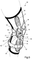
- the constraint between the pressure plate 17 and the sleeve 28 is obtained by making the pressure plate 17 integral to a second articulated rod 30, arranged on the opposite side of the knee brace 10 with respect to articulated rod 14.
- the pressure plate 17 is made integral to the second articulated rod 30, for instance by making the pressure plate 17 coincide with the articulation portion of the second articulated rod 30, to which the fastening pins 15 are for example directly connected, as shown in figure 9 .
- the second articulated rod 30 is in turn stably constrained to the sleeve 28, for example through the provision of pockets 31 sewed on the sleeve 28 itself for the insertion of the opposite ends of the second articulated rod 30.
- the padded cushion 18 can be directly applied to the sleeve 28 through a sewing 18' and can be itself constrained to the second articulated rod 30, for instance through the provision of constraining means such as Velcro®, not shown, in order to contribute to the positioning of the second articulated rod 30 with respect to the sleeve 28.
- the knee brace for the treatment of osteoarthritis subject-matter of the present invention has the advantage of allowing the positioning of the pressure plate in height and along the circumference of the knee to adjust the pressure point as desired.
- the knee brace of the invention advantageously provides for carrying out the adjustments of the lengths of the straps just during the first application. Moreover, it advantageously comprises a quick release system of the pressure plate to open the knee brace in order to easily wear it.
- the knee brace of the invention is advantageously tightened by means of a pulley device that demultiplies the force that must be applied, the tensioning of the knee brace being the same.
- a further advantage consists in that the tightening operation can be carried out with the knee flexed when the rear portion of the knee brace is at the minimum length and in that upon the knee extension, the knee brace will exert an even greater force.
Landscapes
- Health & Medical Sciences (AREA)
- Animal Behavior & Ethology (AREA)
- Life Sciences & Earth Sciences (AREA)
- Engineering & Computer Science (AREA)
- Biomedical Technology (AREA)
- General Health & Medical Sciences (AREA)
- Vascular Medicine (AREA)
- Orthopedic Medicine & Surgery (AREA)
- Nursing (AREA)
- Heart & Thoracic Surgery (AREA)
- Public Health (AREA)
- Veterinary Medicine (AREA)
- Orthopedics, Nursing, And Contraception (AREA)
- Steroid Compounds (AREA)
- Eye Examination Apparatus (AREA)
- Housing For Livestock And Birds (AREA)
- Pharmaceuticals Containing Other Organic And Inorganic Compounds (AREA)
Claims (13)
- Orthèse de genou pour le traitement de l'arthrose comprenant une demi-coque supérieure (12) et une demi-coque inférieure (13), réunies par une tige articulée (14), ainsi qu'une plaque de pression (17) pour le support latéral contre le genou du côté opposé par rapport à ladite tige articulée (14), ladite orthèse de genou comprend un système de sangle comprenant une sangle de réglage avant transversale supérieure (19), réglable en longueur, reliée aux extrémités opposées à ladite demi-coque supérieure (12) et à ladite plaque de pression (17), respectivement, et une sangle de réglage avant transversale inférieure (20), réglable en longueur, reliée aux extrémités opposées à ladite demi-coque inférieure (13) et à ladite plaque de pression (17), respectivement, ainsi qu'une seule sangle de serrage arrière (21), réglable en longueur et pourvue d'un dispositif de tension à poulie (23), agencée sur le côté arrière de l'orthèse de genou (10) le long de deux diagonales qui partant de ladite demi-coque supérieure (12) et de ladite demi-coque inférieure (13), respectivement, convergent vers une fente articulée (116') de ladite plaque de pression (17), dans laquelle lesdites sangles sont reliées de manière mobile ou non auxdites demi-coques (12, 13) et à ladite plaque de pression (17) exclusivement de manière articulée à travers des éléments de contrainte (16), tels que des fentes articulées (16', 116') et/ou des boucles articulées (16") et/ou des plaques d'extrémité articulées (16'''), adaptées pour permettre la rotation des sangles.
- Orthèse de genou selon la revendication 1, caractérisée en ce que lesdites demi-coques supérieure (12) et inférieure (13) et ladite plaque de pression (17) sont munies de goupilles de fixation (15) pour contraindre de manière articulée, mobile ou non, les moyens d'accrochage (16) des dites sangles, lesdites goupilles de fixation (15) étant de préférence insérées dans un noyau structurel.
- Orthèse de genou selon la revendication 2, caractérisée en ce que ladite plaque de pression (17) est pourvue de trois goupilles de fixation (15) disposées aux sommets d'un triangle pour une meilleure répartition des charges.
- Orthèse de genou selon la revendication 1 ou 2, caractérisée en ce que lesdites sangles de réglage avant transversales (19 et 20) sont contraintes à une extrémité auxdites demi-coques (12 et 13) au moyen de ladite plaque d'extrémité articulée (16''') et dont l'extrémité opposée réglable en longueur est retournée dans ladite fente articulée (16') reliée de façon non-mobile à ladite plaque de pression (17).
- Orthèse de genou selon l'une quelconque des revendications précédentes, caractérisée en ce que ledit dispositif de tension à poulie (23) comprend une sangle de tension (25) munie d'une extrémité contrainte au moyen d'une plaque d'extrémité articulée (16''') à ladite demi-coque supérieure (12) et avec une extrémité opposée pourvue d'un moyen de préhension (26), ladite sangle de tension (25) étant retournée dans une fente libre (24) à laquelle une extrémité de la sangle de serrage arrière (21) est fixée, ladite sangle de tension (25) étant repliable sur elle-même au moyen de velcro pour un réglage continu de la traction.
- Orthèse de genou selon l'une quelconque des revendications précédentes, caractérisée en ce qu'une extrémité réglable en longueur de ladite sangle de serrage arrière (21) est reliée à ladite demi-coque inférieure (13) par une boucle articulée (16"), de préférence munie de moyens antidérapants (27) pour la stabilisation du réglage en longueur de ladite sangle de serrage arrière (21).
- Orthèse de genou selon l'une quelconque des revendications précédentes, caractérisée en ce que ladite fente articulée (116') pour la connexion mobile de ladite sangle de serrage arrière (21) à ladite plaque de pression (17) est munie d'un système à largage rapide (22).
- Orthèse de genou selon l'une quelconque des revendications précédentes, caractérisée en ce que ladite fente articulée (116') de connexion mobile de ladite sangle de serrage arrière (21) à ladite plaque de pression (17) est positionnée centralement par rapport auxdites fentes articulées non mobiles (16') pour lesdites sangles de réglage avant transversales (19 et 20).
- Orthèse de genou selon l'une quelconque des revendications précédentes, caractérisée en ce que ledit système de sangle comprend en outre au moins une sangle inférieure (29), réglable en longueur, reliée de manière articulée entre deux points opposés de ladite coque inférieure (12) pour le serrage circonférentiel du mollet.
- Orthèse de genou selon l'une quelconque des revendications précédentes, caractérisée en ce qu'elle comprend un manchon en tissu (28), disposé du côté de l'orthèse de genou (10) en regard de la jambe du patient.
- Orthèse de genou selon la revendication 10, caractérisée en ce que ladite plaque de pression (17) est contrainte de manière stable audit manchon en tissu (28).
- Orthèse de genou selon la revendication 11, caractérisée en ce que ladite plaque de pression (17) est contrainte de manière stable audit manchon en tissu (28) au moyen d'une couture (18').
- Orthèse de genou selon la revendication 11, caractérisée en ce que ladite plaque de pression (17) est solidaire d'une deuxième tige articulée (30), les extrémités opposées de ladite deuxième tige articulée (30) étant contraintes de manière stable audit manchon (28).
Priority Applications (2)
| Application Number | Priority Date | Filing Date | Title |
|---|---|---|---|
| PL16181861T PL3123986T3 (pl) | 2015-07-31 | 2016-07-29 | Orteza stawu kolanowego do leczenia zapalenia kości i stawów |
| HRP20180852TT HRP20180852T1 (hr) | 2015-07-31 | 2018-05-29 | Proteza za koljeno za liječenje osteoartritisa |
Applications Claiming Priority (1)
| Application Number | Priority Date | Filing Date | Title |
|---|---|---|---|
| ITUB2015A002714A ITUB20152714A1 (it) | 2015-07-31 | 2015-07-31 | Ginocchiera per il trattamento dell?osteoartrite. |
Publications (2)
| Publication Number | Publication Date |
|---|---|
| EP3123986A1 EP3123986A1 (fr) | 2017-02-01 |
| EP3123986B1 true EP3123986B1 (fr) | 2018-03-14 |
Family
ID=54364569
Family Applications (1)
| Application Number | Title | Priority Date | Filing Date |
|---|---|---|---|
| EP16181861.2A Active EP3123986B1 (fr) | 2015-07-31 | 2016-07-29 | Orthèse de genou pour le traitement de l'arthrose |
Country Status (4)
| Country | Link |
|---|---|
| EP (1) | EP3123986B1 (fr) |
| HR (1) | HRP20180852T1 (fr) |
| IT (1) | ITUB20152714A1 (fr) |
| PL (1) | PL3123986T3 (fr) |
Cited By (1)
| Publication number | Priority date | Publication date | Assignee | Title |
|---|---|---|---|---|
| DE102021002999A1 (de) | 2021-06-14 | 2022-12-15 | Felix Carstens | Orthopädische Einrichtung zur Erzeugung von bewegungswinkelabhängigen Kräften |
Families Citing this family (3)
| Publication number | Priority date | Publication date | Assignee | Title |
|---|---|---|---|---|
| US11484425B2 (en) * | 2017-12-15 | 2022-11-01 | Stoko Design Inc. | Apparatus and method for stabilizing a human anatomical joint |
| US11857448B2 (en) * | 2018-02-02 | 2024-01-02 | Otto Bock Healthcare Lp | Methods and apparatus for treating osteoarthritis of the knee |
| DE102018132957B4 (de) * | 2018-12-19 | 2024-09-05 | Ottobock Se & Co. Kgaa | Knieorthese |
Family Cites Families (6)
| Publication number | Priority date | Publication date | Assignee | Title |
|---|---|---|---|---|
| DE846895C (de) * | 1950-11-16 | 1952-08-18 | Karl Roemer | Kniekappe zur Stuetzung von erkrankten Kniegelenken |
| DE8517061U1 (de) * | 1985-06-12 | 1985-09-05 | Sanitätshaus Heinz Pfau GmbH & Co KG, 1000 Berlin | Knieführungsanordnung zur Korrektur einer Fehlstellung des Kniegelenks |
| US5277698A (en) * | 1991-05-08 | 1994-01-11 | Generation Ii Orthotics, Inc. | Knee bracing method |
| US6110138A (en) * | 1999-02-01 | 2000-08-29 | Tagg Industries, L.L.C. | Stance-correcting knee brace |
| US7198610B2 (en) | 2004-12-22 | 2007-04-03 | Ossur Hf | Knee brace and method for securing the same |
| US7867183B2 (en) * | 2005-09-30 | 2011-01-11 | Dj Orthopedics, Llc | Knee brace having a rigid frame and patellofemoral support |
-
2015
- 2015-07-31 IT ITUB2015A002714A patent/ITUB20152714A1/it unknown
-
2016
- 2016-07-29 EP EP16181861.2A patent/EP3123986B1/fr active Active
- 2016-07-29 PL PL16181861T patent/PL3123986T3/pl unknown
-
2018
- 2018-05-29 HR HRP20180852TT patent/HRP20180852T1/hr unknown
Non-Patent Citations (1)
| Title |
|---|
| None * |
Cited By (1)
| Publication number | Priority date | Publication date | Assignee | Title |
|---|---|---|---|---|
| DE102021002999A1 (de) | 2021-06-14 | 2022-12-15 | Felix Carstens | Orthopädische Einrichtung zur Erzeugung von bewegungswinkelabhängigen Kräften |
Also Published As
| Publication number | Publication date |
|---|---|
| ITUB20152714A1 (it) | 2017-01-31 |
| PL3123986T3 (pl) | 2018-09-28 |
| HRP20180852T1 (hr) | 2018-08-24 |
| EP3123986A1 (fr) | 2017-02-01 |
Similar Documents
| Publication | Publication Date | Title |
|---|---|---|
| US11304838B2 (en) | Support for articles and methods for using the same | |
| US9532895B2 (en) | Patellofemoral device and method for using the same | |
| CA2852695C (fr) | Dispositif orthopedique pour le traitement dynamique du genou | |
| US9271860B2 (en) | Orthopedic device | |
| EP3123986B1 (fr) | Orthèse de genou pour le traitement de l'arthrose | |
| US8672865B2 (en) | Weight-bearing lower extremity brace | |
| US8403872B2 (en) | Weight-bearing lower extremity brace | |
| US20120220910A1 (en) | Knee support device having adjustable openings at opposing ends | |
| AU2016338678B2 (en) | Customizable knee brace intended for patients with osteoarthritis | |
| DK2571462T3 (en) | Hip support device | |
| JP7386316B2 (ja) | 曲がった脚変形に対する下部体形及び歩行矯正用圧迫衣類 | |
| US20230201018A1 (en) | Orthopedic bracing system and method of use | |
| US8956316B2 (en) | Knee orthosis for torn anterior cruciate ligament | |
| US8894595B2 (en) | Traction hip brace | |
| US20160250058A1 (en) | Orthopedic kneepad | |
| CN218870611U (zh) | 一种下肢矫正装具 | |
| JP2022506257A (ja) | 人体関節安定化ガーメント | |
| CN113101027B (zh) | 一种柔性膝关节矫形医疗辅助器械 | |
| US20230240874A1 (en) | Single-upright osteoarthritis braces and related methods | |
| WO2017072478A1 (fr) | Orthèse de genou | |
| JP2022113414A (ja) | 膝装具 |
Legal Events
| Date | Code | Title | Description |
|---|---|---|---|
| PUAI | Public reference made under article 153(3) epc to a published international application that has entered the european phase |
Free format text: ORIGINAL CODE: 0009012 |
|
| AK | Designated contracting states |
Kind code of ref document: A1 Designated state(s): AL AT BE BG CH CY CZ DE DK EE ES FI FR GB GR HR HU IE IS IT LI LT LU LV MC MK MT NL NO PL PT RO RS SE SI SK SM TR |
|
| AX | Request for extension of the european patent |
Extension state: BA ME |
|
| 17P | Request for examination filed |
Effective date: 20170616 |
|
| RBV | Designated contracting states (corrected) |
Designated state(s): AL AT BE BG CH CY CZ DE DK EE ES FI FR GB GR HR HU IE IS IT LI LT LU LV MC MK MT NL NO PL PT RO RS SE SI SK SM TR |
|
| RIC1 | Information provided on ipc code assigned before grant |
Ipc: A61F 5/01 20060101AFI20170821BHEP |
|
| GRAP | Despatch of communication of intention to grant a patent |
Free format text: ORIGINAL CODE: EPIDOSNIGR1 |
|
| INTG | Intention to grant announced |
Effective date: 20171006 |
|
| GRAS | Grant fee paid |
Free format text: ORIGINAL CODE: EPIDOSNIGR3 |
|
| GRAA | (expected) grant |
Free format text: ORIGINAL CODE: 0009210 |
|
| AK | Designated contracting states |
Kind code of ref document: B1 Designated state(s): AL AT BE BG CH CY CZ DE DK EE ES FI FR GB GR HR HU IE IS IT LI LT LU LV MC MK MT NL NO PL PT RO RS SE SI SK SM TR |
|
| REG | Reference to a national code |
Ref country code: GB Ref legal event code: FG4D |
|
| REG | Reference to a national code |
Ref country code: AT Ref legal event code: REF Ref document number: 978123 Country of ref document: AT Kind code of ref document: T Effective date: 20180315 Ref country code: CH Ref legal event code: EP |
|
| REG | Reference to a national code |
Ref country code: IE Ref legal event code: FG4D |
|
| REG | Reference to a national code |
Ref country code: DE Ref legal event code: R096 Ref document number: 602016001992 Country of ref document: DE |
|
| REG | Reference to a national code |
Ref country code: HR Ref legal event code: TUEP Ref document number: P20180852 Country of ref document: HR |
|
| REG | Reference to a national code |
Ref country code: SE Ref legal event code: TRGR |
|
| REG | Reference to a national code |
Ref country code: NL Ref legal event code: FP |
|
| REG | Reference to a national code |
Ref country code: FR Ref legal event code: PLFP Year of fee payment: 3 |
|
| REG | Reference to a national code |
Ref country code: LT Ref legal event code: MG4D |
|
| PG25 | Lapsed in a contracting state [announced via postgrant information from national office to epo] |
Ref country code: CY Free format text: LAPSE BECAUSE OF FAILURE TO SUBMIT A TRANSLATION OF THE DESCRIPTION OR TO PAY THE FEE WITHIN THE PRESCRIBED TIME-LIMIT Effective date: 20180314 Ref country code: LT Free format text: LAPSE BECAUSE OF FAILURE TO SUBMIT A TRANSLATION OF THE DESCRIPTION OR TO PAY THE FEE WITHIN THE PRESCRIBED TIME-LIMIT Effective date: 20180314 Ref country code: NO Free format text: LAPSE BECAUSE OF FAILURE TO SUBMIT A TRANSLATION OF THE DESCRIPTION OR TO PAY THE FEE WITHIN THE PRESCRIBED TIME-LIMIT Effective date: 20180614 |
|
| REG | Reference to a national code |
Ref country code: AT Ref legal event code: MK05 Ref document number: 978123 Country of ref document: AT Kind code of ref document: T Effective date: 20180314 |
|
| REG | Reference to a national code |
Ref country code: HR Ref legal event code: T1PR Ref document number: P20180852 Country of ref document: HR |
|
| PG25 | Lapsed in a contracting state [announced via postgrant information from national office to epo] |
Ref country code: RS Free format text: LAPSE BECAUSE OF FAILURE TO SUBMIT A TRANSLATION OF THE DESCRIPTION OR TO PAY THE FEE WITHIN THE PRESCRIBED TIME-LIMIT Effective date: 20180314 Ref country code: LV Free format text: LAPSE BECAUSE OF FAILURE TO SUBMIT A TRANSLATION OF THE DESCRIPTION OR TO PAY THE FEE WITHIN THE PRESCRIBED TIME-LIMIT Effective date: 20180314 Ref country code: GR Free format text: LAPSE BECAUSE OF FAILURE TO SUBMIT A TRANSLATION OF THE DESCRIPTION OR TO PAY THE FEE WITHIN THE PRESCRIBED TIME-LIMIT Effective date: 20180615 Ref country code: BG Free format text: LAPSE BECAUSE OF FAILURE TO SUBMIT A TRANSLATION OF THE DESCRIPTION OR TO PAY THE FEE WITHIN THE PRESCRIBED TIME-LIMIT Effective date: 20180614 |
|
| PG25 | Lapsed in a contracting state [announced via postgrant information from national office to epo] |
Ref country code: RO Free format text: LAPSE BECAUSE OF FAILURE TO SUBMIT A TRANSLATION OF THE DESCRIPTION OR TO PAY THE FEE WITHIN THE PRESCRIBED TIME-LIMIT Effective date: 20180314 Ref country code: ES Free format text: LAPSE BECAUSE OF FAILURE TO SUBMIT A TRANSLATION OF THE DESCRIPTION OR TO PAY THE FEE WITHIN THE PRESCRIBED TIME-LIMIT Effective date: 20180314 Ref country code: AL Free format text: LAPSE BECAUSE OF FAILURE TO SUBMIT A TRANSLATION OF THE DESCRIPTION OR TO PAY THE FEE WITHIN THE PRESCRIBED TIME-LIMIT Effective date: 20180314 Ref country code: EE Free format text: LAPSE BECAUSE OF FAILURE TO SUBMIT A TRANSLATION OF THE DESCRIPTION OR TO PAY THE FEE WITHIN THE PRESCRIBED TIME-LIMIT Effective date: 20180314 |
|
| PG25 | Lapsed in a contracting state [announced via postgrant information from national office to epo] |
Ref country code: SK Free format text: LAPSE BECAUSE OF FAILURE TO SUBMIT A TRANSLATION OF THE DESCRIPTION OR TO PAY THE FEE WITHIN THE PRESCRIBED TIME-LIMIT Effective date: 20180314 Ref country code: SM Free format text: LAPSE BECAUSE OF FAILURE TO SUBMIT A TRANSLATION OF THE DESCRIPTION OR TO PAY THE FEE WITHIN THE PRESCRIBED TIME-LIMIT Effective date: 20180314 Ref country code: CZ Free format text: LAPSE BECAUSE OF FAILURE TO SUBMIT A TRANSLATION OF THE DESCRIPTION OR TO PAY THE FEE WITHIN THE PRESCRIBED TIME-LIMIT Effective date: 20180314 Ref country code: AT Free format text: LAPSE BECAUSE OF FAILURE TO SUBMIT A TRANSLATION OF THE DESCRIPTION OR TO PAY THE FEE WITHIN THE PRESCRIBED TIME-LIMIT Effective date: 20180314 |
|
| REG | Reference to a national code |
Ref country code: DE Ref legal event code: R097 Ref document number: 602016001992 Country of ref document: DE |
|
| PG25 | Lapsed in a contracting state [announced via postgrant information from national office to epo] |
Ref country code: PT Free format text: LAPSE BECAUSE OF FAILURE TO SUBMIT A TRANSLATION OF THE DESCRIPTION OR TO PAY THE FEE WITHIN THE PRESCRIBED TIME-LIMIT Effective date: 20180716 |
|
| PLBE | No opposition filed within time limit |
Free format text: ORIGINAL CODE: 0009261 |
|
| STAA | Information on the status of an ep patent application or granted ep patent |
Free format text: STATUS: NO OPPOSITION FILED WITHIN TIME LIMIT |
|
| PG25 | Lapsed in a contracting state [announced via postgrant information from national office to epo] |
Ref country code: DK Free format text: LAPSE BECAUSE OF FAILURE TO SUBMIT A TRANSLATION OF THE DESCRIPTION OR TO PAY THE FEE WITHIN THE PRESCRIBED TIME-LIMIT Effective date: 20180314 |
|
| 26N | No opposition filed |
Effective date: 20181217 |
|
| PG25 | Lapsed in a contracting state [announced via postgrant information from national office to epo] |
Ref country code: SI Free format text: LAPSE BECAUSE OF FAILURE TO SUBMIT A TRANSLATION OF THE DESCRIPTION OR TO PAY THE FEE WITHIN THE PRESCRIBED TIME-LIMIT Effective date: 20180314 |
|
| PG25 | Lapsed in a contracting state [announced via postgrant information from national office to epo] |
Ref country code: MC Free format text: LAPSE BECAUSE OF FAILURE TO SUBMIT A TRANSLATION OF THE DESCRIPTION OR TO PAY THE FEE WITHIN THE PRESCRIBED TIME-LIMIT Effective date: 20180314 Ref country code: LU Free format text: LAPSE BECAUSE OF NON-PAYMENT OF DUE FEES Effective date: 20180729 |
|
| REG | Reference to a national code |
Ref country code: IE Ref legal event code: MM4A |
|
| PG25 | Lapsed in a contracting state [announced via postgrant information from national office to epo] |
Ref country code: IE Free format text: LAPSE BECAUSE OF NON-PAYMENT OF DUE FEES Effective date: 20180729 |
|
| REG | Reference to a national code |
Ref country code: HR Ref legal event code: ODRP Ref document number: P20180852 Country of ref document: HR Payment date: 20190724 Year of fee payment: 4 |
|
| PG25 | Lapsed in a contracting state [announced via postgrant information from national office to epo] |
Ref country code: MT Free format text: LAPSE BECAUSE OF NON-PAYMENT OF DUE FEES Effective date: 20180729 |
|
| PG25 | Lapsed in a contracting state [announced via postgrant information from national office to epo] |
Ref country code: TR Free format text: LAPSE BECAUSE OF FAILURE TO SUBMIT A TRANSLATION OF THE DESCRIPTION OR TO PAY THE FEE WITHIN THE PRESCRIBED TIME-LIMIT Effective date: 20180314 |
|
| PG25 | Lapsed in a contracting state [announced via postgrant information from national office to epo] |
Ref country code: HU Free format text: LAPSE BECAUSE OF FAILURE TO SUBMIT A TRANSLATION OF THE DESCRIPTION OR TO PAY THE FEE WITHIN THE PRESCRIBED TIME-LIMIT; INVALID AB INITIO Effective date: 20160729 Ref country code: MK Free format text: LAPSE BECAUSE OF NON-PAYMENT OF DUE FEES Effective date: 20180314 |
|
| PG25 | Lapsed in a contracting state [announced via postgrant information from national office to epo] |
Ref country code: IS Free format text: LAPSE BECAUSE OF FAILURE TO SUBMIT A TRANSLATION OF THE DESCRIPTION OR TO PAY THE FEE WITHIN THE PRESCRIBED TIME-LIMIT Effective date: 20180714 |
|
| REG | Reference to a national code |
Ref country code: HR Ref legal event code: ODRP Ref document number: P20180852 Country of ref document: HR Payment date: 20200721 Year of fee payment: 5 |
|
| REG | Reference to a national code |
Ref country code: HR Ref legal event code: ODRP Ref document number: P20180852 Country of ref document: HR Payment date: 20210727 Year of fee payment: 6 |
|
| PGFP | Annual fee paid to national office [announced via postgrant information from national office to epo] |
Ref country code: SE Payment date: 20220615 Year of fee payment: 7 Ref country code: NL Payment date: 20220615 Year of fee payment: 7 Ref country code: GB Payment date: 20220609 Year of fee payment: 7 |
|
| PGFP | Annual fee paid to national office [announced via postgrant information from national office to epo] |
Ref country code: PL Payment date: 20220621 Year of fee payment: 7 Ref country code: BE Payment date: 20220615 Year of fee payment: 7 |
|
| REG | Reference to a national code |
Ref country code: HR Ref legal event code: ODRP Ref document number: P20180852 Country of ref document: HR Payment date: 20220727 Year of fee payment: 7 |
|
| PGFP | Annual fee paid to national office [announced via postgrant information from national office to epo] |
Ref country code: FR Payment date: 20220609 Year of fee payment: 7 |
|
| PGFP | Annual fee paid to national office [announced via postgrant information from national office to epo] |
Ref country code: IT Payment date: 20220706 Year of fee payment: 7 Ref country code: HR Payment date: 20220727 Year of fee payment: 7 Ref country code: FI Payment date: 20220712 Year of fee payment: 7 Ref country code: DE Payment date: 20220608 Year of fee payment: 7 |
|
| PGFP | Annual fee paid to national office [announced via postgrant information from national office to epo] |
Ref country code: CH Payment date: 20220801 Year of fee payment: 7 |
|
| P01 | Opt-out of the competence of the unified patent court (upc) registered |
Effective date: 20230504 |
|
| REG | Reference to a national code |
Ref country code: DE Ref legal event code: R119 Ref document number: 602016001992 Country of ref document: DE |
|
| REG | Reference to a national code |
Ref country code: HR Ref legal event code: PBON Ref document number: P20180852 Country of ref document: HR Effective date: 20230729 |
|
| REG | Reference to a national code |
Ref country code: CH Ref legal event code: PL |
|
| REG | Reference to a national code |
Ref country code: SE Ref legal event code: EUG |
|
| REG | Reference to a national code |
Ref country code: NL Ref legal event code: MM Effective date: 20230801 |
|
| REG | Reference to a national code |
Ref country code: BE Ref legal event code: MM Effective date: 20230731 |
|
| GBPC | Gb: european patent ceased through non-payment of renewal fee |
Effective date: 20230729 |
|
| PG25 | Lapsed in a contracting state [announced via postgrant information from national office to epo] |
Ref country code: NL Free format text: LAPSE BECAUSE OF NON-PAYMENT OF DUE FEES Effective date: 20230801 |
|
| PG25 | Lapsed in a contracting state [announced via postgrant information from national office to epo] |
Ref country code: NL Free format text: LAPSE BECAUSE OF NON-PAYMENT OF DUE FEES Effective date: 20230801 Ref country code: FI Free format text: LAPSE BECAUSE OF NON-PAYMENT OF DUE FEES Effective date: 20230729 Ref country code: DE Free format text: LAPSE BECAUSE OF NON-PAYMENT OF DUE FEES Effective date: 20240201 Ref country code: CH Free format text: LAPSE BECAUSE OF NON-PAYMENT OF DUE FEES Effective date: 20230731 Ref country code: GB Free format text: LAPSE BECAUSE OF NON-PAYMENT OF DUE FEES Effective date: 20230729 |
|
| PG25 | Lapsed in a contracting state [announced via postgrant information from national office to epo] |
Ref country code: SE Free format text: LAPSE BECAUSE OF NON-PAYMENT OF DUE FEES Effective date: 20230730 Ref country code: HR Free format text: LAPSE BECAUSE OF NON-PAYMENT OF DUE FEES Effective date: 20230729 Ref country code: FR Free format text: LAPSE BECAUSE OF NON-PAYMENT OF DUE FEES Effective date: 20230731 Ref country code: BE Free format text: LAPSE BECAUSE OF NON-PAYMENT OF DUE FEES Effective date: 20230731 |
|
| PG25 | Lapsed in a contracting state [announced via postgrant information from national office to epo] |
Ref country code: IT Free format text: LAPSE BECAUSE OF NON-PAYMENT OF DUE FEES Effective date: 20230729 |