EP3123544B1 - Reacteur implantable biocompatible - Google Patents
Reacteur implantable biocompatible Download PDFInfo
- Publication number
- EP3123544B1 EP3123544B1 EP15718517.4A EP15718517A EP3123544B1 EP 3123544 B1 EP3123544 B1 EP 3123544B1 EP 15718517 A EP15718517 A EP 15718517A EP 3123544 B1 EP3123544 B1 EP 3123544B1
- Authority
- EP
- European Patent Office
- Prior art keywords
- chitosan
- bioreactor
- pellet
- membrane
- compression
- Prior art date
- Legal status (The legal status is an assumption and is not a legal conclusion. Google has not performed a legal analysis and makes no representation as to the accuracy of the status listed.)
- Active
Links
Images

Classifications
-
- C—CHEMISTRY; METALLURGY
- C12—BIOCHEMISTRY; BEER; SPIRITS; WINE; VINEGAR; MICROBIOLOGY; ENZYMOLOGY; MUTATION OR GENETIC ENGINEERING
- C12M—APPARATUS FOR ENZYMOLOGY OR MICROBIOLOGY; APPARATUS FOR CULTURING MICROORGANISMS FOR PRODUCING BIOMASS, FOR GROWING CELLS OR FOR OBTAINING FERMENTATION OR METABOLIC PRODUCTS, i.e. BIOREACTORS OR FERMENTERS
- C12M29/00—Means for introduction, extraction or recirculation of materials, e.g. pumps
- C12M29/04—Filters; Permeable or porous membranes or plates, e.g. dialysis
-
- B—PERFORMING OPERATIONS; TRANSPORTING
- B29—WORKING OF PLASTICS; WORKING OF SUBSTANCES IN A PLASTIC STATE IN GENERAL
- B29C—SHAPING OR JOINING OF PLASTICS; SHAPING OF MATERIAL IN A PLASTIC STATE, NOT OTHERWISE PROVIDED FOR; AFTER-TREATMENT OF THE SHAPED PRODUCTS, e.g. REPAIRING
- B29C41/00—Shaping by coating a mould, core or other substrate, i.e. by depositing material and stripping-off the shaped article; Apparatus therefor
- B29C41/003—Shaping by coating a mould, core or other substrate, i.e. by depositing material and stripping-off the shaped article; Apparatus therefor characterised by the choice of material
-
- B—PERFORMING OPERATIONS; TRANSPORTING
- B29—WORKING OF PLASTICS; WORKING OF SUBSTANCES IN A PLASTIC STATE IN GENERAL
- B29C—SHAPING OR JOINING OF PLASTICS; SHAPING OF MATERIAL IN A PLASTIC STATE, NOT OTHERWISE PROVIDED FOR; AFTER-TREATMENT OF THE SHAPED PRODUCTS, e.g. REPAIRING
- B29C65/00—Joining or sealing of preformed parts, e.g. welding of plastics materials; Apparatus therefor
- B29C65/48—Joining or sealing of preformed parts, e.g. welding of plastics materials; Apparatus therefor using adhesives, i.e. using supplementary joining material; solvent bonding
- B29C65/4805—Joining or sealing of preformed parts, e.g. welding of plastics materials; Apparatus therefor using adhesives, i.e. using supplementary joining material; solvent bonding characterised by the type of adhesives
-
- G—PHYSICS
- G01—MEASURING; TESTING
- G01N—INVESTIGATING OR ANALYSING MATERIALS BY DETERMINING THEIR CHEMICAL OR PHYSICAL PROPERTIES
- G01N27/00—Investigating or analysing materials by the use of electric, electrochemical, or magnetic means
- G01N27/26—Investigating or analysing materials by the use of electric, electrochemical, or magnetic means by investigating electrochemical variables; by using electrolysis or electrophoresis
- G01N27/28—Electrolytic cell components
- G01N27/30—Electrodes, e.g. test electrodes; Half-cells
- G01N27/327—Biochemical electrodes, e.g. electrical or mechanical details for in vitro measurements
- G01N27/3271—Amperometric enzyme electrodes for analytes in body fluids, e.g. glucose in blood
-
- H—ELECTRICITY
- H01—ELECTRIC ELEMENTS
- H01M—PROCESSES OR MEANS, e.g. BATTERIES, FOR THE DIRECT CONVERSION OF CHEMICAL ENERGY INTO ELECTRICAL ENERGY
- H01M4/00—Electrodes
- H01M4/86—Inert electrodes with catalytic activity, e.g. for fuel cells
- H01M4/8605—Porous electrodes
-
- H—ELECTRICITY
- H01—ELECTRIC ELEMENTS
- H01M—PROCESSES OR MEANS, e.g. BATTERIES, FOR THE DIRECT CONVERSION OF CHEMICAL ENERGY INTO ELECTRICAL ENERGY
- H01M4/00—Electrodes
- H01M4/86—Inert electrodes with catalytic activity, e.g. for fuel cells
- H01M4/8663—Selection of inactive substances as ingredients for catalytic active masses, e.g. binders, fillers
-
- H—ELECTRICITY
- H01—ELECTRIC ELEMENTS
- H01M—PROCESSES OR MEANS, e.g. BATTERIES, FOR THE DIRECT CONVERSION OF CHEMICAL ENERGY INTO ELECTRICAL ENERGY
- H01M4/00—Electrodes
- H01M4/86—Inert electrodes with catalytic activity, e.g. for fuel cells
- H01M4/8663—Selection of inactive substances as ingredients for catalytic active masses, e.g. binders, fillers
- H01M4/8673—Electrically conductive fillers
-
- H—ELECTRICITY
- H01—ELECTRIC ELEMENTS
- H01M—PROCESSES OR MEANS, e.g. BATTERIES, FOR THE DIRECT CONVERSION OF CHEMICAL ENERGY INTO ELECTRICAL ENERGY
- H01M4/00—Electrodes
- H01M4/86—Inert electrodes with catalytic activity, e.g. for fuel cells
- H01M4/88—Processes of manufacture
- H01M4/8878—Treatment steps after deposition of the catalytic active composition or after shaping of the electrode being free-standing body
- H01M4/8896—Pressing, rolling, calendering
-
- H—ELECTRICITY
- H01—ELECTRIC ELEMENTS
- H01M—PROCESSES OR MEANS, e.g. BATTERIES, FOR THE DIRECT CONVERSION OF CHEMICAL ENERGY INTO ELECTRICAL ENERGY
- H01M4/00—Electrodes
- H01M4/86—Inert electrodes with catalytic activity, e.g. for fuel cells
- H01M4/90—Selection of catalytic material
- H01M4/9008—Organic or organo-metallic compounds
-
- H—ELECTRICITY
- H01—ELECTRIC ELEMENTS
- H01M—PROCESSES OR MEANS, e.g. BATTERIES, FOR THE DIRECT CONVERSION OF CHEMICAL ENERGY INTO ELECTRICAL ENERGY
- H01M4/00—Electrodes
- H01M4/86—Inert electrodes with catalytic activity, e.g. for fuel cells
- H01M4/90—Selection of catalytic material
- H01M4/9075—Catalytic material supported on carriers, e.g. powder carriers
- H01M4/9083—Catalytic material supported on carriers, e.g. powder carriers on carbon or graphite
-
- H—ELECTRICITY
- H01—ELECTRIC ELEMENTS
- H01M—PROCESSES OR MEANS, e.g. BATTERIES, FOR THE DIRECT CONVERSION OF CHEMICAL ENERGY INTO ELECTRICAL ENERGY
- H01M8/00—Fuel cells; Manufacture thereof
- H01M8/16—Biochemical fuel cells, i.e. cells in which microorganisms function as catalysts
-
- B—PERFORMING OPERATIONS; TRANSPORTING
- B29—WORKING OF PLASTICS; WORKING OF SUBSTANCES IN A PLASTIC STATE IN GENERAL
- B29K—INDEXING SCHEME ASSOCIATED WITH SUBCLASSES B29B, B29C OR B29D, RELATING TO MOULDING MATERIALS OR TO MATERIALS FOR MOULDS, REINFORCEMENTS, FILLERS OR PREFORMED PARTS, e.g. INSERTS
- B29K2005/00—Use of polysaccharides or derivatives as moulding material
-
- B—PERFORMING OPERATIONS; TRANSPORTING
- B29—WORKING OF PLASTICS; WORKING OF SUBSTANCES IN A PLASTIC STATE IN GENERAL
- B29K—INDEXING SCHEME ASSOCIATED WITH SUBCLASSES B29B, B29C OR B29D, RELATING TO MOULDING MATERIALS OR TO MATERIALS FOR MOULDS, REINFORCEMENTS, FILLERS OR PREFORMED PARTS, e.g. INSERTS
- B29K2995/00—Properties of moulding materials, reinforcements, fillers, preformed parts or moulds
- B29K2995/0037—Other properties
- B29K2995/0068—Permeability to liquids; Adsorption
-
- B—PERFORMING OPERATIONS; TRANSPORTING
- B29—WORKING OF PLASTICS; WORKING OF SUBSTANCES IN A PLASTIC STATE IN GENERAL
- B29L—INDEXING SCHEME ASSOCIATED WITH SUBCLASS B29C, RELATING TO PARTICULAR ARTICLES
- B29L2031/00—Other particular articles
- B29L2031/34—Electrical apparatus, e.g. sparking plugs or parts thereof
-
- B—PERFORMING OPERATIONS; TRANSPORTING
- B29—WORKING OF PLASTICS; WORKING OF SUBSTANCES IN A PLASTIC STATE IN GENERAL
- B29L—INDEXING SCHEME ASSOCIATED WITH SUBCLASS B29C, RELATING TO PARTICULAR ARTICLES
- B29L2031/00—Other particular articles
- B29L2031/755—Membranes, diaphragms
-
- H—ELECTRICITY
- H01—ELECTRIC ELEMENTS
- H01M—PROCESSES OR MEANS, e.g. BATTERIES, FOR THE DIRECT CONVERSION OF CHEMICAL ENERGY INTO ELECTRICAL ENERGY
- H01M2250/00—Fuel cells for particular applications; Specific features of fuel cell system
- H01M2250/30—Fuel cells in portable systems, e.g. mobile phone, laptop
-
- Y—GENERAL TAGGING OF NEW TECHNOLOGICAL DEVELOPMENTS; GENERAL TAGGING OF CROSS-SECTIONAL TECHNOLOGIES SPANNING OVER SEVERAL SECTIONS OF THE IPC; TECHNICAL SUBJECTS COVERED BY FORMER USPC CROSS-REFERENCE ART COLLECTIONS [XRACs] AND DIGESTS
- Y02—TECHNOLOGIES OR APPLICATIONS FOR MITIGATION OR ADAPTATION AGAINST CLIMATE CHANGE
- Y02B—CLIMATE CHANGE MITIGATION TECHNOLOGIES RELATED TO BUILDINGS, e.g. HOUSING, HOUSE APPLIANCES OR RELATED END-USER APPLICATIONS
- Y02B90/00—Enabling technologies or technologies with a potential or indirect contribution to GHG emissions mitigation
- Y02B90/10—Applications of fuel cells in buildings
-
- Y—GENERAL TAGGING OF NEW TECHNOLOGICAL DEVELOPMENTS; GENERAL TAGGING OF CROSS-SECTIONAL TECHNOLOGIES SPANNING OVER SEVERAL SECTIONS OF THE IPC; TECHNICAL SUBJECTS COVERED BY FORMER USPC CROSS-REFERENCE ART COLLECTIONS [XRACs] AND DIGESTS
- Y02—TECHNOLOGIES OR APPLICATIONS FOR MITIGATION OR ADAPTATION AGAINST CLIMATE CHANGE
- Y02E—REDUCTION OF GREENHOUSE GAS [GHG] EMISSIONS, RELATED TO ENERGY GENERATION, TRANSMISSION OR DISTRIBUTION
- Y02E60/00—Enabling technologies; Technologies with a potential or indirect contribution to GHG emissions mitigation
- Y02E60/30—Hydrogen technology
- Y02E60/50—Fuel cells
Definitions
- the present invention relates to an implantable reactor in vivo, at which a reaction between elements confined in this reactor and compounds present in the host organism is likely to occur. This reaction may for example lead to a deformation of the reactor, to the generation of an electrical potential, or to the chemical transformation of the compound interacting with the reactor.
- a reactor leading to the generation of an electric potential may constitute an electrode of a biopile or a biosensor, of the sugar-oxygen type, for example glucose-oxygen.
- a reactor leading to the chemical transformation of a compound interacting with the reactor will for example constitute a glucose killer, for example by transforming glucose into a compound that will be eliminated by the body.
- each electrode, anode and cathode corresponds to an enclosure containing a liquid medium in which an electrode wire plunges.
- the anode and cathode enclosures are delimited by membranes that can be traversed by hydrogen and oxygen but avoiding the circulation of other heavier elements.
- the anode comprises in a solution an enzyme and a redox mediator.
- the enzyme is capable of catalyzing the oxidation of sugar and is for example selected from the group comprising glucose oxidase if the sugar is glucose and lactose oxidase if the sugar is lactose.
- the redox mediator has a low redox potential capable of exchanging electrons with the anode enzyme and is for example selected from the group comprising: ubiquinone (UQ) and ferrocene.
- the cathode also comprises in a solution an enzyme and preferably a redox mediator.
- the enzyme is capable of catalyzing the reduction of oxygen and is for example selected from the group comprising: polyphenol oxidase (PPO), laccase and bilirubin oxidase.
- PPO polyphenol oxidase
- the redox mediator has a high redox potential capable of exchanging electrons with the cathode enzyme and is for example chosen from the group comprising: hydroquinone (QH 2 ) and 2,2'-azinobis- (3-ethylbenzo-thiazoline- 6-sulfonate) (ABTS).
- anode and cathode pellets of a biopile from a compression of a conductor such as graphite and an enzyme to which is added a redox mediator.
- the cathode and the anode, and preferably all of the anode and the cathode are surrounded by a semi-permeable enclosure, for example of the type used in dialysis, to pass glucose and oxygen. and do not let enzymes and redox mediators pass.
- the conductive material from which anode compression and cathode compression is performed is indicated as being graphite or a conductive polymer.
- the figure 1 attached reproduces the figure 2 of this prior patent. It shows an anode pellet A and a cathode pellet K integral respectively conductors 1 and 3.
- the anode is surrounded by a semipermeable membrane 11, the cathode of a semipermeable membrane 12 and the together is surrounded by a semi-permeable membrane 13.
- the solution comprises from 0.002 to 0.005% by weight per volume of genipin.
- the solution comprises from 0.001 to 0.005% by weight per volume of caffeic acid.
- a bioreactor is also provided in which a porous membrane based on chitosan is placed on an active surface of the bioreactor and adhered to the periphery thereof.
- the bioreactor is a lozenge-shaped bioelectrode in which a conductor is bonded via a conductive adhesive to the face of the tablet opposite to the active face.
- the membrane comprises pores with an average diameter of the order of 1 to 10 nanometers.
- the membrane comprises a smooth face facing the pellet and a rough face facing outwards.
- a bioelectrode tablet not from the compression of only one conductor and an enzyme, but from a compression of chitosan, an enzyme and a conductor and possibly a redox mediator and other additives.
- the conductor may advantageously consist of multiwall carbon nanotubes (MWCNT - MultiWalled Carbon NanoTubes).
- a mixture of powders of an enzyme and carbon nanotubes is initially prepared, the proportion of enzyme powder relative to the carbon nanotube powder being of the order of 50/50 by weight, this proportion being able to vary from 'around 20 %.
- a viscous chitosan solution is also prepared by adding chitosan powder in acetic acid diluted to 0.5 volume%, heated to 50 ° C, and stirring for 2 hours at room temperature.
- the viscous chitosan is added to the powder mixture in a weight ratio of 2 for the powder to 3 for chitosan.
- a weight ratio of 2 for the powder to 3 for chitosan for a pellet, for example, 0.04 gram of powder and 0.06 gram of chitosan will be used.
- a mixture of the powder and the chitosan is made in the viscous state and a first compression is carried out then to a light grinding.
- a second compression is then performed, which, like the first compression, is carried out at a pressure selected in the range of 2000 to 6000 kPa to provide a pellet, followed by drying for two to four days at room temperature (20 ° C). 30 ° C) so that the whole polymerizes.
- a crosslinking agent for example genipin at 0.0045% by weight per volume (g / 100 ml) in the viscous solution of chitosan after 2 hours of stirring.
- the genipin is first solubilized in a solution of 12% dimethylsulfoxide (DMSO) and 88% water (H 2 O).
- DMSO dimethylsulfoxide
- H 2 O water
- the caffeic acid is previously solubilized at 4% in ethanol.
- the solution is allowed to stir for 30 min before taking 3 g to spread on the smooth support for drying as previously described.
- a feature of the process described herein is that during the second compression and drying, the chitosan is made into interconnected long fibers with a diameter of about 30 nm. It will be emphasized that a three-dimensional nanofibrous and nanoporous network is obtained simply by compression of the polymer with the powder and evaporation of the solvent at room temperature. As a result, the enzyme and carbon nanotubes are immobilized in the chitosan fiber matrix and do not migrate out of the pellet. This has a significant advantage because the enzyme, trapped by the fiber matrix, remains protected and active for a long time. In addition, it is necessary to trap carbon nanotubes, questions currently posed on the possible harmfulness of carbon nanotubes in vivo.
- the bioelectrode described here provides the enzyme with a protective environment for its activity but also retains the enzyme within the electrode pellet and near the carbon nanotubes for electrical conduction. The porosity of the three-dimensional matrix of chitosan allows a good diffusion of the substrates of the enzyme.
- the method of manufacturing conductive polymer and enzyme electrodes can be applied to the cathode or the anode.
- Different enzymes can be immobilized in this structure: laccase, bilirubin-oxidase, polyphenol oxidase, glucose-oxidase, glucose-dehydrogenase, catalase, peroxidase.
- the electrode is in the form of a tablet 20 having for example a circular shape in plan view, a diameter of 0.5 to 1 cm and a thickness of 0.5 to 2 mm.
- a conductive strip 22 for example by a conductive adhesive, for example a carbon paste 24 itself coated with a protective layer of silicone adhesive 25, selected from biocompatible glues.
- a membrane 26 adhered at its periphery to the pellet by a ring of silicone glue 28.
- membrane 26 a membrane based on chitosan.
- This membrane is for example obtained starting from a solution in a ratio of 5 to 15, for example 10 (in mg) of chitosan at 0.75 to 1.25, for example 1 (in ml) of diluted acetic acid. 0.4 to 0.6% by volume in water and heated to 50 ° C. In one test, 200 mg of chitosan were dissolved in 20 ml of acetic acid diluted to 0.5% by volume in water. This mixture is stirred for two hours.
- a flexible nanoporous film is thus obtained.
- this flexibility is related to the fact that the drying is carried out for a long time at ambient temperature. This characteristic is not obtained for example if drying temperatures above 40 ° C are used.
- a film thickness of the order of 7 to 15 ⁇ m, for example 10 ⁇ m there is obtained a porous membrane with average pore diameters of the order of 1 to 10 nanometers. It is preferable to place in conditions where this average diameter is of the order of 5 to 8 nm to allow glucose to pass and filter the compounds of larger dimensions.
- a crosslinking agent for example genipin
- an acid-resistant agent for example caffeic acid
- the film obtained has a difference in roughness between the two faces which is due to the fact that one of the faces (the rougher) has been in contact with the air and not the support (face smooth).
- the rough surface will preferably be placed outwards with respect to the surface of the bioelectrode pellet.
- the difference in roughness on a thin film influences the ion diffusion and consequently the electrical resistivity.
- the inventors have shown that the chitosan film has good ionic conductivity (10 -4 S.cm -1 ). This ionic conductivity is better than that obtained with commercial membranes such as Nafion or cellulose acetate.
- the chitosan film described here makes it possible, by virtue of its mechanical properties, in particular its flexibility and its adequate degree of swelling, to confer a mechanical stability on the electrode by marrying the surface of the pellet after swelling thereof in the liquid. It confers a biocompatible interface to the tissue contact after implantation of the biopile. It constitutes an effective barrier against a possible release of the constituents of the electrode on the one hand, and against the biological molecules coming from the extracellular liquid.
- the pore diameter can be adjusted by modifying: the concentration of the chitosan in the solvent (acetic acid), the ratio chitosan / crosslinking agent, the molecular weight of the chitosan powder placed in the initial solution of acetic acid.
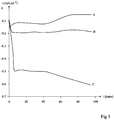
- the figure 3 represents a current characteristic in mA / ml (the milliliters corresponding to the volume of the pellet) as a function of time in days for various biopiles.
- Curve A corresponds to the case where a cellulose acetate membrane was used
- curve B to the case where a Nafion membrane was used
- curve C to the case where a chitosan-based membrane was used such that previously described. It can be seen that the (negative) current is much larger in the case of the chitosan membrane and that the characteristics of the biocell do not degrade, quite the opposite, as a function of time.
- the characteristic starts from a value of -0.15 and fall to a value of the order of -0.05 after about 70 days.
- a Nafion membrane With a Nafion membrane, a relatively constant characteristic is obtained but current densities two to three times lower than with a chitosan-based membrane.
Landscapes
- Chemical & Material Sciences (AREA)
- Chemical Kinetics & Catalysis (AREA)
- Electrochemistry (AREA)
- General Chemical & Material Sciences (AREA)
- Engineering & Computer Science (AREA)
- Life Sciences & Earth Sciences (AREA)
- Health & Medical Sciences (AREA)
- Biochemistry (AREA)
- Manufacturing & Machinery (AREA)
- Materials Engineering (AREA)
- Microbiology (AREA)
- Sustainable Development (AREA)
- Organic Chemistry (AREA)
- Bioinformatics & Cheminformatics (AREA)
- Wood Science & Technology (AREA)
- Zoology (AREA)
- Mechanical Engineering (AREA)
- General Health & Medical Sciences (AREA)
- Sustainable Energy (AREA)
- Hematology (AREA)
- Analytical Chemistry (AREA)
- Genetics & Genomics (AREA)
- General Engineering & Computer Science (AREA)
- Biotechnology (AREA)
- Molecular Biology (AREA)
- Physics & Mathematics (AREA)
- Biomedical Technology (AREA)
- General Physics & Mathematics (AREA)
- Immunology (AREA)
- Pathology (AREA)
- Materials For Medical Uses (AREA)
- Apparatus Associated With Microorganisms And Enzymes (AREA)
- Immobilizing And Processing Of Enzymes And Microorganisms (AREA)
- Carbon And Carbon Compounds (AREA)
Description
- La présente demande de brevet revendique la priorité de la demande de brevet français
FR14/52534 - La présente invention concerne un réacteur implantable in vivo, au niveau duquel est susceptible de se produire une réaction entre des éléments confinés dans ce réacteur et des composés présents dans l'organisme hôte. Cette réaction peut par exemple conduire à une déformation du réacteur, à la génération d'un potentiel électrique, ou à la transformation chimique du composé interagissant avec le réacteur.
- Un réacteur conduisant à la génération d'un potentiel électrique pourra constituer une électrode d'une biopile ou d'un biocapteur, de type à sucre-oxygène, par exemple à glucose-oxygène.
- Un réacteur conduisant à la transformation chimique d'un composé interagissant avec le réacteur constituera par exemple un destructeur de glucose (glucose killer) en transformant par exemple du glucose en un composé qui sera éliminé par l'organisme.
- Bien que l'invention et l'état de la technique soient décrits ici principalement dans le cas de bioélectrodes d'une biopile, on comprendra que l'invention s'applique de façon générale à tout réacteur implantable in vivo.
- Divers types de biopiles à glucose-oxygène sont décrits dans l'art antérieur, par exemple dans la demande de brevet
PCT/FR2009/050639 - L'anode comprend dans une solution une enzyme et un médiateur redox. L'enzyme est apte à catalyser l'oxydation du sucre et est par exemple choisie dans le groupe comprenant glucose-oxydase si le sucre est du glucose et lactose-oxydase si le sucre est du lactose. Le médiateur redox a un potentiel redox bas susceptible d'échanger des électrons avec l'enzyme d'anode et est par exemple choisi dans le groupe comprenant : ubiquinone (UQ) et ferrocène.
- La cathode comprend également dans une solution une enzyme et de préférence un médiateur redox. L'enzyme est apte à catalyser la réduction de l'oxygène et est par exemple choisie dans le groupe comprenant : polyphénol oxydase (PPO), laccase et bilirubine oxydase. Le médiateur redox a un potentiel redox haut susceptible d'échanger des électrons avec l'enzyme de cathode et est par exemple choisi dans le groupe comprenant : hydroquinone (QH2) et 2,2'-azinobis-(3-éthylbenzo-thiazoline-6-sulfonate) (ABTS) .
- Il se produit alors au niveau de l'anode et de la cathode des réactions du type suivant :
- Cathode :

- Anode :

- Cathode :
Q + 2H+ + 2e-→QH2
- Anode :
UQH2→UQ + 2H+ + 2e-
- De telles biopiles fonctionnent convenablement mais, notamment en ce qui concerne la biopile décrite dans la demande de brevet
PCT/FR2009/050639 - En effet, on cherche à implanter de telles biopiles dans des êtres vivants, notamment pour alimenter divers actionneurs, tels que des stimulateurs cardiaques, des sphincters artificiels, ou même des coeurs artificiels.
- On a proposé des biopiles à électrodes solides. Toutefois, des biopiles utilisant de telles électrodes, notamment quand elles sont implantées dans un être vivant, ont présenté une faible durée de vie.
- Une biopile à glucose-oxygène implantable in vivo est décrite notamment dans le brevet européen
EP 2 375 481 de la demanderesse (B10272). Le contenu de ce brevet sera considéré ici comme connu et comme faisant partie intégrante de la présente description. - Dans ce brevet, il est proposé de fabriquer des pastilles d'anode et de cathode d'une biopile à partir d'une compression d'un conducteur tel que du graphite et d'une enzyme auxquels est ajouté un médiateur redox. La cathode et l'anode, ainsi que de préférence l'ensemble de l'anode et de la cathode, sont entourés d'une enceinte semi-perméable, par exemple du type utilisé en dialyse, pour laisser passer le glucose et l'oxygène et ne pas laisser passer les enzymes et les médiateurs redox. Le matériau conducteur à partir duquel sont effectuées la compression d'anode et la compression de cathode est indiqué comme étant du graphite ou un polymère conducteur.
- La
figure 1 ci-jointe reproduit lafigure 2 de ce brevet antérieur. On y voit une pastille d'anode A et une pastille de cathode K solidaires respectivement de conducteurs 1 et 3. L'anode est entourée d'une membrane semi-perméable 11, la cathode d'une membrane semi-perméable 12 et l'ensemble est entouré d'une membrane semi-perméable 13. - Des résultats expérimentaux in vivo satisfaisants ont été obtenus avec les électrodes de biopile décrites dans ce brevet.
- Il est toutefois souhaitable d'améliorer encore la durée de vie des électrodes, c'est-à-dire la durée de fonctionnement de la biopile et d'améliorer au maximum la biocompatibilité de cette pile.
- Plus généralement, il est souhaitable d'améliorer la durée de vie de bioréacteurs tels que définis ci-dessus.
- Les documents
US2011/039164 ,FR2963989 WO2013/130145 et l'article de Holzinger Michael et al. intitulé : « Carbon nanotube/enzyme biofuel cells » Electrochimica acta, vol. 82, 3 mars 2012 concernent diverses réalisations de bioréacteurs. - Ainsi, on prévoit un procédé de fabrication d'un bioréacteur comprenant les étapes suivantes :
- préparer un mélange de poudres dans laquelle la proportion de poudre d'enzyme par rapport à une poudre de nanotubes de carbone est de l'ordre de 50/50 en poids ;
- préparer une solution visqueuse de chitosane dans un rapport de 5 à 15 (en mg) de chitosane à 0,75 à 1,25 (en ml) d'acide acétique dilué à 0,4 à 0,6 % en volume dans de l'eau ;
- ajouter au mélange de poudres la chitosane visqueuse dans une proportion pondérale de 3 à 5 pour la poudre à 5 à 10 pour la chitosane ;
- procéder à une première compression puis à un broyage léger ;
- procéder à une deuxième compression pour réaliser une pastille, la pression appliquée pendant la première et la deuxième compressions étant située dans une plage de 2000 à 6000 kPa; et
- sécher à température ambiante.
- Selon un mode de réalisation, la solution comprend de 0,002 à 0,005 % en masse par volume de génipine.
- Selon un mode de réalisation, la solution comprend de 0,001 à 0,005 % en masse par volume d'acide caféique.
- On prévoit aussi un bioréacteur obtenu par la mise en oeuvre du procédé selon la présente invention.
- On prévoit aussi un bioréacteur dans lequel une membrane poreuse à base de chitosane est posée sur une face active du bioréacteur et collée à la périphérie de celle-ci.
- Selon un mode de réalisation, le bioréacteur constitue une bioélectrode en forme de pastille, dans laquelle un conducteur est collé par l'intermédiaire d'une colle conductrice à la face de la pastille opposée à la face active.
- Selon un mode de réalisation, la membrane comprend des pores d'un diamètre moyen de l'ordre de 1 à 10 nanomètres.
- Selon un mode de réalisation, la membrane comprend une face lisse tournée vers la pastille et une face rugueuse tournée vers l'extérieur.
- On prévoit aussi un bioréacteur selon l'invention, dans lequel la membrane poreuse est obtenue par un procédé comprenant les étapes suivantes :
- préparer une solution dans un rapport de 5 à 15, (en mg) de chitosane à 0,75 à 1,25 (en ml) d'acide acétique dilué à 0,4 à 0,6 % dans de l'eau ;
- agiter ;
- verser sur un support lisse ; et
- sécher pendant une durée de 2 à 4 jours à température ambiante.
- Ces caractéristiques et avantages, ainsi que d'autres, seront exposés en détail dans la description suivante de modes de réalisation particuliers faite à titre non limitatif en relation avec les figures jointes parmi lesquelles :
- la
figure 1 correspond à lafigure 2 du brevet européenEP 2 375 481 ; - les
figures 2A et 2B sont respectivement une vue en coupe et une vue de dessus d'un mode de réalisation d'une électrode ; et - la
figure 3 représente des caractéristiques de courant en fonction du temps de diverses biopiles. - Tout d'abord, on prévoit ici de fabriquer une pastille de bioélectrode non pas à partir de la compression de seulement un conducteur et une enzyme, mais à partir d'une compression de chitosane, d'une enzyme et d'un conducteur et éventuellement d'un médiateur redox et d'autres additifs. Le conducteur peut avantageusement être constitué de nanotubes de carbone multiparois (MWCNT - MultiWalled Carbon NanoTubes).
- On prépare initialement un mélange de poudres d'une enzyme et de nanotubes de carbone, la proportion de poudre d'enzyme par rapport à la poudre de nanotubes de carbone étant de l'ordre de 50/50 en poids, cette proportion pouvant varier d'environ 20 %.
- On prépare également une solution visqueuse de chitosane en ajoutant de la poudre de chitosane dans de l'acide acétique dilué à 0,5 % en volume chauffé à 50°C, et en agitant pendant 2 heures à température ambiante.
- On ajoute au mélange de poudres la chitosane visqueuse dans une proportion pondérale de 2 pour la poudre à 3 pour la chitosane. Pour une pastille on utilisera par exemple 0,04 gramme de poudre et 0,06 gramme de chitosane.
- On réalise un mélange de la poudre et de la chitosane à l'état visqueux et on procède à une première compression puis à un broyage léger. On réalise ensuite une deuxième compression, qui, comme la première compression, est effectuée à une pression choisie dans une plage de 2000 à 6000 kPa pour fournir une pastille, puis on procède à un séchage pendant deux à quatre jours à température ambiante (20 à 30°C) pour que l'ensemble se polymérise.
- On pourra ajouter au mélange initial un agent de réticulation, par exemple de la génipine à 0,0045 % en masse par volume (g/100 ml) dans la solution visqueuse de chitosane après 2h d'agitation. La génipine est préalablement solubilisée dans une solution de 12 % de diméthylsulfoxyde (DMSO) et 88 % d'eau (H2O). On pourra également pour améliorer la résistance de la membrane aux acides ajouter au mélange initial un produit tel que de l'acide caféique dans une proportion de 0,0032 % en masse par volume (g/100 ml) dans la solution visqueuse de chitosane. L'acide caféique est préalablement solubilisé à 4 % dans de l'éthanol. On laisse agiter la solution 30 min avant de prélever 3 g à étaler sur le support lisse pour le séchage comme décrit précédemment.
- Une caractéristique du procédé décrit ici est que, lors de la deuxième compression et du séchage, la chitosane se met en fibres longues interconnectées d'un diamètre d'environ 30 nm. On soulignera le fait qu'un réseau tridimensionnel nanofibreux et nanoporeux est obtenu simplement par compression du polymère avec la poudre et évaporation du solvant à température ambiante. Il en résulte que l'enzyme et les nanotubes de carbone sont immobilisés dans la matrice de fibres de chitosane et ne migrent pas vers l'extérieur de la pastille. Ceci présente un avantage important car l'enzyme, piégée par la matrice de fibres, reste protégée et active pendant une longue durée. De plus, il convient de piéger les nanotubes de carbone, des questions se posant actuellement sur la nocivité éventuelle des nanotubes de carbone in vivo.
- Une biocathode comprenant seulement un conducteur et une enzyme, telle que décrite dans le brevet antérieur susmentionné, présente une stabilité de 1 mois en fonctionnement discontinu. Une biocathode à base de chitosane-MWCNT-laccase, telle que décrite ici, présente une stabilité supérieure à 2 mois en fonctionnement continu. Des mesures in vitro montrent que la stabilité en fonctionnement discontinu de la biocathode décrite ici dépasse les six mois. De plus cette stabilité est aussi assurée in vivo pour une période supérieure à 200 jours. Ceci démontre que la bioélectrode décrite ici offre à l'enzyme un environnement protecteur à son activité mais aussi retient l'enzyme à l'intérieur de la pastille d'électrode et à proximité des nanotubes de carbone pour la conduction électrique. La porosité de la matrice tridimensionnelle de chitosane permet une bonne diffusion des substrats de l'enzyme.
- Le procédé de fabrication des électrodes à base de polymère conducteur et d'enzyme peut être appliqué à la cathode ou à l'anode. Différentes enzymes peuvent être immobilisées dans cette structure : laccase, bilirubine-oxydase, polyphénol-oxydase, glucose-oxydase, glucose-déshydrogénase, catalase, peroxydase.
- Selon un autre aspect de la présente invention, on prévoit une membrane filtrante particulière pour une bioélectrode enzymatique telle que ci-dessus ou toute autre bioélectrode enzymatique obtenue par compression d'un conducteur, d'une enzyme et éventuellement d'un médiateur redox - le médiateur redox n'étant pas indispensable dans la cathode.
- Comme l'illustrent les
figures 2A et 2B , l'électrode se présente sous forme d'une pastille 20 ayant par exemple une forme circulaire en vue de dessus, un diamètre de 0,5 à 1 cm et une épaisseur de 0,5 à 2 mm. Sur la face inférieure de la pastille 20 est fixé un ruban conducteur 22 par exemple par une colle conductrice, par exemple une pâte de carbone 24 elle-même revêtue d'une couche protectrice de colle au silicone 25, choisie parmi des colles biocompatibles. Sur la face supérieure de la pastille 20 est posée - et non pas déposée - une membrane 26 collée à sa périphérie à la pastille par un anneau de colle au silicone 28. - On prévoit ici d'utiliser pour la membrane 26 une membrane à base de chitosane. Cette membrane est par exemple obtenue en partant d'une solution dans un rapport de 5 à 15, par exemple 10 (en mg) de chitosane à 0,75 à 1,25, par exemple 1 (en ml) d'acide acétique dilué à 0,4 à 0,6 % en volume dans de l'eau et chauffé à 50°C. Dans un essai, on a réalisé une dissolution de 200 mg de chitosane dans 20 ml d'acide acétique dilué à 0,5 % en volume dans de l'eau. Ce mélange est agité pendant deux heures. Ensuite, on a prélevé 3 g de ce mélange qu'on a étalé sur un support lisse non adhésif (diamètre 28 cm), par exemple une coupelle de polystyrène antistatique, et séché pendant une durée de 2 à 4 jours à température ambiante, par exemple à une température de 20 à 30°C. Dans un essai, on a séché pendant trois jours à 25°C.
- On obtient ainsi un film nanoporeux flexible. Des expériences effectuées par la demanderesse ont montré que cette flexibilité était liée au fait que le séchage est effectué pendant une longue durée à température ambiante. Cette caractéristique n'est pas obtenue par exemple si l'on utilise des températures de séchage supérieures à 40°C. Pour une épaisseur de film de l'ordre de 7 à 15 pm, par exemple 10 pm, on a obtenu une membrane poreuse avec des diamètres moyens de pores de l'ordre de 1 à 10 nanomètres. On préfèrera se placer dans des conditions où ce diamètre moyen est de l'ordre de 5 à 8 nm pour permettre de laisser passer le glucose et de filtrer les composés de plus grandes dimensions.
- Comme dans le cadre de la réalisation d'une pastille, on pourra ajouter au mélange initial un agent de réticulation, par exemple de la génipine, et un agent de résistance aux acides, par exemple de l'acide caféique.
- Le film obtenu présente une différence de rugosité entre les deux faces qui est due au fait que l'une des faces (la plus rugueuse) a été au contact de l'air et non du support (face lisse). Lors du montage, on placera de préférence la face rugueuse vers l'extérieur par rapport à la surface de la pastille de bioélectrode. En effet, la différence de rugosité sur un film mince influence la diffusion ionique et par conséquent, la résistivité électrique. Les inventeurs ont montré que le film de chitosane présente une bonne conductivité ionique (10-4 S.cm-1). Cette conductivité ionique est meilleure que celle obtenue avec des membranes commerciales telles que le Nafion ou l'acétate de cellulose.
- Le film de chitosane décrit ici permet, par ses propriétés mécaniques notamment sa flexibilité et son taux de gonflement adéquat, de conférer une stabilité mécanique à l'électrode en épousant la surface de la pastille après gonflement de celle-ci dans le liquide. Il confère une interface biocompatible au contact des tissus après implantation de la biopile. Il constitue une barrière efficace contre un éventuel relargage des constituants de l'électrode d'une part, et contre les molécules biologiques venant du liquide extra-cellulaire.
- On pourra régler le diamètre des pores en modifiant : la concentration de la chitosane dans le solvant (acide acétique), le ratio chitosane/agent de réticulation, le poids moléculaire de la chitosane en poudre mis dans la solution initiale d'acide acétique.
- La
figure 3 représente une caractéristique de courant en mA/ml (les millilitres correspondant au volume de la pastille) en fonction du temps en jours pour diverses biopiles. La courbe A correspond au cas où on a utilisé une membrane d'acétate de cellulose, la courbe B au cas où on a utilisé une membrane de Nafion, et la courbe C au cas où on a utilisé une membrane à base de chitosane telle que décrite précédemment. On constate que le courant (négatif) est nettement plus important dans le cas de la membrane à base de chitosane et que les caractéristiques de la biocellule ne se dégradent pas, bien au contraire, en fonction du temps. Par contre, on note que pour l'acétate de cellulose, la caractéristique part d'une valeur de -0,15 et chute à une valeur de l'ordre de -0,05 au bout d'environ 70 jours. Avec une membrane en Nafion, on obtient une caractéristique relativement constante mais des densités de courant deux à trois fois plus faibles qu'avec une membrane à base de chitosane. - Bien que l'invention et l'état de la technique soient décrits ici principalement dans le cas d'une bioélectrode, on comprendra que l'invention s'applique de façon générale à tout bioréacteur implantable in vivo, tel que défini en tête de la présente description.
Claims (9)
- Procédé de fabrication d'un bioréacteur comprenant les étapes suivantes :préparer un mélange de poudres dans laquelle la proportion d'une poudre d'enzyme par rapport à une poudre de nanotubes de carbone est de l'ordre de 50/50 en poids ;préparer une solution visqueuse de chitosane dans un rapport de 5 à 15 (en mg) de chitosane à 0,75 à 1,25 (en ml) d'acide acétique dilué à 0,4 à 0,6 % en volume dans de l'eau ;ajouter au mélange de poudres la chitosane visqueuse dans une proportion pondérale de 3 à 5 pour la poudre à 5 à 10 pour la chitosane ;procéder à une première compression puis à un broyage léger ;procéder à une deuxième compression pour réaliser une pastille, la pression appliquée pendant la première et la deuxième compression étant située dans une plage de 2000 à 6000 kPa ; etsécher à température ambiante.
- Procédé selon la revendication 1, dans lequel la solution comprend de 0,002 à 0,005 % en masse par volume de génipine.
- Procédé selon la revendication 1, dans lequel la solution comprend de 0,001 à 0,005 % en masse par volume d'acide caféique.
- Bioréacteur obtenu par la mise en oeuvre du procédé selon l'une quelconque des revendications 1 à 3.
- Bioréacteur selon la revendication 4, dans lequel une membrane poreuse (26) à base de chitosane est posée sur une face active du bioréacteur et collée à la périphérie de celle-ci.
- Bioréacteur selon la revendication 5 constituant une bioélectrode en forme de pastille (20), dans laquelle un conducteur (22) est collé par l'intermédiaire d'une colle conductrice (24) à la face de la pastille opposée à la face active.
- Bioréacteur selon la revendication 5 ou 6, dans lequel la membrane comprend des pores d'un diamètre moyen de l'ordre de 1 à 10 nanomètres.
- Bioréacteur selon l'une quelconque des revendications 5 à 7, dans lequel la membrane comprend une face lisse tournée vers la pastille et une face rugueuse tournée vers l'extérieur.
- Bioréacteur selon l'une quelconque des revendications 5 à 8, dans lequel la membrane poreuse est obtenue par un procédé comprenant les étapes suivantes :préparer une solution dans un rapport de 5 à 15, (en mg) de chitosane à 0,75 à 1,25 (en ml) d'acide acétique dilué à 0,4 à 0,6 % dans de l'eau ;agiter ;verser sur un support lisse ; etsécher pendant une durée de 2 à 4 jours à température ambiante.
Applications Claiming Priority (2)
| Application Number | Priority Date | Filing Date | Title |
|---|---|---|---|
| FR1452534A FR3019384B1 (fr) | 2014-03-25 | 2014-03-25 | Reacteur implantable biocompatible |
| PCT/FR2015/050725 WO2015145054A2 (fr) | 2014-03-25 | 2015-03-23 | Reacteur implantable biocompatible |
Publications (2)
| Publication Number | Publication Date |
|---|---|
| EP3123544A2 EP3123544A2 (fr) | 2017-02-01 |
| EP3123544B1 true EP3123544B1 (fr) | 2019-06-19 |
Family
ID=51063601
Family Applications (1)
| Application Number | Title | Priority Date | Filing Date |
|---|---|---|---|
| EP15718517.4A Active EP3123544B1 (fr) | 2014-03-25 | 2015-03-23 | Reacteur implantable biocompatible |
Country Status (5)
| Country | Link |
|---|---|
| US (1) | US10316284B2 (fr) |
| EP (1) | EP3123544B1 (fr) |
| CA (1) | CA2943392C (fr) |
| FR (1) | FR3019384B1 (fr) |
| WO (1) | WO2015145054A2 (fr) |
Families Citing this family (7)
| Publication number | Priority date | Publication date | Assignee | Title |
|---|---|---|---|---|
| FR3034307B1 (fr) | 2015-04-03 | 2021-10-22 | Univ Grenoble 1 | Reacteur intestinal implantable |
| WO2017212304A1 (fr) | 2016-06-07 | 2017-12-14 | Universite Grenoble Alpes | Bioélectrode recouverte d'un gel de polysaccharide modifié |
| FR3075831B1 (fr) | 2017-12-22 | 2020-11-13 | Univ Grenoble Alpes | Dispositif implantable de production d'hydrogene |
| FR3086831A1 (fr) * | 2018-10-01 | 2020-04-03 | Orange | Codage et decodage d'une video omnidirectionnelle |
| ES2781376B2 (es) * | 2019-02-28 | 2021-01-27 | Consejo Superior Investigacion | Biosensor inalámbrico, portátil y reutilizable |
| US20230366849A1 (en) * | 2020-09-08 | 2023-11-16 | Technion Research And Development Foundation Ltd. | Oxygen insensitive amperometric biosensors |
| FR3119713B1 (fr) | 2021-02-05 | 2022-12-30 | Univ Grenoble Alpes | Composition pour la fabrication d’électrode, électrode et procédé associé |
Citations (1)
| Publication number | Priority date | Publication date | Assignee | Title |
|---|---|---|---|---|
| US5885609A (en) * | 1997-05-23 | 1999-03-23 | Northeastern University | Biocompatible articles and method for making same |
Family Cites Families (7)
| Publication number | Priority date | Publication date | Assignee | Title |
|---|---|---|---|---|
| ZA827728B (en) * | 1981-11-17 | 1983-08-31 | Nestle Sa | A process for the production of enzymatically active biocatalysts and the products obtained |
| CA2668685A1 (fr) * | 2006-11-06 | 2008-05-15 | Akermin, Inc. | Ensembles empilages de bioanodes et de biocathodes |
| FR2958801B1 (fr) | 2010-04-08 | 2012-05-25 | Univ Joseph Fourier | Biopile a glucose |
| FR2963989B1 (fr) | 2010-08-19 | 2016-03-11 | Univ Joseph Fourier | Biopile a transfert direct |
| WO2012030805A2 (fr) * | 2010-08-30 | 2012-03-08 | President And Fellows Of Harvard College | Matériau composite à base de chitine de grande résistance et son procédé de fabrication |
| US9502730B2 (en) | 2011-11-30 | 2016-11-22 | The Regents Of The University Of California | Printed biofuel cells |
| TWI526534B (zh) * | 2014-12-01 | 2016-03-21 | 國立台灣科技大學 | 葡萄糖氧化酵素/赤血鹽複合電紡聚乙烯醇奈米纖維膜及應用於拋棄式感測試紙的葡萄糖氧化酵素/赤血鹽複合電紡聚乙烯醇奈米纖維膜 |
-
2014
- 2014-03-25 FR FR1452534A patent/FR3019384B1/fr active Active
-
2015
- 2015-03-23 US US15/126,236 patent/US10316284B2/en active Active
- 2015-03-23 CA CA2943392A patent/CA2943392C/fr active Active
- 2015-03-23 WO PCT/FR2015/050725 patent/WO2015145054A2/fr not_active Ceased
- 2015-03-23 EP EP15718517.4A patent/EP3123544B1/fr active Active
Patent Citations (1)
| Publication number | Priority date | Publication date | Assignee | Title |
|---|---|---|---|---|
| US5885609A (en) * | 1997-05-23 | 1999-03-23 | Northeastern University | Biocompatible articles and method for making same |
Also Published As
| Publication number | Publication date |
|---|---|
| CA2943392C (fr) | 2023-08-15 |
| FR3019384B1 (fr) | 2018-01-12 |
| FR3019384A1 (fr) | 2015-10-02 |
| WO2015145054A2 (fr) | 2015-10-01 |
| EP3123544A2 (fr) | 2017-02-01 |
| US20170081626A1 (en) | 2017-03-23 |
| CA2943392A1 (fr) | 2015-10-01 |
| US10316284B2 (en) | 2019-06-11 |
| WO2015145054A3 (fr) | 2016-08-11 |
Similar Documents
| Publication | Publication Date | Title |
|---|---|---|
| CA2943392C (fr) | Reacteur implantable biocompatible | |
| Wang et al. | Oxygen-rich oxidase enzyme electrodes for operation in oxygen-free solutions | |
| CA2721638C (fr) | Biopile a glucose | |
| WO2014135787A1 (fr) | Supercondensateur electrochimique biocompatible | |
| CA3047525C (fr) | Bio-electrode pour la detection et/ou l'oxydation du glucose et son procede de fabrication et dispositif la comprenant | |
| FR3082359A1 (fr) | Biopile a reservoir de biocombustible | |
| CA2808869A1 (fr) | Biopile a transfert direct | |
| EP4111518A1 (fr) | Biopile bi-cathodique à combustible | |
| FR2932603A1 (fr) | Fibres a conductivite electrique pour systemes bioelectrochimiques, electrodes realisees avec de telles fibres et systemes comportant une ou plusieurs de telles electrodes | |
| CA3207400C (fr) | Composition pour la fabrication d'electrode, electrode et procede associe | |
| WO2019122441A1 (fr) | Dispositif implantable de production d'hydrogene | |
| KR20240122800A (ko) | 산화환원 매개체 캡슐화 | |
| El Ichi et al. | Biocompatible implantable biofuel cell | |
| WO2016027020A1 (fr) | Procede de fabrication d'un film conducteur d'un bioreacteur electrochimique | |
| EP4487771A1 (fr) | Dispositif de type patch micro-aiguilles à bioélectrode intégrée | |
| US10522841B2 (en) | Electrochemical reactor block | |
| FR3022694A1 (fr) | Reacteur implantable biocompatible | |
| EP3028334A1 (fr) | Biopile a combustible | |
| EP4416776A2 (fr) | Électrode enzymatique à réservoir intégré | |
| WO2025047806A1 (fr) | Bioélectrode, procédé de production de bioélectrode, dispositif électrochimique, dispositif de mesure de glycémie et procédé de mesure de concentration | |
| WO2026048615A1 (fr) | Électrode métallique poreuse | |
| WO2018091815A1 (fr) | Bioelectrode pour la detection et la mesure de metabolites, et procede de preparation | |
| EP4008034A1 (fr) | Biocathode enzymatique, son procede de fabrication ainsi que biopile a combustible et biocapteur comportant cette biocathode enzymatique | |
| CN1008215B (zh) | 酶电极 | |
| Tingry | Des matériaux moléculaires aux matériaux membranaires bio-inspirés. |
Legal Events
| Date | Code | Title | Description |
|---|---|---|---|
| STAA | Information on the status of an ep patent application or granted ep patent |
Free format text: STATUS: THE INTERNATIONAL PUBLICATION HAS BEEN MADE |
|
| PUAI | Public reference made under article 153(3) epc to a published international application that has entered the european phase |
Free format text: ORIGINAL CODE: 0009012 |
|
| STAA | Information on the status of an ep patent application or granted ep patent |
Free format text: STATUS: REQUEST FOR EXAMINATION WAS MADE |
|
| 17P | Request for examination filed |
Effective date: 20160907 |
|
| AK | Designated contracting states |
Kind code of ref document: A2 Designated state(s): AL AT BE BG CH CY CZ DE DK EE ES FI FR GB GR HR HU IE IS IT LI LT LU LV MC MK MT NL NO PL PT RO RS SE SI SK SM TR |
|
| AX | Request for extension of the european patent |
Extension state: BA ME |
|
| RAP1 | Party data changed (applicant data changed or rights of an application transferred) |
Owner name: UNIVERSITE GRENOBLE ALPES |
|
| DAV | Request for validation of the european patent (deleted) | ||
| DAX | Request for extension of the european patent (deleted) | ||
| STAA | Information on the status of an ep patent application or granted ep patent |
Free format text: STATUS: EXAMINATION IS IN PROGRESS |
|
| 17Q | First examination report despatched |
Effective date: 20171220 |
|
| GRAP | Despatch of communication of intention to grant a patent |
Free format text: ORIGINAL CODE: EPIDOSNIGR1 |
|
| STAA | Information on the status of an ep patent application or granted ep patent |
Free format text: STATUS: GRANT OF PATENT IS INTENDED |
|
| INTG | Intention to grant announced |
Effective date: 20190107 |
|
| GRAS | Grant fee paid |
Free format text: ORIGINAL CODE: EPIDOSNIGR3 |
|
| GRAA | (expected) grant |
Free format text: ORIGINAL CODE: 0009210 |
|
| STAA | Information on the status of an ep patent application or granted ep patent |
Free format text: STATUS: THE PATENT HAS BEEN GRANTED |
|
| AK | Designated contracting states |
Kind code of ref document: B1 Designated state(s): AL AT BE BG CH CY CZ DE DK EE ES FI FR GB GR HR HU IE IS IT LI LT LU LV MC MK MT NL NO PL PT RO RS SE SI SK SM TR |
|
| REG | Reference to a national code |
Ref country code: GB Ref legal event code: FG4D Free format text: NOT ENGLISH |
|
| REG | Reference to a national code |
Ref country code: CH Ref legal event code: EP |
|
| REG | Reference to a national code |
Ref country code: IE Ref legal event code: FG4D Free format text: LANGUAGE OF EP DOCUMENT: FRENCH |
|
| REG | Reference to a national code |
Ref country code: DE Ref legal event code: R096 Ref document number: 602015032246 Country of ref document: DE |
|
| REG | Reference to a national code |
Ref country code: AT Ref legal event code: REF Ref document number: 1146655 Country of ref document: AT Kind code of ref document: T Effective date: 20190715 |
|
| REG | Reference to a national code |
Ref country code: NL Ref legal event code: MP Effective date: 20190619 |
|
| PG25 | Lapsed in a contracting state [announced via postgrant information from national office to epo] |
Ref country code: LT Free format text: LAPSE BECAUSE OF FAILURE TO SUBMIT A TRANSLATION OF THE DESCRIPTION OR TO PAY THE FEE WITHIN THE PRESCRIBED TIME-LIMIT Effective date: 20190619 Ref country code: HR Free format text: LAPSE BECAUSE OF FAILURE TO SUBMIT A TRANSLATION OF THE DESCRIPTION OR TO PAY THE FEE WITHIN THE PRESCRIBED TIME-LIMIT Effective date: 20190619 Ref country code: FI Free format text: LAPSE BECAUSE OF FAILURE TO SUBMIT A TRANSLATION OF THE DESCRIPTION OR TO PAY THE FEE WITHIN THE PRESCRIBED TIME-LIMIT Effective date: 20190619 Ref country code: SE Free format text: LAPSE BECAUSE OF FAILURE TO SUBMIT A TRANSLATION OF THE DESCRIPTION OR TO PAY THE FEE WITHIN THE PRESCRIBED TIME-LIMIT Effective date: 20190619 Ref country code: AL Free format text: LAPSE BECAUSE OF FAILURE TO SUBMIT A TRANSLATION OF THE DESCRIPTION OR TO PAY THE FEE WITHIN THE PRESCRIBED TIME-LIMIT Effective date: 20190619 Ref country code: NO Free format text: LAPSE BECAUSE OF FAILURE TO SUBMIT A TRANSLATION OF THE DESCRIPTION OR TO PAY THE FEE WITHIN THE PRESCRIBED TIME-LIMIT Effective date: 20190919 |
|
| REG | Reference to a national code |
Ref country code: LT Ref legal event code: MG4D |
|
| PG25 | Lapsed in a contracting state [announced via postgrant information from national office to epo] |
Ref country code: LV Free format text: LAPSE BECAUSE OF FAILURE TO SUBMIT A TRANSLATION OF THE DESCRIPTION OR TO PAY THE FEE WITHIN THE PRESCRIBED TIME-LIMIT Effective date: 20190619 Ref country code: GR Free format text: LAPSE BECAUSE OF FAILURE TO SUBMIT A TRANSLATION OF THE DESCRIPTION OR TO PAY THE FEE WITHIN THE PRESCRIBED TIME-LIMIT Effective date: 20190920 Ref country code: RS Free format text: LAPSE BECAUSE OF FAILURE TO SUBMIT A TRANSLATION OF THE DESCRIPTION OR TO PAY THE FEE WITHIN THE PRESCRIBED TIME-LIMIT Effective date: 20190619 Ref country code: BG Free format text: LAPSE BECAUSE OF FAILURE TO SUBMIT A TRANSLATION OF THE DESCRIPTION OR TO PAY THE FEE WITHIN THE PRESCRIBED TIME-LIMIT Effective date: 20190919 |
|
| REG | Reference to a national code |
Ref country code: AT Ref legal event code: MK05 Ref document number: 1146655 Country of ref document: AT Kind code of ref document: T Effective date: 20190619 |
|
| PG25 | Lapsed in a contracting state [announced via postgrant information from national office to epo] |
Ref country code: NL Free format text: LAPSE BECAUSE OF FAILURE TO SUBMIT A TRANSLATION OF THE DESCRIPTION OR TO PAY THE FEE WITHIN THE PRESCRIBED TIME-LIMIT Effective date: 20190619 Ref country code: RO Free format text: LAPSE BECAUSE OF FAILURE TO SUBMIT A TRANSLATION OF THE DESCRIPTION OR TO PAY THE FEE WITHIN THE PRESCRIBED TIME-LIMIT Effective date: 20190619 Ref country code: CZ Free format text: LAPSE BECAUSE OF FAILURE TO SUBMIT A TRANSLATION OF THE DESCRIPTION OR TO PAY THE FEE WITHIN THE PRESCRIBED TIME-LIMIT Effective date: 20190619 Ref country code: EE Free format text: LAPSE BECAUSE OF FAILURE TO SUBMIT A TRANSLATION OF THE DESCRIPTION OR TO PAY THE FEE WITHIN THE PRESCRIBED TIME-LIMIT Effective date: 20190619 Ref country code: PT Free format text: LAPSE BECAUSE OF FAILURE TO SUBMIT A TRANSLATION OF THE DESCRIPTION OR TO PAY THE FEE WITHIN THE PRESCRIBED TIME-LIMIT Effective date: 20191021 Ref country code: AT Free format text: LAPSE BECAUSE OF FAILURE TO SUBMIT A TRANSLATION OF THE DESCRIPTION OR TO PAY THE FEE WITHIN THE PRESCRIBED TIME-LIMIT Effective date: 20190619 Ref country code: SK Free format text: LAPSE BECAUSE OF FAILURE TO SUBMIT A TRANSLATION OF THE DESCRIPTION OR TO PAY THE FEE WITHIN THE PRESCRIBED TIME-LIMIT Effective date: 20190619 |
|
| PG25 | Lapsed in a contracting state [announced via postgrant information from national office to epo] |
Ref country code: ES Free format text: LAPSE BECAUSE OF FAILURE TO SUBMIT A TRANSLATION OF THE DESCRIPTION OR TO PAY THE FEE WITHIN THE PRESCRIBED TIME-LIMIT Effective date: 20190619 Ref country code: SM Free format text: LAPSE BECAUSE OF FAILURE TO SUBMIT A TRANSLATION OF THE DESCRIPTION OR TO PAY THE FEE WITHIN THE PRESCRIBED TIME-LIMIT Effective date: 20190619 Ref country code: IS Free format text: LAPSE BECAUSE OF FAILURE TO SUBMIT A TRANSLATION OF THE DESCRIPTION OR TO PAY THE FEE WITHIN THE PRESCRIBED TIME-LIMIT Effective date: 20191019 |
|
| PG25 | Lapsed in a contracting state [announced via postgrant information from national office to epo] |
Ref country code: TR Free format text: LAPSE BECAUSE OF FAILURE TO SUBMIT A TRANSLATION OF THE DESCRIPTION OR TO PAY THE FEE WITHIN THE PRESCRIBED TIME-LIMIT Effective date: 20190619 |
|
| PG25 | Lapsed in a contracting state [announced via postgrant information from national office to epo] |
Ref country code: DK Free format text: LAPSE BECAUSE OF FAILURE TO SUBMIT A TRANSLATION OF THE DESCRIPTION OR TO PAY THE FEE WITHIN THE PRESCRIBED TIME-LIMIT Effective date: 20190619 Ref country code: PL Free format text: LAPSE BECAUSE OF FAILURE TO SUBMIT A TRANSLATION OF THE DESCRIPTION OR TO PAY THE FEE WITHIN THE PRESCRIBED TIME-LIMIT Effective date: 20190619 |
|
| PG25 | Lapsed in a contracting state [announced via postgrant information from national office to epo] |
Ref country code: IS Free format text: LAPSE BECAUSE OF FAILURE TO SUBMIT A TRANSLATION OF THE DESCRIPTION OR TO PAY THE FEE WITHIN THE PRESCRIBED TIME-LIMIT Effective date: 20200224 |
|
| REG | Reference to a national code |
Ref country code: DE Ref legal event code: R097 Ref document number: 602015032246 Country of ref document: DE |
|
| PLBE | No opposition filed within time limit |
Free format text: ORIGINAL CODE: 0009261 |
|
| STAA | Information on the status of an ep patent application or granted ep patent |
Free format text: STATUS: NO OPPOSITION FILED WITHIN TIME LIMIT |
|
| PG2D | Information on lapse in contracting state deleted |
Ref country code: IS |
|
| 26N | No opposition filed |
Effective date: 20200603 |
|
| PG25 | Lapsed in a contracting state [announced via postgrant information from national office to epo] |
Ref country code: SI Free format text: LAPSE BECAUSE OF FAILURE TO SUBMIT A TRANSLATION OF THE DESCRIPTION OR TO PAY THE FEE WITHIN THE PRESCRIBED TIME-LIMIT Effective date: 20190619 |
|
| PG25 | Lapsed in a contracting state [announced via postgrant information from national office to epo] |
Ref country code: MC Free format text: LAPSE BECAUSE OF FAILURE TO SUBMIT A TRANSLATION OF THE DESCRIPTION OR TO PAY THE FEE WITHIN THE PRESCRIBED TIME-LIMIT Effective date: 20190619 |
|
| REG | Reference to a national code |
Ref country code: BE Ref legal event code: MM Effective date: 20200331 |
|
| PG25 | Lapsed in a contracting state [announced via postgrant information from national office to epo] |
Ref country code: LU Free format text: LAPSE BECAUSE OF NON-PAYMENT OF DUE FEES Effective date: 20200323 |
|
| PG25 | Lapsed in a contracting state [announced via postgrant information from national office to epo] |
Ref country code: IE Free format text: LAPSE BECAUSE OF NON-PAYMENT OF DUE FEES Effective date: 20200323 |
|
| PG25 | Lapsed in a contracting state [announced via postgrant information from national office to epo] |
Ref country code: BE Free format text: LAPSE BECAUSE OF NON-PAYMENT OF DUE FEES Effective date: 20200331 |
|
| PG25 | Lapsed in a contracting state [announced via postgrant information from national office to epo] |
Ref country code: MT Free format text: LAPSE BECAUSE OF FAILURE TO SUBMIT A TRANSLATION OF THE DESCRIPTION OR TO PAY THE FEE WITHIN THE PRESCRIBED TIME-LIMIT Effective date: 20190619 Ref country code: CY Free format text: LAPSE BECAUSE OF FAILURE TO SUBMIT A TRANSLATION OF THE DESCRIPTION OR TO PAY THE FEE WITHIN THE PRESCRIBED TIME-LIMIT Effective date: 20190619 |
|
| REG | Reference to a national code |
Ref country code: DE Ref legal event code: R081 Ref document number: 602015032246 Country of ref document: DE Owner name: UNIVERSITE GRENOBLE ALPES, FR Free format text: FORMER OWNER: UNIVERSITE GRENOBLE ALPES, SAINT-MARTIN-D'HERES, FR |
|
| PG25 | Lapsed in a contracting state [announced via postgrant information from national office to epo] |
Ref country code: MK Free format text: LAPSE BECAUSE OF FAILURE TO SUBMIT A TRANSLATION OF THE DESCRIPTION OR TO PAY THE FEE WITHIN THE PRESCRIBED TIME-LIMIT Effective date: 20190619 |
|
| REG | Reference to a national code |
Ref country code: GB Ref legal event code: 732E Free format text: REGISTERED BETWEEN 20221006 AND 20221012 |
|
| PGFP | Annual fee paid to national office [announced via postgrant information from national office to epo] |
Ref country code: FR Payment date: 20250331 Year of fee payment: 11 |
|
| PGFP | Annual fee paid to national office [announced via postgrant information from national office to epo] |
Ref country code: DE Payment date: 20250430 Year of fee payment: 11 |
|
| PGFP | Annual fee paid to national office [announced via postgrant information from national office to epo] |
Ref country code: GB Payment date: 20250430 Year of fee payment: 11 |
|
| PGFP | Annual fee paid to national office [announced via postgrant information from national office to epo] |
Ref country code: IT Payment date: 20250328 Year of fee payment: 11 |
|
| PGFP | Annual fee paid to national office [announced via postgrant information from national office to epo] |
Ref country code: CH Payment date: 20250501 Year of fee payment: 11 |