EP3123074B1 - System zur speicherung eines unter druck stehenden gases sowie verfahren zum entleeren eines speicherbehälters für ein unter druck stehendes gas - Google Patents
System zur speicherung eines unter druck stehenden gases sowie verfahren zum entleeren eines speicherbehälters für ein unter druck stehendes gas Download PDFInfo
- Publication number
- EP3123074B1 EP3123074B1 EP15706410.6A EP15706410A EP3123074B1 EP 3123074 B1 EP3123074 B1 EP 3123074B1 EP 15706410 A EP15706410 A EP 15706410A EP 3123074 B1 EP3123074 B1 EP 3123074B1
- Authority
- EP
- European Patent Office
- Prior art keywords
- storage container
- emptying
- power source
- vehicle
- external power
- Prior art date
- Legal status (The legal status is an assumption and is not a legal conclusion. Google has not performed a legal analysis and makes no representation as to the accuracy of the status listed.)
- Active
Links
Images
Classifications
-
- F—MECHANICAL ENGINEERING; LIGHTING; HEATING; WEAPONS; BLASTING
- F17—STORING OR DISTRIBUTING GASES OR LIQUIDS
- F17C—VESSELS FOR CONTAINING OR STORING COMPRESSED, LIQUEFIED OR SOLIDIFIED GASES; FIXED-CAPACITY GAS-HOLDERS; FILLING VESSELS WITH, OR DISCHARGING FROM VESSELS, COMPRESSED, LIQUEFIED, OR SOLIDIFIED GASES
- F17C13/00—Details of vessels or of the filling or discharging of vessels
- F17C13/12—Arrangements or mounting of devices for preventing or minimising the effect of explosion ; Other safety measures
-
- F—MECHANICAL ENGINEERING; LIGHTING; HEATING; WEAPONS; BLASTING
- F16—ENGINEERING ELEMENTS AND UNITS; GENERAL MEASURES FOR PRODUCING AND MAINTAINING EFFECTIVE FUNCTIONING OF MACHINES OR INSTALLATIONS; THERMAL INSULATION IN GENERAL
- F16K—VALVES; TAPS; COCKS; ACTUATING-FLOATS; DEVICES FOR VENTING OR AERATING
- F16K31/00—Actuating devices; Operating means; Releasing devices
- F16K31/02—Actuating devices; Operating means; Releasing devices electric; magnetic
- F16K31/025—Actuating devices; Operating means; Releasing devices electric; magnetic actuated by thermo-electric means
-
- F—MECHANICAL ENGINEERING; LIGHTING; HEATING; WEAPONS; BLASTING
- F17—STORING OR DISTRIBUTING GASES OR LIQUIDS
- F17C—VESSELS FOR CONTAINING OR STORING COMPRESSED, LIQUEFIED OR SOLIDIFIED GASES; FIXED-CAPACITY GAS-HOLDERS; FILLING VESSELS WITH, OR DISCHARGING FROM VESSELS, COMPRESSED, LIQUEFIED, OR SOLIDIFIED GASES
- F17C7/00—Methods or apparatus for discharging liquefied, solidified, or compressed gases from pressure vessels, not covered by another subclass
-
- F—MECHANICAL ENGINEERING; LIGHTING; HEATING; WEAPONS; BLASTING
- F17—STORING OR DISTRIBUTING GASES OR LIQUIDS
- F17C—VESSELS FOR CONTAINING OR STORING COMPRESSED, LIQUEFIED OR SOLIDIFIED GASES; FIXED-CAPACITY GAS-HOLDERS; FILLING VESSELS WITH, OR DISCHARGING FROM VESSELS, COMPRESSED, LIQUEFIED, OR SOLIDIFIED GASES
- F17C2201/00—Vessel construction, in particular geometry, arrangement or size
- F17C2201/05—Size
- F17C2201/056—Small (<1 m3)
-
- F—MECHANICAL ENGINEERING; LIGHTING; HEATING; WEAPONS; BLASTING
- F17—STORING OR DISTRIBUTING GASES OR LIQUIDS
- F17C—VESSELS FOR CONTAINING OR STORING COMPRESSED, LIQUEFIED OR SOLIDIFIED GASES; FIXED-CAPACITY GAS-HOLDERS; FILLING VESSELS WITH, OR DISCHARGING FROM VESSELS, COMPRESSED, LIQUEFIED, OR SOLIDIFIED GASES
- F17C2205/00—Vessel construction, in particular mounting arrangements, attachments or identifications means
- F17C2205/03—Fluid connections, filters, valves, closure means or other attachments
- F17C2205/0302—Fittings, valves, filters, or components in connection with the gas storage device
- F17C2205/0311—Closure means
- F17C2205/0317—Closure means fusing or melting
-
- F—MECHANICAL ENGINEERING; LIGHTING; HEATING; WEAPONS; BLASTING
- F17—STORING OR DISTRIBUTING GASES OR LIQUIDS
- F17C—VESSELS FOR CONTAINING OR STORING COMPRESSED, LIQUEFIED OR SOLIDIFIED GASES; FIXED-CAPACITY GAS-HOLDERS; FILLING VESSELS WITH, OR DISCHARGING FROM VESSELS, COMPRESSED, LIQUEFIED, OR SOLIDIFIED GASES
- F17C2205/00—Vessel construction, in particular mounting arrangements, attachments or identifications means
- F17C2205/03—Fluid connections, filters, valves, closure means or other attachments
- F17C2205/0302—Fittings, valves, filters, or components in connection with the gas storage device
- F17C2205/0323—Valves
- F17C2205/0332—Safety valves or pressure relief valves
-
- F—MECHANICAL ENGINEERING; LIGHTING; HEATING; WEAPONS; BLASTING
- F17—STORING OR DISTRIBUTING GASES OR LIQUIDS
- F17C—VESSELS FOR CONTAINING OR STORING COMPRESSED, LIQUEFIED OR SOLIDIFIED GASES; FIXED-CAPACITY GAS-HOLDERS; FILLING VESSELS WITH, OR DISCHARGING FROM VESSELS, COMPRESSED, LIQUEFIED, OR SOLIDIFIED GASES
- F17C2221/00—Handled fluid, in particular type of fluid
- F17C2221/01—Pure fluids
- F17C2221/012—Hydrogen
-
- F—MECHANICAL ENGINEERING; LIGHTING; HEATING; WEAPONS; BLASTING
- F17—STORING OR DISTRIBUTING GASES OR LIQUIDS
- F17C—VESSELS FOR CONTAINING OR STORING COMPRESSED, LIQUEFIED OR SOLIDIFIED GASES; FIXED-CAPACITY GAS-HOLDERS; FILLING VESSELS WITH, OR DISCHARGING FROM VESSELS, COMPRESSED, LIQUEFIED, OR SOLIDIFIED GASES
- F17C2221/00—Handled fluid, in particular type of fluid
- F17C2221/03—Mixtures
- F17C2221/032—Hydrocarbons
- F17C2221/033—Methane, e.g. natural gas, CNG, LNG, GNL, GNC, PLNG
-
- F—MECHANICAL ENGINEERING; LIGHTING; HEATING; WEAPONS; BLASTING
- F17—STORING OR DISTRIBUTING GASES OR LIQUIDS
- F17C—VESSELS FOR CONTAINING OR STORING COMPRESSED, LIQUEFIED OR SOLIDIFIED GASES; FIXED-CAPACITY GAS-HOLDERS; FILLING VESSELS WITH, OR DISCHARGING FROM VESSELS, COMPRESSED, LIQUEFIED, OR SOLIDIFIED GASES
- F17C2223/00—Handled fluid before transfer, i.e. state of fluid when stored in the vessel or before transfer from the vessel
- F17C2223/01—Handled fluid before transfer, i.e. state of fluid when stored in the vessel or before transfer from the vessel characterised by the phase
- F17C2223/0107—Single phase
- F17C2223/0123—Single phase gaseous, e.g. CNG, GNC
-
- F—MECHANICAL ENGINEERING; LIGHTING; HEATING; WEAPONS; BLASTING
- F17—STORING OR DISTRIBUTING GASES OR LIQUIDS
- F17C—VESSELS FOR CONTAINING OR STORING COMPRESSED, LIQUEFIED OR SOLIDIFIED GASES; FIXED-CAPACITY GAS-HOLDERS; FILLING VESSELS WITH, OR DISCHARGING FROM VESSELS, COMPRESSED, LIQUEFIED, OR SOLIDIFIED GASES
- F17C2223/00—Handled fluid before transfer, i.e. state of fluid when stored in the vessel or before transfer from the vessel
- F17C2223/03—Handled fluid before transfer, i.e. state of fluid when stored in the vessel or before transfer from the vessel characterised by the pressure level
- F17C2223/036—Very high pressure (>80 bar)
-
- F—MECHANICAL ENGINEERING; LIGHTING; HEATING; WEAPONS; BLASTING
- F17—STORING OR DISTRIBUTING GASES OR LIQUIDS
- F17C—VESSELS FOR CONTAINING OR STORING COMPRESSED, LIQUEFIED OR SOLIDIFIED GASES; FIXED-CAPACITY GAS-HOLDERS; FILLING VESSELS WITH, OR DISCHARGING FROM VESSELS, COMPRESSED, LIQUEFIED, OR SOLIDIFIED GASES
- F17C2250/00—Accessories; Control means; Indicating, measuring or monitoring of parameters
- F17C2250/04—Indicating or measuring of parameters as input values
- F17C2250/0404—Parameters indicated or measured
- F17C2250/043—Pressure
-
- F—MECHANICAL ENGINEERING; LIGHTING; HEATING; WEAPONS; BLASTING
- F17—STORING OR DISTRIBUTING GASES OR LIQUIDS
- F17C—VESSELS FOR CONTAINING OR STORING COMPRESSED, LIQUEFIED OR SOLIDIFIED GASES; FIXED-CAPACITY GAS-HOLDERS; FILLING VESSELS WITH, OR DISCHARGING FROM VESSELS, COMPRESSED, LIQUEFIED, OR SOLIDIFIED GASES
- F17C2250/00—Accessories; Control means; Indicating, measuring or monitoring of parameters
- F17C2250/04—Indicating or measuring of parameters as input values
- F17C2250/0404—Parameters indicated or measured
- F17C2250/0439—Temperature
-
- F—MECHANICAL ENGINEERING; LIGHTING; HEATING; WEAPONS; BLASTING
- F17—STORING OR DISTRIBUTING GASES OR LIQUIDS
- F17C—VESSELS FOR CONTAINING OR STORING COMPRESSED, LIQUEFIED OR SOLIDIFIED GASES; FIXED-CAPACITY GAS-HOLDERS; FILLING VESSELS WITH, OR DISCHARGING FROM VESSELS, COMPRESSED, LIQUEFIED, OR SOLIDIFIED GASES
- F17C2260/00—Purposes of gas storage and gas handling
- F17C2260/03—Dealing with losses
- F17C2260/035—Dealing with losses of fluid
- F17C2260/037—Handling leaked fluid
-
- F—MECHANICAL ENGINEERING; LIGHTING; HEATING; WEAPONS; BLASTING
- F17—STORING OR DISTRIBUTING GASES OR LIQUIDS
- F17C—VESSELS FOR CONTAINING OR STORING COMPRESSED, LIQUEFIED OR SOLIDIFIED GASES; FIXED-CAPACITY GAS-HOLDERS; FILLING VESSELS WITH, OR DISCHARGING FROM VESSELS, COMPRESSED, LIQUEFIED, OR SOLIDIFIED GASES
- F17C2260/00—Purposes of gas storage and gas handling
- F17C2260/04—Reducing risks and environmental impact
- F17C2260/042—Reducing risk of explosion
-
- F—MECHANICAL ENGINEERING; LIGHTING; HEATING; WEAPONS; BLASTING
- F17—STORING OR DISTRIBUTING GASES OR LIQUIDS
- F17C—VESSELS FOR CONTAINING OR STORING COMPRESSED, LIQUEFIED OR SOLIDIFIED GASES; FIXED-CAPACITY GAS-HOLDERS; FILLING VESSELS WITH, OR DISCHARGING FROM VESSELS, COMPRESSED, LIQUEFIED, OR SOLIDIFIED GASES
- F17C2270/00—Applications
- F17C2270/01—Applications for fluid transport or storage
- F17C2270/0165—Applications for fluid transport or storage on the road
- F17C2270/0168—Applications for fluid transport or storage on the road by vehicles
- F17C2270/0178—Cars
-
- Y—GENERAL TAGGING OF NEW TECHNOLOGICAL DEVELOPMENTS; GENERAL TAGGING OF CROSS-SECTIONAL TECHNOLOGIES SPANNING OVER SEVERAL SECTIONS OF THE IPC; TECHNICAL SUBJECTS COVERED BY FORMER USPC CROSS-REFERENCE ART COLLECTIONS [XRACs] AND DIGESTS
- Y02—TECHNOLOGIES OR APPLICATIONS FOR MITIGATION OR ADAPTATION AGAINST CLIMATE CHANGE
- Y02E—REDUCTION OF GREENHOUSE GAS [GHG] EMISSIONS, RELATED TO ENERGY GENERATION, TRANSMISSION OR DISTRIBUTION
- Y02E60/00—Enabling technologies; Technologies with a potential or indirect contribution to GHG emissions mitigation
- Y02E60/30—Hydrogen technology
- Y02E60/32—Hydrogen storage
-
- Y—GENERAL TAGGING OF NEW TECHNOLOGICAL DEVELOPMENTS; GENERAL TAGGING OF CROSS-SECTIONAL TECHNOLOGIES SPANNING OVER SEVERAL SECTIONS OF THE IPC; TECHNICAL SUBJECTS COVERED BY FORMER USPC CROSS-REFERENCE ART COLLECTIONS [XRACs] AND DIGESTS
- Y10—TECHNICAL SUBJECTS COVERED BY FORMER USPC
- Y10T—TECHNICAL SUBJECTS COVERED BY FORMER US CLASSIFICATION
- Y10T137/00—Fluid handling
- Y10T137/1842—Ambient condition change responsive
- Y10T137/1939—Atmospheric
- Y10T137/1963—Temperature
-
- Y—GENERAL TAGGING OF NEW TECHNOLOGICAL DEVELOPMENTS; GENERAL TAGGING OF CROSS-SECTIONAL TECHNOLOGIES SPANNING OVER SEVERAL SECTIONS OF THE IPC; TECHNICAL SUBJECTS COVERED BY FORMER USPC CROSS-REFERENCE ART COLLECTIONS [XRACs] AND DIGESTS
- Y10—TECHNICAL SUBJECTS COVERED BY FORMER USPC
- Y10T—TECHNICAL SUBJECTS COVERED BY FORMER US CLASSIFICATION
- Y10T137/00—Fluid handling
- Y10T137/1842—Ambient condition change responsive
- Y10T137/1939—Atmospheric
- Y10T137/1963—Temperature
- Y10T137/1987—With additional diverse control
Definitions
- the invention relates to a system for storing a pressurized gas in a motor vehicle, comprising a storage container and at least one thermally activatable safety valve for emptying the storage container, which activates itself in the presence of a corresponding high temperature. Furthermore, the invention relates to a method for emptying a storage container for a pressurized gas in a motor vehicle.
- these storage tanks are also equipped with thermally activated safety valves (Thermal Pressure Relief Devices, TPRD), which activate themselves in the presence of a correspondingly high temperature, for example by a sealing compound melts. So it can be achieved that the compressed gas storage tank emptied before it bursts due to the excessive internal pressure.
- TPRD Thermally activated safety valves
- the storage container for example in an accident, is pre-damaged.
- the bursting pressure of the storage container can be lowered below the operating pressure or at least below the release pressure of the provided safety devices, so that the damaged container poses a potential safety risk while it is still under pressure.
- a compressed gas storage tank usually has so-called service valves, via which a manual emptying is possible, however These may be located at a hard to reach place on the vehicle or difficult to access due to the present accident. Even a possibly provided service function for relieving pressure via a so-called service port can no longer be available in the event of an accident due to omission of the vehicle electrical system.
- the WO / 2004/014683 A1 shows a safety device for motor vehicles.
- an active safety system which triggers, for example, an airbag, transmits an activation signal to an emptying device.
- an explosive charge is ignited, which can be arranged in the region of a thermally activated safety valve, and thus empties the storage container.
- This also addresses the possibility of igniting the explosive charge by radio from outside the vehicle, with a radio transmitter carried by rescue personnel sends a signal to the vehicle security system, which then generates the activation signal to the emptying device.
- a disadvantage of the described embodiment is that in an accidental failure of the vehicle electronics this possibility of targeted emptying of the compressed gas storage tank is no longer given.
- the invention in contrast, provides a system for storing a pressurized gas in a motor vehicle or a method for emptying a storage container for a pressurized gas, in which, if necessary, a targeted emptying of the pressurized gas storage container is reliably possible.
- an additional, activatable emptying device for the storage container which has an interface for an external energy source, to which the external energy source can be connected deliberately empty the storage tank.
- the additional emptying device comprises a triggering device provided on the thermally activated safety valve, to the interface of which the external energy source can be connected in order to trigger the safety valve in a targeted manner.
- a triggering device provided on the thermally activated safety valve, to the interface of which the external energy source can be connected in order to trigger the safety valve in a targeted manner.
- an additional valve as an emptying device, which is arranged parallel to the thermally activatable safety valve and is activated by means of the external energy source.
- the interface preferably has connections, in particular electrical connections, for the external energy source, which are arranged in an externally accessible area of the motor vehicle. This makes it possible, for example, rescue workers after an accident to deliberately empty the compressed gas in the storage container in order to prevent later rupture of the storage container, for example when the vehicle is being transported away.
- the external energy source can be activated externally after connection to the emptying device in order to empty the storage container. In this way, the time of emptying can be precisely determined and deliberately delayed.
- the activation is carried out remotely, in particular via radio or an electric ignition line. This allows the vehicle owner and other persons present to first bring to a safe distance from the vehicle before the storage container is specifically emptied.
- the emptying device comprises a triggering device provided on the safety valve
- the triggering device preferably has one thermal actuator, in particular an electric heater, on. This may for example be designed as a heating resistor and must be dimensioned so that the triggering temperature of the thermally activated safety valve (about 105-110 ° C) is reached, but not the ignition temperature of the gas.
- the triggering device on a heating coil with which the thermally activated safety valve is at least partially wrapped.
- the safety valve can be wrapped as a whole, or it is only one associated with the safety valve glass ampoule wrapped with the heating coil and optionally isolated, this of course with a combustible material to ensure functionality in case of fire.
- the heating coil could be integrated into a wall of a glass ampoule provided at the thermally activatable safety valve. In the latter two cases, less energy is needed to activate the safety valve.
- the emptying device comprises a mechanical or a pyrotechnic actuator.
- a mechanical actuator is a piezoactuator which, when activated, destroys a glass ampule of the safety valve.
- connections for the external energy source can be arranged in an interior of the motor vehicle.
- the emptying device may have an open during normal driving interruption switch, which is closed by a crash signal of a vehicle safety system. Even then it is ensured that the emptying device can be activated only when necessary, namely after an accident.
- the pressurized gas is, in particular, hydrogen or natural gas, preferably compressed natural gas (so-called compressed natural gas, CNG).
- the object mentioned at the outset is likewise achieved by a method for emptying a storage container for a gas under pressure in a motor vehicle, which in particular is in a system of the previously described Art applies.
- the method according to the invention has the following steps: an external energy source is connected to an emptying device provided on the storage container, if necessary, and the external energy source is activated in order to purposely emptying the storage container via the emptying device actuated thereby.
- the inventive method is characterized in that the storage container is emptied only when needed and delayed. Vehicle occupants can thus be recovered only before gas escapes, which could ignite when emptying.
- the provision of the energy required for the emptying device by an external energy source also ensures that the emptying of the storage container can also take place when an in-vehicle power supply fails.
- the emptying device comprises a triggering device, which is provided on a thermally activatable safety valve for emptying the storage container, which activates itself in the presence of a correspondingly high temperature.
- the external energy source is activated in order to trigger the safety valve in a targeted manner.
- the already existing thermally activated safety valve is used to allow a targeted demand-oriented emptying of the storage container.
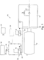
- the sole figure shows a system 10 for storing a pressurized gas in a motor vehicle, wherein the gas is in particular hydrogen or natural gas.
- the system 10 comprises a pressurized gas storage vessel 12 to which a tank valve 14 is provided to remove the gas, e.g. to supply to an engine.
- the tank valve 14 comprises various valves and temperature or pressure sensors, which are combined in the tank valve 14. Since the tank valve 14 is known per se and beyond its exact operation is not relevant to the present invention, a detailed description is omitted here.
- the system 10 has two mutually parallel, thermally activatable safety valves 16, 18 (also referred to as TPRD), which are coupled via a line 20 and the tank valve 14 to the storage container 12.
- TPRD thermally activatable safety valves 16, 18
- the safety valves 16, 18 may, for example, have a sealing compound which is arranged in a flow path of the gas. At a correspondingly high temperature of about 105-110 ° C in the range of one of the safety valves 16, 18, the mass melts, and the respective safety valve 16, 18 is permeable to the gas stored in the storage tank 12, thus activating itself in this way. Thus, in a fire, the pressurized gas is discharged from the storage tank 12.
- the safety valves 16, 18 may comprise a fluid-filled glass ampule bursting at a correspondingly high temperature and allowing the gas to escape from the reservoir 12.
- a release device 22 is present at the safety valve 16, which forms an additional, activatable emptying device for the storage container 12.
- the triggering device 22 comprises in the embodiment shown a thermal actuator in the form of an electric heater 24, which is arranged on the safety valve 16 and is designed here as a heating resistor.
- the triggering device 22 furthermore has an interface 26, which comprises electrical connections 28 for an external energy source 30.
- the interface 26 or the connections 28 are arranged in an easily accessible area of the motor vehicle, in particular in an externally accessible area of the motor vehicle.
- the external power source 30 is connected to the interface 26, more precisely the terminals 28, the trigger device 22 and, after Any persons could be brought to safety, specifically activated externally, in particular by radio or an electric ignition (indicated in the figure by Pos. 31). After activation of the external energy source 30, current flows through the heater 24 and this heats up to a temperature which is sufficient to trigger the safety valve 16 targeted and thus to empty the storage container 12.
- the emptying or triggering device 22 may have an open during normal driving interrupt switch 32, which is closed only by a crash signal of a vehicle safety system 34.
- the terminals 28 may be arranged in an interior of the motor vehicle.
- the emptying or triggering device 22 may comprise a mechanical or pyrotechnic actuator which, upon activation, e.g. destroyed a glass ampule of the safety valve 16.
- the storage container 12 is thus specifically emptied after an accident on site, whereby a bursting of the container during salvage operations, transport or storage after the accident (ie not in immediate temporal proximity to the accident event) can be prevented. Since, when emptying the storage container 12, especially in the case of hydrogen, there is the danger that the gas will ignite, the location of the accident should be evacuated before emptying. In addition, ignition sources should be avoided and the measure should not be carried out indoors, under bridges or in tunnels.
Landscapes
- Engineering & Computer Science (AREA)
- General Engineering & Computer Science (AREA)
- Mechanical Engineering (AREA)
- Filling Or Discharging Of Gas Storage Vessels (AREA)
- Air Bags (AREA)
- Emergency Lowering Means (AREA)
Description
- Die Erfindung betrifft ein System zur Speicherung eines unter Druck stehenden Gases in einem Kraftfahrzeug, mit einem Speicherbehälter und wenigstens einem thermisch aktivierbaren Sicherheitsventil zur Entleerung des Speicherbehälters, welches sich bei Vorliegen einer entsprechenden hohen Temperatur selbst aktiviert. Weiterhin betrifft die Erfindung ein Verfahren zum Entleeren eines Speicherbehälters für ein unter Druck stehendes Gas in einem Kraftfahrzeug.
- Im Zuge alternativer Antriebskonzepte werden zunehmend Fahrzeuge entwickelt, die mit Gas, etwa Erdgas oder Wasserstoff, betrieben werden. Derartige Fahrzeuge benötigen einen Speicherbehälter für das unter hohem Druck stehende Gas sowie gewisse Sicherheitseinrichtungen, die dafür Sorge tragen, dass der im Speicherbehälter herrschende Druck den Berstdruck des Behälters nicht erreicht, um ein Bersten des Speicherbehälters zu verhindern.
- Für den Brandfall sind diese Speicherbehälter zudem mit thermisch aktivierbaren Sicherheitsventilen (Thermal Pressure Relief Devices, TPRD) ausgestattet, die sich bei Vorliegen einer entsprechend hohen Temperatur selbst aktivieren, beispielsweise indem eine Verschlussmasse aufschmilzt. So kann erreicht werden, dass sich der Druckgas-Speicherbehälter entleert, ehe er aufgrund des zu hohen Innendrucks birst.
- Nun ist es denkbar, dass der Speicherbehälter, beispielsweise bei einem Unfall, vorgeschädigt wird. Dadurch kann der Berstdruck des Speicherbehälters unter den Betriebsdruck abgesenkt werden oder zumindest unter den Auslösedruck der vorgesehenen Sicherheitseinrichtungen, so dass der beschädigte Behälter ein potentielles Sicherheitsrisiko darstellt, solange er noch unter Druck steht. Zwar weist ein solcher Druckgas-Speicherbehälter üblicherweise sogenannte Serviceventile auf, über die eine manuelle Entleerung möglich ist, jedoch sind diese unter Umständen an einer schwer erreichbaren Stelle am Fahrzeug angeordnet oder durch den vorliegenden Unfall schwer zugänglich. Auch eine eventuell vorgesehene Servicefunktion zum Druckentlasten über einen sogenannten Service-Port kann bei einem Unfall durch Wegfall des Bordnetzes nicht länger verfügbar sein.
- Es ist daher oftmals nicht möglich, nach einem Unfall den Speicherbehälter gezielt zu entleeren und das System somit in einen stabilen Zustand zu versetzen.
- Die
WO/2004/014683 A1 zeigt eine Sicherheitsvorrichtung für Kraftfahrzeuge.Aus derDE 10 2010 006 516 A1 ist ein gattungsgemäßes System zur Speicherung eines unter Druck stehenden Gases in einem Fahrzeug bekannt, bei dem im Falle eines Unfalls ein aktives Sicherheitssystem, welches beispielsweise auch einen Airbag auslöst, ein Aktivierungssignal an eine Entleerungseinrichtung übermittelt. Durch das Aktivierungssignal wird eine Sprengladung gezündet, die im Bereich eines thermisch aktivierbaren Sicherheitsventils angeordnet sein kann, und so den Speicherbehälter entleert. Hierbei wird auch die Möglichkeit angesprochen, die Sprengladung über Funk von außerhalb des Fahrzeugs zu zünden, wobei ein von Rettungskräften mitgeführter Funksender ein Signal an das Fahrzeug-Sicherheitssystem sendet, welches dann das Aktivierungssignal an die Entleerungseinrichtung generiert. - Nachteilig bei der beschriebenen Ausgestaltung ist, dass bei einem unfallbedingten Ausfallen der Fahrzeugelektronik diese Möglichkeit der gezielten Entleerung des Druckgas-Speicherbehälters nicht länger gegeben ist.
- Die Erfindung schafft demgegenüber ein System zur Speicherung eines unter Druck stehenden Gases in einem Kraftfahrzeug bzw. ein Verfahren zum Entleeren eines Speicherbehälters für ein unter Druck stehendes Gas, bei dem im Bedarfsfall zuverlässig eine gezielte Entleerung des Druckgas-Speicherbehälters möglich ist.
- Gemäß einem ersten Aspekt der Erfindung ist dazu bei einem System der eingangs genannten Art eine zusätzliche, aktivierbare Entleerungsvorrichtung für den Speicherbehälter vorgesehen, die eine Schnittstelle für eine externe Energiequelle hat, an die die externe Energiequelle angeschlossen werden kann, um den Speicherbehälter gezielt zu entleeren. Somit ist es möglich, nach einem Unfall durch Anschließen einer externen (also nicht zum Fahrzeug gehörigen) Energiequelle unabhängig von der Funktionstüchtigkeit der Fahrzeugelektronik die benötigte Energie bereitzustellen, um mithilfe der aktivierbaren Entleerungsvorrichtung den Speicherbehälter gezielt zu entleeren.
- Gemäß einer bevorzugten Ausführungsform der Erfindung umfasst die zusätzliche Entleerungsvorrichtung eine am thermisch aktivierbaren Sicherheitsventil vorgesehene Auslösevorrichtung, an deren Schnittstelle die externe Energiequelle angeschlossen werden kann, um das Sicherheitsventil gezielt auszulösen. Es wird also das ohnehin vorhandene thermisch aktivierbare Sicherheitsventil genutzt, welches nach Anschließen der externen Energiequelle gezielt ausgelöst wird und so den Speicherbehälter entleert. Auf diese Weise erhält man eine einfache und somit kostengünstige Ausgestaltung.
- Alternativ wäre es denkbar, ein zusätzliches Ventil als Entleerungsvorrichtung vorzusehen, welches parallel zum thermisch aktivierbaren Sicherheitsventil angeordnet ist und mittels der externen Energiequelle aktiviert wird.
- Vorzugsweise weist die Schnittstelle Anschlüsse, insbesondere elektrische Anschlüsse, für die externe Energiequelle auf, die in einem von außen zugänglichen Bereich des Kraftfahrzeugs angeordnet sind. Dies ermöglicht es zum Beispiel Rettungskräften nach einem Unfall, das Druckgas im Speicherbehälter gezielt zu entleeren, um ein späteres Bersten des Speicherbehälters, etwa beim Abtransport des Fahrzeugs, zu verhindern.
- In einer Weiterbildung der Erfindung kann die externe Energiequelle nach Anschließen an die Entleerungsvorrichtung von extern aktiviert werden, um den Speicherbehälter zu entleeren. Auf diese Weise lässt sich der Zeitpunkt des Entleerens exakt bestimmen und gezielt verzögern.
- Vorzugsweise erfolgt dabei die Aktivierung ferngesteuert, insbesondere über Funk oder eine elektrische Zündleitung. Dies ermöglicht es dem Fahrzeughalter und weiteren anwesenden Personen, sich zunächst in einen sicheren Abstand vom Fahrzeug zu bringen, bevor der Speicherbehälter gezielt entleert wird.
- Im Falle, dass die Entleerungsvorrichtung eine am Sicherheitsventil vorgesehene Auslösevorrichtung umfasst, weist die Auslösevorrichtung bevorzugt einen thermischen Aktuator, insbesondere eine elektrische Heizung, auf. Diese kann z.B. als Heizwiderstand ausgebildet sein und muss so dimensioniert sein, dass die Auslösetemperatur des thermisch aktivierbaren Sicherheitsventils (ca. 105-110°C) erreicht wird, nicht jedoch die Zündtemperatur des Gases.
- In einer konstruktiv einfachen Ausgestaltung weist die Auslösevorrichtung eine Heizspirale auf, mit der das thermisch aktivierbare Sicherheitsventil zumindest teilweise umwickelt ist. Dabei kann das Sicherheitsventil als Ganzes umwickelt sein, oder es ist lediglich eine zum Sicherheitsventil gehörige Glasampulle mit der Heizspirale umwickelt und gegebenenfalls isoliert, dies natürlich mit einem brennbaren Material, um die Funktionalität im Brandfall zu gewährleisten. Ebenso könnte die Heizspirale in eine Wand einer beim thermisch aktivierbaren Sicherheitsventil vorgesehenen Glasampulle integriert sein. In den beiden letztgenannten Fällen wird weniger Energie benötigt, um das Sicherheitsventil zu aktivieren.
- In einer alternativen Ausgestaltung umfasst die Entleerungsvorrichtung einen mechanischen oder einen pyrotechnischen Aktuator. Ein Beispiel für einen mechanischen Aktuator ist ein Piezoaktuator, der bei Aktivierung eine Glasampulle des Sicherheitsventils zerstört.
- Um einem möglichen Missbrauch vorzubeugen, können die Anschlüsse für die externe Energiequelle in einem Innenraum des Kraftfahrzeugs angeordnet sein.
- Alternativ oder zusätzlich kann die Entleerungsvorrichtung einen im normalen Fahrbetrieb offenen Unterbrechungsschalter aufweisen, der durch ein Crashsignal eines Fahrzeugsicherheitssystems geschlossen wird. Auch dann ist gewährleistet, dass sich die Entleerungsvorrichtung nur im Bedarfsfall, nämlich nach einem Unfall, aktivieren lässt.
- Wie bereits eingangs erwähnt, handelt es sich bei dem unter Druck stehenden Gas insbesondere um Wasserstoff oder Erdgas, vorzugsweise komprimiertes Erdgas (sogenanntes Compressed Natural Gas, CNG).
- Die eingangs genannte Aufgabe wird ebenfalls gelöst durch ein Verfahren zum Entleeren eines Speicherbehälters für ein unter Druck stehendes Gas in einem Kraftfahrzeug, welches insbesondere in einem System der bisher beschriebenen Art Anwendung findet. Das erfindungsgemäße Verfahren weist dabei die folgenden Schritte auf: an eine an dem Speicherbehälter vorgesehene Entleerungsvorrichtung wird im Bedarfsfall eine externe Energiequelle angeschlossen, und die externe Energiequelle wird aktiviert, um über die dadurch betätigte Entleerungsvorrichtung den Speicherbehälter gezielt zu entleeren.
- Unter Bedarfsfall ist auch hier z.B. ein Unfall zu verstehen. Im Gegensatz zu einer unmittelbaren Aktivierung der Entleerungsvorrichtung durch das Unfallereignis selbst, etwa mittels eines aktiven Fahrzeug-Sicherheitssystems, zeichnet sich das erfindungsgemäße Verfahren dadurch aus, dass der Speicherbehälter nur bei Bedarf und zeitlich verzögert entleert wird. Fahrzeuginsassen können somit erst geborgen werden, bevor Gas austritt, das sich beim Entleeren entzünden könnte. Die Bereitstellung der für die Entleerungsvorrichtung benötigten Energie durch eine externe Energiequelle stellt zudem sicher, dass die Entleerung des Speicherbehälters auch dann erfolgen kann, wenn eine fahrzeuginterne Stromversorgung ausfällt.
- In einer bevorzugten Weiterbildung des erfindungsgemäßen Verfahrens umfasst die Entleerungsvorrichtung eine Auslösevorrichtung, die an einem thermisch aktivierbaren Sicherheitsventil zur Entleerung des Speicherbehälters vorgesehen ist, welches sich bei Vorliegen einer entsprechend hohen Temperatur selbst aktiviert. Dabei wird die externe Energiequelle aktiviert, um das Sicherheitsventil gezielt auszulösen. Es wird also das ohnehin vorhandene thermisch aktivierbare Sicherheitsventil genutzt, um eine gezielte bedarfsgerechte Entleerung des Speicherbehälters zu ermöglichen.
- Des Weiteren gelten alle mit Bezug auf das erfindungsgemäße System genannten Weiterbildungen und Vorteile ebenso für das erfindungsgemäße Verfahren.
- Weitere Merkmale und Vorteile der Erfindung ergeben sich aus der nachfolgenden Beschreibung einer bevorzugten Ausführungsform anhand der beigefügten Zeichnung. In dieser zeigt die einzige Figur eine schematische Ansicht eines erfindungsgemäßen Systems zur Speicherung eines unter Druck stehenden Gases in einem Kraftfahrzeug, in dem das erfindungsgemäße Verfahren durchgeführt wird.
- Die einzige Figur zeigt ein System 10 zur Speicherung eines unter Druck stehenden Gases in einem Kraftfahrzeug, wobei es sich bei dem Gas insbesondere um Wasserstoff oder Erdgas handelt. Das System 10 weist einen Speicherbehälter 12 für das unter Druck stehende Gas auf, an dem ein Tankventil 14 vorgesehen ist, um das Gas z.B. einem Motor zuzuführen. Das Tankventil 14 umfasst diverse Ventile und Temperatur- bzw. Drucksensoren, die im Tankventil 14 zusammengefasst sind. Da das Tankventil 14 an sich bekannt und darüber hinaus seine genaue Funktionsweise für die vorliegende Erfindung nicht relevant ist, wird auf eine nähere Beschreibung an dieser Stelle verzichtet.
- Weiterhin weist das System 10 zwei parallel zueinander angeordnete, thermisch aktivierbare Sicherheitsventile 16, 18 auf (auch als TPRD bezeichnet), welche über eine Leitung 20 sowie das Tankventil 14 mit dem Speicherbehälter 12 gekoppelt sind.
- Die Sicherheitsventile 16, 18 können beispielsweise eine Verschlussmasse aufweisen, die in einem Strömungsweg des Gases angeordnet ist. Bei entsprechend hoher Temperatur von ca. 105-110°C im Bereich eines der Sicherheitsventile 16, 18 schmilzt die Masse auf, und das jeweilige Sicherheitsventil 16, 18 wird für das im Speicherbehälter 12 gespeicherte Gas durchlässig, aktiviert sich also auf diese Weise selbst. So wird in einem Brandfall das unter Druck stehende Gas aus dem Speicherbehälter 12 abgelassen. Alternativ können die Sicherheitsventile 16, 18 eine fluidgefüllte Glasampulle umfassen, die bei entsprechend hoher Temperatur birst und das Gas aus dem Speicherbehälter 12 entweichen lässt.
- Weiterhin ist am Sicherheitsventil 16 eine Auslösevorrichtung 22 vorhanden, die eine zusätzliche, aktivierbare Entleerungsvorrichtung für den Speicherbehälter 12 bildet. Die Auslösevorrichtung 22 umfasst bei der gezeigten Ausgestaltung einen thermischen Aktuator in Form einer elektrischen Heizung 24, die am Sicherheitsventil 16 angeordnet und hier als Heizwiderstand ausgebildet ist. Die Auslösevorrichtung 22 weist weiterhin eine Schnittstelle 26 auf, die elektrische Anschlüsse 28 für eine externe Energiequelle 30 umfasst. Dabei sind die Schnittstelle 26 bzw. die Anschlüsse 28 in einem leicht zugänglichen Bereich des Kraftfahrzeugs, insbesondere in einem von außen zugänglichen Bereich des Kraftfahrzeugs angeordnet.
- Im Bedarfsfall, etwa einem Unfall, bei dem der Speicherbehälter 12 beschädigt werden könnte, so dass die sichere Speicherung des Druckgases nicht mehr gewährleistet ist, wird die externe Energiequelle 30 an die Schnittstelle 26, genauer die Anschlüsse 28, der Auslösevorrichtung 22 angeschlossen und, nachdem sich eventuell anwesende Personen in Sicherheit bringen konnten, gezielt von extern aktiviert, insbesondere über Funk oder eine elektrische Zündleitung (in der Figur durch Pos. 31 angedeutet). Nach Aktivierung der externen Energiequelle 30 fließt Strom durch die Heizung 24 und diese erwärmt sich auf eine Temperatur, die ausreichend ist, um das Sicherheitsventil 16 gezielt auszulösen und so den Speicherbehälter 12 zu entleeren.
- Um ein missbräuchliches Entleeren des Speicherbehälters 12 zu verhindern, kann die Entleerungs- bzw. Auslösevorrichtung 22 einen im normalen Fahrbetrieb offenen Unterbrechungsschalter 32 aufweisen, der erst durch ein Crashsignal eines Fahrzeugsicherheitssystems 34 geschlossen wird. Alternativ oder zusätzlich können die Anschlüsse 28 in einem Innenraum des Kraftfahrzeugs angeordnet sein.
- Alternativ zur gezeigten Ausgestaltung mit einer elektrischen Heizung 24 kann die Entleerungs- bzw. Auslösevorrichtung 22 einen mechanischen oder pyrotechnischen Aktuator umfassen, der bei Aktivierung z.B. eine Glasampulle des Sicherheitsventils 16 zerstört.
- Bei dem erfindungsgemäßen System 10 wird somit der Speicherbehälter 12 nach einem Unfall vor Ort gezielt entleert, wodurch sich ein Bersten des Behälters während Bergungsarbeiten, Transport oder Lagerung nach dem Unfall (also nicht in unmittelbarer zeitlicher Nähe zu dem Unfallereignis) verhindern lässt. Da beim Entleeren des Speicherbehälters 12 insbesondere bei Wasserstoff die Gefahr besteht, dass sich das Gas entzündet, sollte der Unfallort vor dem Entleeren geräumt werden. Zudem sind Zündquellen zu vermeiden und die Maßnahme ist nicht in geschlossenen Räumen, unter Brücken oder in Tunneln durchzuführen.
Claims (11)
- System zur Speicherung eines unter Druck stehenden Gases in einem Kraftfahrzeug, mit
einem Speicherbehälter (12) und
wenigstens einem thermisch aktivierbaren Sicherheitsventil (16, 18) zur Entleerung des Speicherbehälters (12), welches sich bei Vorliegen einer entsprechend hohen Temperatur selbst aktiviert,
dadurch gekennzeichnet, dass eine zusätzliche, aktivierbare Entleerungsvorrichtung für den Speicherbehälter (12) vorgesehen ist, die eine Schnittstelle (26) für eine externe nicht zum Fahrzeug gehörigen, und von der Funktionstüchtigkeit der Fahrzeugelektronik unabhängige Energiequelle (30) hat, an die die externe Energiequelle (30) angeschlossen werden kann, um den Speicherbehälter (12) gezielt zu entleeren. - System nach Anspruch 1, dadurch gekennzeichnet, dass die zusätzliche Entleerungsvorrichtung eine am Sicherheitsventil (16) vorgesehene Auslösevorrichtung (22) umfasst, an deren Schnittstelle (26) die externe Energiequelle (30) angeschlossen werden kann, um das Sicherheitsventil (16) gezielt auszulösen.
- System nach Anspruch 1 oder 2, dadurch gekennzeichnet, dass die Schnittstelle (26) Anschlüsse, insbesondere elektrische Anschlüsse (28), für die externe Energiequelle (30) aufweist, die in einem von außen zugänglichen Bereich des Kraftfahrzeugs angeordnet sind.
- System nach einem der vorhergehenden Ansprüche, dadurch gekennzeichnet, dass die externe Energiequelle (30) nach Anschließen an die Entleerungsvorrichtung von extern aktiviert werden kann, um den Speicherbehälter (12) zu entleeren.
- System nach Anspruch 4, dadurch gekennzeichnet, dass die Aktivierung ferngesteuert, insbesondere über Funk (31) oder eine elektrische Zündleitung, erfolgt.
- System nach einem der Ansprüche 2, sowie 3 bis 5, wenn diese sich auf Anspruch 2 beziehen, dadurch gekennzeichnet, dass die Auslösevorrichtung (22) einen thermischen Aktuator, insbesondere eine elektrische Heizung (24), aufweist.
- System nach Anspruch 6, dadurch gekennzeichnet, dass die Auslösevorrichtung (22) eine Heizspirale aufweist, mit der das thermisch aktivierbare Sicherheitsventil (16) zumindest teilweise umwickelt ist.
- System nach einem der Ansprüche 1 bis 5, dadurch gekennzeichnet, dass die Entleerungsvorrichtung einen mechanischen oder einen pyrotechnischen Aktuator umfasst.
- System nach einem der Ansprüche 3, sowie 4 bis 8, wenn diese sich auf Anspruch 3 beziehen, dadurch gekennzeichnet, dass die Anschlüsse (28) für die externe Energiequelle (30) in einem Innenraum des Kraftfahrzeugs angeordnet sind.
- System nach einem der vorhergehenden Ansprüche, dadurch gekennzeichnet, dass die Entleerungsvorrichtung einen im normalen Fahrbetrieb offenen Unterbrechungsschalter (32) aufweist, der durch ein Crashsignal eines Fahrzeugsicherheitssystems (34) geschlossen wird.
- Verfahren zum Entleeren eines Speicherbehälters (12) für ein unter Druck stehendes Gas in einem Kraftfahrzeug, in einem System (10) nach einem der vorhergehenden Ansprüche, gekennzeichnet durch folgende Schritte:an eine an dem Speicherbehälter (12) vorgesehene Entleerungsvorrichtung wird im Bedarfsfall eine externe nicht zum Fahrzeug gehörige Energiequelle (30) angeschlossen, unddie externe nicht zum Fahrzeug gehörige Energiequelle (30) wird aktiviert, um über die dadurch betätigte Entleerungsvorrichtung den Speicherbehälter (12) gezielt zu entleeren.
Applications Claiming Priority (2)
| Application Number | Priority Date | Filing Date | Title |
|---|---|---|---|
| DE102014205712.4A DE102014205712A1 (de) | 2014-03-27 | 2014-03-27 | System zur Speicherung eines unter Druck stehenden Gases sowie Verfahren zum Entleeren eines Speicherbehälters für ein unter Druck stehendes Gas |
| PCT/EP2015/053342 WO2015144359A1 (de) | 2014-03-27 | 2015-02-17 | System zur speicherung eines unter druck stehenden gases sowie verfahren zum entleeren eines speicherbehälters für ein unter druck stehendes gas |
Publications (2)
| Publication Number | Publication Date |
|---|---|
| EP3123074A1 EP3123074A1 (de) | 2017-02-01 |
| EP3123074B1 true EP3123074B1 (de) | 2018-10-31 |
Family
ID=52589353
Family Applications (1)
| Application Number | Title | Priority Date | Filing Date |
|---|---|---|---|
| EP15706410.6A Active EP3123074B1 (de) | 2014-03-27 | 2015-02-17 | System zur speicherung eines unter druck stehenden gases sowie verfahren zum entleeren eines speicherbehälters für ein unter druck stehendes gas |
Country Status (5)
| Country | Link |
|---|---|
| US (1) | US10359150B2 (de) |
| EP (1) | EP3123074B1 (de) |
| CN (1) | CN105874262B (de) |
| DE (1) | DE102014205712A1 (de) |
| WO (1) | WO2015144359A1 (de) |
Families Citing this family (24)
| Publication number | Priority date | Publication date | Assignee | Title |
|---|---|---|---|---|
| DE102013220388A1 (de) * | 2013-10-09 | 2015-04-09 | Bayerische Motoren Werke Aktiengesellschaft | Sicherheitseinrichtung eines Druckgastanks insbesondere eines Kraftfahrzeugs |
| EP3175167A4 (de) * | 2014-07-31 | 2018-05-16 | Lightsail Energy, Inc. | Druckgasspeichereinheit und füllverfahren |
| DE102015222251A1 (de) * | 2015-11-11 | 2017-05-11 | Bayerische Motoren Werke Aktiengesellschaft | Kraftfahrzeug mit einem Drucktank und einer Sicherheitsventil-Einrichtung |
| GB201520374D0 (en) * | 2015-11-19 | 2016-01-06 | Moog Controls Ltd | A method for releasing a fluid from a pressure vessel assembly |
| DE102015224243A1 (de) * | 2015-12-03 | 2017-06-08 | Bayerische Motoren Werke Aktiengesellschaft | Kraftfahrzeug mit zumindest zwei Tanks für die Aufnahme von Brennstoff unter hohem Druck |
| DE102016217028A1 (de) | 2016-09-07 | 2018-03-08 | Bayerische Motoren Werke Aktiengesellschaft | Sicherheitssystem für einen Druckbehälter eines Fahrzeugs |
| DE102016218692A1 (de) | 2016-09-28 | 2018-03-29 | Bayerische Motoren Werke Aktiengesellschaft | Sicherheitssystem für einen Druckbehälter eines Kraftfahrzeugs |
| DE102017209000A1 (de) | 2017-05-29 | 2018-11-29 | Bayerische Motoren Werke Aktiengesellschaft | Druckbehältersystem für ein Fahrzeug |
| DE102017209190A1 (de) | 2017-05-31 | 2018-12-06 | Bayerische Motoren Werke Aktiengesellschaft | Verfahren zum Betrieb eines Druckbehältersystems |
| DE102017212491A1 (de) | 2017-07-20 | 2019-01-24 | Bayerische Motoren Werke Aktiengesellschaft | Verfahren zur Druckentlastung mindestens einer brennstoffführenden Komponente sowie Druckbehältersystem |
| FR3069902B1 (fr) * | 2017-08-01 | 2019-08-23 | Areva Stockage D'energie | Systeme de vidange pour la vidange d'un reservoir avec systeme de pilotage fluidique d'une vanne de raccordement du reservoir a un event |
| DE102017223652A1 (de) | 2017-12-22 | 2019-06-27 | Bayerische Motoren Werke Aktiengesellschaft | Druckbehälter mit zwei kreuzenden Leiterschichten in faserverstärkter Schicht sowie Verfahren |
| IT201800011072A1 (it) * | 2018-12-13 | 2020-06-13 | Iveco France Sas | Serbatoio migliorato per veicolo a idrogeno |
| DE102020207261A1 (de) | 2020-06-10 | 2021-12-16 | Argo Gmbh | Thermische Druckentlastungsvorrichtung (TPRD), Gasdruckspeicher und Gasdruckspeichersystem mit TPRD und Verfahren zur thermischen Überdruckabsicherung |
| DE102020120493A1 (de) | 2020-08-04 | 2022-02-10 | Bayerische Motoren Werke Aktiengesellschaft | Druckbehälteranordnung, Brennstoffversorgungseinrichtung und Kraftfahrzeug |
| PL4222405T3 (pl) * | 2020-09-29 | 2026-04-13 | Cryoshelter LH2 GmbH | Układ bezpiecznego pobierania dla zbiornika kriogenicznego |
| DE102020215929A1 (de) * | 2020-12-15 | 2022-06-15 | Robert Bosch Gesellschaft mit beschränkter Haftung | Tankvorrichtung zur Temperaturdruckentlastung eines Wasserstofftanks |
| DE102021130250A1 (de) * | 2021-11-19 | 2023-05-25 | Bayerische Motoren Werke Aktiengesellschaft | Ventilbaugruppe, Druckbehältersystem, Fahrzeug und Verfahren zum Ablassen von Brennstoff |
| EP4202287B1 (de) | 2021-12-22 | 2025-04-30 | Volvo Truck Corporation | Verfahren zur steuerung von wasserstoff aus einem wasserstoffkreislauf eines fahrzeugs |
| NL2031481B1 (nl) * | 2022-04-01 | 2023-10-25 | Total Safety Solutions B V | Een veiligheidsplug voor waterstofvoertuigen en systeem van plug en interface op afstand |
| DE102022111918A1 (de) | 2022-05-12 | 2023-11-16 | Zf Cv Systems Global Gmbh | Nutzfahrzeug mit Wasserstoffantrieb |
| DE102023127157A1 (de) * | 2023-10-05 | 2025-04-10 | Rheinmetall Invent GmbH | Druckgasspeicherbehälter und Fahrzeug |
| DE102023127152A1 (de) * | 2023-10-05 | 2025-04-10 | Rheinmetall Invent GmbH | Druckgasspeicherbehälter und Fahrzeug |
| DE102024104407A1 (de) * | 2024-02-16 | 2025-08-21 | Rheinmetall Invent GmbH | Druckgasspeicherbehälter und fahrzeug |
Family Cites Families (30)
| Publication number | Priority date | Publication date | Assignee | Title |
|---|---|---|---|---|
| US2564295A (en) * | 1946-07-30 | 1951-08-14 | Phillips Petroleum Co | Relieving pressure vessels when subjected to high temperatures |
| US4409879A (en) * | 1961-12-27 | 1983-10-18 | Cobb Jr Lawrence L | Explosive actuated valves |
| DE2233876A1 (de) * | 1971-07-12 | 1973-01-25 | Graviner Colnbrook Ltd | Feuerloeschgeraet |
| DE2509496A1 (de) * | 1975-03-05 | 1976-09-09 | Dynamit Nobel Ag | Druckgaspatrone fuer brandschutzzwecke |
| US4223692A (en) * | 1977-10-19 | 1980-09-23 | Perry Landis H | Recreational vehicle safety system |
| US4185204A (en) * | 1978-01-30 | 1980-01-22 | Jumpak Products, Inc. | Motor vehicle with remote battery connector |
| US5197710A (en) * | 1991-05-30 | 1993-03-30 | Lloyd G. Wass | Crash proof solenoid controlled valve for natural gas powered vehicles |
| US5975160A (en) * | 1997-10-24 | 1999-11-02 | Rush; Gregory S. | Emergency discharge control system for storage tank and cargo tank motor vehicle |
| US5848604A (en) * | 1997-10-29 | 1998-12-15 | Technical Products Group, Inc. | Thermally responsive pressure relief system |
| US6269011B1 (en) * | 1999-02-14 | 2001-07-31 | Yazaki Corporation | Power supply system having semiconductor active fuse |
| DE19911530C2 (de) * | 1999-03-16 | 2001-05-17 | Vti Ventil Technik Gmbh | Sicherheitsvorrichtung für einen Druckgasbehälter |
| US6382232B1 (en) * | 2001-03-09 | 2002-05-07 | Dynetek Industries Ltd. | Remote triggering system and retrofit kit for thermal-pressure relief devices |
| US20090000406A1 (en) * | 2001-08-24 | 2009-01-01 | Bs&B Safety Systems Limited | Controlled safety pressure response system |
| ITBS20020074A1 (it) * | 2002-08-13 | 2004-02-14 | Emer Srl Ora Emer S P A | Dispositivo di sicurezza per autoveicoli con un impianto |
| AT504360B8 (de) * | 2003-03-19 | 2008-09-15 | Siemens Transportation Systems | Sprinkleranlage für schienenfahrzeuge |
| US6922144B2 (en) * | 2003-10-17 | 2005-07-26 | Praxair Technology, Inc. | Monitoring system for a mobile storage tank |
| FR2869573B1 (fr) * | 2004-04-30 | 2006-06-16 | Conception Et Dev Michelin Sa | Vehicule a carburant gazeux et systeme de purge automatique |
| DE202004021365U1 (de) * | 2004-11-04 | 2007-12-13 | Luxembourg Patent Company S.A. | Gasbehälter, der ein komprimiertes brennbares Gas enthält |
| WO2007124784A1 (en) * | 2006-04-28 | 2007-11-08 | Luxembourg Patent Company S.A. | Gas tank containing a compressed combustible gas |
| US7743785B2 (en) * | 2006-05-19 | 2010-06-29 | Gm Global Technology Operations, Inc. | Passive pressure relief device system based on thermobattery for a compressed gas storage tank |
| JP4904952B2 (ja) * | 2006-07-12 | 2012-03-28 | トヨタ自動車株式会社 | タンクシステム |
| US7721750B2 (en) * | 2007-10-18 | 2010-05-25 | Gm Global Technology Operations, Inc. | Modified heat pipe for activation of a pressure relief device |
| KR101509789B1 (ko) * | 2009-10-08 | 2015-04-06 | 현대자동차주식회사 | 압축 가스 안전 배출 시스템 |
| JP5027894B2 (ja) * | 2010-01-25 | 2012-09-19 | 本田技研工業株式会社 | ガスタンク |
| DE102010006516A1 (de) | 2010-02-02 | 2011-08-04 | Daimler AG, 70327 | Vorrichtung zum Speichern |
| DE102010006518A1 (de) * | 2010-02-02 | 2011-08-04 | Daimler AG, 70327 | Vorrichtung zum Speichern |
| DE102010011879A1 (de) * | 2010-03-18 | 2011-09-22 | Hydac Technology Gmbh | Sicherheitsvorrichtung |
| DE102011114722A1 (de) * | 2011-10-01 | 2013-04-04 | Daimler Ag | Druckgasbehälter mit einem Ventil |
| US8794254B2 (en) * | 2012-01-05 | 2014-08-05 | GM Global Technology Operations LLC | Passive closing device for thermal self-protection of high pressure gas vessels |
| CN103328876B (zh) * | 2012-01-18 | 2017-06-09 | 丹尼尔·卡米洛蒂 | 用于充装气体的自动紧凑系统和方法 |
-
2014
- 2014-03-27 DE DE102014205712.4A patent/DE102014205712A1/de not_active Withdrawn
-
2015
- 2015-02-17 CN CN201580003515.XA patent/CN105874262B/zh active Active
- 2015-02-17 WO PCT/EP2015/053342 patent/WO2015144359A1/de not_active Ceased
- 2015-02-17 EP EP15706410.6A patent/EP3123074B1/de active Active
-
2016
- 2016-09-27 US US15/277,295 patent/US10359150B2/en active Active
Non-Patent Citations (1)
| Title |
|---|
| None * |
Also Published As
| Publication number | Publication date |
|---|---|
| US10359150B2 (en) | 2019-07-23 |
| DE102014205712A1 (de) | 2015-10-01 |
| CN105874262B (zh) | 2017-12-22 |
| US20170016579A1 (en) | 2017-01-19 |
| CN105874262A (zh) | 2016-08-17 |
| WO2015144359A1 (de) | 2015-10-01 |
| EP3123074A1 (de) | 2017-02-01 |
Similar Documents
| Publication | Publication Date | Title |
|---|---|---|
| WO2015144359A1 (de) | System zur speicherung eines unter druck stehenden gases sowie verfahren zum entleeren eines speicherbehälters für ein unter druck stehendes gas | |
| DE102013002777B4 (de) | Vorrichtung zum Speichern von Gas unter hohem Druck | |
| WO2018059814A1 (de) | Sicherheitssystem für einen druckbehälter eines kraftfahrzeugs | |
| DE102018211629A1 (de) | Löschsystem für eine Hochvoltbatterie eines Kraftfahrzeugs und Kraftfahrzeug mit einem Löschsystem für eine Hochvoltbatterie | |
| DE102011114725A1 (de) | Druckgasbehälter mit einer Ventileinrichtung | |
| DE2305908A1 (de) | Vorrichtung zum aufblasen eines auffangpolsters in kraftfahrzeugen | |
| DE102017212491A1 (de) | Verfahren zur Druckentlastung mindestens einer brennstoffführenden Komponente sowie Druckbehältersystem | |
| DE102016213288A1 (de) | Druckentlastungsvorrichtung für mindestens einen Druckbehälter | |
| DE102017205645A1 (de) | Sicherheitssystem für einen Druckbehälter eines Kraftfahrzeugs | |
| WO2013045030A1 (de) | Druckgasbehälter mit einem ventil | |
| EP1137895A1 (de) | Vorrichtung und verfahren zum umwandeln des boil-off-gases von kryo-kraftstofftanks | |
| EP3374684B1 (de) | Kraftfahrzeug mit einem drucktank und einer sicherheitsventil-einrichtung | |
| DE102016222668A1 (de) | Drucktank-Anordnung für ein Fahrzeug | |
| DE102018221353A1 (de) | Modulares sicherheitskit | |
| DE2907548C2 (de) | Feuer- und Explosionsunterdrückungsanordnung | |
| DE102014003587A1 (de) | Gastank, Kraftfahrzeug | |
| DE102013220421A1 (de) | Druckgastank eines Kraftfahrzeugs mit einer Druckentlastungseinrichtung für das gespeicherte Gas | |
| EP3489062B1 (de) | Tanksystem für ein niederflur-fahrzeug | |
| EP1912709A1 (de) | Sicherheitssystem in einem kraftfahrzeug | |
| EP1760390B1 (de) | Vorrichtung und Verfahren zur Absperrung einer Flüssiggas-Anlage für Fahrzeuge im Falle eines Unfalls | |
| DE102013014957A1 (de) | Vorrichtung zum Speichern von Gas unter hohem Druck | |
| DE102010006516A1 (de) | Vorrichtung zum Speichern | |
| DE2500003A1 (de) | Stroemungsmittelversorgung fuer ein rueckhaltesystem fuer fahrzeuginsassen | |
| EP3218231A1 (de) | Druck- bzw. schaltzustandsanzeige | |
| WO2015110300A1 (de) | Vorrichtung und verfahren zum aktivieren eines personenschutzmittels für ein fahrzeug, herstellungsverfahren zum herstellen der vorrichtung und personenschutzsystem für ein fahrzeug |
Legal Events
| Date | Code | Title | Description |
|---|---|---|---|
| STAA | Information on the status of an ep patent application or granted ep patent |
Free format text: STATUS: THE INTERNATIONAL PUBLICATION HAS BEEN MADE |
|
| PUAI | Public reference made under article 153(3) epc to a published international application that has entered the european phase |
Free format text: ORIGINAL CODE: 0009012 |
|
| STAA | Information on the status of an ep patent application or granted ep patent |
Free format text: STATUS: REQUEST FOR EXAMINATION WAS MADE |
|
| 17P | Request for examination filed |
Effective date: 20160502 |
|
| AK | Designated contracting states |
Kind code of ref document: A1 Designated state(s): AL AT BE BG CH CY CZ DE DK EE ES FI FR GB GR HR HU IE IS IT LI LT LU LV MC MK MT NL NO PL PT RO RS SE SI SK SM TR |
|
| AX | Request for extension of the european patent |
Extension state: BA ME |
|
| DAX | Request for extension of the european patent (deleted) | ||
| GRAP | Despatch of communication of intention to grant a patent |
Free format text: ORIGINAL CODE: EPIDOSNIGR1 |
|
| STAA | Information on the status of an ep patent application or granted ep patent |
Free format text: STATUS: GRANT OF PATENT IS INTENDED |
|
| INTG | Intention to grant announced |
Effective date: 20180702 |
|
| GRAS | Grant fee paid |
Free format text: ORIGINAL CODE: EPIDOSNIGR3 |
|
| GRAA | (expected) grant |
Free format text: ORIGINAL CODE: 0009210 |
|
| STAA | Information on the status of an ep patent application or granted ep patent |
Free format text: STATUS: THE PATENT HAS BEEN GRANTED |
|
| AK | Designated contracting states |
Kind code of ref document: B1 Designated state(s): AL AT BE BG CH CY CZ DE DK EE ES FI FR GB GR HR HU IE IS IT LI LT LU LV MC MK MT NL NO PL PT RO RS SE SI SK SM TR |
|
| REG | Reference to a national code |
Ref country code: CH Ref legal event code: EP Ref country code: GB Ref legal event code: FG4D Free format text: NOT ENGLISH |
|
| REG | Reference to a national code |
Ref country code: AT Ref legal event code: REF Ref document number: 1059826 Country of ref document: AT Kind code of ref document: T Effective date: 20181115 |
|
| REG | Reference to a national code |
Ref country code: DE Ref legal event code: R096 Ref document number: 502015006663 Country of ref document: DE |
|
| REG | Reference to a national code |
Ref country code: IE Ref legal event code: FG4D Free format text: LANGUAGE OF EP DOCUMENT: GERMAN |
|
| REG | Reference to a national code |
Ref country code: NL Ref legal event code: MP Effective date: 20181031 |
|
| REG | Reference to a national code |
Ref country code: LT Ref legal event code: MG4D |
|
| PG25 | Lapsed in a contracting state [announced via postgrant information from national office to epo] |
Ref country code: FI Free format text: LAPSE BECAUSE OF FAILURE TO SUBMIT A TRANSLATION OF THE DESCRIPTION OR TO PAY THE FEE WITHIN THE PRESCRIBED TIME-LIMIT Effective date: 20181031 Ref country code: BG Free format text: LAPSE BECAUSE OF FAILURE TO SUBMIT A TRANSLATION OF THE DESCRIPTION OR TO PAY THE FEE WITHIN THE PRESCRIBED TIME-LIMIT Effective date: 20190131 Ref country code: PL Free format text: LAPSE BECAUSE OF FAILURE TO SUBMIT A TRANSLATION OF THE DESCRIPTION OR TO PAY THE FEE WITHIN THE PRESCRIBED TIME-LIMIT Effective date: 20181031 Ref country code: HR Free format text: LAPSE BECAUSE OF FAILURE TO SUBMIT A TRANSLATION OF THE DESCRIPTION OR TO PAY THE FEE WITHIN THE PRESCRIBED TIME-LIMIT Effective date: 20181031 Ref country code: LV Free format text: LAPSE BECAUSE OF FAILURE TO SUBMIT A TRANSLATION OF THE DESCRIPTION OR TO PAY THE FEE WITHIN THE PRESCRIBED TIME-LIMIT Effective date: 20181031 Ref country code: IS Free format text: LAPSE BECAUSE OF FAILURE TO SUBMIT A TRANSLATION OF THE DESCRIPTION OR TO PAY THE FEE WITHIN THE PRESCRIBED TIME-LIMIT Effective date: 20190228 Ref country code: ES Free format text: LAPSE BECAUSE OF FAILURE TO SUBMIT A TRANSLATION OF THE DESCRIPTION OR TO PAY THE FEE WITHIN THE PRESCRIBED TIME-LIMIT Effective date: 20181031 Ref country code: LT Free format text: LAPSE BECAUSE OF FAILURE TO SUBMIT A TRANSLATION OF THE DESCRIPTION OR TO PAY THE FEE WITHIN THE PRESCRIBED TIME-LIMIT Effective date: 20181031 Ref country code: NO Free format text: LAPSE BECAUSE OF FAILURE TO SUBMIT A TRANSLATION OF THE DESCRIPTION OR TO PAY THE FEE WITHIN THE PRESCRIBED TIME-LIMIT Effective date: 20190131 |
|
| PG25 | Lapsed in a contracting state [announced via postgrant information from national office to epo] |
Ref country code: PT Free format text: LAPSE BECAUSE OF FAILURE TO SUBMIT A TRANSLATION OF THE DESCRIPTION OR TO PAY THE FEE WITHIN THE PRESCRIBED TIME-LIMIT Effective date: 20190301 Ref country code: GR Free format text: LAPSE BECAUSE OF FAILURE TO SUBMIT A TRANSLATION OF THE DESCRIPTION OR TO PAY THE FEE WITHIN THE PRESCRIBED TIME-LIMIT Effective date: 20190201 Ref country code: NL Free format text: LAPSE BECAUSE OF FAILURE TO SUBMIT A TRANSLATION OF THE DESCRIPTION OR TO PAY THE FEE WITHIN THE PRESCRIBED TIME-LIMIT Effective date: 20181031 Ref country code: RS Free format text: LAPSE BECAUSE OF FAILURE TO SUBMIT A TRANSLATION OF THE DESCRIPTION OR TO PAY THE FEE WITHIN THE PRESCRIBED TIME-LIMIT Effective date: 20181031 Ref country code: AL Free format text: LAPSE BECAUSE OF FAILURE TO SUBMIT A TRANSLATION OF THE DESCRIPTION OR TO PAY THE FEE WITHIN THE PRESCRIBED TIME-LIMIT Effective date: 20181031 Ref country code: SE Free format text: LAPSE BECAUSE OF FAILURE TO SUBMIT A TRANSLATION OF THE DESCRIPTION OR TO PAY THE FEE WITHIN THE PRESCRIBED TIME-LIMIT Effective date: 20181031 |
|
| PG25 | Lapsed in a contracting state [announced via postgrant information from national office to epo] |
Ref country code: IT Free format text: LAPSE BECAUSE OF FAILURE TO SUBMIT A TRANSLATION OF THE DESCRIPTION OR TO PAY THE FEE WITHIN THE PRESCRIBED TIME-LIMIT Effective date: 20181031 Ref country code: CZ Free format text: LAPSE BECAUSE OF FAILURE TO SUBMIT A TRANSLATION OF THE DESCRIPTION OR TO PAY THE FEE WITHIN THE PRESCRIBED TIME-LIMIT Effective date: 20181031 Ref country code: DK Free format text: LAPSE BECAUSE OF FAILURE TO SUBMIT A TRANSLATION OF THE DESCRIPTION OR TO PAY THE FEE WITHIN THE PRESCRIBED TIME-LIMIT Effective date: 20181031 |
|
| REG | Reference to a national code |
Ref country code: DE Ref legal event code: R097 Ref document number: 502015006663 Country of ref document: DE |
|
| PG25 | Lapsed in a contracting state [announced via postgrant information from national office to epo] |
Ref country code: SK Free format text: LAPSE BECAUSE OF FAILURE TO SUBMIT A TRANSLATION OF THE DESCRIPTION OR TO PAY THE FEE WITHIN THE PRESCRIBED TIME-LIMIT Effective date: 20181031 Ref country code: RO Free format text: LAPSE BECAUSE OF FAILURE TO SUBMIT A TRANSLATION OF THE DESCRIPTION OR TO PAY THE FEE WITHIN THE PRESCRIBED TIME-LIMIT Effective date: 20181031 Ref country code: SM Free format text: LAPSE BECAUSE OF FAILURE TO SUBMIT A TRANSLATION OF THE DESCRIPTION OR TO PAY THE FEE WITHIN THE PRESCRIBED TIME-LIMIT Effective date: 20181031 Ref country code: EE Free format text: LAPSE BECAUSE OF FAILURE TO SUBMIT A TRANSLATION OF THE DESCRIPTION OR TO PAY THE FEE WITHIN THE PRESCRIBED TIME-LIMIT Effective date: 20181031 |
|
| PLBE | No opposition filed within time limit |
Free format text: ORIGINAL CODE: 0009261 |
|
| STAA | Information on the status of an ep patent application or granted ep patent |
Free format text: STATUS: NO OPPOSITION FILED WITHIN TIME LIMIT |
|
| REG | Reference to a national code |
Ref country code: CH Ref legal event code: PL |
|
| 26N | No opposition filed |
Effective date: 20190801 |
|
| PG25 | Lapsed in a contracting state [announced via postgrant information from national office to epo] |
Ref country code: LU Free format text: LAPSE BECAUSE OF NON-PAYMENT OF DUE FEES Effective date: 20190217 Ref country code: SI Free format text: LAPSE BECAUSE OF FAILURE TO SUBMIT A TRANSLATION OF THE DESCRIPTION OR TO PAY THE FEE WITHIN THE PRESCRIBED TIME-LIMIT Effective date: 20181031 Ref country code: MC Free format text: LAPSE BECAUSE OF FAILURE TO SUBMIT A TRANSLATION OF THE DESCRIPTION OR TO PAY THE FEE WITHIN THE PRESCRIBED TIME-LIMIT Effective date: 20181031 |
|
| REG | Reference to a national code |
Ref country code: BE Ref legal event code: MM Effective date: 20190228 |
|
| REG | Reference to a national code |
Ref country code: IE Ref legal event code: MM4A |
|
| PG25 | Lapsed in a contracting state [announced via postgrant information from national office to epo] |
Ref country code: LI Free format text: LAPSE BECAUSE OF NON-PAYMENT OF DUE FEES Effective date: 20190228 Ref country code: CH Free format text: LAPSE BECAUSE OF NON-PAYMENT OF DUE FEES Effective date: 20190228 |
|
| PG25 | Lapsed in a contracting state [announced via postgrant information from national office to epo] |
Ref country code: IE Free format text: LAPSE BECAUSE OF NON-PAYMENT OF DUE FEES Effective date: 20190217 |
|
| PG25 | Lapsed in a contracting state [announced via postgrant information from national office to epo] |
Ref country code: BE Free format text: LAPSE BECAUSE OF NON-PAYMENT OF DUE FEES Effective date: 20190228 |
|
| PG25 | Lapsed in a contracting state [announced via postgrant information from national office to epo] |
Ref country code: TR Free format text: LAPSE BECAUSE OF FAILURE TO SUBMIT A TRANSLATION OF THE DESCRIPTION OR TO PAY THE FEE WITHIN THE PRESCRIBED TIME-LIMIT Effective date: 20181031 |
|
| PG25 | Lapsed in a contracting state [announced via postgrant information from national office to epo] |
Ref country code: MT Free format text: LAPSE BECAUSE OF FAILURE TO SUBMIT A TRANSLATION OF THE DESCRIPTION OR TO PAY THE FEE WITHIN THE PRESCRIBED TIME-LIMIT Effective date: 20181031 |
|
| REG | Reference to a national code |
Ref country code: AT Ref legal event code: MM01 Ref document number: 1059826 Country of ref document: AT Kind code of ref document: T Effective date: 20200217 |
|
| PG25 | Lapsed in a contracting state [announced via postgrant information from national office to epo] |
Ref country code: AT Free format text: LAPSE BECAUSE OF NON-PAYMENT OF DUE FEES Effective date: 20200217 Ref country code: CY Free format text: LAPSE BECAUSE OF FAILURE TO SUBMIT A TRANSLATION OF THE DESCRIPTION OR TO PAY THE FEE WITHIN THE PRESCRIBED TIME-LIMIT Effective date: 20181031 |
|
| PG25 | Lapsed in a contracting state [announced via postgrant information from national office to epo] |
Ref country code: HU Free format text: LAPSE BECAUSE OF FAILURE TO SUBMIT A TRANSLATION OF THE DESCRIPTION OR TO PAY THE FEE WITHIN THE PRESCRIBED TIME-LIMIT; INVALID AB INITIO Effective date: 20150217 |
|
| PG25 | Lapsed in a contracting state [announced via postgrant information from national office to epo] |
Ref country code: MK Free format text: LAPSE BECAUSE OF FAILURE TO SUBMIT A TRANSLATION OF THE DESCRIPTION OR TO PAY THE FEE WITHIN THE PRESCRIBED TIME-LIMIT Effective date: 20181031 |
|
| P01 | Opt-out of the competence of the unified patent court (upc) registered |
Effective date: 20230427 |
|
| PGFP | Annual fee paid to national office [announced via postgrant information from national office to epo] |
Ref country code: GB Payment date: 20260219 Year of fee payment: 12 |
|
| PGFP | Annual fee paid to national office [announced via postgrant information from national office to epo] |
Ref country code: DE Payment date: 20260210 Year of fee payment: 12 |
|
| PGFP | Annual fee paid to national office [announced via postgrant information from national office to epo] |
Ref country code: FR Payment date: 20260223 Year of fee payment: 12 |