EP3123052B1 - Support de broche pour dispositif de rattrapage - Google Patents
Support de broche pour dispositif de rattrapage Download PDFInfo
- Publication number
- EP3123052B1 EP3123052B1 EP15721544.3A EP15721544A EP3123052B1 EP 3123052 B1 EP3123052 B1 EP 3123052B1 EP 15721544 A EP15721544 A EP 15721544A EP 3123052 B1 EP3123052 B1 EP 3123052B1
- Authority
- EP
- European Patent Office
- Prior art keywords
- spindle
- opening
- spindle shaft
- receptacle
- locking device
- Prior art date
- Legal status (The legal status is an assumption and is not a legal conclusion. Google has not performed a legal analysis and makes no representation as to the accuracy of the status listed.)
- Active
Links
Images


Classifications
-
- F—MECHANICAL ENGINEERING; LIGHTING; HEATING; WEAPONS; BLASTING
- F16—ENGINEERING ELEMENTS AND UNITS; GENERAL MEASURES FOR PRODUCING AND MAINTAINING EFFECTIVE FUNCTIONING OF MACHINES OR INSTALLATIONS; THERMAL INSULATION IN GENERAL
- F16D—COUPLINGS FOR TRANSMITTING ROTATION; CLUTCHES; BRAKES
- F16D13/00—Friction clutches
- F16D13/58—Details
- F16D13/75—Features relating to adjustment, e.g. slack adjusters
- F16D13/757—Features relating to adjustment, e.g. slack adjusters the adjusting device being located on or inside the clutch cover, e.g. acting on the diaphragm or on the pressure plate
Definitions
- the invention relates to a spindle holder for an adjusting device and an adjusting device for a friction clutch, in particular for a motor vehicle.
- the locking device has a third opening which forms a tailor-made second storage for the second end of the spindle shaft.
- the spindle shaft is mounted at least radially and against the centrifugal force as in the first bearing holder in the first opening of the receptacle and forms at least when the first bearing holder does not form an axial bearing also an axial bearing.
- the locking device is guided after pivoting of the second end in the second opening of the receptacle on the second end of the spindle shaft. After fixing the locking device relative to the recording, the spindle shaft is finally fixed. That is, it is still rotatable about its axis, but axially and radially secured and against centrifugal forces when mounted on a rotating component of a friction clutch.
- the spindle shaft has a connecting surface, via which it can be connected to a component of the friction clutch, so that the spindle shaft can be used for use in an adjusting device in a friction clutch.
- This spindle holder has the advantage that it can be dispensed with a socket and also the susceptibility to breakage of the spindle holder is reduced.
- the locking device can be optimized against centrifugal forces and does not need to be adapted to a geometry of a through hole. Rather, the locking device is particularly preferably arranged opposite the extension of the spindle shaft toward the first opening behind the second opening, and does not extend into the second opening.
- the second opening is radially open towards the connection surface.
- the spindle shaft is particularly easy to pivot in the second opening.
- the second opening can thus exert on the sides, which are not opened, a radial and axial guidance of the spindle shafts.
- the second opening is opened to the connecting surface, so that the spindle shaft can not penetrate into the coupling space in case of damage to the locking device or in a faulty mounting, but by the (solid) component to which the spindle holder is connected via the connecting surface, is held securely at least in the swivel angle.
- the locking device has a connection surface, which is aligned at a right angle to the third opening, and with which the locking device to a component of a friction clutch, preferably to a pressure plate, can be connected.
- the locking device is easily connected to the component of the friction clutch, particularly preferably with the same component with which the spindle holder is attached.
- the locking device is not held over the second opening, but is fastened separately over its connection surface and thus constitutes an independent unit for supporting the second end of the spindle shaft.
- the locking means on the remaining spindle holder by means of the connecting surface with the component of the friction clutch connected. For example, a rivet is inserted through the locking device and the connecting surface in the component and thus is dispensed with an additional rivet.
- the spindle holder the receptacle, and preferably the locking device, formed as a sheet, wherein the openings are introduced in a portion which is folded to the connecting surface at right angles.
- the spindle holder or the receptacle and the locking device is formed as sheet metal parts, wherein the first opening, the second opening and the third opening in a 90 ° folded portion a relation to the connecting surface are arranged.
- Such components are particularly easy to manufacture, because the manufacturing steps are limited to a punching process and a bending operation.
- the material is inexpensive and easily brought by the given shape in a weight-saving and stable form.
- the manufacturing methods proposed here are particularly favorable and less expensive in the mechanical component design.
- the locking device is designed as an insertable in the receptacle angle, which is parallel to the connecting surface An Kunststoffs simulation, through which a fastener, for example, a rivet is guided and on the vertical surface with respect to the flat surface of use, the third opening is brought with its center in register with the second opening.
- the adjustment device for a friction clutch is intended to compensate for a decrease in the thickness of the friction lining of a friction clutch due to wear such that the distance between the friction partners, for example a pressure plate and a corresponding friction disc, between which at least one friction lining is provided, (almost) is kept constant while at the same time the Eingurweg the actuator for the friction clutch is also held (almost) constant.
- the adjusting device has an overall height, which cause a change in the overall height by means of two superimposed ramps by a rotation of the adjusting ring.
- the counter-element is preferably integrated in the pressure plate of the friction clutch, so that therefore forms the at least one second ramp, a surface design of the back of the pressure plate. It should be noted that it is only advantageous to rotate the adjusting ring instead of rotating the counter element, in particular if it is integrated in the pressure plate. In principle, a rotation of the counter element relative to a rigid adjusting ring with the proposed invention is compatible.
- a spindle shaft is provided with a drive pinion, wherein the Drive pinion is driven at an increase in the distance between the pressure plate and the corresponding friction disc or at a decreasing contact force, so that the spindle drive, which is arranged on the spindle shaft is rotated by one piece, and thus a translational movement of a spindle nut is effected.
- the spindle nut engages directly or indirectly in the rotatable adjusting ring, so that the translational movement of the spindle nut is translated into a rotation of the adjusting ring.
- the spindle shaft is preferably mounted on the counter element, which thus forms the bottom bracket for the rotation of the adjusting ring, the spindle shaft is rotated with the counter element, whereby the spindle shaft is subject to high centripetal forces.
- the spindle holder proposed here is particularly robust against a centrifugal force load of the bearing support for the spindle shaft, and also very easy to assemble.
- the spindle holder has an influence on the guidance of the adjusting device, so that the spindle holder can be connected to an otherwise conventional adjusting device.
- Friction clutch is adapted to releasably transfer torque from an output shaft to a drive train and vice versa. This is generally achieved via the at least one friction pack, as described above, which has an axially displaceable pressure plate which is rotationally fixed, as a rule with the output shaft of a drive unit, which can be pressed against at least one corresponding friction disk and then transmits a torque can.
- the force is generated by an actuating system which is actuated directly or indirectly by a user. From this actuation system, the force goes out, which leads to an axial compression of the at least one Reibvers.
- the clutch is intended for the user on the wear of at least one Friction linings remain as constant as possible. The Einschweg increases but on the wear.
- an adjusting device is provided between the pressure plate and the actuator, which compensates for the change in the Einschwegs by at least one superimposed pair of ramps by shifting against each other produces a modified total height.
- the ramp pairing or the adjusting ring with the at least one first ramp is driven via a spindle shaft with drive pinion for driving and a spindle drive for the transmission of the control to the adjusting ring.
- the spindle shaft is subject to high centrifugal forces, because it is usually arranged on a motor-side rotary member of the friction clutch, preferably the pressure plate.
- the assembly of the spindle shaft in the receptacle is started by introducing the spindle shaft with its first end into the first opening of the receptacle, wherein the first opening is a precisely fitting bearing support.
- the spindle shaft is preferably at an angle to the final assembly position, preferably over 15 °, inserted into the first opening.
- the spindle shaft is pivoted with its second end into the second opening of the receptacle, wherein the spindle shaft (in a non-fixed state) can already be guided into the final assembly position.
- the movement of the spindle shaft is preferably already pivoted in, particularly preferably, the spindle shaft is movable only in Einschwenkraum and is otherwise at the second opening.
- the locking device is pushed with its third opening on the second end of the spindle shaft, wherein the locking device is guided in its end position and the spindle shaft is already held in its final assembly position.
- the locking device is mounted relative to the receptacle, preferably on the receptacle, wherein the Spindle shaft is finally fixed axially and radially in its final assembly position, so that the spindle shaft is only rotatable about its axis of rotation.
- the spindle holder can be fixed to a component of a friction clutch.
- the fixing of the locking device relative to the receptacle, preferably on the receptacle, is carried out simultaneously with the fixation of the spindle holder on the component of the friction clutch.
- the assembly proposed here is particularly simple and robust.
- a drive pinion for the spindle shaft is mounted on the spindle shaft before step a).
- the spindle shaft is passed through at least one of the openings of the spindle holder, and thus the assembly of the drive pinion, or even the spindle nut, prior to the introduction of the spindle shaft with its first end in the first opening is not possible, but must during insertion be applied in the first opening. Such assembly is difficult and expensive and therefore prone to errors.
- the fully assembled spindle shaft with drive pinion, and preferably with the spindle nut are introduced into the first opening and then pivoted into the second opening. This also allows the assembly of the spindle shaft to be made in a separate manufacturing step, which may be subject to better error control.
- the receptacle is fastened by means of at least one fastening element, preferably by means of at least one rivet, to a component of a friction clutch, preferably to a pressure plate, wherein the locking device is connected to the receptacle by means of at least one of the fastening elements of the receptacle ,
- the receptacle is fastened with a fastening element, particularly preferably after the assembly steps a) to c) or d) of the above description have been carried out.
- the assembly is performed on the component of the friction clutch simultaneously with step d) of the above description, ie the fixing of the locking device relative to the recording, this being particularly preferably carried out by means of at least one rivet.
- the fastening element can also be produced, for example, by welding, particularly preferably resistance welding.
- a motor vehicle which has a drive unit with an output shaft, a drive train and a friction clutch according to the above description.
- a motor vehicle which has a drive unit with an output shaft, a drive train and a friction clutch according to the above description for releasably connecting the output shaft to the drive train.
- the installation space situation for passenger cars of the small car class according to European classification is exacerbated.
- the units used in a passenger car of the small car class are not significantly reduced compared to passenger cars larger car classes. Nevertheless, the available space for small cars is much smaller.
- the spindle holder described above allows for a simple and secure installation reliable operation at high rotational speeds over the entire life of the friction clutch or the motor vehicle.
- Passenger cars are classified according to vehicle class according to, for example, size, price, weight, power, but this definition is subject to constant change according to the needs of the market.
- vehicles of the class small cars and microcars are classified according to European classification of the class of subcompact car and in the British market they correspond to the class Supermini, for example, the class City Car.
- micro car class are a Volkswagen Fox or a Renault Twingo.
- Examples of the small car class are an Alfa Romeo Mito, Volkswagen Polo, Ford Fiesta or Renault Clio.
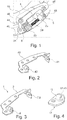
- a conventional receptacle 40 is shown, which is fastened with a first fastening element 34, a second fastening element 45 and a third fastening element 46 on a pressure plate 15.
- a spindle shaft 4 with a drive pinion 23 and a spindle drive 24 is held with a first end 5 in a socket 43.
- pawls 44 can be seen, which secure the position of the spindle nut 25 on the spindle drive 24 of the spindle shaft 4 in a set position via the drive pinion 23.
- Fig. 2 is the conventional recording 40 as in Fig. 1 shown, in which case the first opening 41 and the conventional second opening 42 can be seen. It is clear that in this case the spindle shaft 4 must be pushed through the conventional first opening 41, only then the drive pinion 23 and the spindle nut 25 on the spindle shaft 4, as in Fig. 1 shown, can be performed.
- Fig. 3 is a receptacle 3 a spindle holder 1 shown according to the invention, in which case the first opening 7 is set up as a precisely fitting position holder 9 for the spindle shaft 4, not shown.
- the second opening 8 is here a lateral opening, so that the spindle shaft 4, not shown here, after insertion of the first end 5 in the first opening 7 in the second opening 8 with the second end 6 can be pivoted (see. Fig. 7 ).
- a locking device 11 which has a connection surface 17 and a third opening 12, which is set up as a perfectly fitting second bearing holder 13.
- the receptacle 3 and the locking device 11 are in the FIGS. 3 and 4 designed as sheet metal parts, which are particularly inexpensive to manufacture and have a good weight-stability ratio.
- a spindle holder 1 is shown, from which a completely pre-assembled spindle shaft 4 is arranged separately.
- the spindle holder 1 has a receptacle 3, in which the first opening 7, which is formed as a precisely fitting first bearing holder 9, and a second opening 8 for pivoting, as shown in FIG Fig. 3 can be seen.
- a connecting surface 14 is provided, with which the spindle holder 1 can be attached to a component of the friction clutch, preferably a pressure plate 15 (see. Fig. 8 ).
- the spindle shaft 4 with the assembled drive pinion 23 and the spindle drive 24 is inserted with its first end 5 in the first opening 7 and with the second end 6 in the second opening 8 can be pivoted so that they as in Fig. 6 shown in the final assembly position 10 can be brought.
- Fig. 7 It is shown how the locking device 11 is applied by sliding the third opening 12 on the protruding second end 6 and so fixes the spindle shaft 4 in the final assembly position 10. Thereafter, the spindle holder including spindle shaft on a component of the friction clutch can be fastened, as for example in Fig. 8 is shown.
- a spindle holder 1 is shown, which also has a pawl 44, with which the spindle shaft 4 is secured in a setting position on the drive pinion 23, so that the spindle nut 25 has an adjusting ring 18 moved over it (not shown here, see for example Fig. 10 ) is secured.
- the first fastening element 34, the second fastening element 45 and the third fastening element 46 embodied here as a rivet
- both the spindle holder 1 together with the locking device 11 and the drive pawls 44 with the pressure plate 15 are fixed.
- the spindle shaft 4 is finally stored in its final assembly position 10.
- Fig. 9 is a pressure plate side detail view of the spindle holder 1 as in Fig. 8 shown, in which case the pressure plate 15 is removed for visibility, which is clearly seen that the second end 6 of the spindle shaft 4 is pivoted into the second opening 8 and the locking device 11 and the third opening 12, which as a perfectly fitting second bearing holder 13 is formed, is stored.
- the first fastening element 34 and the second fastening element 45 can be seen from below, where they are also designed as a rivet and not visible here rivet head the drive pawls 44 and the locking device 11 with the receptacle 3 (and the pressure plate 15, not shown) fix.
- the spindle nut 25 in a position in which the adjusting device 2 (see Fig. 10 ) is deflected to the maximum, so that the spindle nut 25 is moved to the drive pinion 23, wherein it should be noted that this is dependent on the commonly used thread direction of the spindle drive 24 (see. Fig. 8 ).
- a section of a friction clutch 16 is shown, in which an adjusting device 2 is shown in detail.
- the adjusting device 2 shown here is a path-controlled adjusting device, to which, however, the use of the spindle holder 1, as shown in the preceding figures, is not limited.
- the spindle nut 25 is moved in the direction of the drive pinion 23, so that the adjusting ring 18 is rotated.
- the first ramp 19 which rests on the second ramp 21 of the counter element 20, in which case the counter element 20 is integrally formed by the pressure plate 15, the total height 22 of the adjusting device 2 is changed.
- a changing distance 32 is compensated by the decrease in the total thickness 33 of the friction lining 31 of the friction disk 30.
- a travel for an actuator of the friction clutch 16 for the friction pack 29 despite decreasing total thickness 33 of the friction disc 30 with friction lining 31 (almost) constant.
- a motor vehicle 35 is shown with a drive unit 36, which is arranged with its motor axis 39 transversely to the longitudinal axis 38 in front of the driver's cab 37.
- the drive unit 36 is shown here as an internal combustion engine, which is connected via an output shaft 27 by means of a friction clutch 16 with a drive train 28 shown purely schematically here.
Landscapes
- Engineering & Computer Science (AREA)
- General Engineering & Computer Science (AREA)
- Mechanical Engineering (AREA)
- Mechanical Operated Clutches (AREA)
- Turning (AREA)
Claims (10)
- Support de broche (1) pour un dispositif ajusteur (2), comportant au moins les composants suivants :- une admission (3) pour un arbre de broche (4) doté d'une première extrémité (5) et d'une seconde extrémité (6), dans lequel l'admission (3) comporte une première ouverture (7) et une seconde ouverture (8), dans lequel la première ouverture (7) constitue un premier support (9) sur mesure à la première extrémité (5) de l'arbre de broche (4) ;- une surface de raccordement (14) sur laquelle le support de broche (1) peut être raccordé à un composant d'un accouplement à friction (16), de préférence avec une plaque de pression (15) ;caractérisé en ce que la seconde ouverture (8) est disposée de sorte que la seconde extrémité (6) de l'arbre de broche (4) peut être pivotée dans la seconde ouverture (8), afin d'être placée dans une position de montage final (10) ;- un dispositif de verrouillage (11), comportant une troisième ouverture (12) pour la seconde extrémité (6), dans lequel la troisième ouverture (12) constitue un second support (13) sur mesure pour la position de montage final (10) de l'arbre de broche (4), et dans lequel le dispositif de verrouillage (11) peut être fixé relativement à l'admission (3).
- Support de broche (1) selon la revendication 1, dans lequel la seconde ouverture (8) s'ouvre radialement à la surface de raccordement (14).
- Support de broche (1) selon la revendication 1 ou 2, dans lequel le dispositif de verrouillage (11) comporte une surface de fixation (17), laquelle est agencée à angle droit par rapport à la troisième ouverture (12) et avec laquelle le dispositif de verrouillage (11) peut être fixé à un composant d'un accouplement à friction (16), de préférence avec une plaque de pression (15).
- Support de broche (1) selon l'une des revendications précédentes, dans lequel l'admission (3), et de préférence le dispositif de verrouillage (11), sont formés de tôle, dans lequel les ouvertures (7, 8, 12) sont créées dans une section, laquelle est courbée à angle droit par rapport à la surface de raccordement (14) .
- Dispositif ajusteur (2) pour un accouplement à friction (16), comportant au moins les composants suivants :- une bague d'ajustage pouvant tourner (18) dotée d'au moins une première rampe (19) ;- un élément complémentaire (20) doté d'au moins une seconde rampe (21), dans lequel l'élément complémentaire (20) et la bague d'ajustage (18) constituent avec leurs rampes respectives (19, 21) arrangées l'une sur l'autre une hauteur totale (22), dans lequel la hauteur totale (22) est modifiable au moyen d'une rotation de la bague d'ajustage (18) au moyen de la première rampe (19) et de la seconde rampe (21) conjointement ;- un arbre de broche (4) doté d'un pignon moteur (23) et d'un actionneur à vis (24) doté d'un écrou de broche (25), dans lequel l'écrou de broche (25) est mobile en translation par entraînement de l'actionneur à vis (24) au moyen du pignon moteur (23), et dans lequel la bague d'ajustage (18) peut tourner au moyen d'un mouvement de translation de l'écrou de broche (25) et- un support de broche (1) selon l'une des revendications précédentes, disposé de façon à accueillir l'arbre de broche (4) et à être fixé à un composant d'un accouplement à friction (16), de préférence une plaque de pression (15).
- Accouplement à friction (16) doté d'un axe de rotation (26) pour raccorder de manière détachable un arbre entraîné (27) à un train d'entraînement (28), comportant au moins les composants suivants :- au moins un ensemble à friction (29) doté d'au moins une plaque de pression (15) et d'au moins un disque de friction correspondant (30), dans lequel une garniture de friction (31) abrasive est disposée entre la plaque de pression (15) et le disque de friction (30) correspondant, et dans lequel un moment de rotation peut être transmis sur l'ensemble à friction (29) à l'état comprimé au moyen de la garniture de friction (31) ; et- au moins un dispositif ajusteur (2) selon la revendication 5, disposé de façon à compenser une modification d'un écart (32) entre la plaque de pression (15) et le disque de friction correspondant (30) dû à une diminution d'épaisseur totale (33) d'une garniture de friction (31).
- Procédé de montage d'un arbre de broche (4) dans un support de broche (1) selon l'une des revendications 1 à 4, comportant au moins les étapes suivantes :a) introduction de l'arbre de broche (4) avec sa première extrémité (5) dans la première ouverture (7) de l'admission (3) ;b) introduction par pivot de l'arbre de broche (4) avec sa seconde extrémité (6) dans la seconde ouverture (8) de l'admission (3) ;c) enfilage du dispositif de verrouillage (11) avec la troisième ouverture (12) sur la seconde extrémité (6) de l'arbre de broche (4) ; etd) fixation du dispositif de verrouillage (11) relativement à l'admission (3), dans lequel l'arbre de broche (4) est fixé de manière radiale et axiale dans une position de montage final (10).
- Procédé selon la revendication 7, dans lequel un pignon moteur (23) pour l'arbre de broche (4) est monté sur l'arbre de broche (4) avant l'étape a).
- Procédé selon la revendication 7 ou 8, dans lequel l'admission (3) est fixée à un composant d'un accouplement à friction (16), de préférence à une plaque de pression (15), au moyen d'au moins un élément de fixation (34), en particulier au moyen d'au moins un rivet, et dans lequel le dispositif de verrouillage (11) est raccordé à l'admission (3) au moyen d'au moins un des éléments de fixation (34) de l'admission (3).
- Véhicule à moteur (35) comportant une unité motrice (36) dotée d'un arbre entraîné (27), d'un train d'entraînement (28) et d'un accouplement à friction (16) selon la revendication 6.
Applications Claiming Priority (2)
| Application Number | Priority Date | Filing Date | Title |
|---|---|---|---|
| DE102014205775 | 2014-03-27 | ||
| PCT/DE2015/200191 WO2015144167A2 (fr) | 2014-03-27 | 2015-03-24 | Support de broche pour dispositif de rattrapage |
Publications (2)
| Publication Number | Publication Date |
|---|---|
| EP3123052A2 EP3123052A2 (fr) | 2017-02-01 |
| EP3123052B1 true EP3123052B1 (fr) | 2018-11-14 |
Family
ID=53175213
Family Applications (1)
| Application Number | Title | Priority Date | Filing Date |
|---|---|---|---|
| EP15721544.3A Active EP3123052B1 (fr) | 2014-03-27 | 2015-03-24 | Support de broche pour dispositif de rattrapage |
Country Status (4)
| Country | Link |
|---|---|
| EP (1) | EP3123052B1 (fr) |
| CN (1) | CN106133364B (fr) |
| DE (1) | DE112015001475A5 (fr) |
| WO (1) | WO2015144167A2 (fr) |
Families Citing this family (2)
| Publication number | Priority date | Publication date | Assignee | Title |
|---|---|---|---|---|
| DE102016217824A1 (de) * | 2016-09-19 | 2018-03-22 | Schaeffler Technologies AG & Co. KG | Nachstelleinrichtung für eine Reibungskupplung |
| EP3543555A1 (fr) * | 2018-03-21 | 2019-09-25 | Heidelberger Druckmaschinen AG | Accouplement de compensation et barre d'impression dotée d'un tel accouplement de compensation |
Family Cites Families (3)
| Publication number | Priority date | Publication date | Assignee | Title |
|---|---|---|---|---|
| DE102010025330A1 (de) * | 2009-07-20 | 2011-01-27 | Luk Lamellen Und Kupplungsbau Beteiligungs Kg | Reibungskupplung mit Nachstelleinrichtung |
| DE102010035121B4 (de) * | 2009-09-24 | 2019-08-08 | Schaeffler Technologies AG & Co. KG | Nachstelleinrichtung für eine Reibungskupplung |
| DE102011015642B4 (de) * | 2011-03-31 | 2020-03-19 | Schaeffler Technologies AG & Co. KG | Nachstelleinrichtung für eine Reibungskupplung |
-
2015
- 2015-03-24 DE DE112015001475.6T patent/DE112015001475A5/de not_active Withdrawn
- 2015-03-24 EP EP15721544.3A patent/EP3123052B1/fr active Active
- 2015-03-24 CN CN201580016617.5A patent/CN106133364B/zh active Active
- 2015-03-24 WO PCT/DE2015/200191 patent/WO2015144167A2/fr active Application Filing
Non-Patent Citations (1)
| Title |
|---|
| None * |
Also Published As
| Publication number | Publication date |
|---|---|
| CN106133364B (zh) | 2018-07-03 |
| WO2015144167A3 (fr) | 2015-11-26 |
| CN106133364A (zh) | 2016-11-16 |
| DE112015001475A5 (de) | 2016-12-01 |
| EP3123052A2 (fr) | 2017-02-01 |
| WO2015144167A2 (fr) | 2015-10-01 |
Similar Documents
| Publication | Publication Date | Title |
|---|---|---|
| EP3677807B1 (fr) | Système de transmission pour un embrayage à friction à plusieurs disques | |
| EP3123050B1 (fr) | Dispositif de rattrapage de jeu à commande proportionnelle à la course | |
| DE102007051475A1 (de) | Verbindung eines Achsversatzausgleichselements und eines Innenrings eines Wälzlagers | |
| EP3123051B1 (fr) | Dispositif de rattrapage pour embrayage à friction | |
| DE102006022382A1 (de) | Vorrichtung und Verfahren zur Befestigung eines Wischermotors an ein Wischergestänge | |
| EP2908018B1 (fr) | Dispositif de fixation par encliquetage et logement d'encliquetage ainsi que procédé de montage | |
| EP3123052B1 (fr) | Support de broche pour dispositif de rattrapage | |
| DE102014208678A1 (de) | Bolzen für eine Reibkupplung | |
| DE102010045792B4 (de) | Kupplungsaggregat | |
| EP3123048B1 (fr) | Dispositif de rattrapage à commande proportionnelle à la course pour embrayage à friction | |
| EP3123053B1 (fr) | Dispositif de rattrapage pour embrayage à friction | |
| DE102014218242B4 (de) | Doppelkupplung mit einer Sicherungseinrichtung und Verfahren zu deren Montage | |
| DE102021108129B4 (de) | Drehmomentübertragungseinheit, Verfahren zur Herstellung der Drehmomentübertragungseinheit und Hybridgetriebe | |
| DE102013217116A1 (de) | Zentrierbolzen für eine Tellerfeder einer Reibkupplung | |
| WO2015003701A2 (fr) | Élément d'équilibrage pour équilibrer un embrayage à friction | |
| WO2013167365A1 (fr) | Ressort de disque d'embrayage à friction | |
| DE102015219456B3 (de) | Verfahren zur Einstellung eines Betriebspunktes einer Reibungskupplung | |
| DE102015206026A1 (de) | Kupplungsdeckel mit einer Rotationsachse und Tellerfeder für eine Reibkupplung, sowie ein Montageverfahren und eine Verwendung von Hülsen zum Montieren und zum Zentrieren einer Tellerfeder in dem Kupplungsdeckel | |
| EP2684725B1 (fr) | Système de logement pour un système d'entraînement | |
| DE102021101499A1 (de) | Drehschwingungsdämpfer | |
| DE102013220624A1 (de) | Tellerfeder für eine Reibkupplung | |
| DE102017118142A1 (de) | Reibscheibe für eine Reibkupplung | |
| DE102013207054A1 (de) | Reibkupplung | |
| DE102015206850A1 (de) | Kupplungsdeckel mit einer Rotationsachse für eine Reibkupplung | |
| WO2014180476A2 (fr) | Procédé de production d'un composant de transmission de couple, en particulier pour un véhicule à moteur, ainsi que ledit composant et ledit véhicule à moteur |
Legal Events
| Date | Code | Title | Description |
|---|---|---|---|
| STAA | Information on the status of an ep patent application or granted ep patent |
Free format text: STATUS: THE INTERNATIONAL PUBLICATION HAS BEEN MADE |
|
| PUAI | Public reference made under article 153(3) epc to a published international application that has entered the european phase |
Free format text: ORIGINAL CODE: 0009012 |
|
| STAA | Information on the status of an ep patent application or granted ep patent |
Free format text: STATUS: REQUEST FOR EXAMINATION WAS MADE |
|
| 17P | Request for examination filed |
Effective date: 20161027 |
|
| AK | Designated contracting states |
Kind code of ref document: A2 Designated state(s): AL AT BE BG CH CY CZ DE DK EE ES FI FR GB GR HR HU IE IS IT LI LT LU LV MC MK MT NL NO PL PT RO RS SE SI SK SM TR |
|
| AX | Request for extension of the european patent |
Extension state: BA ME |
|
| DAV | Request for validation of the european patent (deleted) | ||
| DAX | Request for extension of the european patent (deleted) | ||
| GRAP | Despatch of communication of intention to grant a patent |
Free format text: ORIGINAL CODE: EPIDOSNIGR1 |
|
| STAA | Information on the status of an ep patent application or granted ep patent |
Free format text: STATUS: GRANT OF PATENT IS INTENDED |
|
| INTG | Intention to grant announced |
Effective date: 20171113 |
|
| GRAS | Grant fee paid |
Free format text: ORIGINAL CODE: EPIDOSNIGR3 |
|
| GRAA | (expected) grant |
Free format text: ORIGINAL CODE: 0009210 |
|
| STAA | Information on the status of an ep patent application or granted ep patent |
Free format text: STATUS: THE PATENT HAS BEEN GRANTED |
|
| AK | Designated contracting states |
Kind code of ref document: B1 Designated state(s): AL AT BE BG CH CY CZ DE DK EE ES FI FR GB GR HR HU IE IS IT LI LT LU LV MC MK MT NL NO PL PT RO RS SE SI SK SM TR |
|
| REG | Reference to a national code |
Ref country code: CH Ref legal event code: EP Ref country code: AT Ref legal event code: REF Ref document number: 1065192 Country of ref document: AT Kind code of ref document: T Effective date: 20181115 |
|
| REG | Reference to a national code |
Ref country code: DE Ref legal event code: R096 Ref document number: 502015006870 Country of ref document: DE |
|
| REG | Reference to a national code |
Ref country code: IE Ref legal event code: FG4D Free format text: LANGUAGE OF EP DOCUMENT: GERMAN |
|
| REG | Reference to a national code |
Ref country code: NL Ref legal event code: MP Effective date: 20181114 |
|
| REG | Reference to a national code |
Ref country code: LT Ref legal event code: MG4D |
|
| PG25 | Lapsed in a contracting state [announced via postgrant information from national office to epo] |
Ref country code: ES Free format text: LAPSE BECAUSE OF FAILURE TO SUBMIT A TRANSLATION OF THE DESCRIPTION OR TO PAY THE FEE WITHIN THE PRESCRIBED TIME-LIMIT Effective date: 20181114 Ref country code: IS Free format text: LAPSE BECAUSE OF FAILURE TO SUBMIT A TRANSLATION OF THE DESCRIPTION OR TO PAY THE FEE WITHIN THE PRESCRIBED TIME-LIMIT Effective date: 20190314 Ref country code: LT Free format text: LAPSE BECAUSE OF FAILURE TO SUBMIT A TRANSLATION OF THE DESCRIPTION OR TO PAY THE FEE WITHIN THE PRESCRIBED TIME-LIMIT Effective date: 20181114 Ref country code: NO Free format text: LAPSE BECAUSE OF FAILURE TO SUBMIT A TRANSLATION OF THE DESCRIPTION OR TO PAY THE FEE WITHIN THE PRESCRIBED TIME-LIMIT Effective date: 20190214 Ref country code: HR Free format text: LAPSE BECAUSE OF FAILURE TO SUBMIT A TRANSLATION OF THE DESCRIPTION OR TO PAY THE FEE WITHIN THE PRESCRIBED TIME-LIMIT Effective date: 20181114 Ref country code: BG Free format text: LAPSE BECAUSE OF FAILURE TO SUBMIT A TRANSLATION OF THE DESCRIPTION OR TO PAY THE FEE WITHIN THE PRESCRIBED TIME-LIMIT Effective date: 20190214 Ref country code: FI Free format text: LAPSE BECAUSE OF FAILURE TO SUBMIT A TRANSLATION OF THE DESCRIPTION OR TO PAY THE FEE WITHIN THE PRESCRIBED TIME-LIMIT Effective date: 20181114 Ref country code: LV Free format text: LAPSE BECAUSE OF FAILURE TO SUBMIT A TRANSLATION OF THE DESCRIPTION OR TO PAY THE FEE WITHIN THE PRESCRIBED TIME-LIMIT Effective date: 20181114 |
|
| PG25 | Lapsed in a contracting state [announced via postgrant information from national office to epo] |
Ref country code: SE Free format text: LAPSE BECAUSE OF FAILURE TO SUBMIT A TRANSLATION OF THE DESCRIPTION OR TO PAY THE FEE WITHIN THE PRESCRIBED TIME-LIMIT Effective date: 20181114 Ref country code: NL Free format text: LAPSE BECAUSE OF FAILURE TO SUBMIT A TRANSLATION OF THE DESCRIPTION OR TO PAY THE FEE WITHIN THE PRESCRIBED TIME-LIMIT Effective date: 20181114 Ref country code: AL Free format text: LAPSE BECAUSE OF FAILURE TO SUBMIT A TRANSLATION OF THE DESCRIPTION OR TO PAY THE FEE WITHIN THE PRESCRIBED TIME-LIMIT Effective date: 20181114 Ref country code: RS Free format text: LAPSE BECAUSE OF FAILURE TO SUBMIT A TRANSLATION OF THE DESCRIPTION OR TO PAY THE FEE WITHIN THE PRESCRIBED TIME-LIMIT Effective date: 20181114 Ref country code: PT Free format text: LAPSE BECAUSE OF FAILURE TO SUBMIT A TRANSLATION OF THE DESCRIPTION OR TO PAY THE FEE WITHIN THE PRESCRIBED TIME-LIMIT Effective date: 20190314 Ref country code: GR Free format text: LAPSE BECAUSE OF FAILURE TO SUBMIT A TRANSLATION OF THE DESCRIPTION OR TO PAY THE FEE WITHIN THE PRESCRIBED TIME-LIMIT Effective date: 20190215 |
|
| PG25 | Lapsed in a contracting state [announced via postgrant information from national office to epo] |
Ref country code: CZ Free format text: LAPSE BECAUSE OF FAILURE TO SUBMIT A TRANSLATION OF THE DESCRIPTION OR TO PAY THE FEE WITHIN THE PRESCRIBED TIME-LIMIT Effective date: 20181114 Ref country code: PL Free format text: LAPSE BECAUSE OF FAILURE TO SUBMIT A TRANSLATION OF THE DESCRIPTION OR TO PAY THE FEE WITHIN THE PRESCRIBED TIME-LIMIT Effective date: 20181114 Ref country code: DK Free format text: LAPSE BECAUSE OF FAILURE TO SUBMIT A TRANSLATION OF THE DESCRIPTION OR TO PAY THE FEE WITHIN THE PRESCRIBED TIME-LIMIT Effective date: 20181114 Ref country code: IT Free format text: LAPSE BECAUSE OF FAILURE TO SUBMIT A TRANSLATION OF THE DESCRIPTION OR TO PAY THE FEE WITHIN THE PRESCRIBED TIME-LIMIT Effective date: 20181114 |
|
| REG | Reference to a national code |
Ref country code: DE Ref legal event code: R097 Ref document number: 502015006870 Country of ref document: DE |
|
| PG25 | Lapsed in a contracting state [announced via postgrant information from national office to epo] |
Ref country code: EE Free format text: LAPSE BECAUSE OF FAILURE TO SUBMIT A TRANSLATION OF THE DESCRIPTION OR TO PAY THE FEE WITHIN THE PRESCRIBED TIME-LIMIT Effective date: 20181114 Ref country code: SM Free format text: LAPSE BECAUSE OF FAILURE TO SUBMIT A TRANSLATION OF THE DESCRIPTION OR TO PAY THE FEE WITHIN THE PRESCRIBED TIME-LIMIT Effective date: 20181114 Ref country code: RO Free format text: LAPSE BECAUSE OF FAILURE TO SUBMIT A TRANSLATION OF THE DESCRIPTION OR TO PAY THE FEE WITHIN THE PRESCRIBED TIME-LIMIT Effective date: 20181114 Ref country code: SK Free format text: LAPSE BECAUSE OF FAILURE TO SUBMIT A TRANSLATION OF THE DESCRIPTION OR TO PAY THE FEE WITHIN THE PRESCRIBED TIME-LIMIT Effective date: 20181114 |
|
| PLBE | No opposition filed within time limit |
Free format text: ORIGINAL CODE: 0009261 |
|
| STAA | Information on the status of an ep patent application or granted ep patent |
Free format text: STATUS: NO OPPOSITION FILED WITHIN TIME LIMIT |
|
| 26N | No opposition filed |
Effective date: 20190815 |
|
| PG25 | Lapsed in a contracting state [announced via postgrant information from national office to epo] |
Ref country code: MC Free format text: LAPSE BECAUSE OF FAILURE TO SUBMIT A TRANSLATION OF THE DESCRIPTION OR TO PAY THE FEE WITHIN THE PRESCRIBED TIME-LIMIT Effective date: 20181114 Ref country code: SI Free format text: LAPSE BECAUSE OF FAILURE TO SUBMIT A TRANSLATION OF THE DESCRIPTION OR TO PAY THE FEE WITHIN THE PRESCRIBED TIME-LIMIT Effective date: 20181114 |
|
| REG | Reference to a national code |
Ref country code: CH Ref legal event code: PL |
|
| GBPC | Gb: european patent ceased through non-payment of renewal fee |
Effective date: 20190324 |
|
| PG25 | Lapsed in a contracting state [announced via postgrant information from national office to epo] |
Ref country code: LU Free format text: LAPSE BECAUSE OF NON-PAYMENT OF DUE FEES Effective date: 20190324 |
|
| REG | Reference to a national code |
Ref country code: BE Ref legal event code: MM Effective date: 20190331 |
|
| PG25 | Lapsed in a contracting state [announced via postgrant information from national office to epo] |
Ref country code: CH Free format text: LAPSE BECAUSE OF NON-PAYMENT OF DUE FEES Effective date: 20190331 Ref country code: GB Free format text: LAPSE BECAUSE OF NON-PAYMENT OF DUE FEES Effective date: 20190324 Ref country code: LI Free format text: LAPSE BECAUSE OF NON-PAYMENT OF DUE FEES Effective date: 20190331 Ref country code: IE Free format text: LAPSE BECAUSE OF NON-PAYMENT OF DUE FEES Effective date: 20190324 |
|
| PG25 | Lapsed in a contracting state [announced via postgrant information from national office to epo] |
Ref country code: BE Free format text: LAPSE BECAUSE OF NON-PAYMENT OF DUE FEES Effective date: 20190331 |
|
| PG25 | Lapsed in a contracting state [announced via postgrant information from national office to epo] |
Ref country code: TR Free format text: LAPSE BECAUSE OF FAILURE TO SUBMIT A TRANSLATION OF THE DESCRIPTION OR TO PAY THE FEE WITHIN THE PRESCRIBED TIME-LIMIT Effective date: 20181114 |
|
| PG25 | Lapsed in a contracting state [announced via postgrant information from national office to epo] |
Ref country code: MT Free format text: LAPSE BECAUSE OF FAILURE TO SUBMIT A TRANSLATION OF THE DESCRIPTION OR TO PAY THE FEE WITHIN THE PRESCRIBED TIME-LIMIT Effective date: 20181114 |
|
| REG | Reference to a national code |
Ref country code: AT Ref legal event code: MM01 Ref document number: 1065192 Country of ref document: AT Kind code of ref document: T Effective date: 20200324 |
|
| PG25 | Lapsed in a contracting state [announced via postgrant information from national office to epo] |
Ref country code: CY Free format text: LAPSE BECAUSE OF FAILURE TO SUBMIT A TRANSLATION OF THE DESCRIPTION OR TO PAY THE FEE WITHIN THE PRESCRIBED TIME-LIMIT Effective date: 20181114 |
|
| PG25 | Lapsed in a contracting state [announced via postgrant information from national office to epo] |
Ref country code: HU Free format text: LAPSE BECAUSE OF FAILURE TO SUBMIT A TRANSLATION OF THE DESCRIPTION OR TO PAY THE FEE WITHIN THE PRESCRIBED TIME-LIMIT; INVALID AB INITIO Effective date: 20150324 |
|
| PG25 | Lapsed in a contracting state [announced via postgrant information from national office to epo] |
Ref country code: AT Free format text: LAPSE BECAUSE OF NON-PAYMENT OF DUE FEES Effective date: 20200324 |
|
| PG25 | Lapsed in a contracting state [announced via postgrant information from national office to epo] |
Ref country code: MK Free format text: LAPSE BECAUSE OF FAILURE TO SUBMIT A TRANSLATION OF THE DESCRIPTION OR TO PAY THE FEE WITHIN THE PRESCRIBED TIME-LIMIT Effective date: 20181114 |
|
| PGFP | Annual fee paid to national office [announced via postgrant information from national office to epo] |
Ref country code: FR Payment date: 20230324 Year of fee payment: 9 |
|
| P01 | Opt-out of the competence of the unified patent court (upc) registered |
Effective date: 20230523 |
|
| PGFP | Annual fee paid to national office [announced via postgrant information from national office to epo] |
Ref country code: DE Payment date: 20230519 Year of fee payment: 9 |