EP3122947B1 - Outil de retrait/d'installation de broche de retenue et procédé associé - Google Patents
Outil de retrait/d'installation de broche de retenue et procédé associé Download PDFInfo
- Publication number
- EP3122947B1 EP3122947B1 EP15767813.7A EP15767813A EP3122947B1 EP 3122947 B1 EP3122947 B1 EP 3122947B1 EP 15767813 A EP15767813 A EP 15767813A EP 3122947 B1 EP3122947 B1 EP 3122947B1
- Authority
- EP
- European Patent Office
- Prior art keywords
- tool
- components
- heads
- retaining pin
- actuator
- Prior art date
- Legal status (The legal status is an assumption and is not a legal conclusion. Google has not performed a legal analysis and makes no representation as to the accuracy of the status listed.)
- Active
Links
- 238000000034 method Methods 0.000 title claims description 10
- 238000009434 installation Methods 0.000 title claims description 5
- 230000007246 mechanism Effects 0.000 claims description 8
- 238000005065 mining Methods 0.000 claims description 7
- 238000012986 modification Methods 0.000 description 2
- 230000004048 modification Effects 0.000 description 2
- 208000027418 Wounds and injury Diseases 0.000 description 1
- 230000006378 damage Effects 0.000 description 1
- 208000014674 injury Diseases 0.000 description 1
- 238000003466 welding Methods 0.000 description 1
Images


Classifications
-
- E—FIXED CONSTRUCTIONS
- E02—HYDRAULIC ENGINEERING; FOUNDATIONS; SOIL SHIFTING
- E02F—DREDGING; SOIL-SHIFTING
- E02F9/00—Component parts of dredgers or soil-shifting machines, not restricted to one of the kinds covered by groups E02F3/00 - E02F7/00
- E02F9/28—Small metalwork for digging elements, e.g. teeth scraper bits
- E02F9/2891—Tools for assembling or disassembling
-
- B—PERFORMING OPERATIONS; TRANSPORTING
- B25—HAND TOOLS; PORTABLE POWER-DRIVEN TOOLS; MANIPULATORS
- B25B—TOOLS OR BENCH DEVICES NOT OTHERWISE PROVIDED FOR, FOR FASTENING, CONNECTING, DISENGAGING OR HOLDING
- B25B27/00—Hand tools, specially adapted for fitting together or separating parts or objects whether or not involving some deformation, not otherwise provided for
- B25B27/02—Hand tools, specially adapted for fitting together or separating parts or objects whether or not involving some deformation, not otherwise provided for for connecting objects by press fit or detaching same
- B25B27/04—Hand tools, specially adapted for fitting together or separating parts or objects whether or not involving some deformation, not otherwise provided for for connecting objects by press fit or detaching same inserting or withdrawing keys
-
- E—FIXED CONSTRUCTIONS
- E02—HYDRAULIC ENGINEERING; FOUNDATIONS; SOIL SHIFTING
- E02F—DREDGING; SOIL-SHIFTING
- E02F9/00—Component parts of dredgers or soil-shifting machines, not restricted to one of the kinds covered by groups E02F3/00 - E02F7/00
- E02F9/28—Small metalwork for digging elements, e.g. teeth scraper bits
- E02F9/2883—Wear elements for buckets or implements in general
Definitions
- the present invention relates to a tool for installation and/or removal of a retaining pin to or from aligned bores in components.
- the present invention relates to a tool for use to install or remove a retaining pin, which is typically used for attachment of a wear tooth to a tooth adaptor of a mining, earthmoving or like vehicle or machine.
- the present invention also relates to a method of installing or removing such a retaining pin.
- Wear teeth are typically attached to mining or earthmoving equipment such that they can be readily removed and replaced as they wear out. It is well known to attach a wear tooth to a tooth adaptor by means of a retaining pin being positioned in aligned bores of the wear tooth and tooth adaptor.
- such a retaining pin Whilst the use of such a retaining pin has significant time and cost advantages over previous methods of attaching a wear tooth to a tooth adaptor by welding or other forms of securement, such a retaining pin is typically removed using an extractor pin which is then forcibly struck with a sledge hammer or the like. This operation requires considerable physical effort and is also prone to user injury.
- US 5 210 919 A discloses a tool assembly for installing and removing horizontally oriented retaining pins in a mechanical joint between a bucket tooth and a tooth adapter, which tool assembly includes first and second lever members and first and second threaded members which are threadably connected to the respective first and second lever members.
- the second lever member is pivotably connected to the first member.
- the tool assembly is adapted to be placed over a bucket tooth having a horizontally oriented retaining pin, with the second threaded member aligning with and contacting the retaining pin.
- a portion of the first lever member contacts the tooth and the second threaded member contacts the pin and forces the pin into the joint, or out of the joint.
- the present invention seeks to overcome at least some of the disadvantages of the prior art, by providing a tool for installation or removal of a retaining pin which requires less physical effort or exertion by a user, and is typically safer, in use.
- the present invention provides a tool for installation or removal of a retaining pin according to claim 1.
- the actuator includes at least one of a hydraulic cylinder; a pneumatic cylinder; and, an electric motor.
- the tool further includes a pair of adjustable arms extending outwardly from each of said heads, for positional adjustment of said brace members relative to each other.
- said drive rod and said actuator are substantially housed in a first of said heads.
- the tool further includes a pin receptacle is housed within a second of said heads.
- said first and second components include a wear tooth and tooth adaptor of a mining, earthmoving or like vehicle or machine.
- the present invention also seeks to provide a tool and a method for installing or removing a retaining pin to or from aligned bores in first and second components in which the process is effectively performed without substantive physical effort of a user, but rather, by utilising an actuator such as, but not limited to, a hydraulic cylinder, a pneumatic cylinder or an electric motor.
- an actuator such as, but not limited to, a hydraulic cylinder, a pneumatic cylinder or an electric motor.
- the present invention provides a method of installing or removing a retaining pin according to claim 8.
- said actuator includes at least one of:
- said first and second components include a wear tooth and tooth adaptor of a mining, earthmoving or like vehicle or machine.
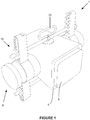
- the tool is typically used for installing or removing a retaining pin 2 (as shown in Figures 2 , 4 and 5 ) to or from aligned bores 3 and 4 provided in a wear tooth 5 and tooth adaptor 6, respectively.
- the tool 1 includes a drive rod 7, which is adapted to be positioned adjacent a first end 8 of the aligned bores 3 and 4, and, an actuator 9, operable to move the drive rod 7, to thereby push the retaining pin 2 into or from the aligned bores 3 and 4.
- the tool 1 further includes a securement mechanism, embodied in the form of a frame 10, which is adapted to releasably secure or attach the tool 1 to at least one of the first and second components 5 and 6.
- the securement mechanism or frame 10 will be described in further detail hereinafter.
- the tool 1 has advantages over the prior art in that it includes an automated actuator 9.
- the actuator preferably includes any one or more of a hydraulic cylinder, a pneumatic cylinder, an electric motor, or some other similar electromechanical or other actuator.
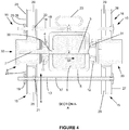
- the securement mechanism 10 includes a frame, which is adapted to substantially surround the first and second components 5 and 6.
- the frame includes a pair of heads 11 and 12 each adapted to be substantially aligned with the bores 3 and 4 of the components 5 and 6.
- the frame further includes a pair of adjustable brace members 13 and 14 which include adjustment mechanisms 15 and 16 for positional adjustment of the heads 11 and 12 relative to each other.
- the adjustment mechanisms 15 and 16 may be embodied in the form of threaded rods 17 and 18 and cooperating nuts 19, 20, 21 and 22 which may be adjusted along rods 17 and 18 and then tightened to thereby effectively secure the heads 11 and 12 relative to each other.
- One of the threaded rods may incorporate a handle 23, for user convenience in carrying and/or positioning the tool.
- the tool 1 may further include a pair of adjustable arms 25 and 26 extending outwardly from the first of the head 11, and a further pair of adjustable arms 27 and 28 extending from the second head 12.
- These adjustable arms allow for positional adjustment of the brace members 13 and 14 relative to each other and, as shown, may be embodied in the form of a slide channel which is adapted to cooperatively engage the nuts 21 and 22.
- Other forms of adjustment mechanisms to permit adjustment of the brace members 13 and 14, and, the adjustable arms 25, 26, 27 and 28 will become apparent and should be considered to be incorporated within the scope of the invention.
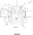
- Each head 11 and 12 may further include a pivoting neck portion 30 and 31, for angular adjustment of the heads 11 and 12 such that the tool 1 may be securely engaged with at least one of the components 5, particularly when the contact surfaces of the component 5 are not perpendicular to the heads 11 and 12, but rather, are provided at a transverse angular disposition relative thereto.
- a pivoting neck portion 30 and 31 for angular adjustment of the heads 11 and 12 such that the tool 1 may be securely engaged with at least one of the components 5, particularly when the contact surfaces of the component 5 are not perpendicular to the heads 11 and 12, but rather, are provided at a transverse angular disposition relative thereto.
- Various alternative forms of pivotal mechanisms will become apparent and should also be considered to be within the scope of the invention.
- the drive rod 7 and actuator 9 are provided in a housing 32 in a first of the heads 11, and a pin receptacle 33 is housed within a second of the heads 12.
- the device of the present invention is particularly useful for installing and/or removing a retaining pin either onto or from a wear tooth and tooth adaptor of mining, earthmoving or like vehicle or machine.
- the device may typically be operated such that the actuator 9 moves the drive rod 7 to thereby push the retaining pin 2 into or from the aligned bores.
- the device may of course be utilised to just perform one of these operations of either installing or removing the retaining pin, or both.
- the tool is preferably initially secured to one of the components.
- the tool 1 is installed and secured to the wear tooth 5 by firstly positioning the tool about the wear tooth, adjusting the adjustable brace members 13 and 14 as necessary, and adjusting the adjustable arms 25, 26, 27 and 28 as necessary, and then securing the various nuts and rods, such that the tool is preferably tightly abutted against the wear tooth with the pivoting neck portions angled appropriately from the heads such that the tool is firmly secured.
- the actuator 9 is operated and either draws the retaining pin into the aligned bores from the pin receptacle 33, or, if the pin 2 is required to be removed, the actuator is operated such that the drive rod is moved in the direction shown by arrow 34 such that the drive rod 7 abuts against the end of the retaining pin 2 to push the pin from the "installed” position shown in the drawings, to the "removed” position wherein the pin is pushed into the pin receptacle 33.
Claims (10)
- Outil (1) d'installation ou de retrait d'une tige de retenue (2) dans/à partir de trous (3, 4) dans des premier et second composants, ledit outil (1) comprenant:un mécanisme de fixation adapté pour fixer amovible ledit outil (1) audit premier et/ou audit second composant, comprenant un cadre (10) adapté pour entourer sensiblement ledit premier et ledit second composant, ledit cadre comprenant une paire de têtes (11, 12) et une paire d'éléments de jambe de force (15, 16), pour le positionnement desdites têtes (11, 12) l'une par rapport à l'autre, et chaque tête comprenant une partie de col pivotante (30, 31) pour son réglage angulaire, et étant adaptée pour aligner sensiblement lesdits trous desdits composants;une tige de commande (7) adaptée pour être adjacente à une première extrémité desdits trous alignés; et,un actionneur (9), permettant de déplacer ladite tige de commande (7), pour ainsi pousser ladite tige de retenue (2) dans ou en dehors desdits trous alignés.
- Outil (1) selon la revendication 1, les têtes (11, 12) étant adaptées pour venir en butée avec au moins ledit premier et/ou ledit second composant.
- Outil (1) la revendication 1 ou la revendication 2, ledit actionneur (9) comprenant au moins:un vérin hydraulique et/ouun vérin pneumatique et/ouun moteur électrique.
- Outil (1) selon la revendication 1, comprenant en outre une paire de bras réglables (25, 26, 27, 28) partant vers l'extérieur à partir de chacune desdites têtes (11, 12) pour positionner lesdits éléments de jambe de force (15, 16) l'un par rapport à l'autre.
- Outil (1) selon l'une quelconque des revendications 1 à 4, ladite tige de commande (7) et ledit actionneur (9) étant logés sensiblement dans la première tête parmi lesdites têtes (11).
- Outil (1) selon l'une quelconque des revendications 1 à 5, comprenant un logement (33) de tige logé à l'intérieur de la seconde tête parmi lesdites têtes (12).
- Outil (1) selon l'une quelconque des revendications 1 à 6, ledit premier et ledit second composant comprenant une dent d'usure et un adaptateur de dent d'une haveuse ou matériel de terrassement ou similaire.
- Procédé d'installation ou de retrait d'une tige de retenue (2) dans ou à partir de trous alignés de premier et second composant à l'aide d'un outil (1) selon l'une quelconque des revendications 1 à 7, comprenant les étapes consistant à:fixer ledit outil (1) dans au moins l'un desdits composants; etfaire fonctionner ledit outil (1) de telle sorte que l'actionneur (9) déplace une tige de commande (7) pour ainsi pousser ladite tige de retenue (2) dans ou en dehors desdits trous alignés.
- Procédé selon la revendication 8, ledit actionneur (9) comprenant au moins:un vérin hydraulique et/ouun vérin pneumatique; et/ouun moteur électrique.
- Procédé selon l'une quelconque des revendications 8 ou 9, ledit premier et ledit second composant comprenant une dent d'usure et un adaptateur de dent d'une haveuse, d'un équipement de terrassement ou similaire.
Applications Claiming Priority (2)
| Application Number | Priority Date | Filing Date | Title |
|---|---|---|---|
| AU2014901060A AU2014901060A0 (en) | 2014-03-25 | Retaining pin installation/removal tool and method | |
| PCT/AU2015/050080 WO2015143498A1 (fr) | 2014-03-25 | 2015-02-27 | Outil de retrait/d'installation de broche de retenue et procédé associé |
Publications (3)
| Publication Number | Publication Date |
|---|---|
| EP3122947A1 EP3122947A1 (fr) | 2017-02-01 |
| EP3122947A4 EP3122947A4 (fr) | 2017-11-29 |
| EP3122947B1 true EP3122947B1 (fr) | 2020-02-05 |
Family
ID=54193779
Family Applications (1)
| Application Number | Title | Priority Date | Filing Date |
|---|---|---|---|
| EP15767813.7A Active EP3122947B1 (fr) | 2014-03-25 | 2015-02-27 | Outil de retrait/d'installation de broche de retenue et procédé associé |
Country Status (7)
| Country | Link |
|---|---|
| US (1) | US10100499B2 (fr) |
| EP (1) | EP3122947B1 (fr) |
| AU (1) | AU2015234705B2 (fr) |
| BR (1) | BR112016022256B1 (fr) |
| CA (1) | CA2942415C (fr) |
| CL (1) | CL2016002385A1 (fr) |
| WO (1) | WO2015143498A1 (fr) |
Families Citing this family (3)
| Publication number | Priority date | Publication date | Assignee | Title |
|---|---|---|---|---|
| CN108907672B (zh) * | 2018-09-17 | 2024-01-05 | 江苏大亚铝业有限公司 | 一种液压缸销轴安装工具及其使用方法 |
| US11274423B2 (en) * | 2019-02-22 | 2022-03-15 | G. Dennis Gordon | Road grader blade teeth removal apparatus |
| AU2020351828A1 (en) | 2019-09-23 | 2022-03-24 | Cqms Pty Ltd | A device for removing a wear member |
Family Cites Families (5)
| Publication number | Priority date | Publication date | Assignee | Title |
|---|---|---|---|---|
| US3967361A (en) * | 1975-06-09 | 1976-07-06 | Caterpillar Tractor Co. | Pin remover and installer |
| US5210919A (en) * | 1992-04-27 | 1993-05-18 | Caterpillar Inc. | Tool assembly |
| US6453657B1 (en) | 2000-02-29 | 2002-09-24 | Sony Corporation | Hydraulic device for assembly and disassembly of conveyor chains using interference-fit connecting pins and method of using the same |
| US7891084B1 (en) * | 2004-11-29 | 2011-02-22 | The Sollami Company | Extraction device for removing a quick-change tool holder from a base block mounting |
| FR2934191B1 (fr) * | 2008-07-22 | 2010-09-03 | Jean Sevrette | Perfectionnement a un dispositif pour l'insertion et l'extraction d'axes d'articulation de maillons de chaines |
-
2015
- 2015-02-27 BR BR112016022256-3A patent/BR112016022256B1/pt active IP Right Grant
- 2015-02-27 EP EP15767813.7A patent/EP3122947B1/fr active Active
- 2015-02-27 WO PCT/AU2015/050080 patent/WO2015143498A1/fr active Application Filing
- 2015-02-27 AU AU2015234705A patent/AU2015234705B2/en active Active
- 2015-02-27 CA CA2942415A patent/CA2942415C/fr active Active
- 2015-02-27 US US15/126,241 patent/US10100499B2/en active Active
-
2016
- 2016-09-22 CL CL2016002385A patent/CL2016002385A1/es unknown
Non-Patent Citations (1)
| Title |
|---|
| None * |
Also Published As
| Publication number | Publication date |
|---|---|
| CA2942415A1 (fr) | 2015-10-01 |
| EP3122947A1 (fr) | 2017-02-01 |
| WO2015143498A1 (fr) | 2015-10-01 |
| CA2942415C (fr) | 2021-05-25 |
| BR112016022256A2 (fr) | 2017-08-15 |
| AU2015234705B2 (en) | 2018-11-15 |
| EP3122947A4 (fr) | 2017-11-29 |
| AU2015234705A1 (en) | 2016-09-29 |
| US10100499B2 (en) | 2018-10-16 |
| BR112016022256B1 (pt) | 2022-01-18 |
| CL2016002385A1 (es) | 2017-02-03 |
| US20170081829A1 (en) | 2017-03-23 |
Similar Documents
| Publication | Publication Date | Title |
|---|---|---|
| US7204021B2 (en) | Multi-purpose plastic pipe cutter | |
| EP3122947B1 (fr) | Outil de retrait/d'installation de broche de retenue et procédé associé | |
| US20120222335A1 (en) | Disassembly of inter-fitting components | |
| US20120073101A1 (en) | Pulling pliers method and apparatus | |
| WO2003049882A1 (fr) | Marteau a inertie | |
| US9328571B2 (en) | Well head wrench | |
| KR20160078488A (ko) | 터널 천공기용 절단 공구 홀더 및 관련된 절단 조립체 | |
| US8528239B2 (en) | Quick coupling device for connecting a tool to a handling equipment, such as the arm of an excavator | |
| US10646906B2 (en) | Mechanism for retention of multiple apparatus on plumbing tools | |
| EP2949488B1 (fr) | Unité d'outil de montage/démontage d'outil préchargé | |
| EP2128512A2 (fr) | Outil d'installation de collier de serrage | |
| WO2018066010A1 (fr) | Dispositif d'extraction et d'introduction de douilles | |
| US20210039237A1 (en) | An expandable device, apparatus and assembly for pushing apart opposed surfaces | |
| JP6975790B2 (ja) | レバー組立品 | |
| US11913176B2 (en) | Handheld tool for installing or removing railway track fasteners | |
| US8234764B1 (en) | Multi-purpose prying tool | |
| DE10260324A1 (de) | Elektrisches Werkzeug | |
| JP2007530293A (ja) | クランプ用プライヤ | |
| JP3139748U (ja) | 床材剥離装置 | |
| AU2022203338B2 (en) | Article Handler | |
| JP5730723B2 (ja) | Pcカットアウト用仮送電具 | |
| US20180230679A1 (en) | Bolt head holding tool and methods of fastening bucket lip protectors | |
| CA3122009A1 (fr) | Appareils, systemes et methodes pour retirer et installer une dent de tronconnage dans une lame de scie | |
| KR20180079127A (ko) | 정수기용 만능툴 시스템 | |
| CA2894017A1 (fr) | Outil d'extraction de crampons ayant differents points d'appui destine a des pneus presentant une usure differente de bande de roulement |
Legal Events
| Date | Code | Title | Description |
|---|---|---|---|
| PUAI | Public reference made under article 153(3) epc to a published international application that has entered the european phase |
Free format text: ORIGINAL CODE: 0009012 |
|
| STAA | Information on the status of an ep patent application or granted ep patent |
Free format text: STATUS: REQUEST FOR EXAMINATION WAS MADE |
|
| 17P | Request for examination filed |
Effective date: 20160912 |
|
| AK | Designated contracting states |
Kind code of ref document: A1 Designated state(s): AL AT BE BG CH CY CZ DE DK EE ES FI FR GB GR HR HU IE IS IT LI LT LU LV MC MK MT NL NO PL PT RO RS SE SI SK SM TR |
|
| AX | Request for extension of the european patent |
Extension state: BA ME |
|
| DAX | Request for extension of the european patent (deleted) | ||
| A4 | Supplementary search report drawn up and despatched |
Effective date: 20171103 |
|
| RIC1 | Information provided on ipc code assigned before grant |
Ipc: E02F 9/28 20060101AFI20171026BHEP Ipc: B23P 19/04 20060101ALI20171026BHEP Ipc: B25B 27/00 20060101ALI20171026BHEP |
|
| GRAP | Despatch of communication of intention to grant a patent |
Free format text: ORIGINAL CODE: EPIDOSNIGR1 |
|
| STAA | Information on the status of an ep patent application or granted ep patent |
Free format text: STATUS: GRANT OF PATENT IS INTENDED |
|
| INTG | Intention to grant announced |
Effective date: 20190820 |
|
| GRAJ | Information related to disapproval of communication of intention to grant by the applicant or resumption of examination proceedings by the epo deleted |
Free format text: ORIGINAL CODE: EPIDOSDIGR1 |
|
| STAA | Information on the status of an ep patent application or granted ep patent |
Free format text: STATUS: REQUEST FOR EXAMINATION WAS MADE |
|
| GRAR | Information related to intention to grant a patent recorded |
Free format text: ORIGINAL CODE: EPIDOSNIGR71 |
|
| GRAS | Grant fee paid |
Free format text: ORIGINAL CODE: EPIDOSNIGR3 |
|
| STAA | Information on the status of an ep patent application or granted ep patent |
Free format text: STATUS: GRANT OF PATENT IS INTENDED |
|
| GRAA | (expected) grant |
Free format text: ORIGINAL CODE: 0009210 |
|
| STAA | Information on the status of an ep patent application or granted ep patent |
Free format text: STATUS: THE PATENT HAS BEEN GRANTED |
|
| INTC | Intention to grant announced (deleted) | ||
| INTG | Intention to grant announced |
Effective date: 20191218 |
|
| AK | Designated contracting states |
Kind code of ref document: B1 Designated state(s): AL AT BE BG CH CY CZ DE DK EE ES FI FR GB GR HR HU IE IS IT LI LT LU LV MC MK MT NL NO PL PT RO RS SE SI SK SM TR |
|
| REG | Reference to a national code |
Ref country code: GB Ref legal event code: FG4D |
|
| REG | Reference to a national code |
Ref country code: AT Ref legal event code: REF Ref document number: 1229985 Country of ref document: AT Kind code of ref document: T Effective date: 20200215 |
|
| REG | Reference to a national code |
Ref country code: DE Ref legal event code: R096 Ref document number: 602015046424 Country of ref document: DE |
|
| REG | Reference to a national code |
Ref country code: IE Ref legal event code: FG4D |
|
| REG | Reference to a national code |
Ref country code: CH Ref legal event code: EP |
|
| REG | Reference to a national code |
Ref country code: NL Ref legal event code: MP Effective date: 20200205 |
|
| PG25 | Lapsed in a contracting state [announced via postgrant information from national office to epo] |
Ref country code: RS Free format text: LAPSE BECAUSE OF FAILURE TO SUBMIT A TRANSLATION OF THE DESCRIPTION OR TO PAY THE FEE WITHIN THE PRESCRIBED TIME-LIMIT Effective date: 20200205 Ref country code: PT Free format text: LAPSE BECAUSE OF FAILURE TO SUBMIT A TRANSLATION OF THE DESCRIPTION OR TO PAY THE FEE WITHIN THE PRESCRIBED TIME-LIMIT Effective date: 20200628 Ref country code: FI Free format text: LAPSE BECAUSE OF FAILURE TO SUBMIT A TRANSLATION OF THE DESCRIPTION OR TO PAY THE FEE WITHIN THE PRESCRIBED TIME-LIMIT Effective date: 20200205 Ref country code: NO Free format text: LAPSE BECAUSE OF FAILURE TO SUBMIT A TRANSLATION OF THE DESCRIPTION OR TO PAY THE FEE WITHIN THE PRESCRIBED TIME-LIMIT Effective date: 20200505 |
|
| REG | Reference to a national code |
Ref country code: LT Ref legal event code: MG4D |
|
| PG25 | Lapsed in a contracting state [announced via postgrant information from national office to epo] |
Ref country code: GR Free format text: LAPSE BECAUSE OF FAILURE TO SUBMIT A TRANSLATION OF THE DESCRIPTION OR TO PAY THE FEE WITHIN THE PRESCRIBED TIME-LIMIT Effective date: 20200506 Ref country code: BG Free format text: LAPSE BECAUSE OF FAILURE TO SUBMIT A TRANSLATION OF THE DESCRIPTION OR TO PAY THE FEE WITHIN THE PRESCRIBED TIME-LIMIT Effective date: 20200505 Ref country code: HR Free format text: LAPSE BECAUSE OF FAILURE TO SUBMIT A TRANSLATION OF THE DESCRIPTION OR TO PAY THE FEE WITHIN THE PRESCRIBED TIME-LIMIT Effective date: 20200205 Ref country code: LV Free format text: LAPSE BECAUSE OF FAILURE TO SUBMIT A TRANSLATION OF THE DESCRIPTION OR TO PAY THE FEE WITHIN THE PRESCRIBED TIME-LIMIT Effective date: 20200205 Ref country code: SE Free format text: LAPSE BECAUSE OF FAILURE TO SUBMIT A TRANSLATION OF THE DESCRIPTION OR TO PAY THE FEE WITHIN THE PRESCRIBED TIME-LIMIT Effective date: 20200205 Ref country code: IS Free format text: LAPSE BECAUSE OF FAILURE TO SUBMIT A TRANSLATION OF THE DESCRIPTION OR TO PAY THE FEE WITHIN THE PRESCRIBED TIME-LIMIT Effective date: 20200605 |
|
| PG25 | Lapsed in a contracting state [announced via postgrant information from national office to epo] |
Ref country code: NL Free format text: LAPSE BECAUSE OF FAILURE TO SUBMIT A TRANSLATION OF THE DESCRIPTION OR TO PAY THE FEE WITHIN THE PRESCRIBED TIME-LIMIT Effective date: 20200205 |
|
| REG | Reference to a national code |
Ref country code: CH Ref legal event code: PL |
|
| REG | Reference to a national code |
Ref country code: BE Ref legal event code: MM Effective date: 20200229 |
|
| PG25 | Lapsed in a contracting state [announced via postgrant information from national office to epo] |
Ref country code: SM Free format text: LAPSE BECAUSE OF FAILURE TO SUBMIT A TRANSLATION OF THE DESCRIPTION OR TO PAY THE FEE WITHIN THE PRESCRIBED TIME-LIMIT Effective date: 20200205 Ref country code: EE Free format text: LAPSE BECAUSE OF FAILURE TO SUBMIT A TRANSLATION OF THE DESCRIPTION OR TO PAY THE FEE WITHIN THE PRESCRIBED TIME-LIMIT Effective date: 20200205 Ref country code: LU Free format text: LAPSE BECAUSE OF NON-PAYMENT OF DUE FEES Effective date: 20200227 Ref country code: RO Free format text: LAPSE BECAUSE OF FAILURE TO SUBMIT A TRANSLATION OF THE DESCRIPTION OR TO PAY THE FEE WITHIN THE PRESCRIBED TIME-LIMIT Effective date: 20200205 Ref country code: SK Free format text: LAPSE BECAUSE OF FAILURE TO SUBMIT A TRANSLATION OF THE DESCRIPTION OR TO PAY THE FEE WITHIN THE PRESCRIBED TIME-LIMIT Effective date: 20200205 Ref country code: DK Free format text: LAPSE BECAUSE OF FAILURE TO SUBMIT A TRANSLATION OF THE DESCRIPTION OR TO PAY THE FEE WITHIN THE PRESCRIBED TIME-LIMIT Effective date: 20200205 Ref country code: ES Free format text: LAPSE BECAUSE OF FAILURE TO SUBMIT A TRANSLATION OF THE DESCRIPTION OR TO PAY THE FEE WITHIN THE PRESCRIBED TIME-LIMIT Effective date: 20200205 Ref country code: CZ Free format text: LAPSE BECAUSE OF FAILURE TO SUBMIT A TRANSLATION OF THE DESCRIPTION OR TO PAY THE FEE WITHIN THE PRESCRIBED TIME-LIMIT Effective date: 20200205 Ref country code: LT Free format text: LAPSE BECAUSE OF FAILURE TO SUBMIT A TRANSLATION OF THE DESCRIPTION OR TO PAY THE FEE WITHIN THE PRESCRIBED TIME-LIMIT Effective date: 20200205 |
|
| REG | Reference to a national code |
Ref country code: DE Ref legal event code: R097 Ref document number: 602015046424 Country of ref document: DE |
|
| REG | Reference to a national code |
Ref country code: AT Ref legal event code: MK05 Ref document number: 1229985 Country of ref document: AT Kind code of ref document: T Effective date: 20200205 |
|
| PG25 | Lapsed in a contracting state [announced via postgrant information from national office to epo] |
Ref country code: MC Free format text: LAPSE BECAUSE OF FAILURE TO SUBMIT A TRANSLATION OF THE DESCRIPTION OR TO PAY THE FEE WITHIN THE PRESCRIBED TIME-LIMIT Effective date: 20200205 Ref country code: CH Free format text: LAPSE BECAUSE OF NON-PAYMENT OF DUE FEES Effective date: 20200229 Ref country code: LI Free format text: LAPSE BECAUSE OF NON-PAYMENT OF DUE FEES Effective date: 20200229 |
|
| PLBE | No opposition filed within time limit |
Free format text: ORIGINAL CODE: 0009261 |
|
| STAA | Information on the status of an ep patent application or granted ep patent |
Free format text: STATUS: NO OPPOSITION FILED WITHIN TIME LIMIT |
|
| 26N | No opposition filed |
Effective date: 20201106 |
|
| PG25 | Lapsed in a contracting state [announced via postgrant information from national office to epo] |
Ref country code: AT Free format text: LAPSE BECAUSE OF FAILURE TO SUBMIT A TRANSLATION OF THE DESCRIPTION OR TO PAY THE FEE WITHIN THE PRESCRIBED TIME-LIMIT Effective date: 20200205 Ref country code: IE Free format text: LAPSE BECAUSE OF NON-PAYMENT OF DUE FEES Effective date: 20200227 Ref country code: IT Free format text: LAPSE BECAUSE OF FAILURE TO SUBMIT A TRANSLATION OF THE DESCRIPTION OR TO PAY THE FEE WITHIN THE PRESCRIBED TIME-LIMIT Effective date: 20200205 |
|
| PG25 | Lapsed in a contracting state [announced via postgrant information from national office to epo] |
Ref country code: SI Free format text: LAPSE BECAUSE OF FAILURE TO SUBMIT A TRANSLATION OF THE DESCRIPTION OR TO PAY THE FEE WITHIN THE PRESCRIBED TIME-LIMIT Effective date: 20200205 Ref country code: BE Free format text: LAPSE BECAUSE OF NON-PAYMENT OF DUE FEES Effective date: 20200229 Ref country code: PL Free format text: LAPSE BECAUSE OF FAILURE TO SUBMIT A TRANSLATION OF THE DESCRIPTION OR TO PAY THE FEE WITHIN THE PRESCRIBED TIME-LIMIT Effective date: 20200205 |
|
| PG25 | Lapsed in a contracting state [announced via postgrant information from national office to epo] |
Ref country code: TR Free format text: LAPSE BECAUSE OF FAILURE TO SUBMIT A TRANSLATION OF THE DESCRIPTION OR TO PAY THE FEE WITHIN THE PRESCRIBED TIME-LIMIT Effective date: 20200205 Ref country code: MT Free format text: LAPSE BECAUSE OF FAILURE TO SUBMIT A TRANSLATION OF THE DESCRIPTION OR TO PAY THE FEE WITHIN THE PRESCRIBED TIME-LIMIT Effective date: 20200205 Ref country code: CY Free format text: LAPSE BECAUSE OF FAILURE TO SUBMIT A TRANSLATION OF THE DESCRIPTION OR TO PAY THE FEE WITHIN THE PRESCRIBED TIME-LIMIT Effective date: 20200205 |
|
| PG25 | Lapsed in a contracting state [announced via postgrant information from national office to epo] |
Ref country code: MK Free format text: LAPSE BECAUSE OF FAILURE TO SUBMIT A TRANSLATION OF THE DESCRIPTION OR TO PAY THE FEE WITHIN THE PRESCRIBED TIME-LIMIT Effective date: 20200205 Ref country code: AL Free format text: LAPSE BECAUSE OF FAILURE TO SUBMIT A TRANSLATION OF THE DESCRIPTION OR TO PAY THE FEE WITHIN THE PRESCRIBED TIME-LIMIT Effective date: 20200205 |
|
| PGFP | Annual fee paid to national office [announced via postgrant information from national office to epo] |
Ref country code: FR Payment date: 20230221 Year of fee payment: 9 |
|
| PGFP | Annual fee paid to national office [announced via postgrant information from national office to epo] |
Ref country code: GB Payment date: 20230221 Year of fee payment: 9 Ref country code: DE Payment date: 20230216 Year of fee payment: 9 |
|
| PGFP | Annual fee paid to national office [announced via postgrant information from national office to epo] |
Ref country code: DE Payment date: 20240228 Year of fee payment: 10 Ref country code: GB Payment date: 20240228 Year of fee payment: 10 |