EP3122625B1 - Befestigungssystem - Google Patents
Befestigungssystem Download PDFInfo
- Publication number
- EP3122625B1 EP3122625B1 EP15770358.8A EP15770358A EP3122625B1 EP 3122625 B1 EP3122625 B1 EP 3122625B1 EP 15770358 A EP15770358 A EP 15770358A EP 3122625 B1 EP3122625 B1 EP 3122625B1
- Authority
- EP
- European Patent Office
- Prior art keywords
- post
- opening
- housing
- switch member
- item
- Prior art date
- Legal status (The legal status is an assumption and is not a legal conclusion. Google has not performed a legal analysis and makes no representation as to the accuracy of the status listed.)
- Active
Links
- 238000000034 method Methods 0.000 claims description 13
- 238000004891 communication Methods 0.000 claims description 7
- 238000005259 measurement Methods 0.000 description 3
- 239000000853 adhesive Substances 0.000 description 2
- 230000001070 adhesive effect Effects 0.000 description 2
- 230000008878 coupling Effects 0.000 description 2
- 238000010168 coupling process Methods 0.000 description 2
- 238000005859 coupling reaction Methods 0.000 description 2
- 230000006870 function Effects 0.000 description 2
- 239000000463 material Substances 0.000 description 2
- 238000012986 modification Methods 0.000 description 2
- 230000004048 modification Effects 0.000 description 2
- 238000007670 refining Methods 0.000 description 2
- 230000008901 benefit Effects 0.000 description 1
- 230000008859 change Effects 0.000 description 1
- 239000002131 composite material Substances 0.000 description 1
- 238000010276 construction Methods 0.000 description 1
- 239000003292 glue Substances 0.000 description 1
- 230000008676 import Effects 0.000 description 1
- 238000009434 installation Methods 0.000 description 1
- 238000012423 maintenance Methods 0.000 description 1
- 238000005192 partition Methods 0.000 description 1
- 238000006467 substitution reaction Methods 0.000 description 1
- 238000003466 welding Methods 0.000 description 1
Images


Classifications
-
- F—MECHANICAL ENGINEERING; LIGHTING; HEATING; WEAPONS; BLASTING
- F16—ENGINEERING ELEMENTS AND UNITS; GENERAL MEASURES FOR PRODUCING AND MAINTAINING EFFECTIVE FUNCTIONING OF MACHINES OR INSTALLATIONS; THERMAL INSULATION IN GENERAL
- F16B—DEVICES FOR FASTENING OR SECURING CONSTRUCTIONAL ELEMENTS OR MACHINE PARTS TOGETHER, e.g. NAILS, BOLTS, CIRCLIPS, CLAMPS, CLIPS OR WEDGES; JOINTS OR JOINTING
- F16B2/00—Friction-grip releasable fastenings
- F16B2/02—Clamps, i.e. with gripping action effected by positive means other than the inherent resistance to deformation of the material of the fastening
- F16B2/06—Clamps, i.e. with gripping action effected by positive means other than the inherent resistance to deformation of the material of the fastening external, i.e. with contracting action
- F16B2/12—Clamps, i.e. with gripping action effected by positive means other than the inherent resistance to deformation of the material of the fastening external, i.e. with contracting action using sliding jaws
-
- B—PERFORMING OPERATIONS; TRANSPORTING
- B64—AIRCRAFT; AVIATION; COSMONAUTICS
- B64D—EQUIPMENT FOR FITTING IN OR TO AIRCRAFT; FLIGHT SUITS; PARACHUTES; ARRANGEMENT OR MOUNTING OF POWER PLANTS OR PROPULSION TRANSMISSIONS IN AIRCRAFT
- B64D11/00—Passenger or crew accommodation; Flight-deck installations not otherwise provided for
- B64D11/02—Toilet fittings
-
- B—PERFORMING OPERATIONS; TRANSPORTING
- B64—AIRCRAFT; AVIATION; COSMONAUTICS
- B64C—AEROPLANES; HELICOPTERS
- B64C1/00—Fuselages; Constructional features common to fuselages, wings, stabilising surfaces or the like
- B64C1/06—Frames; Stringers; Longerons ; Fuselage sections
- B64C1/066—Interior liners
-
- B—PERFORMING OPERATIONS; TRANSPORTING
- B64—AIRCRAFT; AVIATION; COSMONAUTICS
- B64C—AEROPLANES; HELICOPTERS
- B64C1/00—Fuselages; Constructional features common to fuselages, wings, stabilising surfaces or the like
- B64C1/40—Sound or heat insulation, e.g. using insulation blankets
- B64C1/403—Arrangement of fasteners specially adapted therefor, e.g. of clips
-
- F—MECHANICAL ENGINEERING; LIGHTING; HEATING; WEAPONS; BLASTING
- F16—ENGINEERING ELEMENTS AND UNITS; GENERAL MEASURES FOR PRODUCING AND MAINTAINING EFFECTIVE FUNCTIONING OF MACHINES OR INSTALLATIONS; THERMAL INSULATION IN GENERAL
- F16B—DEVICES FOR FASTENING OR SECURING CONSTRUCTIONAL ELEMENTS OR MACHINE PARTS TOGETHER, e.g. NAILS, BOLTS, CIRCLIPS, CLAMPS, CLIPS OR WEDGES; JOINTS OR JOINTING
- F16B2/00—Friction-grip releasable fastenings
- F16B2/02—Clamps, i.e. with gripping action effected by positive means other than the inherent resistance to deformation of the material of the fastening
- F16B2/06—Clamps, i.e. with gripping action effected by positive means other than the inherent resistance to deformation of the material of the fastening external, i.e. with contracting action
- F16B2/10—Clamps, i.e. with gripping action effected by positive means other than the inherent resistance to deformation of the material of the fastening external, i.e. with contracting action using pivoting jaws
-
- F—MECHANICAL ENGINEERING; LIGHTING; HEATING; WEAPONS; BLASTING
- F16—ENGINEERING ELEMENTS AND UNITS; GENERAL MEASURES FOR PRODUCING AND MAINTAINING EFFECTIVE FUNCTIONING OF MACHINES OR INSTALLATIONS; THERMAL INSULATION IN GENERAL
- F16B—DEVICES FOR FASTENING OR SECURING CONSTRUCTIONAL ELEMENTS OR MACHINE PARTS TOGETHER, e.g. NAILS, BOLTS, CIRCLIPS, CLAMPS, CLIPS OR WEDGES; JOINTS OR JOINTING
- F16B2/00—Friction-grip releasable fastenings
- F16B2/02—Clamps, i.e. with gripping action effected by positive means other than the inherent resistance to deformation of the material of the fastening
- F16B2/18—Clamps, i.e. with gripping action effected by positive means other than the inherent resistance to deformation of the material of the fastening using cams, levers, eccentrics, or toggles
- F16B2/185—Clamps, i.e. with gripping action effected by positive means other than the inherent resistance to deformation of the material of the fastening using cams, levers, eccentrics, or toggles using levers
-
- F—MECHANICAL ENGINEERING; LIGHTING; HEATING; WEAPONS; BLASTING
- F16—ENGINEERING ELEMENTS AND UNITS; GENERAL MEASURES FOR PRODUCING AND MAINTAINING EFFECTIVE FUNCTIONING OF MACHINES OR INSTALLATIONS; THERMAL INSULATION IN GENERAL
- F16B—DEVICES FOR FASTENING OR SECURING CONSTRUCTIONAL ELEMENTS OR MACHINE PARTS TOGETHER, e.g. NAILS, BOLTS, CIRCLIPS, CLAMPS, CLIPS OR WEDGES; JOINTS OR JOINTING
- F16B21/00—Means for preventing relative axial movement of a pin, spigot, shaft or the like and a member surrounding it; Stud-and-socket releasable fastenings
- F16B21/06—Releasable fastening devices with snap-action
- F16B21/065—Releasable fastening devices with snap-action with an additional locking element
-
- F—MECHANICAL ENGINEERING; LIGHTING; HEATING; WEAPONS; BLASTING
- F16—ENGINEERING ELEMENTS AND UNITS; GENERAL MEASURES FOR PRODUCING AND MAINTAINING EFFECTIVE FUNCTIONING OF MACHINES OR INSTALLATIONS; THERMAL INSULATION IN GENERAL
- F16B—DEVICES FOR FASTENING OR SECURING CONSTRUCTIONAL ELEMENTS OR MACHINE PARTS TOGETHER, e.g. NAILS, BOLTS, CIRCLIPS, CLAMPS, CLIPS OR WEDGES; JOINTS OR JOINTING
- F16B21/00—Means for preventing relative axial movement of a pin, spigot, shaft or the like and a member surrounding it; Stud-and-socket releasable fastenings
- F16B21/09—Releasable fastening devices with a stud engaging a keyhole slot
-
- F—MECHANICAL ENGINEERING; LIGHTING; HEATING; WEAPONS; BLASTING
- F16—ENGINEERING ELEMENTS AND UNITS; GENERAL MEASURES FOR PRODUCING AND MAINTAINING EFFECTIVE FUNCTIONING OF MACHINES OR INSTALLATIONS; THERMAL INSULATION IN GENERAL
- F16B—DEVICES FOR FASTENING OR SECURING CONSTRUCTIONAL ELEMENTS OR MACHINE PARTS TOGETHER, e.g. NAILS, BOLTS, CIRCLIPS, CLAMPS, CLIPS OR WEDGES; JOINTS OR JOINTING
- F16B5/00—Joining sheets or plates, e.g. panels, to one another or to strips or bars parallel to them
- F16B5/06—Joining sheets or plates, e.g. panels, to one another or to strips or bars parallel to them by means of clamps or clips
- F16B5/0607—Joining sheets or plates, e.g. panels, to one another or to strips or bars parallel to them by means of clamps or clips joining sheets or plates to each other
- F16B5/0621—Joining sheets or plates, e.g. panels, to one another or to strips or bars parallel to them by means of clamps or clips joining sheets or plates to each other in parallel relationship
-
- Y—GENERAL TAGGING OF NEW TECHNOLOGICAL DEVELOPMENTS; GENERAL TAGGING OF CROSS-SECTIONAL TECHNOLOGIES SPANNING OVER SEVERAL SECTIONS OF THE IPC; TECHNICAL SUBJECTS COVERED BY FORMER USPC CROSS-REFERENCE ART COLLECTIONS [XRACs] AND DIGESTS
- Y10—TECHNICAL SUBJECTS COVERED BY FORMER USPC
- Y10T—TECHNICAL SUBJECTS COVERED BY FORMER US CLASSIFICATION
- Y10T24/00—Buckles, buttons, clasps, etc.
- Y10T24/45—Separable-fastener or required component thereof [e.g., projection and cavity to complete interlock]
- Y10T24/45225—Separable-fastener or required component thereof [e.g., projection and cavity to complete interlock] including member having distinct formations and mating member selectively interlocking therewith
- Y10T24/45602—Receiving member includes either movable connection between interlocking components or variable configuration cavity
- Y10T24/45675—Receiving member includes either movable connection between interlocking components or variable configuration cavity having pivotally connected interlocking component
- Y10T24/45696—Requiring manual force thereon to interlock or disengage
- Y10T24/45707—Requiring manual force thereon to interlock or disengage having aperture therein alignable with parallel access opening
Definitions
- the present invention relates generally to a fastener system, and more particularly to a fastener system for securing two panels to one another.
- Airbus A320 or Boeing 737 are typically constructed from modular components, the size, weight and construction of which are dictated by many considerations, including fuselage dimensions, aesthetic and safety. Many of these requirements are imposed by law or regulation. Aircraft components, such as overhead stowage compartments, seats, lavatories, galleys, lighting systems, etc. are all required to function within strictly confined spaces.
- a conventional lavatory has a rectangular footprint, a toilet, and a sink. It usually also has four composite panel walls that may be molded to fit the curvature of the plane, and a ceiling with built in lighting.
- the lavatory monument is secured to the aircraft via various tie-rods and brackets, and is designed to independently conform to FAA loading standards.
- Lavatories have been a standard monument on commercial aircraft for decades. Lavatory monuments are typically constructed as a unit and then installed in an aircraft. After use, the conventional lavatory monument is then removed as a unit from the aircraft and replaced.
- the present invention is determined by the appended claims. It relates to a fastener system that can be used for joining panels, particularly in aircraft interiors.
- a fastener system for joining a first item and a second item.
- the fastener system includes a female fastener assembly that includes a housing having an upper surface, a lower surface and a channel defined therein.
- the female fastener assembly further comprises a switch member that is movable within the channel in the housing between a removing position and a fastening position.
- the switch member includes a receiver portion having a post opening defined therein and a switch portion.
- the housing includes a lower opening defined therein that extends through the lower surface thereof and is in communication with the channel.
- the post opening includes a fastening portion and a removing portion.
- the removing portion is aligned with the lower opening when the switch member is in the removing position and the fastening portion is aligned with the lower opening when the switch member is in the fastening position.
- the fastening system also includes a male fastener assembly that includes a post having a slot defined therein. At least a portion of the post is received through the lower opening in the housing and the post opening such that the slot is aligned with the channel. The slot receives a portion of the receiver portion when the switch member is in the fastening position.
- the switch portion is spring biased upwardly.
- the switch portion includes a shaft that extends outwardly from at least one side thereof, the housing has a slot defined therein that is in communication with the channel, and the shaft is received in the slot when the switch member is in the fastening position.
- the lower opening of the housing is a self-aligning opening and is at least partially defined by an inclined surface, such that when the post is inserted into the lower opening, the inclined surface guides the post into the lower opening.
- the post also includes an inclined surface that engages the inclined surface of the housing when the post is inserted into the lower opening.
- the removing portion of the post opening has a width that is wider than a width of the fastening portion of the post opening.
- the post has a diameter that is smaller than the width of the removing portion of the post opening and a width of the lower opening of the housing, but a diameter that is wider than the width of the fastening portion.
- the male fastener assembly includes an insert extending downwardly from the post.
- a method of joining a first item having a female fastener assembly secured thereto to a second item having a male fastener assembly secured thereto includes inserting a post of the male fastener assembly through an opening in the first item, a lower opening of a housing of the female fastener assembly, and a post opening in a switch member.
- the switch member includes a switch portion and a receiver portion, and the post opening is defined in the receiver portion.
- the method also includes moving the switch member within a channel defined in the housing from a removing position to a fastening position such that a slot defined in the post receives a portion of the receiver portion.
- the switch portion is spring biased upwardly and when the switch member is moved to the fastening position the switch portion moves upwardly such that a shaft associated with the switch portion is received in a slot defined in the housing.
- a fastener system that includes a first item having an opening defined therein and a female fastener assembly that is secured to the first item.
- the female fastener assembly includes a housing having an upper surface, a lower surface and a channel defined therein, as well as a switch member that is movable within the channel in the housing between a removing position and a fastening position.
- the switch member includes a receiver portion having a post opening defined therein and a switch portion.
- the housing includes a lower opening defined therein that extends through the lower surface thereof, is in communication with the channel and is aligned with the opening in the first item.
- the post opening includes a fastening portion and a removing portion, and the removing portion is aligned with the lower opening when the switch member is in the removing position and the fastening portion is aligned with the post opening when the switch member is in the fastening position.
- the fastening system also includes a second item, and a male fastener assembly that is secured to the second item and includes a post having a slot defined therein. At least a portion of the post is received through the opening in the first item, the lower opening in the housing and the post opening such that the slot is aligned with the channel, and the slot receives a portion of the receiver portion when the switch member is in the fastening position.
- a method of joining a first item having an opening and a second item using a fastener system that includes a female fastener assembly that includes a housing and a switch member, the housing having a lower opening, a channel, and a slot in connection with the channel, and the switch member having a receiver portion and a switch portion, the receiver portion having a post opening defined therein, and the switch portion being spring biased upwardly and having a shaft extending beyond the switch member on at least one side, and a male fastener assembly having a post, the post having a slot defined therein.
- the method includes securing the female fastener assembly to the first item, securing the male fastener assembly to the second item, inserting the post of the male fastener assembly through the lower opening of the housing, the opening of the first item to be joined, and the post opening, and moving the switch member within the channel until the shaft of the switch portion is received by the slot of the housing.
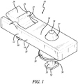
- FIGS. 1-4 show a fastener system 10 in accordance with a preferred embodiment of the present invention.
- the fastener system 10 generally includes a female fastener assembly 12 and a male fastener assembly 36.
- the female fastener assembly 12 includes a housing 14 and a switch member 22, and the male fastener assembly 36 includes a post 38 having a slot 40 defined therein.
- the housing 14 has an upper surface 16 and a lower surface 18.
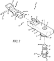
- FIG. 2 is an exploded perspective view of a preferred embodiment of the fastener system 10.
- the housing 14 has a channel 20 defined therein and a lower opening 30 defined therein that extends through the lower surface 18 and is in communication with the channel 20.
- the housing 14 also preferably includes an upper opening 31 that extends through the upper surface 16.
- the female fastener assembly 12 includes the switch member 22, which includes a switch portion 28, a neck portion 23 and a receiver portion 24.
- the receiver portion 24 has a post opening 26 defined therein.
- the post opening 26 includes a fastening portion 32 and a removing portion 34.
- the switch member 22 is movable or slidable within the channel 20.
- the switch portion 28 includes an engagement portion 25 in a preferred embodiment.
- the post 38 is cylindrical and includes the slot 40 extending circumferentially therearound.
- the slot 40 may only extend partially around the post 38.
- the post 38 can be another shape, such as square or rectangular and the slot 40 can be a notch. As described below, the slot 40 captures a portion of the receiver portion 24, when the switch member 22 is moved to the fastening position.
- the post 38 may have an inclined surface 37 and the lower opening 30 may be a self-aligning opening that includes an inclined surface 39 that cooperates with inclined surface 37, such that even if the post 38 is not inserted directly into the center of the lower opening 30, the inclined surface 29 will guide the post 38 into the lower opening 30.
- FIGS. 3A and 3B show a preferred embodiment in which the fastener system 10 is used to join a first panel 42 and a second panel 44.
- the female fastener assembly 12 is secured to the first panel 42 and the male fastener assembly 36 is secured to the second panel 44.
- Any method for securing the female fastener assembly 12 to the first panel 42 and the male fastener assembly 36 to the second panel 44 is within the scope of the present invention.
- glue, adhesive, welding, threaded fasteners, rivets or the like can be used.
- the female fastener assembly 12 includes inserts 50 extending outwardly from the housing 14.
- the male fastener assembly 36 also includes an insert 50 extending therefrom.
- the inserts 50 are inserted into openings 54 defined in the first and second panels 42 and 44 and are adhered or potted therein.
- the inserts 50 can include lower flanges 52 thereon that help secure the inserts 50 within the openings 54.
- the inserts 50 can also include a middle or upper flange 56.
- FIG. 3B shows a preferred embodiment of the fastener system 10 in the removing position.
- the post 38 of the male fastener assembly 36 can be freely inserted through the lower opening 30 of the housing 14 and through the removing portion 34 of the post opening 26 of the switch member 22 (and through the upper opening 31).
- the post 38 of the male fastener assembly 36 can be freely disengaged from the female fastener assembly 12 by removing the post 38 from the removing portion 34 of the post opening 26 of the switch member 22 and the lower opening 30 of the housing 14.
- FIG. 3B shows a preferred embodiment of the fastener system 10 in the removing position.
- the slot 40 of the post 38 does not receive any portion of the receiver portion 24 of the switch member 22.
- the switch member 22 moves within the channel 20 of the housing 14.
- FIG. 3A shows a preferred embodiment of the fastener system 10 in the fastening position.
- the post 38 of the male fastener assembly 36 extends through the lower opening 30 of the housing 14 and through the post opening 26 of the switch member 22.
- the slot 40 of the post 38 is aligned with the channel 20 and receives a portion of the receiver portion 24 of the switch member 22, thus preventing the post 38 from being removed from the post opening 26.
- the fastening portion 32 of the post opening 26 has a smaller width or diameter than the post 38. Therefore, a portion of the receiver portion 24 is captured in the slot 40.
- the switch portion 28 is spring biased upwardly.
- the switch portion includes a shaft 46 that extends beyond at least one side thereof.
- the shaft 46 extends through an opening 47 in the switch portion 28 and extends outwardly from both sides thereof.
- the housing 14 also includes at least one and preferably two slots 48 defined therein that is in communication with the channel 20.
- an upwardly spring-biased switch portion 28 in conjunction with a slot 48 in the housing 14 is merely exemplary and that other methods of securing the switch member 22 in the fastening position may be used in accordance with the present invention.
- a spring could be used within the channel 20 that exerts a horizontal force on the switch member 22, or adhesives could be used to hold the switch member 22 in the fastening position.
- FIG. 4 shows an end elevational view of a preferred embodiment of the present invention as viewed from the end of the switch member 22.
- FIG. 4 shows a preferred embodiment in which the switch portion 28 of the switch member 22 protrudes beyond the upper surface 16 of the housing 14.
- the female fastener assembly 12 is secured to a first panel 42 and the male fastener assembly 14 is secured to a second panel.
- the switch member 22 is positioned in the removing position and the post 38 is inserted through the opening 54 in the first panel 42, through lower opening 30 and through the receiving portion 34 of the post opening 26.
- the switch member 22 (and shaft 46) are then moved within the channel 20 to the fastening position. Because the switch portion 28 is biased upwardly, when the opposite ends of the shaft 46 reach the slots 48, the opposite ends of the shaft 46 are forced into the slots 48, thereby securing the switch member 22 in the fastening position.
- the fastening portion 32 of the post opening is simultaneously aligned with the post 38 and a portion of the receiver portion 24 is received in slot 40.
- the switch portion 28 is pushed downwardly so that the opposite ends of the shaft 46 come out of slots 48 and inwardly so that the opposite ends of the shaft 46 slide along channel 20 (as shown in FIG. 4 ) until the switch portion 28 is in the removing position.
- the receiving portion 34 of the post opening 26 is aligned with the post 38. This allows the post 38 to be pulled out of the post opening 26, the lower opening 30 and the opening 54 in the first panel 42.
Landscapes
- Engineering & Computer Science (AREA)
- General Engineering & Computer Science (AREA)
- Mechanical Engineering (AREA)
- Aviation & Aerospace Engineering (AREA)
- Connection Of Plates (AREA)
- Switch Cases, Indication, And Locking (AREA)
- Insertion Pins And Rivets (AREA)
Claims (13)
- Befestigungssystem (10) zum Verbinden eines ersten Gegenstandes (42) und eines zweiten Gegenstandes (44), wobei das Befestigungssystem Folgendes umfasst:
eine Aufnahmebefestigungsbaugruppe (12), die ein Gehäuse (14) einschließt, das eine obere Fläche (16), eine untere Fläche (18) und einen Kanal (20), der darin definiert ist, aufweist, wobei die Aufnahmebefestigungsbaugruppe ferner ein Umschaltelement (22) umfasst, das innerhalb des Kanals in dem Gehäuse zwischen einer Entfernungsstellung und einer Befestigungsstellung beweglich ist, wobei das Umschaltelement einen Aufnahmeabschnitt (24), der eine Pfostenöffnung (26) aufweist, die darin definiert ist, und einen Umschaltabschnitt (28) einschließt, wobei das Gehäuse eine untere Öffnung (30) aufweist, die darin definiert ist, die sich durch die untere Fläche desselben erstreckt und in Verbindung mit dem Kanal steht, wobei die Pfostenöffnung einen Befestigungsabschnitt (32) und einen Entfernungsabschnitt (34) einschließt, wobei der Entfernungsabschnitt mit der unteren Öffnung ausgerichtet ist, wenn sich das Umschaltelement in der Entfernungsstellung befindet, und der Befestigungsabschnitt mit der unteren Öffnung ausgerichtet ist, wenn sich das Umschaltelement in der Befestigungsstellung befindet, und eine Einsteckbefestigungsbaugruppe (36), die einen Pfosten (38) einschließt, der einen Schlitz (40) aufweist, der darin definiert ist, wobei mindestens ein Abschnitt des Pfostens derart durch die untere Öffnung in dem Gehäuse und die Pfostenöffnung aufgenommen wird, dass der Schlitz mit dem Kanal ausgerichtet ist, und wobei der Schlitz einen Abschnitt des Aufnahmeabschnitts aufnimmt, wenn sich das Umschaltelement in der Befestigungsstellung befindet, wobei der Umschaltabschnitt nach oben federvorgespannt ist. - Befestigungssystem (10) nach Anspruch 1, wobei der Umschaltabschnitt (28) einen Schaft (46) einschließt, der sich von mindestens einer Seite desselben aus nach außen erstreckt, wobei das Gehäuse (14) einen Schlitz (48) aufweist, der darin definiert ist, der in Verbindung mit dem Kanal (20) steht, und wobei der Schaft in dem Schlitz aufgenommen wird, wenn sich das Umschaltelement in der Befestigungsstellung befindet.
- Befestigungssystem (10) nach Anspruch 1, wobei die untere Öffnung (30) des Gehäuses (14) eine selbstausrichtende Öffnung ist und mindestens teilweise durch eine geneigte Fläche (39) definiert ist, wodurch, wenn der Pfosten (38) in die untere Öffnung (30) eingesetzt wird, die geneigte Fläche den Pfosten in die untere Öffnung leitet.
- Befestigungssystem (10) nach Anspruch 3, wobei der Pfosten (38) eine geneigte Fläche (37) einschließt, welche die geneigte Fläche (39) des Gehäuses (14) in Eingriff nimmt, wenn der Pfosten in die untere Öffnung (30) eingesetzt wird.
- Befestigungssystem (10) nach Anspruch 1, wobei der Entfernungsabschnitt (34) der Pfostenöffnung (26) eine Breite aufweist, die breiter ist als eine Breite des Befestigungsabschnitts (32) der Pfostenöffnung.
- Befestigungssystem (10) nach Anspruch 5, wobei der Pfosten (38) einen Durchmesser aufweist, der kleiner ist als die Breite des Entfernungsabschnitts (34) der Pfostenöffnung (26) und eine Breite der unteren Öffnung (30) des Gehäuses (14).
- Befestigungssystem (10) nach Anspruch 1, wobei die Einsteckbefestigungsbaugruppe (36) einen Einsatz (50) einschließt, der sich von dem Pfosten (38) aus nach unten erstreckt.
- Verfahren zum Verbinden eines ersten Gegenstandes (42), der eine Aufnahmebefestigungsbaugruppe (12) aufweist, die an demselben befestigt ist, mit einem zweiten Gegenstand, der eine Einsteckbefestigungsbaugruppe (36) aufweist, die an demselben befestigt ist, wobei das Verfahren die folgenden Schritte umfasst:(a) Einsetzen eines Pfostens (38) der Einsteckbefestigungsbaugruppe durch eine Öffnung in dem ersten Gegenstand, eine untere Öffnung (30) eines Gehäuses (14) der Aufnahmebefestigungsbaugruppe und eine Pfostenöffnung (26) in einem Umschaltelement (22), wobei das Umschaltelement einen Umschaltabschnitt (28) und einen Aufnahmeabschnitt (24) einschließt, und wobei die Pfostenöffnung in dem Aufnahmeabschnitt definiert ist,(b) Bewegen des Umschaltelements innerhalb eines Kanals (20), der in dem Gehäuse definiert ist, von einer Entfernungsstellung zu einer Befestigungsstellung derart, dass ein Schlitz (40), der in dem Pfosten definiert ist, einen Abschnitt des Aufnahmeabschnitts aufnimmt, wobei der Umschaltabschnitt nach oben federvorgespannt ist.
- Verfahren nach Anspruch 8, wobei, wenn das Umschaltelement (22) zu der Befestigungsstellung bewegt wird, sich der Umschaltabschnitt (28) derart nach oben bewegt, dass ein Schaft (46), der mit dem Umschaltabschnitt verknüpft ist, in einem Schlitz (48) aufgenommen wird, der in dem Gehäuse (14) definiert ist.
- Verfahren nach Anspruch 8, wobei die untere Öffnung (30) des Gehäuses (14) eine selbstausrichtende Öffnung ist und mindestens teilweise durch eine geneigte Fläche (39) definiert ist, wodurch, wenn der Pfosten (38) in die untere Öffnung eingesetzt wird, die geneigte Fläche den Pfosten in die untere Öffnung leitet.
- Verfahren nach Anspruch 10, wobei der Pfosten (38) eine geneigte Fläche (37) einschließt, welche die geneigte Fläche (39) des Gehäuses (14) in Eingriff nimmt, wenn der Pfosten in die untere Öffnung (30) eingesetzt wird.
- Befestigungssystem (10) nach Anspruch 1, das ferner Folgendes umfasst:den ersten Gegenstand (42), der eine Öffnung aufweist, die darin definiert ist, wobei die Aufnahmebefestigungsbaugruppe (12) an dem ersten Gegenstand befestigt ist und wobei die untere Öffnung (30) mit der Öffnung in dem ersten Gegenstand ausgerichtet ist, undden zweiten Gegenstand (44), wobei die Einsteckbefestigungsbaugruppe (36) an dem zweiten Gegenstand befestigt ist, undwobei mindestens ein Abschnitt des Pfostens (38) durch die Öffnung in dem ersten Gegenstand aufgenommen wird.
- Befestigungssystem (10) nach Anspruch 12, wobei die Einsteckbefestigungsbaugruppe (36) einen Einsatz (50) einschließt, der sich von dem Pfosten (38) aus nach unten erstreckt, der in einer Öffnung in dem zweiten Gegenstand (44) aufgenommen und gesichert wird.
Applications Claiming Priority (3)
| Application Number | Priority Date | Filing Date | Title |
|---|---|---|---|
| US201461971495P | 2014-03-27 | 2014-03-27 | |
| US201462009762P | 2014-06-09 | 2014-06-09 | |
| PCT/US2015/022522 WO2015148690A1 (en) | 2014-03-27 | 2015-03-25 | Fastener system |
Publications (3)
| Publication Number | Publication Date |
|---|---|
| EP3122625A1 EP3122625A1 (de) | 2017-02-01 |
| EP3122625A4 EP3122625A4 (de) | 2018-02-07 |
| EP3122625B1 true EP3122625B1 (de) | 2020-07-29 |
Family
ID=54196356
Family Applications (1)
| Application Number | Title | Priority Date | Filing Date |
|---|---|---|---|
| EP15770358.8A Active EP3122625B1 (de) | 2014-03-27 | 2015-03-25 | Befestigungssystem |
Country Status (5)
| Country | Link |
|---|---|
| US (2) | US9562549B2 (de) |
| EP (1) | EP3122625B1 (de) |
| CN (2) | CN106132822B (de) |
| RU (1) | RU2679976C2 (de) |
| WO (1) | WO2015148690A1 (de) |
Families Citing this family (23)
| Publication number | Priority date | Publication date | Assignee | Title |
|---|---|---|---|---|
| CN104482005B (zh) * | 2014-12-12 | 2017-08-15 | 深圳利亚德光电有限公司 | 连接装置及具有其的显示屏 |
| DE102015013229A1 (de) * | 2015-10-14 | 2017-04-20 | Rheinisch-Westfälische Technische Hochschule (Rwth) Aachen | Pfosten-Träger-Verbindung und Verfahren zu deren Herstellung |
| US10711442B2 (en) | 2016-04-26 | 2020-07-14 | Kohler Co. | Composite faucet body and internal waterway |
| EP3348288A3 (de) | 2017-01-13 | 2018-10-24 | M.M.A. Tech, Ltd. | Verbesserte knochenfixiervorrichtungen |
| CN116280158A (zh) * | 2017-03-30 | 2023-06-23 | 赛峰客舱公司 | 侧壁面板组件 |
| US11118338B2 (en) | 2017-05-22 | 2021-09-14 | Kohler Co. | Plumbing fixtures with insert-molded components |
| BR102018010327B1 (pt) | 2017-05-22 | 2023-12-12 | Kohler Co | Montagem de vaso sanitário e acessório de encanamento |
| US10744419B2 (en) * | 2017-06-09 | 2020-08-18 | Qun Xia | Modular panel interlocking and reinforcing mechanism for building enclosures |
| DE102018102456A1 (de) * | 2018-02-05 | 2019-08-08 | Eberspächer Exhaust Technology GmbH & Co. KG | Schnellwechselkupplung |
| US10779662B2 (en) * | 2018-08-09 | 2020-09-22 | Shenzhen X-Live Electronics Co., Ltd. | Display rack for display and exhibition and display device |
| CN110821926B (zh) * | 2018-08-10 | 2022-11-22 | 康普技术有限责任公司 | 用于板状元件的紧固件以及板状元件系统 |
| CN109649635A (zh) * | 2018-11-02 | 2019-04-19 | 中国航空工业集团公司西安飞机设计研究所 | 一种飞机隔声隔热层安装方法 |
| TWI693351B (zh) * | 2018-12-22 | 2020-05-11 | 伍鐌科技股份有限公司 | 滑動定位結構 |
| CN109571437B (zh) * | 2018-12-25 | 2022-10-18 | 江南大学 | 一种单目摄像的机器人 |
| USD973734S1 (en) * | 2019-08-06 | 2022-12-27 | Nxl Technologies Inc. | Blind shear |
| US20210078707A1 (en) | 2019-09-18 | 2021-03-18 | Safran Cabin Inc. | Aircraft with configurable divider system |
| US20210078703A1 (en) | 2019-09-18 | 2021-03-18 | Safran Cabin Inc. | Aircraft interior with modular panels |
| US20210078709A1 (en) | 2019-09-18 | 2021-03-18 | Safran Cabin Inc. | Aircraft interior with removable panels |
| EP3828424B1 (de) * | 2019-11-29 | 2023-06-28 | Illinois Tool Works Inc. | Befestigungsvorrichtung |
| CN114060374B (zh) * | 2020-08-07 | 2023-10-03 | 光宝电子(广州)有限公司 | 固定装置 |
| CN112026493B (zh) * | 2020-08-18 | 2022-03-29 | 福耀玻璃工业集团股份有限公司 | 一种带有饰条的包边玻璃总成 |
| CN113389789A (zh) * | 2021-02-07 | 2021-09-14 | 机械工业第九设计研究院有限公司 | 一种便捷式过滤器锁紧器结构 |
| EP4086466B1 (de) * | 2021-05-06 | 2024-03-13 | Illinois Tool Works Inc. | Befestigungsvorrichtung |
Family Cites Families (36)
| Publication number | Priority date | Publication date | Assignee | Title |
|---|---|---|---|---|
| US2668724A (en) * | 1952-03-18 | 1954-02-09 | Aero Smith Inc | Fastening device |
| FR1061188A (fr) * | 1952-08-04 | 1954-04-09 | Carbodies Ltd | Dispositif de montage d'un objet allongé tel qu'un boulon ou un pivot notamment surune membrure de caisse d'automobile |
| US3538940A (en) * | 1967-09-15 | 1970-11-10 | Gra Tec Inc | Fitting assembly |
| US3727160A (en) * | 1972-03-24 | 1973-04-10 | Automatic Switch Co | Retaining clip for a solenoid assembly |
| US3999055A (en) * | 1974-10-04 | 1976-12-21 | Nippon Kogaku K.K. | Mounting device for mounting a flashlight unit to a camera body |
| JPS5943544Y2 (ja) * | 1979-01-22 | 1984-12-25 | 道雄 川添 | カメラ取付用ブラケツトの保持装置 |
| US4352586A (en) * | 1980-12-29 | 1982-10-05 | Ford Motor Company | Linkage system |
| US4683453A (en) * | 1985-11-25 | 1987-07-28 | Automatic Switch Company | Solenoid actuator with fastener |
| US4971492A (en) * | 1989-05-02 | 1990-11-20 | Moyer Donald L | Wheel strap snap hanger with flexible fingers |
| US5000614A (en) | 1989-05-05 | 1991-03-19 | Huron Products Corporation | Conduit quick connector assembly having a ramped housing with a hair pin retainer |
| JPH0629428U (ja) * | 1992-08-12 | 1994-04-19 | 吉田工業株式会社 | 係止具 |
| JPH07151132A (ja) * | 1993-11-30 | 1995-06-13 | Nippon Cable Syst Inc | クリップ付き軸端座金およびそれを用いた連結構造 |
| DE19517010C2 (de) * | 1995-05-10 | 1998-03-19 | Prym William Gmbh & Co Kg | Druckknopfverschluß |
| US5704100A (en) * | 1996-03-01 | 1998-01-06 | Federal-Hoffman, Inc. | Retaining clip system |
| US5964483A (en) * | 1997-11-19 | 1999-10-12 | Dayco Products, Inc. | Fluid coupling assembly, locking member therefor, and method of assembly |
| DE19801343A1 (de) * | 1998-01-16 | 1999-07-22 | United Parts Fhs Automobil Sys | Schnellbefestigungssystem für Betätigungszüge und Feder |
| US5937705A (en) * | 1998-04-08 | 1999-08-17 | Flex Technologies, Inc. | Push-pull control cable assembly with quick-release terminal fittings therefor |
| GB2354795A (en) * | 1999-09-29 | 2001-04-04 | Silicone Altimex Ltd | Oven door catch |
| US6505387B1 (en) * | 2000-09-25 | 2003-01-14 | Cray Inc. | Flexible fastener |
| US6557220B1 (en) * | 2002-05-31 | 2003-05-06 | B. A. Ballou & Co., Inc. | Security clutch with self-centering spring |
| RU2260148C2 (ru) * | 2003-12-03 | 2005-09-10 | Открытое акционерное общество "ГАЗ" | Быстроразъемное соединение деталей |
| US7128514B1 (en) * | 2005-04-08 | 2006-10-31 | Yazaki North America, Inc. | Adjustable and reusable stud bolt retainer |
| CA2509095C (en) | 2005-06-03 | 2015-01-20 | Armatec Survivability Corp. | Armor mounting system |
| DE102005037825B3 (de) | 2005-08-08 | 2007-03-15 | Demag Cranes & Components Gmbh | Anordnung zur axialen Sicherung eines mit einer Nut versehenen Bolzens |
| JP4646756B2 (ja) * | 2005-09-20 | 2011-03-09 | 株式会社パイオラックス | シャフト固定構造 |
| DE102006002565A1 (de) * | 2006-01-05 | 2007-07-12 | Alfred Kärcher Gmbh & Co. Kg | Kupplungsteil für Steckverbinderanordnung |
| US7527223B2 (en) | 2006-04-06 | 2009-05-05 | The Boeing Company | Interior panel attachment system |
| CN1834478A (zh) * | 2006-04-06 | 2006-09-20 | 韩德第 | 健身器连接装置 |
| DE202007019243U1 (de) * | 2007-12-21 | 2011-04-28 | Sfs Intec Holding Ag | Steckhalterung |
| US8221043B2 (en) * | 2008-02-18 | 2012-07-17 | Lockheed Martin Corporation | Releasable fastener systems and methods |
| GB2460641B (en) * | 2008-06-02 | 2013-03-13 | Joy Mm Delaware Inc | A clip for pin retention |
| DE102009008188B4 (de) * | 2009-02-10 | 2011-06-30 | Airbus Operations GmbH, 21129 | Befestigungsvorrichtung für ein Modulelement in einem Flugzeug und Befestigungssystem |
| US8632054B2 (en) * | 2011-02-23 | 2014-01-21 | Honeywell International Inc. | Valve actuator assembly with tool-less interconnect |
| US9353779B2 (en) * | 2011-11-16 | 2016-05-31 | Ford Global Technologies, Llc | Molded encapsulated retainer |
| CN202883582U (zh) * | 2012-04-28 | 2013-04-17 | 康扬企业股份有限公司 | 间隔柱 |
| CN202914461U (zh) * | 2012-10-15 | 2013-05-01 | 恒昌行精密工业有限公司 | 板对板快速定位装置 |
-
2015
- 2015-03-25 RU RU2016141957A patent/RU2679976C2/ru active
- 2015-03-25 US US14/668,627 patent/US9562549B2/en active Active
- 2015-03-25 CN CN201580016619.4A patent/CN106132822B/zh active Active
- 2015-03-25 WO PCT/US2015/022522 patent/WO2015148690A1/en active Application Filing
- 2015-03-25 EP EP15770358.8A patent/EP3122625B1/de active Active
- 2015-03-25 CN CN201811082273.XA patent/CN109178288B/zh active Active
-
2017
- 2017-01-05 US US15/399,609 patent/US9638233B1/en not_active Expired - Fee Related
Non-Patent Citations (1)
| Title |
|---|
| None * |
Also Published As
| Publication number | Publication date |
|---|---|
| EP3122625A4 (de) | 2018-02-07 |
| CN106132822B (zh) | 2019-01-01 |
| US20150354610A1 (en) | 2015-12-10 |
| EP3122625A1 (de) | 2017-02-01 |
| CN109178288A (zh) | 2019-01-11 |
| RU2016141957A (ru) | 2018-04-27 |
| US20170114817A1 (en) | 2017-04-27 |
| CN106132822A (zh) | 2016-11-16 |
| CN109178288B (zh) | 2022-03-01 |
| RU2679976C2 (ru) | 2019-02-14 |
| US9638233B1 (en) | 2017-05-02 |
| US9562549B2 (en) | 2017-02-07 |
| RU2016141957A3 (de) | 2018-08-20 |
| WO2015148690A1 (en) | 2015-10-01 |
Similar Documents
| Publication | Publication Date | Title |
|---|---|---|
| US9638233B1 (en) | Fastener system | |
| US9045230B2 (en) | Lavatory Monument Assembly | |
| US9079668B2 (en) | Integrated lavatory galley monument | |
| EP3064784B1 (de) | Plattensystem und montageverfahren für ein plattensystem | |
| US20130206905A1 (en) | Integrated galley and bin monument | |
| US10781607B2 (en) | Handle load transfer insert for panels | |
| CA2974831C (en) | Ceiling panel assembly and mounting system therefor | |
| US10723460B2 (en) | Toilet module attachment assembly and method of use | |
| US9567082B2 (en) | Attachment assembly for a toilet module | |
| CA3003753C (en) | Storage bin with luggage positioning protrusions | |
| CA2996029C (en) | Toilet module | |
| WO2020097219A1 (en) | Reconfigurable aircraft galley monument |
Legal Events
| Date | Code | Title | Description |
|---|---|---|---|
| STAA | Information on the status of an ep patent application or granted ep patent |
Free format text: STATUS: THE INTERNATIONAL PUBLICATION HAS BEEN MADE |
|
| PUAI | Public reference made under article 153(3) epc to a published international application that has entered the european phase |
Free format text: ORIGINAL CODE: 0009012 |
|
| STAA | Information on the status of an ep patent application or granted ep patent |
Free format text: STATUS: REQUEST FOR EXAMINATION WAS MADE |
|
| 17P | Request for examination filed |
Effective date: 20160923 |
|
| AK | Designated contracting states |
Kind code of ref document: A1 Designated state(s): AL AT BE BG CH CY CZ DE DK EE ES FI FR GB GR HR HU IE IS IT LI LT LU LV MC MK MT NL NO PL PT RO RS SE SI SK SM TR |
|
| AX | Request for extension of the european patent |
Extension state: BA ME |
|
| DAV | Request for validation of the european patent (deleted) | ||
| DAX | Request for extension of the european patent (deleted) | ||
| A4 | Supplementary search report drawn up and despatched |
Effective date: 20180109 |
|
| RIC1 | Information provided on ipc code assigned before grant |
Ipc: F16B 21/09 20060101ALI20180103BHEP Ipc: F16B 21/06 20060101ALI20180103BHEP Ipc: F16B 5/06 20060101ALI20180103BHEP Ipc: B64C 1/00 20060101AFI20180103BHEP |
|
| GRAP | Despatch of communication of intention to grant a patent |
Free format text: ORIGINAL CODE: EPIDOSNIGR1 |
|
| STAA | Information on the status of an ep patent application or granted ep patent |
Free format text: STATUS: GRANT OF PATENT IS INTENDED |
|
| INTG | Intention to grant announced |
Effective date: 20200306 |
|
| GRAS | Grant fee paid |
Free format text: ORIGINAL CODE: EPIDOSNIGR3 |
|
| GRAA | (expected) grant |
Free format text: ORIGINAL CODE: 0009210 |
|
| STAA | Information on the status of an ep patent application or granted ep patent |
Free format text: STATUS: THE PATENT HAS BEEN GRANTED |
|
| AK | Designated contracting states |
Kind code of ref document: B1 Designated state(s): AL AT BE BG CH CY CZ DE DK EE ES FI FR GB GR HR HU IE IS IT LI LT LU LV MC MK MT NL NO PL PT RO RS SE SI SK SM TR |
|
| REG | Reference to a national code |
Ref country code: CH Ref legal event code: EP |
|
| REG | Reference to a national code |
Ref country code: AT Ref legal event code: REF Ref document number: 1295480 Country of ref document: AT Kind code of ref document: T Effective date: 20200815 |
|
| REG | Reference to a national code |
Ref country code: IE Ref legal event code: FG4D |
|
| REG | Reference to a national code |
Ref country code: DE Ref legal event code: R096 Ref document number: 602015056542 Country of ref document: DE |
|
| REG | Reference to a national code |
Ref country code: LT Ref legal event code: MG4D |
|
| REG | Reference to a national code |
Ref country code: NL Ref legal event code: MP Effective date: 20200729 |
|
| REG | Reference to a national code |
Ref country code: AT Ref legal event code: MK05 Ref document number: 1295480 Country of ref document: AT Kind code of ref document: T Effective date: 20200729 |
|
| PG25 | Lapsed in a contracting state [announced via postgrant information from national office to epo] |
Ref country code: BG Free format text: LAPSE BECAUSE OF FAILURE TO SUBMIT A TRANSLATION OF THE DESCRIPTION OR TO PAY THE FEE WITHIN THE PRESCRIBED TIME-LIMIT Effective date: 20201029 Ref country code: ES Free format text: LAPSE BECAUSE OF FAILURE TO SUBMIT A TRANSLATION OF THE DESCRIPTION OR TO PAY THE FEE WITHIN THE PRESCRIBED TIME-LIMIT Effective date: 20200729 Ref country code: GR Free format text: LAPSE BECAUSE OF FAILURE TO SUBMIT A TRANSLATION OF THE DESCRIPTION OR TO PAY THE FEE WITHIN THE PRESCRIBED TIME-LIMIT Effective date: 20201030 Ref country code: LT Free format text: LAPSE BECAUSE OF FAILURE TO SUBMIT A TRANSLATION OF THE DESCRIPTION OR TO PAY THE FEE WITHIN THE PRESCRIBED TIME-LIMIT Effective date: 20200729 Ref country code: AT Free format text: LAPSE BECAUSE OF FAILURE TO SUBMIT A TRANSLATION OF THE DESCRIPTION OR TO PAY THE FEE WITHIN THE PRESCRIBED TIME-LIMIT Effective date: 20200729 Ref country code: HR Free format text: LAPSE BECAUSE OF FAILURE TO SUBMIT A TRANSLATION OF THE DESCRIPTION OR TO PAY THE FEE WITHIN THE PRESCRIBED TIME-LIMIT Effective date: 20200729 Ref country code: NO Free format text: LAPSE BECAUSE OF FAILURE TO SUBMIT A TRANSLATION OF THE DESCRIPTION OR TO PAY THE FEE WITHIN THE PRESCRIBED TIME-LIMIT Effective date: 20201029 Ref country code: PT Free format text: LAPSE BECAUSE OF FAILURE TO SUBMIT A TRANSLATION OF THE DESCRIPTION OR TO PAY THE FEE WITHIN THE PRESCRIBED TIME-LIMIT Effective date: 20201130 Ref country code: SE Free format text: LAPSE BECAUSE OF FAILURE TO SUBMIT A TRANSLATION OF THE DESCRIPTION OR TO PAY THE FEE WITHIN THE PRESCRIBED TIME-LIMIT Effective date: 20200729 Ref country code: FI Free format text: LAPSE BECAUSE OF FAILURE TO SUBMIT A TRANSLATION OF THE DESCRIPTION OR TO PAY THE FEE WITHIN THE PRESCRIBED TIME-LIMIT Effective date: 20200729 |
|
| PG25 | Lapsed in a contracting state [announced via postgrant information from national office to epo] |
Ref country code: RS Free format text: LAPSE BECAUSE OF FAILURE TO SUBMIT A TRANSLATION OF THE DESCRIPTION OR TO PAY THE FEE WITHIN THE PRESCRIBED TIME-LIMIT Effective date: 20200729 Ref country code: LV Free format text: LAPSE BECAUSE OF FAILURE TO SUBMIT A TRANSLATION OF THE DESCRIPTION OR TO PAY THE FEE WITHIN THE PRESCRIBED TIME-LIMIT Effective date: 20200729 Ref country code: PL Free format text: LAPSE BECAUSE OF FAILURE TO SUBMIT A TRANSLATION OF THE DESCRIPTION OR TO PAY THE FEE WITHIN THE PRESCRIBED TIME-LIMIT Effective date: 20200729 Ref country code: IS Free format text: LAPSE BECAUSE OF FAILURE TO SUBMIT A TRANSLATION OF THE DESCRIPTION OR TO PAY THE FEE WITHIN THE PRESCRIBED TIME-LIMIT Effective date: 20201129 |
|
| PG25 | Lapsed in a contracting state [announced via postgrant information from national office to epo] |
Ref country code: NL Free format text: LAPSE BECAUSE OF FAILURE TO SUBMIT A TRANSLATION OF THE DESCRIPTION OR TO PAY THE FEE WITHIN THE PRESCRIBED TIME-LIMIT Effective date: 20200729 |
|
| PG25 | Lapsed in a contracting state [announced via postgrant information from national office to epo] |
Ref country code: CZ Free format text: LAPSE BECAUSE OF FAILURE TO SUBMIT A TRANSLATION OF THE DESCRIPTION OR TO PAY THE FEE WITHIN THE PRESCRIBED TIME-LIMIT Effective date: 20200729 Ref country code: DK Free format text: LAPSE BECAUSE OF FAILURE TO SUBMIT A TRANSLATION OF THE DESCRIPTION OR TO PAY THE FEE WITHIN THE PRESCRIBED TIME-LIMIT Effective date: 20200729 Ref country code: IT Free format text: LAPSE BECAUSE OF FAILURE TO SUBMIT A TRANSLATION OF THE DESCRIPTION OR TO PAY THE FEE WITHIN THE PRESCRIBED TIME-LIMIT Effective date: 20200729 Ref country code: EE Free format text: LAPSE BECAUSE OF FAILURE TO SUBMIT A TRANSLATION OF THE DESCRIPTION OR TO PAY THE FEE WITHIN THE PRESCRIBED TIME-LIMIT Effective date: 20200729 Ref country code: RO Free format text: LAPSE BECAUSE OF FAILURE TO SUBMIT A TRANSLATION OF THE DESCRIPTION OR TO PAY THE FEE WITHIN THE PRESCRIBED TIME-LIMIT Effective date: 20200729 Ref country code: SM Free format text: LAPSE BECAUSE OF FAILURE TO SUBMIT A TRANSLATION OF THE DESCRIPTION OR TO PAY THE FEE WITHIN THE PRESCRIBED TIME-LIMIT Effective date: 20200729 |
|
| REG | Reference to a national code |
Ref country code: DE Ref legal event code: R097 Ref document number: 602015056542 Country of ref document: DE |
|
| PG25 | Lapsed in a contracting state [announced via postgrant information from national office to epo] |
Ref country code: AL Free format text: LAPSE BECAUSE OF FAILURE TO SUBMIT A TRANSLATION OF THE DESCRIPTION OR TO PAY THE FEE WITHIN THE PRESCRIBED TIME-LIMIT Effective date: 20200729 |
|
| PLBE | No opposition filed within time limit |
Free format text: ORIGINAL CODE: 0009261 |
|
| STAA | Information on the status of an ep patent application or granted ep patent |
Free format text: STATUS: NO OPPOSITION FILED WITHIN TIME LIMIT |
|
| PG25 | Lapsed in a contracting state [announced via postgrant information from national office to epo] |
Ref country code: SK Free format text: LAPSE BECAUSE OF FAILURE TO SUBMIT A TRANSLATION OF THE DESCRIPTION OR TO PAY THE FEE WITHIN THE PRESCRIBED TIME-LIMIT Effective date: 20200729 |
|
| 26N | No opposition filed |
Effective date: 20210430 |
|
| PG25 | Lapsed in a contracting state [announced via postgrant information from national office to epo] |
Ref country code: SI Free format text: LAPSE BECAUSE OF FAILURE TO SUBMIT A TRANSLATION OF THE DESCRIPTION OR TO PAY THE FEE WITHIN THE PRESCRIBED TIME-LIMIT Effective date: 20200729 |
|
| REG | Reference to a national code |
Ref country code: DE Ref legal event code: R119 Ref document number: 602015056542 Country of ref document: DE |
|
| PG25 | Lapsed in a contracting state [announced via postgrant information from national office to epo] |
Ref country code: MC Free format text: LAPSE BECAUSE OF FAILURE TO SUBMIT A TRANSLATION OF THE DESCRIPTION OR TO PAY THE FEE WITHIN THE PRESCRIBED TIME-LIMIT Effective date: 20200729 |
|
| REG | Reference to a national code |
Ref country code: CH Ref legal event code: PL |
|
| GBPC | Gb: european patent ceased through non-payment of renewal fee |
Effective date: 20210325 |
|
| REG | Reference to a national code |
Ref country code: BE Ref legal event code: MM Effective date: 20210331 |
|
| PG25 | Lapsed in a contracting state [announced via postgrant information from national office to epo] |
Ref country code: DE Free format text: LAPSE BECAUSE OF NON-PAYMENT OF DUE FEES Effective date: 20211001 Ref country code: FR Free format text: LAPSE BECAUSE OF NON-PAYMENT OF DUE FEES Effective date: 20210331 Ref country code: GB Free format text: LAPSE BECAUSE OF NON-PAYMENT OF DUE FEES Effective date: 20210325 Ref country code: IE Free format text: LAPSE BECAUSE OF NON-PAYMENT OF DUE FEES Effective date: 20210325 Ref country code: CH Free format text: LAPSE BECAUSE OF NON-PAYMENT OF DUE FEES Effective date: 20210331 Ref country code: LU Free format text: LAPSE BECAUSE OF NON-PAYMENT OF DUE FEES Effective date: 20210325 Ref country code: LI Free format text: LAPSE BECAUSE OF NON-PAYMENT OF DUE FEES Effective date: 20210331 |
|
| PG25 | Lapsed in a contracting state [announced via postgrant information from national office to epo] |
Ref country code: BE Free format text: LAPSE BECAUSE OF NON-PAYMENT OF DUE FEES Effective date: 20210331 |
|
| PG25 | Lapsed in a contracting state [announced via postgrant information from national office to epo] |
Ref country code: HU Free format text: LAPSE BECAUSE OF FAILURE TO SUBMIT A TRANSLATION OF THE DESCRIPTION OR TO PAY THE FEE WITHIN THE PRESCRIBED TIME-LIMIT; INVALID AB INITIO Effective date: 20150325 |
|
| PG25 | Lapsed in a contracting state [announced via postgrant information from national office to epo] |
Ref country code: CY Free format text: LAPSE BECAUSE OF FAILURE TO SUBMIT A TRANSLATION OF THE DESCRIPTION OR TO PAY THE FEE WITHIN THE PRESCRIBED TIME-LIMIT Effective date: 20200729 |
|
| PG25 | Lapsed in a contracting state [announced via postgrant information from national office to epo] |
Ref country code: MK Free format text: LAPSE BECAUSE OF FAILURE TO SUBMIT A TRANSLATION OF THE DESCRIPTION OR TO PAY THE FEE WITHIN THE PRESCRIBED TIME-LIMIT Effective date: 20200729 |