EP3122543B1 - Faserverbundbauteil und verfahren zum herstellen eines faserverbundbauteils - Google Patents
Faserverbundbauteil und verfahren zum herstellen eines faserverbundbauteils Download PDFInfo
- Publication number
- EP3122543B1 EP3122543B1 EP15712113.8A EP15712113A EP3122543B1 EP 3122543 B1 EP3122543 B1 EP 3122543B1 EP 15712113 A EP15712113 A EP 15712113A EP 3122543 B1 EP3122543 B1 EP 3122543B1
- Authority
- EP
- European Patent Office
- Prior art keywords
- fiber
- consolidation
- region
- degree
- composite fiber
- Prior art date
- Legal status (The legal status is an assumption and is not a legal conclusion. Google has not performed a legal analysis and makes no representation as to the accuracy of the status listed.)
- Active
Links
Images

Classifications
-
- B—PERFORMING OPERATIONS; TRANSPORTING
- B29—WORKING OF PLASTICS; WORKING OF SUBSTANCES IN A PLASTIC STATE IN GENERAL
- B29C—SHAPING OR JOINING OF PLASTICS; SHAPING OF MATERIAL IN A PLASTIC STATE, NOT OTHERWISE PROVIDED FOR; AFTER-TREATMENT OF THE SHAPED PRODUCTS, e.g. REPAIRING
- B29C70/00—Shaping composites, i.e. plastics material comprising reinforcements, fillers or preformed parts, e.g. inserts
- B29C70/04—Shaping composites, i.e. plastics material comprising reinforcements, fillers or preformed parts, e.g. inserts comprising reinforcements only, e.g. self-reinforcing plastics
- B29C70/28—Shaping operations therefor
- B29C70/40—Shaping or impregnating by compression not applied
- B29C70/42—Shaping or impregnating by compression not applied for producing articles of definite length, i.e. discrete articles
- B29C70/46—Shaping or impregnating by compression not applied for producing articles of definite length, i.e. discrete articles using matched moulds, e.g. for deforming sheet moulding compounds [SMC] or prepregs
-
- B—PERFORMING OPERATIONS; TRANSPORTING
- B29—WORKING OF PLASTICS; WORKING OF SUBSTANCES IN A PLASTIC STATE IN GENERAL
- B29C—SHAPING OR JOINING OF PLASTICS; SHAPING OF MATERIAL IN A PLASTIC STATE, NOT OTHERWISE PROVIDED FOR; AFTER-TREATMENT OF THE SHAPED PRODUCTS, e.g. REPAIRING
- B29C35/00—Heating, cooling or curing, e.g. crosslinking or vulcanising; Apparatus therefor
- B29C35/02—Heating or curing, e.g. crosslinking or vulcanizing during moulding, e.g. in a mould
- B29C35/0266—Local curing
-
- B—PERFORMING OPERATIONS; TRANSPORTING
- B29—WORKING OF PLASTICS; WORKING OF SUBSTANCES IN A PLASTIC STATE IN GENERAL
- B29C—SHAPING OR JOINING OF PLASTICS; SHAPING OF MATERIAL IN A PLASTIC STATE, NOT OTHERWISE PROVIDED FOR; AFTER-TREATMENT OF THE SHAPED PRODUCTS, e.g. REPAIRING
- B29C70/00—Shaping composites, i.e. plastics material comprising reinforcements, fillers or preformed parts, e.g. inserts
- B29C70/04—Shaping composites, i.e. plastics material comprising reinforcements, fillers or preformed parts, e.g. inserts comprising reinforcements only, e.g. self-reinforcing plastics
- B29C70/28—Shaping operations therefor
- B29C70/40—Shaping or impregnating by compression not applied
- B29C70/42—Shaping or impregnating by compression not applied for producing articles of definite length, i.e. discrete articles
- B29C70/46—Shaping or impregnating by compression not applied for producing articles of definite length, i.e. discrete articles using matched moulds, e.g. for deforming sheet moulding compounds [SMC] or prepregs
- B29C70/48—Shaping or impregnating by compression not applied for producing articles of definite length, i.e. discrete articles using matched moulds, e.g. for deforming sheet moulding compounds [SMC] or prepregs and impregnating the reinforcements in the closed mould, e.g. resin transfer moulding [RTM], e.g. by vacuum
-
- B—PERFORMING OPERATIONS; TRANSPORTING
- B29—WORKING OF PLASTICS; WORKING OF SUBSTANCES IN A PLASTIC STATE IN GENERAL
- B29C—SHAPING OR JOINING OF PLASTICS; SHAPING OF MATERIAL IN A PLASTIC STATE, NOT OTHERWISE PROVIDED FOR; AFTER-TREATMENT OF THE SHAPED PRODUCTS, e.g. REPAIRING
- B29C70/00—Shaping composites, i.e. plastics material comprising reinforcements, fillers or preformed parts, e.g. inserts
- B29C70/04—Shaping composites, i.e. plastics material comprising reinforcements, fillers or preformed parts, e.g. inserts comprising reinforcements only, e.g. self-reinforcing plastics
- B29C70/28—Shaping operations therefor
- B29C70/40—Shaping or impregnating by compression not applied
- B29C70/50—Shaping or impregnating by compression not applied for producing articles of indefinite length, e.g. prepregs, sheet moulding compounds [SMC] or cross moulding compounds [XMC]
-
- C—CHEMISTRY; METALLURGY
- C08—ORGANIC MACROMOLECULAR COMPOUNDS; THEIR PREPARATION OR CHEMICAL WORKING-UP; COMPOSITIONS BASED THEREON
- C08J—WORKING-UP; GENERAL PROCESSES OF COMPOUNDING; AFTER-TREATMENT NOT COVERED BY SUBCLASSES C08B, C08C, C08F, C08G or C08H
- C08J5/00—Manufacture of articles or shaped materials containing macromolecular substances
- C08J5/04—Reinforcing macromolecular compounds with loose or coherent fibrous material
-
- B—PERFORMING OPERATIONS; TRANSPORTING
- B29—WORKING OF PLASTICS; WORKING OF SUBSTANCES IN A PLASTIC STATE IN GENERAL
- B29L—INDEXING SCHEME ASSOCIATED WITH SUBCLASS B29C, RELATING TO PARTICULAR ARTICLES
- B29L2031/00—Other particular articles
- B29L2031/22—Hinges, pivots
Definitions
- the invention relates to a fiber composite component, in particular a fiber-reinforced thermoplastic component assembly, such as an organic sheet component, and a method for producing such a fiber composite component, for example a fiber-reinforced thermoplastic component assembly.
- thermoplastic component assembly such as an organic sheet component assembly
- Fiber-reinforced thermoplastics are composite materials that consist of reinforcing fibers to absorb loads and a matrix material to ensure fiber orientation and dimensional stability.
- FVT Fiber-reinforced thermoplastics
- fiberglass, aramid fiber, carbon fiber, etc., as well as natural-based fibers such as sisal, coconut, hemp, flax, etc. can be used as fiber materials.
- Endless reinforcing fibers are generally processed as fiber strands, so-called rovings, knitted fabrics, woven fabrics or braids.
- a thermoplastic material is used as the matrix material.
- the winding technology, the pultrusion process or the interval hot-pressing technology can be used to manufacture endless, fiber-reinforced thermoplastic components in profile form.
- Flat components are now manufactured using the thermoforming process with additional back injection or extrusion, for example in an injection molding process.
- semi-finished products are usually used, which are offered in the form of partially or fully preconsolidated panels and are referred to as organic sheets or thermoplastic prepregs.
- Textile structures made of hybrid yarn, in which the reinforcing fiber and the matrix are also present in fiber form, can also be used as semi-finished products.
- the pamphlet WO 2012/032189 A2 discloses a method for producing a seat back wall for a seat back using at least one organic sheet.
- the pamphlet DE 10 2012 104 044 A1 discloses a method for at least regionally consolidating a thermoplastic preform in a molding tool.
- the pamphlet DE 10 2011 056 686 A1 discloses a method for producing a fiber composite component.
- the DE 195 31 406 A1 discloses a semi-finished product for compression molded parts.
- the EP 1 603 735 A1 describes a method for producing a connection between composite parts.
- a fiber composite component comprises at least one layer of a fiber material and a thermoplastic matrix which impregnates the fiber material, the fiber composite component having at least one first area in which the local degree of consolidation of the fiber composite component is above a first consolidation threshold value, and wherein the The fiber composite component has at least one second region, which is adjacent to the first region and in which the local degree of consolidation of the fiber composite component is below a second consolidation threshold value, the second consolidation threshold value being smaller than the first consolidation threshold value.
- the second area forms a film hinge.
- the fiber composite component comprises at least one organic sheet or a preconsolidated sheet, for example a Twintex® sheet.
- a preconsolidated sheet for example a Twintex® sheet.
- Such sheets have the advantage that the reinforcing fibers are already partially impregnated and consolidated and therefore only a short processing time and a relatively low pressure are required for forming.
- a method for producing a fiber composite component comprises consolidating a first area of a fiber-reinforced semi-finished product with at least one layer of a fiber material and a thermoplastic matrix which impregnates the fiber material up to a first degree of consolidation, and consolidating one to the first Adjacent second area of the fiber-reinforced semi-finished product up to a second degree of consolidation different from the first degree of consolidation, the second degree of consolidation being smaller than the first degree of consolidation, and the second area forming a film hinge, and / or wherein the fiber composite component (1) at least comprises an organic sheet or a preconsolidated sheet.
- An essential idea of the invention is not to influence differences in stiffness between different sections of a fiber composite component or not only via a component geometry to be introduced or the choice of fiber material, but rather to make a targeted local variation of the degree of consolidation or the degree of compaction of the fiber composite component in certain sections.
- degree of consolidation for example by setting different compaction pressures or compaction temperatures during the solidification and / or impregnation of the fiber material with a thermoplastic matrix, the local rigidity and the local impact strength of the fiber composite component can be adjusted.
- the second consolidation threshold value can be between 10% and 80% of the first consolidation threshold value.
- the specific setting of different degrees of consolidation can favorably influence the acoustic behavior, the vibration damping behavior and the impact strength of the fiber composite component.
- the fiber composite component can furthermore have a force introduction region, the second region forming a circular or elliptical region around the force introduction region.
- the force introduction area can form an adhesive point, a rivet point, a weld point, a screw connection point or a screw dome.
- a more uniform and efficient introduction of force into the fiber composite component is advantageously possible.
- the first region can have a first number of fiber layers
- the second region can have a second number of fiber layers which is higher than the first number of fiber layers. Stiffness jumps that result from the introduction of local reinforcing fiber layers can in this way be attenuated in a particularly advantageous manner through the targeted formation of transition areas of incomplete consolidation
- the fiber composite component can furthermore have a third area which has layers with fiber material not impregnated by the thermoplastic matrix, the second area being arranged between the first area and the third area.
- a transition area can be formed between the completely consolidated area soaked with matrix material and the area of unimpregnated fibers, which makes the introduction of force into the fibers more advantageous Way can improve.
- the fiber material can be formed from a fiber arrangement of glass fibers, aramid fibers, carbon fibers, sisal, hemp, coconut fibers, cotton fibers and / or flax, and the fiber arrangement can be a fabric, a Form fiber strand, a knitted fabric, a braid, a scrim, a mat and / or a fleece.
- other natural-based fibers can also be used. Short, long and / or continuous fibers can be used for the fibers.
- the second degree of consolidation can be between 10% and 80% of the first degree of consolidation.
- consolidating the first area can include applying a first consolidation pressure to the fiber-reinforced semifinished product
- consolidating the second area can include applying a second consolidation pressure, which is lower than the first consolidation pressure, to the fiber-reinforced semifinished product.
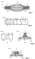
- Fig. 1 shows a schematic illustration of a sectional view through a fiber composite component 1.
- the fiber composite component 1 can in particular be a fiber-reinforced thermoplastic component.
- the term fiber composite component is used synonymously for a fiber-reinforced thermoplastic component in the following.
- the fiber composite component 1 can comprise a fiber-reinforced semi-finished product, for example an organic sheet, which comprises a fiber arrangement of one or more layers of a fiber material that are embedded in a thermoplastic matrix material, for example a plastic matrix material, or soaked by the same.
- the thermoplastic Matrix material the fiber composite component 1 is thermally deformable.
- the fiber material can comprise, for example, a fiber arrangement in the form of a woven fabric, a fiber strand, a knitted fabric, a braid, a scrim, a mat and / or a fleece.
- the scrims can be multiaxial scrims or unidirectional scrims.
- the fibers of the fiber material can be short, long and / or continuous fibers.
- the fiber composite component 1 can comprise Twintex®, for example. Reinforcing fibers, such as glass fibers, are processed into rovings with thermoplastic synthetic fibers, for example made of polypropylene, these are woven and then heated and formed into a semi-finished product under pressure.
- the fiber material of the fibers used in the fiber composite component 1 can be, for example, glass fiber, aramid fiber, carbon fiber, sisal, hemp, coconut fiber, cotton fiber and / or flax.
- the fibers can run at right angles to one another, depending on the desired mechanical properties of the fiber composite component 1 with regard to rigidity, strength and thermal expansion.
- the embodiments of the fiber composite components disclosed herein are not limited to the fiber materials mentioned and the fiber processing forms mentioned, such as woven fabric, fleece, knitted fabric or the like.
- the fiber composite component 1 can be provided in its initial form as a flat semi-finished product or as a shaped structural component.
- the fiber composite component 1 in Fig. 1 comprises at least one layer 2 of a fiber material which is impregnated by a thermoplastic matrix 3.
- the thermoplastic matrix 3 can for example thermoplastics such as acrylonitrile butadiene styrene (ABS), polyamide (PA), polyetherimide (PEI), polylactate (PLA), polymethyl methacrylate (PMMA), polycarbonate (PC), polyethylene terephthalate (PET), polyethylene (PE), Polypropylene (PP), polystyrene (PS), polyetheretherketone (PEEK), polypropylene sulfide (PPS), or polyvinylchloride (PVC).
- ABS acrylonitrile butadiene styrene
- PA polyamide
- PEI polyetherimide
- PLA polylactate
- PMMA polymethyl methacrylate
- PC polycarbonate
- PET polyethylene terephthalate
- PET polyethylene
- PE Polypropylene
- PP polysty
- the fiber composite component 1 has two areas 4 and 5 which are adjacent to one another, that is to say are either spaced apart from one another or run adjacent to one another. Areas 4 and 5 differ essentially in terms of their local degree of consolidation, that is to say the degree of compaction and solidification that the component achieves in this component zone after being subjected to pressure and heat.
- the fiber material 2 is impregnated with the matrix material 3 and compacted.
- the compression can remove air or gas inclusions from the fiber composite.
- the boundaries between the first and second areas are illustrated with B1 and B2 and dash-dotted lines. It should be clear, however, that the boundary lines between the first and second areas are not necessarily clearly sharp and that there can be intermediate areas between the first and second areas with an essentially constantly changing degree of consolidation.
- the local degree of consolidation of the fiber composite component 1 is above a first consolidation threshold value, while the local consolidation degree of the fiber composite component 1 in the second region 5 is below a second consolidation threshold value.
- the second consolidation threshold is in particular smaller than that is the first consolidation threshold value, so that one can speak of a complete or almost complete consolidation in the first area 4 and of an incomplete or partial consolidation in the second area 5.
- the second consolidation threshold value can be set to between approximately 10% and 80% of the first consolidation threshold value.
- the fiber composite component 1 of the Fig. 1 is used to form a film hinge in the second area 5.
- Film hinges or film joints are band hinges which are designed as flexible and thin-walled joint grooves between two sections of a fiber composite component to be connected.
- the proportion of matrix material in the second region 5 can be reduced in order to simplify deformation steps in the second region 5, for example kinking or bending the fiber composite component 1 in the second region 5.
- Fig. 2 shows a schematic illustration of a plan view of a fiber composite component 1 in order to explain the geometric design options for the second areas 5 by way of example.
- a fiber composite component 1 can only have one or some of the in Fig. 2 have exemplarily illustrated second areas 5.
- the number of the second areas 5 and the possible combinations of different area geometries for the second areas 5 are basically not restricted and can be selected in accordance with the desired stiffness ratios in the fiber composite component 1.
- strip-shaped second areas 5 are shown, which are interrupted by first areas 4 of a higher degree of consolidation.
- first areas 4 of a higher degree of consolidation.
- the acoustic behavior of the fiber composite component 1 due to elastic deformations can be improved.
- the vibration and damping behavior can be improved by such second regions 5.
- Meander or local areas 5 are reduced in their degree of consolidation, for example in the case of plastic deformations of the fiber composite component 1 to produce areas with increased impact strength and to be able to better absorb deformation energy in the component.
- Fig. 3 shows a schematic illustration of a plan view (A) of a fiber composite component 1 with a force introduction area 6, which lies within a second area 5 with a reduced degree of consolidation.
- the second area 4 forms a circular or elliptical area around the force introduction area 6.
- a screw dome 7 is formed on the force introduction area 6, which enables a gentler introduction of force into the fiber composite component 1 due to the reduced degree of consolidation in the second area 5.
- the screw dome 7 is better secured against overload as a result.
- Fig. 4 shows a sectional view of a fiber composite component 1 with a force introduction area 6, which lies within a second area 5 with a reduced degree of consolidation.
- the force application area 6 of the Fig. 4 is an adhesive point 8, at which an adhesive partner 8b is attached to the fiber composite component 1 via an adhesive medium 8a.
- the surface of the fiber composite component 1 is enlarged by the second region 5 with a reduced degree of consolidation, so that the adhesive medium 8a has an improved reaction surface.
- the reduced degree of consolidation in the second area 5 enables a gentler introduction of force into the fiber composite component 1 in the area of the adhesive point 8.
- Fig. 5 shows a sectional view of a fiber composite component 1 with a force introduction area 6, which lies within a second area 5 with a reduced degree of consolidation.
- the force application area 6 of the Fig. 5 is a screw connection point 9 at which a screw connection is introduced into the fiber composite component 1.
- the second area 5 with a reduced degree of consolidation the available component thickness of the fiber composite component 1 is increased locally, so that better force transmission in the area of the screw connection point 9 is possible.
- the reduced degree of consolidation in the second area 5 enables a gentler introduction of force into the fiber composite component 1 in the area of the screw connection point 9.
- rivets or welds can also be formed.
- welds there is also the advantage that in the not completely consolidated areas 5, continuous fibers can be shifted into the weld zone in a targeted manner.
- Fig. 6 shows a schematic representation of a fiber composite component 1 which has a different number of fiber layers 2 along a direction of extent. From right to left, for example, the number of layers increases in order to be able to produce local reinforcement layers. In each zone in which a new reinforcement layer begins, the rigidity of the entire fiber composite component 1 increases locally by leaps and bounds. In order to reduce the height of the jump in rigidity, a first region 4 can be formed in a zone with a first number of fiber layers 2a. This first area 4 directly adjoins a second area 5 which has a second number of fiber layers 2b that is higher than the first number of fiber layers 2a.
- the second area 5 now has a locally reduced degree of consolidation compared to the first area, the rigidity of the fiber composite component 1 increases only gradually, as a result of which the increase in rigidity over the entire fiber composite component 1 is gentler.
- the notch factor or the notch effect between the individual layer transitions is reduced.
- Fig. 7 shows a schematic illustration of a plan view of a fiber composite component 1, which in a third region 5a, for example an end section of the fiber composite component 1, has no matrix material 3, that is to say bare, unimpregnated or unwetted fibers.
- This third area 5a can adjoin a second area 5 with a reduced degree of consolidation, the second area 5 being arranged between the first area 4 and the third area 5a.
- Such third areas 5a are used, for example, at joining points of fiber composite components which are bonded to other joining partners in the area of the bare fibers.
- the fiber composite components shown can be produced, for example, by means of an injection mold of an injection molding tool for injecting thermoplastic material.
- an organic sheet or a pre-consolidated sheet for example a Twintex® sheet, or a stack of layers of such sheets can be used, which are heated as a semi-finished product or preformed component to the processing temperature of the plastic matrix and placed in the injection mold of the injection molding tool.
- the heating can also take place in the injection molding tool.
- the semi-finished product or preformed component received in the injection mold is heated to a corresponding processing temperature so that suitably heated liquid thermoplastic matrix material can also be injected into the injection mold.
- the injected matrix material can be, for example, the same material as the matrix material 3 of an organic sheet used.
- another thermoplastic material can also be injected, which can bond with the thermoplastic matrix material 3 of the semi-finished product or preformed component.
- an extrusion tool or another suitable tool can also be used.
- the invention is not limited to injection molding and extrusion.
- Fig. 8 shows a block diagram of a method M for producing a fiber composite component, for example one in one of the Figures 1 to 7 fiber composite components shown 1.
- the method M can be used in the context of an injection molding or extrusion process.
- a first area 4 of a fiber-reinforced semi-finished product for example an organic sheet or an organic sheet stack, is consolidated with at least one layer 2 of a fiber material and a thermoplastic matrix 3 which soaks the fiber material.
- This consolidation takes place up to a first degree of consolidation.
- step S2 a consolidation of a second region 5 of the fiber-reinforced semifinished product that is adjacent to the first region 4, i.e.
- the second degree of consolidation is in particular smaller than the first degree of consolidation, so that the second area 5 is not fully consolidated in relation to the first area 4, that is, it is not consolidated and compacted to the same extent as the first area 4.
- the degree of consolidation should be between 10% and 80% of the first degree of consolidation.
- steps S1 and S2 can be achieved, for example, by applying a first consolidation pressure to the fiber-reinforced semi-finished product in the first area 4, which is higher than a second consolidation pressure which is applied to the fiber-reinforced semi-finished product in the second area 5 .
- a first consolidation pressure to the fiber-reinforced semi-finished product in the first area 4
- a second consolidation pressure which is applied to the fiber-reinforced semi-finished product in the second area 5 .
- the period of time during that a consolidation pressure is exerted on the second area 5 can be reduced compared to the period of time during which a consolidation pressure is exerted on the first area 5, in order to achieve the various degrees of consolidation.
Landscapes
- Chemical & Material Sciences (AREA)
- Engineering & Computer Science (AREA)
- Composite Materials (AREA)
- Mechanical Engineering (AREA)
- Health & Medical Sciences (AREA)
- Physics & Mathematics (AREA)
- Oral & Maxillofacial Surgery (AREA)
- Thermal Sciences (AREA)
- Manufacturing & Machinery (AREA)
- Materials Engineering (AREA)
- Chemical Kinetics & Catalysis (AREA)
- Medicinal Chemistry (AREA)
- Polymers & Plastics (AREA)
- Organic Chemistry (AREA)
- Reinforced Plastic Materials (AREA)
- Casting Or Compression Moulding Of Plastics Or The Like (AREA)
- Moulding By Coating Moulds (AREA)
- Laminated Bodies (AREA)
Description
- Die Erfindung betrifft ein Faserverbundbauteil, insbesondere eine faserverstärkte Thermoplastbauteilanordnung, wie beispielsweise ein Organoblechbauteil, und ein Verfahren zum Herstellen eines derartigen Faserverbundbauteils, beispielsweise einer faserverstärkten Thermoplastbauteilanordnung.
- Eine faserverstärkte Thermoplastbauteilanordnung, wie beispielsweise eine Organoblechbauteilanordnung, besteht aus einem thermoplastischen Faser-Kunststoff-Verbund.
- Faserverstärkte Thermoplaste (FVT) sind Verbundmaterialien, welche aus Verstärkungsfasern zur Lastaufnahme und einem Matrixwerkstoff zur Gewährleistung der Faserorientierung und der Formstabilität bestehen. Als Faserwerkstoffe können dabei beispielsweise Glasfaser, Aramidfaser, Kohlenstofffaser usw., sowie Fasern auf Naturbasis, wie beispielsweise Sisal, Kokos, Hanf, Flachs usw. eingesetzt werden. Hierbei wird zwischen kurzen, langen und endlosen Verstärkungsfasern unterschieden, wobei Kurzfasern und Langfasern meist direkt mit Thermoplastgranulat verspritzt oder extrudiert werden. Endlose Verstärkungsfasern werden wiederum im Allgemeinen als Faserstränge, sogenannte Rovings, Gestricke, Gewebe oder Geflechte verarbeitet. Als Matrixwerkstoff wird ein thermoplastischer Kunststoff verwendet.
- Zur Fertigung von endlos faserverstärkten Thermoplastbauteilen in Profilform können beispielsweise die Wickeltechnik, das Pultrusionsverfahren oder die Intervall-Heißpresstechnik eingesetzt werden. Flächige Bauteile werden heute im Thermoform-Verfahren mit zusätzlichem Hinterspritzen oder Fließpressen hergestellt, beispielsweise in einem Spritzformprozess. Dazu werden in der Regel Halbzeuge verwendet, die in Form von teilweise oder vollständig vorkonsolidierten Platten angeboten und als Organobleche oder thermoplastische Prepegs bezeichnet werden. Auch textile Gebilde aus Hybridgarn, bei dem neben der Verstärkungsfaser auch die Matrix in Faserform vorliegt, können als Halbzeug eingesetzt werden.
- Die Druckschrift
WO 2012/032189 A2 offenbart ein Verfahren zur Herstellung einer Sitzlehnenrückwand für eine Sitzlehne unter Verwendung mindestens eines Organoblechs. Die DruckschriftDE 10 2012 104 044 A1 offenbart ein Verfahren zum zumindest bereichsweisen Konsolidieren eines thermoplastischen Vorformlings in einem Formwerkzeug. Die DruckschriftDE 10 2011 056 686 A1 offenbart ein Verfahren zum Herstellen eines Faserverbundbauteils. DieDE 195 31 406 A1 offenbart ein Halbzeug für Preßformteile. DieEP 1 603 735 A1 beschreibt ein Verfahren zur Herstellung einer Verbindung zwischen Verbundteilen. - Es besteht ein Bedarf nach Lösungen für die Bereitstellung von Faserverbundbauteilen, die eine verbesserte lokale Kraftaufnahme ermöglichen sowie verbesserte Steifigkeits- und Festigkeitseigenschaften aufweisen.
- Demgemäß wird ein Faserverbundbauteil mit den Merkmalen des Patentanspruchs 1 und ein Verfahren zum Herstellen eines Faserverbundbauteils mit den Merkmalen des Patentanspruches 6 vorgeschlagen.
- Gemäß einem ersten Aspekt der Erfindung umfasst ein Faserverbundbauteil mindestens eine Lage eines Fasermaterials, und eine thermoplastischen Matrix, welche das Fasermaterial tränkt, wobei das Faserverbundbauteil mindestens einen ersten Bereich aufweist, in dem der lokale Konsolidierungsgrad des Faserverbundbauteils über einem ersten Konsolidierungsschwellwert liegt, und wobei das Faserverbundbauteil mindestens einen zweiten, zu dem ersten Bereich benachbart liegenden Bereich aufweist, in dem der lokale Konsolidierungsgrad des Faserverbundbauteils unter einem zweiten Konsolidierungsschwellwert liegt, wobei der zweite Konsolidierungsschwellwert kleiner als der erste Konsolidierungsschwellwert ist.
- Erfindungsgemäß bildet der zweite Bereich ein Filmscharnier aus. Dies bietet den Vorteil, dass in Bereichen des Faserverbundbauteils, die nachfolgenden Umformschritten unterworfen werden sollen, derartige Umformschritte durch den verringerten Konsolidierungsgrad vereinfacht werden.
- Erfindungsgemäß umfasst das Faserverbundbauteil mindestens ein Organoblech oder ein vorkonsolidiertes Blech, beispielsweise ein Twintex®-Blech. Derartige Bleche haben den Vorteil, dass die Verstärkungsfasern bereits teilweise imprägniert und konsolidiert sind und darum nur noch eine kurze Verarbeitungszeit und ein relativ geringer Druck zum Umformen erforderlich sind. Darüber hinaus ist es für die vorkonsolidierten Bereiche nicht mehr zwangsläufig notwendig, im Rahmen der Weiterverarbeitung der Organobleche eine weitere Konsolidierung vorzunehmen, da diese vorkonsolidierten Bereiche schon einen ausreichenden Teilkonsolidierungsgrad, das heißt eine nicht vollständige Konsolidierung im gewünschten Maße aufweisen.
- Gemäß einem zweiten Aspekt der Erfindung weist ein Verfahren zum Herstellen eines Faserverbundbauteils ein Konsolidieren eines ersten Bereichs eines faserverstärkten Halbzeugs mit mindestens einer Lage eines Fasermaterials und einer thermoplastischen Matrix, welche das Fasermaterial tränkt, bis zu einem ersten Konsolidierungsgrad, und ein Konsolidieren eines zu dem ersten Bereich benachbart liegenden zweiten Bereichs des faserverstärkten Halbzeugs bis zu einem von dem ersten Konsolidierungsgrad verschiedenen zweiten Konsolidierungsgrad auf, wobei der zweite Konsolidierungsgrad kleiner als der erste Konsolidierungsgrad ist, und wobei der zweite Bereich ein Filmscharnier ausbildet, und/oder wobei das Faserverbundbauteil (1) mindestens ein Organoblech oder ein vorkonsolidiertes Blech umfasst.
- Eine wesentliche Idee der Erfindung besteht darin, Steifigkeitsunterschiede zwischen verschiedenen Abschnitten eines Faserverbundbauteils nicht oder nicht nur über eine einzubringende Bauteilgeometrie oder die Wahl des Fasermaterials zu beeinflussen, sondern eine gezielte örtliche Variation des Konsolidierungsgrades bzw. des Kompaktierungsgrades des Faserverbundbauteils in bestimmten Abschnitten vorzunehmen. Durch eine Einstellung des Konsolidierungsgrades, beispielsweise über die Einstellung unterschiedlicher Kompaktierungsdrücke oder Kompaktierungstemperaturen bei der Verfestigung und/oder Imprägnierung des Fasermaterials mit einer thermoplastischen Matrix, kann die lokale Steifigkeit sowie die lokale Schlagzähigkeit des Faserverbundbauteils eingestellt werden.
- Vorteilhafte technische Effekte dieser Vorgehensweise sind die Möglichkeiten zur Ausbildung von Zonen lokal verminderter Schlagzähigkeit, zur Verbesserung des Beulverhaltens, zur Ausbildung von Zonen erhöhter Aufnahmefähigkeit von Verformungsenergie und/oder zur Verbesserung der lokalen Krafteinleitung.
- Vorteilhafte Ausgestaltungen und Weiterbildungen ergeben sich aus den weiteren Unteransprüchen sowie aus der Beschreibung unter Bezugnahme auf die Figuren der Zeichnung.
- Gemäß einer Ausführungsform des erfindungsgemäßen Faserverbundbauteils kann der zweite Konsolidierungsschwellwert zwischen 10% und 80% des ersten Konsolidierungsschwellwerts betragen. Durch die gezielte Einstellung verschiedener Konsolidierungsgrade können das akustische Verhalten, das Schwingungs-Dämpfungsverhalten sowie die Schlagzähigkeit des Faserverbundbauteils günstig beeinflusst werden.
- Gemäß einer weiteren Ausführungsform des erfindungsgemäßen Faserverbundbauteils kann das Faserverbundbauteil weiterhin einen Krafteinleitungsbereich aufweisen, wobei der zweite Bereich einen kreisförmigen oder elliptischen Bereich um den Krafteinleitungsbereich ausbildet.
- Gemäß einer weiteren Ausführungsform des erfindungsgemäßen Faserverbundbauteils kann der Krafteinleitungsbereich eine Klebestelle, eine Nietstelle, eine Schweißstelle, eine Verschraubungsstelle oder einen Schraubdom ausbilden. Gerade in den Bereichen derartiger Krafteinleitungsstellen ist eine gleichmäßigere und effizientere Krafteinleitung in das Faserverbundbauteil in vorteilhafter Weise möglich.
- Gemäß einer weiteren Ausführungsform des erfindungsgemäßen Faserverbundbauteils kann der erste Bereich eine erste Anzahl von Faserlagen aufweisen, und der zweite Bereich kann eine zweite Anzahl von Faserlagen aufweisen, die höher als die erste Anzahl von Faserlagen ist. Steifigkeitssprünge, die durch das Einbringen lokaler Verstärkungsfaserlagen entstehen, können auf diese Weise durch das gezielte Ausbilden von Übergangsbereichen nicht vollständiger Konsolidierung besonders vorteilhaft abgemildert werden
- Gemäß einer weiteren Ausführungsform des erfindungsgemäßen Faserverbundbauteils kann das Faserverbundbauteil weiterhin einen dritten Bereich aufweisen, welcher Lagen mit von der thermoplastischen Matrix ungetränktem Fasermaterial aufweist, wobei der zweite Bereich zwischen dem ersten Bereich und dem dritten Bereich angeordnet ist. Besonders bei Multimaterialverbindungen, bei denen ein Faserverbundbauteil an den jeweiligen Fügestellen in einen Bereich blanker bzw. ungetränkter Fasern ausläuft, kann ein Übergangsbereich zwischen dem vollständig konsolidierten, mit Matrixmaterial getränkten Bereich und dem Bereich ungetränkter Fasern ausgebildet werden, der die Krafteinleitung in die Fasern in vorteilhafter Weise verbessern kann.
- Gemäß einer weiteren Ausführungsform des erfindungsgemäßen Faserverbundbauteils kann das Fasermaterial aus einer Faseranordnung aus Glasfasern, Aramidfasern, Kohlenstofffasern, Sisal, Hanf, Kokosfasern, Baumwollfasern und/oder Flachs gebildet sein, und die Faseranordnung kann ein Gewebe, einen Faserstrang, ein Gestrick, ein Geflecht, ein Gelege, eine Matte und/oder ein Vlies bilden. Neben den explizit angeführten Fasern auf Naturbasis können ebenso weitere Fasern auf Naturbasis eingesetzt werden. Bei den Fasern können dabei kurze, lange und/oder Endlosfasern eingesetzt werden.
- Gemäß einer weiteren Ausführungsform des erfindungsgemäßen Verfahrens kann der zweite Konsolidierungsgrad zwischen 10% und 80% des ersten Konsolidierungsgrads betragen.
- Gemäß einer weiteren Ausführungsform des erfindungsgemäßen Verfahrens kann das Konsolidieren des ersten Bereichs ein Aufbringen eines ersten Konsolidierungsdrucks auf das faserverstärkte Halbzeug, und das Konsolidieren des zweiten Bereichs ein Aufbringen eines zweiten Konsolidierungsdrucks, welcher geringer als der erste Konsolidierungsdruck ist, auf das faserverstärkte Halbzeug umfassen.
- Die obigen Ausgestaltungen und Weiterbildungen lassen sich, sofern sinnvoll, beliebig miteinander kombinieren. Weitere mögliche Ausgestaltungen, Weiterbildungen und Implementierungen der Erfindung umfassen auch nicht explizit genannte Kombinationen von zuvor oder im Folgenden bezüglich der Ausführungsbeispiele beschriebenen Merkmale der Erfindung. Insbesondere wird dabei der Fachmann auch Einzelaspekte als Verbesserungen oder Ergänzungen zu der jeweiligen Grundform der vorliegenden Erfindung hinzufügen.
- Die vorliegende Erfindung wird nachfolgend anhand der in den schematischen Figuren der Zeichnungen angegebenen Ausführungsbeispiele näher erläutert. Es zeigen dabei:
- Fig. 1
- eine schematische Illustration einer Schnittansicht eines Faserverbundbauteils gemäß einer Ausführungsform der Erfindung;
- Fig. 2
- eine schematische Illustration von Aufsichten auf ein Faserverbundbauteil gemäß weiterer Ausführungsformen der Erfindung;
- Fig. 3
- eine schematische Illustration einer Schnittansicht und einer Draufsicht auf ein Faserverbundbauteil gemäß einer weiteren Ausführungsform der Erfindung;
- Fig. 4
- eine schematische Illustration einer Schnittansicht eines Faserverbundbauteils gemäß einer weiteren Ausführungsform der Erfindung;
- Fig. 5
- eine schematische Illustration einer Schnittansicht eines Faserverbundbauteils gemäß einer weiteren Ausführungsform der Erfindung;
- Fig. 6
- eine schematische Illustration einer Schnittansicht eines Faserverbundbauteils gemäß einer weiteren Ausführungsform der Erfindung;
- Fig. 7
- eine schematische Illustration einer Schnittansicht eines Faserverbundbauteils gemäß einer weiteren Ausführungsform der Erfindung; und
- Fig. 8
- ein Blockschaubild eines Verfahrensablaufs zum Herstellen eines Faserverbundbauteils gemäß einer weiteren Ausführungsform der Erfindung.
- Die beiliegenden Zeichnungen sollen ein weiteres Verständnis der Ausführungsformen der Erfindung vermitteln. Sie veranschaulichen Ausführungsformen und dienen im Zusammenhang mit der Beschreibung der Erklärung von Prinzipien und Konzepten der Erfindung. Andere Ausführungsformen und viele der genannten Vorteile ergeben sich im Hinblick auf die Zeichnungen. Die Elemente in den Zeichnungen sind nicht notwendigerweise maßstabsgetreu zueinander gezeigt.
- In den Figuren sind gleiche, funktionsgleiche und gleich wirkende Elemente, Merkmale und Komponenten - sofern nichts gegenteiliges explizit ausgeführt ist - jeweils mit denselben Bezugszeichen versehen.
-
Fig. 1 zeigt eine schematische Illustration einer Schnittansicht durch ein Faserverbundbauteil 1. Das Faserverbundbauteil 1 kann dabei insbesondere ein faserverstärktes Thermoplastbauteil sein. Aus Gründen der Einfachheit wird im Folgen der Begriff Faserverbundbauteil synonym für ein faserverstärktes Thermoplastbauteil verwendet. Das Faserverbundbauteil 1 kann dabei ein faserverstärktes Halbzeug umfassen, beispielsweise ein Organoblech, welches eine Faseranordnung aus ein oder mehr Lagen eines Fasermaterials umfasst, die in ein thermoplastisches Matrixmaterial, beispielsweise ein Kunststoffmatrixmaterial, eingebettet bzw. durch selbiges getränkt sind. Durch die Verwendung des thermoplastischen Matrixmaterials ist das Faserverbundbauteil 1 thermisch umformbar. - Das Fasermaterial kann beispielsweise eine Faseranordnung in Form eines Gewebes, eines Faserstrangs, eines Gestrickes, eines Geflechts, eines Geleges, einer Matte und/oder eines Vlies umfassen. Die Gelege können dabei Multiaxialgelege oder unidirektionale Gelege sein. Des Weiteren können die Fasern des Fasermaterials kurze, lange und/oder Endlosfasern sein. Das Faserverbundbauteil 1 kann beispielsweise Twintex® umfassen. Dabei werden Verstärkungsfasern, wie beispielsweise Glasfasern, mit thermoplastischen Kunststofffasern, zum Beispiel aus Polypropylen zu Rovings verarbeitet, diese verwoben und anschließend erwärmt und unter Druck zu einem Halbzeug geformt.
- Der Faserwerkstoff der in dem Faserverbundbauteil 1 verwendeten Fasern kann beispielsweise Glasfaser, Aramidfaser, Kohlenstofffaser, Sisal, Hanf, Kokosfaser, Baumwollfaser und/oder Flachs sein. Die Fasern können dabei rechtwinklig zueinander verlaufen, je nach gewünschten mechanischen Eigenschaften des Faserverbundbauteils 1 hinsichtlich Steifigkeit, Festigkeit und Wärmeausdehnung. Die Ausführungsformen der hierin offenbarten Faserverbundbauteile sind auf die genannten Faserwerkstoffe und die genannten Faserverarbeitungsformen, wie Gewebe, Vlies, Gestrick oder ähnliches nicht beschränkt. Das Faserverbundbauteil 1 kann dabei in seiner Ausgangsform als flächiges Halbzeug oder als geformtes Strukturbauteil bereitgestellt werden.
- Das Faserverbundbauteil 1 in
Fig. 1 umfasst mindestens eine Lage 2 eines Fasermaterials, die durch eine thermoplastische Matrix 3 getränkt ist. Die thermoplastische Matrix 3 kann beispielsweise thermoplastische Kunststoffe, wie etwa Acrylnitril-Butadien-Styrol (ABS), Polyamid (PA), Polyetherimid (PEI), Polylactat (PLA), Polymethylmethacrylat (PMMA), Polycarbonat (PC), Polyethylenterephthalat (PET), Polyethylen (PE), Polypropylen (PP), Polystyrol (PS), Polyetheretherketon (PEEK), Polypropylensulfid (PPS) oder Polyvinylchlorid (PVC) umfassen. - Das Faserverbundbauteil 1 besitzt zwei Bereiche 4 und 5, die benachbart zueinander liegen, das heißt entweder beabstandet zueinander sind oder angrenzend zueinander verlaufen. Die Bereiche 4 und 5 unterscheiden sich im Wesentlichen über ihren lokalen Konsolidierungsgrad, das heißt dem Kompaktierungs- und Verfestigungsgrad, den das Bauteil in dieser Bauteilzone nach einer Beaufschlagung mit Druck und Wärme erreicht. Durch die Konsolidierung wird das Fasermaterial 2 mit dem Matrixmaterial 3 imprägniert und verdichtet. Durch die Verdichtung können Luft- oder Gaseinschlüsse aus dem Faserverbund entfernt werden. Im Folgenden werden jeweils die Grenzen zwischen ersten und zweiten Bereichen mit B1 und B2 sowie strichpunktierten Linien veranschaulicht. Es sollte dabei jedoch klar sein, dass die Grenzverläufe zwischen ersten und zweiten Bereichen nicht zwangsläufig eindeutig scharf sind und zwischen ersten und zweiten Bereiche jeweils Zwischenbereiche mit sich im Wesentlichen stetig änderndem Konsolidierungsgrad liegen können.
- In dem ersten Bereich 4 liegt der lokale Konsolidierungsgrad des Faserverbundbauteils 1 über einem ersten Konsolidierungsschwellwert, während der lokale Konsolidierungsgrad des Faserverbundbauteils 1 in dem zweiten Bereich 5 unter einem zweiten Konsolidierungsschwellwert liegt. Der zweite Konsolidierungsschwellwert ist dabei insbesondere kleiner als der erste Konsolidierungsschwellwert ist, so dass man in dem ersten Bereich 4 von einer vollständigen oder nahezu vollständigen und in dem zweiten Bereich 5 von einer unvollständigen oder teilweisen Konsolidierung sprechen kann. Beispielsweise kann der zweite Konsolidierungsschwellwert auf etwa zwischen 10% und 80% des ersten Konsolidierungsschwellwerts eingestellt werden. Dadurch kann die Haftung zwischen dem Fasermaterial und dem Matrixmaterial selektiv eingestellt werden.
- Das Faserverbundbauteil 1 der
Fig. 1 wird eingesetzt, um ein Filmscharnier in dem zweiten Bereich 5 auszubilden. Filmscharniere bzw. Filmgelenke sind Bandscharniere, welche als flexible und dünnwandige Gelenkrille zwischen zwei zu verbindenden Abschnitten eines Faserverbundbauteils ausgebildet sind. Zudem kann der Anteil an Matrixmaterial in dem zweiten Bereich 5 verringert werden, um Umformschritte in dem zweiten Bereich 5 zu vereinfachen, beispielsweise ein Knicken oder Biegen des Faserverbundbauteils 1 in dem zweiten Bereich 5. -
Fig. 2 zeigt eine schematische Illustration einer Aufsicht auf ein Faserverbundbauteil 1, um die geometrischen Gestaltungsmöglichkeiten für die zweiten Bereiche 5 exemplarisch zu erläutern. Ein Faserverbundbauteil 1 kann dabei nur einen oder einige der inFig. 2 beispielhaft dargestellten zweiten Bereiche 5 aufweisen. Die Anzahl der zweiten Bereiche 5 sowie die Kombinationsmöglichkeiten unterschiedlicher Bereichsgeometrien für die zweiten Bereiche 5 sind dabei grundsätzlich nicht eingeschränkt und können entsprechend der gewünschten Steifigkeitsverhältnisse in dem Faserverbundbauteil 1 gewählt werden. - Ganz links in
Fig. 2 sind streifenförmige zweite Bereiche 5 gezeigt, die durch erste Bereiche 4 höheren Konsolidierungsgrads unterbrochen sind. Dadurch kann beispielsweise das akustische Verhalten des Faserverbundbauteils 1 aufgrund elastischer Verformungen verbessert werden. Zudem kann das Schwingungs- und Dämpfungsverhalten durch derartige zweite Bereiche 5 verbessert werden. - In der Mitte und rechts in
Fig. 2 sind mäandrierte oder lokale Bereiche 5 in ihrem Konsolidierungsgrad vermindert, um beispielsweise bei plastischen Verformungen des Faserverbundbauteils 1 Bereiche mit erhöhter Schlagzähigkeit zu erzeugen und Verformungsenergie besser im Bauteil aufnehmen zu können. - Besonders gut eignen sich die zweiten Bereiche 5 verminderter oder nicht vollständiger Konsolidierung für den Einsatz in Krafteinleitungsbereichen von Faserverbundbauteilen, von denen in den
Fig. 3, 4 und5 drei Beispiele dargestellt sind.Fig. 3 zeigt eine schematische Illustration einer Aufsicht (A) eines Faserverbundbauteils 1 mit einem Krafteinleitungsbereich 6, der innerhalb eines zweiten Bereichs 5 verminderten Konsolidierungsgrads liegt. Der zweite Bereich 4 bildet hierbei einen kreisförmigen oder elliptischen Bereich um den Krafteinleitungsbereich 6 aus. Wie sich in der Schnittansicht (B) des Faserverbundbauteils 1 der Ansicht (A) darstellt, ist auf dem Krafteinleitungsbereich 6 ein Schraubdom 7 ausgebildet, der durch den verminderten Konsolidierungsgrad im zweiten Bereich 5 eine sanftere Krafteinleitung in das Faserverbundbauteil 1 ermöglicht. Zudem ist der Schraubdom 7 dadurch besser gegen Überlast gesichert. -
Fig. 4 zeigt eine Schnittansicht eines Faserverbundbauteils 1 mit einem Krafteinleitungsbereich 6, der innerhalb eines zweiten Bereichs 5 verminderten Konsolidierungsgrads liegt. Der Krafteinleitungsbereich 6 derFig. 4 ist eine Klebestelle 8, an der über ein Klebemedium 8a ein Klebepartner 8b an das Faserverbundbauteil 1 angefügt wird. Durch den zweiten Bereich 5 verminderten Konsolidierungsgrads wird die Oberfläche des Faserverbundbauteils 1 vergrößert, so dass das Klebemedium 8a eine verbesserte Reaktionsfläche erhält. Zudem wird durch den verminderten Konsolidierungsgrad im zweiten Bereich 5 eine sanftere Krafteinleitung in das Faserverbundbauteil 1 im Bereich der Klebestelle 8 ermöglicht. -
Fig. 5 zeigt eine Schnittansicht eines Faserverbundbauteils 1 mit einem Krafteinleitungsbereich 6, der innerhalb eines zweiten Bereichs 5 verminderten Konsolidierungsgrads liegt. Der Krafteinleitungsbereich 6 derFig. 5 ist eine Verschraubungsstelle 9, an der eine Verschraubung in das Faserverbundbauteil 1 eingebracht wird. Durch den zweiten Bereich 5 verminderten Konsolidierungsgrads wird die zur Verfügung stehende Bauteildicke des Faserverbundbauteils 1 lokal erhöht, so dass eine bessere Kraftübertragung im Bereich der Verschraubungsstelle 9 möglich ist. Zudem wird durch den verminderten Konsolidierungsgrad im zweiten Bereich 5 eine sanftere Krafteinleitung in das Faserverbundbauteil 1 im Bereich der Verschraubungsstelle 9 ermöglicht. - In ähnlicher Weise wie in
Fig. 4 und5 können auch Nietstellen oder Schweißstellen ausgebildet werden. Bei Schweißstellen ergibt sich zudem der Vorteil, dass in den nicht vollständig konsolidierten Bereichen 5 gezielt Endlosfasern in die Schweißzone verschoben werden können. -
Fig. 6 zeigt eine schematische Darstellung eines Faserverbundbauteils 1, welches entlang einer Erstreckungsrichtung verschiedene Anzahl von Faserlagen 2 aufweist. Von rechts nach links nimmt dabei beispielsweise die Lagenanzahl zu, um lokale Verstärkungslagen erzeugen zu können. In jeder Zone, in der eine neue Verstärkungslage beginnt, nimmt die Steifigkeit des gesamten Faserverbundbauteils 1 lokal sprunghaft zu. Um die Höhe des Steifigkeitssprungs zu vermindern, kann ein erster Bereich 4 in einer Zone mit einer ersten Anzahl von Faserlagen 2a ausgebildet werden. Dieser erste Bereich 4 schließt sich unmittelbar an einen zweiten Bereich 5 an, der eine zweite Anzahl von Faserlagen 2b aufweist, die höher als die erste Anzahl von Faserlagen 2a ist. Wenn der zweite Bereich 5 nun gegenüber dem ersten Bereich einen lokal verringerten Konsolidierungsgrad aufweist, nimmt die Steifigkeit des Faserverbundbauteils 1 nur schrittweise zu, wodurch der Steifigkeitsanstieg über das gesamte Faserverbundbauteil 1 hinweg sanfter verläuft. Zudem wird der Kerbfaktor bzw. die Kerbwirkung zwischen den einzelnen Lagenübergängen verringert. -
Fig. 7 zeigt eine schematische Illustration einer Aufsicht auf ein Faserverbundbauteil 1, welches in einem dritten Bereich 5a, beispielsweise ein Endabschnitt des Faserverbundbauteils 1, kein Matrixmaterial 3, das heißt blanke, ungetränkte oder unbenetzte Fasern aufweist. Dieser dritte Bereich 5a kann sich an einen zweiten Bereich 5 verminderten Konsolidierungsgrades anschließen, wobei der zweite Bereich 5 zwischen dem ersten Bereich 4 und dem dritten Bereich 5a angeordnet ist. Solche dritten Bereiche 5a werden beispielsweise an Fügestellen von Faserverbundbauteilen eingesetzt, die durch Kleben mit anderen Fügepartnern im Bereich der blanken Fasern verbunden werden. Durch die stufenweise Verringerung des Konsolidierungsgrades vom ersten Bereich 4 über den zweiten Bereich 5 zum dritten Bereich 5a hin kann eine optimale Krafteinleitung in die Fasern gewährleistet werden. - Die in den
Fig. 1 bis 7 gezeigten Faserverbundbauteile können beispielsweise mittels einer Spritzgussform eines Spritzgusswerkzeugs zum Einspritzen thermoplastischen Kunststoffs hergestellt werden. Dabei kann zum Beispiel ein Organoblech oder ein vorkonsolidiertes Blech, beispielsweise ein Twintex®-Blech, bzw. Lagenstapel aus derartigen Blechen eingesetzt werden, die als Halbzeug oder vorgeformtes Bauteil auf die Verarbeitungstemperatur der Kunststoffmatrix aufgeheizt und in die Spritzgussform des Spritzgusswerkzeugs eingelegt werden. Bei dünnwandigen Faserverbundbauteilen kann die Aufheizung auch im Spritzgusswerkzeug erfolgen. - Das in der Spritzgussform aufgenommene Halbzeug oder vorgeformte Bauteil wird auf eine entsprechende Verarbeitungstemperatur erwärmt, so dass ebenfalls geeignet erwärmtes flüssiges thermoplastisches Matrixmaterial in die Spritzgussform eingespritzt werden kann. Das eingespritzte Matrixmaterial kann dabei beispielsweise das gleiche Material wie das Matrixmaterial 3 eines verwendeten Organoblechs sein. Alternativ kann auch ein anderer thermoplastischer Kunststoff eingespritzt werden, welcher sich mit dem thermoplastischen Matrixmaterial 3 des Halbzeugs oder vorgeformten Bauteils verbinden kann.
- Statt eines Spritzgusswerkzeugs kann auch ein Fließpresswerkzeug oder ein anderes geeignetes Werkzeug eingesetzt werden. Die Erfindung ist jedoch auf Spritzgießen und Fließpressen nicht beschränkt.
-
Fig. 8 zeigt ein Blockdiagramm eines Verfahrens M zum Herstellen eines Faserverbundbauteils, beispielsweise eines in einer derFig. 1 bis 7 gezeigten Faserverbundbauteile 1. Das Verfahren M kann dabei im Rahmen eines Spritzgieß- oder Fließpressprozesses eingesetzt werden. In einem ersten Schritt S1 erfolgt ein Konsolidieren eines ersten Bereichs 4 eines faserverstärkten Halbzeugs, beispielsweise eines Organoblechs oder eines Organblechstapels, mit mindestens einer Lage 2 eines Fasermaterials und einer thermoplastischen Matrix 3, welche das Fasermaterial tränkt. Dieses Konsolidieren erfolgt bis zu einem ersten Konsolidierungsgrad. Gleichzeitig oder nacheinander erfolgt in Schritt S2 ein Konsolidieren eines zu dem ersten Bereich 4 benachbart liegenden, das heißt eines beabstandeten bzw. an den ersten Bereich 4 angrenzenden, zweiten Bereichs 5 des faserverstärkten Halbzeugs bis zu einem von dem ersten Konsolidierungsgrad verschiedenen zweiten Konsolidierungsgrad. Der zweite Konsolidierungsgrad ist dabei insbesondere kleiner als der erste Konsolidierungsgrad, so dass der zweite Bereich 5 bezogen auf den ersten Bereich 4 nicht vollständig konsolidiert wird, das heißt nicht im selben Umfang verfestigt und kompaktiert wird wie der erste Bereich 4. Zum Beispiel kann der zweite Konsolidierungsgrad zwischen 10% und 80% des ersten Konsolidierungsgrads betragen. - Das verschieden ausgeprägte Konsolidieren in den Schritten S1 und S2 kann beispielsweise dadurch erreicht werden, dass auf den ersten Bereich 4 ein erster Konsolidierungsdruck auf das faserverstärkte Halbzeug aufgebracht, der höher als ein zweiter Konsolidierungsdruck ist, der im zweiten Bereich 5 auf das faserverstärkte Halbzeug aufgebracht wird. Alternativ oder zusätzlich dazu kann auch die Zeitdauer, während der ein Konsolidierungsdruck auf den zweiten Bereich 5 ausgeübt wird, gegenüber der Zeitdauer, während der ein Konsolidierungsdruck auf den ersten Bereich 5 ausgeübt wird, vermindert werden, um die verschiedenen Konsolidierungsgrade zu erreichen. Schließlich ist es auch möglich, den Anteil des Matrixmaterials im zweiten Bereich 5 gegenüber dem des ersten Bereichs 4 zu verringern, um den geringeren Konsolidierungsgrad im zweiten Bereich 5 zu ermöglichen.
- Obwohl die vorliegende Erfindung anhand bevorzugter Ausführungsbeispiele vorstehend vollständig beschrieben wurde, ist sie darauf nicht beschränkt, sondern auf vielfältige Art und Weise modifizierbar. Insbesondere sind einzelne Merkmale zuvor separat beschriebener Ausführungsformen auch untereinander kombinierbar, sofern nichts gegenteiliges explizit angegeben ist.
-
- 1
- Faserverbundbauteil
- 2
- Faserlage
- 2a
- Faserlagen
- 2b
- Faserlagen
- 3
- Thermoplastische Matrix
- 4
- Erster Bereich
- 5
- Zweiter Bereich
- 5a
- Dritter Bereich
- 6
- Krafteinleitungsbereich
- 7
- Schraubdom
- 8
- Klebestelle
- 8a
- Klebemedium
- 8b
- Klebepartner
- 9
- Verschraubungsstelle
- B1
- Bereichsgrenze
- B2
- Bereichsgrenze
- M
- Verfahren
- S1
- Verfahrensschritt
- S2
- Verfahrensschritt
Claims (7)
- Faserverbundbauteil (1), mit:mindestens einer Lage (2) eines Fasermaterials; undeiner thermoplastischen Matrix (3), welche das Fasermaterial tränkt,wobei das Faserverbundbauteil (1) mindestens einen ersten Bereich (4) aufweist, der eine erste Anzahl von Faserlagen (2a) aufweist, und in dem der lokale Konsolidierungsgrad des Faserverbundbauteils (1) über einem ersten Konsolidierungsschwellwert liegt, undwobei das Faserverbundbauteil (1) mindestens einen zweiten, zu dem ersten Bereich (4) benachbart liegenden Bereich (5) aufweist, der eine zweite Anzahl von Faserlagen (2b) aufweist, die höher als die erste Anzahl von Faserlagen (2a) ist, und in dem der lokale Konsolidierungsgrad des Faserverbundbauteils (1) unter einem zweiten Konsolidierungsschwellwert liegt,wobei der zweite Konsolidierungsschwellwert kleiner als der erste Konsolidierungsschwellwert ist, und wobei der zweite Bereich (5) ein Filmscharnier ausbildet und/oder wobei das Faserverbundbauteil (1) mindestens ein Organoblech oder ein vorkonsolidiertes Blech umfasst.
- Faserverbundbauteil (1) nach Anspruch 1, wobei der zweite Konsolidierungsschwellwert zwischen 10% und 80% des ersten Konsolidierungsschwellwerts beträgt.
- Faserverbundbauteil (1) nach einem der Ansprüche 1 und 2, weiterhin mit einem dritten Bereich (5a), welcher Lagen (2) mit von der thermoplastischen Matrix (3) ungetränktem Fasermaterial aufweist,
wobei der zweite Bereich (5) zwischen dem ersten Bereich (4) und dem dritten Bereich (5a) angeordnet ist. - Faserverbundbauteil (1) nach einem der Ansprüche 1 bis 3, wobei das Fasermaterial aus einer Faseranordnung aus Glasfasern, Aramidfasern, Kohlenstofffasern, Sisal, Hanf, Kokosfasern, Baumwollfasern und/oder Flachs gebildet ist, und wobei die Faseranordnung ein Gewebe, einen Faserstrang, ein Gestrick, ein Geflecht, ein Gelege, eine Matte und/oder ein Vlies bildet.
- Faserverbundbauteil (1) nach einem der Ansprüche 1 bis 4, wobei das Faserverbundbauteil (1) ein endlosfaserverstärktes Faserverbundbauteil (1) ist.
- Verfahren (M) zum Herstellen eines Faserverbundbauteils (1), umfassend:
Konsolidieren (S1) eines ersten Bereichs (4) eines faserverstärkten Halbzeugs mit einer ersten Anzahl von Faserlagen und einer thermoplastischen Matrix (3), welche das Fasermaterial tränkt, bis zu einem ersten Konsolidierungsgrad; und Konsolidieren (S2) eines zu dem ersten Bereich (4) benachbart liegenden zweiten Bereichs (5) des faserverstärkten Halbzeugs bis zu einem von dem ersten Konsolidierungsgrad verschiedenen zweiten Konsolidierungsgrad, wobei der zweite Bereich (5) eine zweite Anzahl von Faserlagen (2b) aufweist, die höher als die erste Anzahl von Faserlagen (2a) ist, und wobei der zweite Konsolidierungsgrad kleiner als der erste Konsolidierungsgrad ist, und wobei der zweite Bereich (5) ein Filmscharnier ausbildet und/oder wobei das Faserverbundbauteil (1) mindestens ein Organoblech oder ein vorkonsolidiertes Blech umfasst. - Verfahren (M) nach Anspruch 6, wobei der zweite Konsolidierungsgrad zwischen 10% und 80% des ersten Konsolidierungsgrads beträgt.
Priority Applications (1)
| Application Number | Priority Date | Filing Date | Title |
|---|---|---|---|
| PL15712113T PL3122543T3 (pl) | 2014-03-28 | 2015-03-23 | Element konstrukcyjny z kompozytu włóknistego i sposób wytwarzania elementu konstrukcyjnego z kompozytu włóknistego |
Applications Claiming Priority (2)
| Application Number | Priority Date | Filing Date | Title |
|---|---|---|---|
| DE102014205861.9A DE102014205861A1 (de) | 2014-03-28 | 2014-03-28 | Faserverbundbauteil und Verfahren zum Herstellen eines Faserverbundbauteils |
| PCT/EP2015/056045 WO2015144612A2 (de) | 2014-03-28 | 2015-03-23 | Faserverbundbauteil und verfahren zum herstellen eines faserverbundbauteils |
Publications (2)
| Publication Number | Publication Date |
|---|---|
| EP3122543A2 EP3122543A2 (de) | 2017-02-01 |
| EP3122543B1 true EP3122543B1 (de) | 2021-06-23 |
Family
ID=52737095
Family Applications (1)
| Application Number | Title | Priority Date | Filing Date |
|---|---|---|---|
| EP15712113.8A Active EP3122543B1 (de) | 2014-03-28 | 2015-03-23 | Faserverbundbauteil und verfahren zum herstellen eines faserverbundbauteils |
Country Status (7)
| Country | Link |
|---|---|
| US (1) | US20170174850A1 (de) |
| EP (1) | EP3122543B1 (de) |
| KR (2) | KR101995848B1 (de) |
| CN (1) | CN106573420B (de) |
| DE (1) | DE102014205861A1 (de) |
| PL (1) | PL3122543T3 (de) |
| WO (1) | WO2015144612A2 (de) |
Families Citing this family (2)
| Publication number | Priority date | Publication date | Assignee | Title |
|---|---|---|---|---|
| DE102021107363A1 (de) | 2021-03-24 | 2022-09-29 | Delcotex Delius Techtex Gmbh & Co. Kg | Textiles Flächengebilde und dessen Verwendung sowie Verfahren zu dessen Herstellung |
| US11766840B2 (en) * | 2021-08-30 | 2023-09-26 | The Boeing Company | Apparatus and method to enable in-plane bending of high contour composite structures in post-forming operations |
Family Cites Families (16)
| Publication number | Priority date | Publication date | Assignee | Title |
|---|---|---|---|---|
| JPS6224039A (ja) * | 1985-07-24 | 1987-02-02 | Nhk Spring Co Ltd | 繊維強化樹脂製板ばね |
| GB8527023D0 (en) * | 1985-11-01 | 1985-12-04 | Wiggins Teape Group Ltd | Moulded fibre reinforced plastic articles |
| DE19531406A1 (de) * | 1995-08-26 | 1997-02-27 | Borgers Johann Gmbh Co Kg | Halbzeug für Preßformteile |
| FR2768076B1 (fr) * | 1997-09-10 | 2000-08-04 | Peguform France | Procede de realisation d'une zone rigidifiee formant insert dans un panneau composite du type sandwich, et panneau comprenant une telle zone |
| JP2002240566A (ja) * | 2001-02-21 | 2002-08-28 | Nissan Motor Co Ltd | 車輌用樹脂パネル及び車輌用樹脂パネルの製造方法 |
| GB0108331D0 (en) * | 2001-04-03 | 2001-05-23 | Structural Polymer Systems Ltd | Bonding material |
| DE10356185A1 (de) * | 2002-12-10 | 2004-06-24 | Sumitomo Chemical Co., Ltd. | Faser/Harz-Komposit und daraus hergestellter Formkörper |
| CN100393504C (zh) * | 2003-03-06 | 2008-06-11 | 维斯塔斯风力系统公司 | 具有非兼容特征的复合材料之间的连接以及制备方法 |
| DE102010013713A1 (de) * | 2010-04-02 | 2011-10-06 | Airbus Operations Gmbh | Verfahren und Vorrichtung zur Herstellung eines faserverstärkten thermoplastischen Verbundbauteils |
| JP5690939B2 (ja) | 2010-09-10 | 2015-03-25 | ジョンソン・コントロールズ・ゲー・エム・ベー・ハー | シートバックの後壁を製造する方法 |
| DE102010050065B4 (de) * | 2010-10-29 | 2015-10-01 | Ifc Composite Gmbh | Blattfeder aus einem Faserverbundwerkstoff mit unterschiedlich langen Faserlagen sowie Verfahren zu deren Herstellung |
| CN102408685B (zh) * | 2011-08-31 | 2013-06-26 | 上海锦湖日丽塑料有限公司 | 高耐候玻纤增强pbt树脂及其制备方法 |
| DE102011056686B4 (de) | 2011-12-20 | 2017-11-23 | Markus Brzeski | Verfahren zur Herstellung eines Faserverbundwerkstoffes, ein nach dem Verfahren hergestellter Faserverbundwerkstoff sowie eine Vorrichtung zur Durchführung des Verfahrens |
| DE102012006034A1 (de) * | 2012-03-27 | 2013-10-02 | Mbb Fertigungstechnik Gmbh | Verfahren zur Herstellung eines im Wesentlichen schalenförmigen, faserverstärkten Kunststoffteils |
| DE102012104044A1 (de) | 2012-05-09 | 2013-11-14 | Rehau Ag + Co | Verfahren zum wenigstens bereichsweisen Konsolidieren eines Vorformlings zur Herstellung eines Formteils in einem Formwerkzeug |
| DE102012104316A1 (de) * | 2012-05-18 | 2013-11-21 | Institut Für Verbundwerkstoffe Gmbh | Verfahren zur Fertigung eines Bauteils |
-
2014
- 2014-03-28 DE DE102014205861.9A patent/DE102014205861A1/de not_active Ceased
-
2015
- 2015-03-23 KR KR1020167030171A patent/KR101995848B1/ko active Active
- 2015-03-23 KR KR1020197004713A patent/KR102047752B1/ko active Active
- 2015-03-23 US US15/129,700 patent/US20170174850A1/en not_active Abandoned
- 2015-03-23 WO PCT/EP2015/056045 patent/WO2015144612A2/de not_active Ceased
- 2015-03-23 PL PL15712113T patent/PL3122543T3/pl unknown
- 2015-03-23 EP EP15712113.8A patent/EP3122543B1/de active Active
- 2015-03-23 CN CN201580028037.8A patent/CN106573420B/zh active Active
Non-Patent Citations (1)
| Title |
|---|
| None * |
Also Published As
| Publication number | Publication date |
|---|---|
| WO2015144612A2 (de) | 2015-10-01 |
| KR20190018769A (ko) | 2019-02-25 |
| US20170174850A1 (en) | 2017-06-22 |
| DE102014205861A1 (de) | 2015-10-01 |
| CN106573420B (zh) | 2019-12-20 |
| CN106573420A (zh) | 2017-04-19 |
| KR102047752B1 (ko) | 2019-11-22 |
| PL3122543T3 (pl) | 2021-09-27 |
| EP3122543A2 (de) | 2017-02-01 |
| WO2015144612A3 (de) | 2015-12-23 |
| KR101995848B1 (ko) | 2019-07-03 |
| KR20160145632A (ko) | 2016-12-20 |
Similar Documents
| Publication | Publication Date | Title |
|---|---|---|
| EP3037601A1 (de) | Wabenkernaufbau | |
| EP1077127B1 (de) | Verbundwerkstoff mit einer Zwischenschicht, welche mindestens durch eine Naturfasermatte aus nachwachsenden Rohstoffen gebildet ist. | |
| EP3052306B1 (de) | Faserverbundwerkstoffbauteil und verfahren zur herstellung eines faserverbundwerkstoffbauteils | |
| EP3150363B1 (de) | Verfahren zur herstellung eines sandwichbauteils für eine windenergieanlage | |
| DE102008063545A1 (de) | Multiaxialgelege | |
| DE102011105858A1 (de) | Faserverbundkunststoff-Pultrusionsprofil und Herstellungsverfahren | |
| EP1567385B1 (de) | Instrumententafel sowie verfahren zu deren herstellung | |
| EP2897788B1 (de) | Funktionsoptimiertes faserverbundbauteil und verfahren zu dessen herstellung | |
| DE102011121321A1 (de) | Sandwichbauteil und Verfahren zum Herstellen des Sandwichbauteils | |
| DE102009010589A1 (de) | Hybrides Verbundprofil | |
| EP4454853A1 (de) | Strukturbauteil | |
| EP3057779B1 (de) | Verfahren zum herstellen eines verstärkten faserverbundbauteils | |
| EP2626218B1 (de) | Verfahren zum Herstellen einer Radfelge aus Faserverbundwerkstoff und Radfelge für ein Kraftfahrzeug | |
| EP3188885B1 (de) | Verfahren zur herstellung mehrschaliger verbundwerkstoffbauteile mit integrierter verstärkungsstruktur | |
| EP3263321B1 (de) | Verfahren zur herstellung eines sandwich-paneels mit einem verstärkten schaumstoffkern | |
| EP4272936A1 (de) | Faserverstärktes, als sichtcarbon-bauteil ausgebildetes composite-bauteil, textile fläche und verwendung der textilen fläche für ein als sichtcarbon-bauteil ausgebildetes composite-bauteil sowie verfahren zur herstellung eines solchen composite-bauteils | |
| DE102015221967A1 (de) | Verfahren zur Herstellung eines naturfaserverstärkten Innenverkleidungsteils | |
| DE102011003747A1 (de) | Faserverstärktes Bauteil und Verfahren zur Herstellung eines faserverstärkten Bauteils | |
| DE102014205861A1 (de) | Faserverbundbauteil und Verfahren zum Herstellen eines Faserverbundbauteils | |
| DE102006035361A1 (de) | Geformter Artikel, Vliesstoff sowie deren Herstellung und Verwendung | |
| DE102007042287B4 (de) | Verfahren zur Herstellung eines Faserverbundbauteils | |
| DE102011109700A1 (de) | Faserverstärktes Kunststoffverbundbauteil, Faser-Matrix-Halbzeug und Herstellungsverfahren | |
| EP3165431B1 (de) | Knotenstruktur mit wenigstens einem doppelwandigen hohlprofilbauteil, verfahren zur herstellung und fahrzeugkarosserie | |
| EP2038113B1 (de) | Verbundstoffplatte mit einer metallartigen schicht | |
| EP2873518B1 (de) | Verfahren zum Herstellen eines verstärkten Faserverbundbauteils |
Legal Events
| Date | Code | Title | Description |
|---|---|---|---|
| STAA | Information on the status of an ep patent application or granted ep patent |
Free format text: STATUS: THE INTERNATIONAL PUBLICATION HAS BEEN MADE |
|
| PUAI | Public reference made under article 153(3) epc to a published international application that has entered the european phase |
Free format text: ORIGINAL CODE: 0009012 |
|
| STAA | Information on the status of an ep patent application or granted ep patent |
Free format text: STATUS: REQUEST FOR EXAMINATION WAS MADE |
|
| 17P | Request for examination filed |
Effective date: 20160916 |
|
| AK | Designated contracting states |
Kind code of ref document: A2 Designated state(s): AL AT BE BG CH CY CZ DE DK EE ES FI FR GB GR HR HU IE IS IT LI LT LU LV MC MK MT NL NO PL PT RO RS SE SI SK SM TR |
|
| AX | Request for extension of the european patent |
Extension state: BA ME |
|
| DAV | Request for validation of the european patent (deleted) | ||
| DAX | Request for extension of the european patent (deleted) | ||
| STAA | Information on the status of an ep patent application or granted ep patent |
Free format text: STATUS: EXAMINATION IS IN PROGRESS |
|
| 17Q | First examination report despatched |
Effective date: 20190704 |
|
| RAP1 | Party data changed (applicant data changed or rights of an application transferred) |
Owner name: BROSE FAHRZEUGTEILE SE & CO. KOMMANDITGESELLSCHAFT, COBURG |
|
| GRAP | Despatch of communication of intention to grant a patent |
Free format text: ORIGINAL CODE: EPIDOSNIGR1 |
|
| STAA | Information on the status of an ep patent application or granted ep patent |
Free format text: STATUS: GRANT OF PATENT IS INTENDED |
|
| INTG | Intention to grant announced |
Effective date: 20210212 |
|
| GRAS | Grant fee paid |
Free format text: ORIGINAL CODE: EPIDOSNIGR3 |
|
| GRAA | (expected) grant |
Free format text: ORIGINAL CODE: 0009210 |
|
| STAA | Information on the status of an ep patent application or granted ep patent |
Free format text: STATUS: THE PATENT HAS BEEN GRANTED |
|
| AK | Designated contracting states |
Kind code of ref document: B1 Designated state(s): AL AT BE BG CH CY CZ DE DK EE ES FI FR GB GR HR HU IE IS IT LI LT LU LV MC MK MT NL NO PL PT RO RS SE SI SK SM TR |
|
| REG | Reference to a national code |
Ref country code: GB Ref legal event code: FG4D Free format text: NOT ENGLISH |
|
| REG | Reference to a national code |
Ref country code: CH Ref legal event code: EP |
|
| REG | Reference to a national code |
Ref country code: DE Ref legal event code: R096 Ref document number: 502015014851 Country of ref document: DE Ref country code: AT Ref legal event code: REF Ref document number: 1403938 Country of ref document: AT Kind code of ref document: T Effective date: 20210715 |
|
| REG | Reference to a national code |
Ref country code: IE Ref legal event code: FG4D Free format text: LANGUAGE OF EP DOCUMENT: GERMAN |
|
| REG | Reference to a national code |
Ref country code: LT Ref legal event code: MG9D |
|
| PG25 | Lapsed in a contracting state [announced via postgrant information from national office to epo] |
Ref country code: HR Free format text: LAPSE BECAUSE OF FAILURE TO SUBMIT A TRANSLATION OF THE DESCRIPTION OR TO PAY THE FEE WITHIN THE PRESCRIBED TIME-LIMIT Effective date: 20210623 Ref country code: BG Free format text: LAPSE BECAUSE OF FAILURE TO SUBMIT A TRANSLATION OF THE DESCRIPTION OR TO PAY THE FEE WITHIN THE PRESCRIBED TIME-LIMIT Effective date: 20210923 Ref country code: FI Free format text: LAPSE BECAUSE OF FAILURE TO SUBMIT A TRANSLATION OF THE DESCRIPTION OR TO PAY THE FEE WITHIN THE PRESCRIBED TIME-LIMIT Effective date: 20210623 Ref country code: LT Free format text: LAPSE BECAUSE OF FAILURE TO SUBMIT A TRANSLATION OF THE DESCRIPTION OR TO PAY THE FEE WITHIN THE PRESCRIBED TIME-LIMIT Effective date: 20210623 |
|
| PG25 | Lapsed in a contracting state [announced via postgrant information from national office to epo] |
Ref country code: NO Free format text: LAPSE BECAUSE OF FAILURE TO SUBMIT A TRANSLATION OF THE DESCRIPTION OR TO PAY THE FEE WITHIN THE PRESCRIBED TIME-LIMIT Effective date: 20210923 Ref country code: SE Free format text: LAPSE BECAUSE OF FAILURE TO SUBMIT A TRANSLATION OF THE DESCRIPTION OR TO PAY THE FEE WITHIN THE PRESCRIBED TIME-LIMIT Effective date: 20210623 Ref country code: RS Free format text: LAPSE BECAUSE OF FAILURE TO SUBMIT A TRANSLATION OF THE DESCRIPTION OR TO PAY THE FEE WITHIN THE PRESCRIBED TIME-LIMIT Effective date: 20210623 Ref country code: LV Free format text: LAPSE BECAUSE OF FAILURE TO SUBMIT A TRANSLATION OF THE DESCRIPTION OR TO PAY THE FEE WITHIN THE PRESCRIBED TIME-LIMIT Effective date: 20210623 Ref country code: GR Free format text: LAPSE BECAUSE OF FAILURE TO SUBMIT A TRANSLATION OF THE DESCRIPTION OR TO PAY THE FEE WITHIN THE PRESCRIBED TIME-LIMIT Effective date: 20210924 |
|
| REG | Reference to a national code |
Ref country code: NL Ref legal event code: MP Effective date: 20210623 |
|
| PG25 | Lapsed in a contracting state [announced via postgrant information from national office to epo] |
Ref country code: EE Free format text: LAPSE BECAUSE OF FAILURE TO SUBMIT A TRANSLATION OF THE DESCRIPTION OR TO PAY THE FEE WITHIN THE PRESCRIBED TIME-LIMIT Effective date: 20210623 Ref country code: SK Free format text: LAPSE BECAUSE OF FAILURE TO SUBMIT A TRANSLATION OF THE DESCRIPTION OR TO PAY THE FEE WITHIN THE PRESCRIBED TIME-LIMIT Effective date: 20210623 Ref country code: SM Free format text: LAPSE BECAUSE OF FAILURE TO SUBMIT A TRANSLATION OF THE DESCRIPTION OR TO PAY THE FEE WITHIN THE PRESCRIBED TIME-LIMIT Effective date: 20210623 Ref country code: PT Free format text: LAPSE BECAUSE OF FAILURE TO SUBMIT A TRANSLATION OF THE DESCRIPTION OR TO PAY THE FEE WITHIN THE PRESCRIBED TIME-LIMIT Effective date: 20211025 Ref country code: RO Free format text: LAPSE BECAUSE OF FAILURE TO SUBMIT A TRANSLATION OF THE DESCRIPTION OR TO PAY THE FEE WITHIN THE PRESCRIBED TIME-LIMIT Effective date: 20210623 Ref country code: NL Free format text: LAPSE BECAUSE OF FAILURE TO SUBMIT A TRANSLATION OF THE DESCRIPTION OR TO PAY THE FEE WITHIN THE PRESCRIBED TIME-LIMIT Effective date: 20210623 Ref country code: ES Free format text: LAPSE BECAUSE OF FAILURE TO SUBMIT A TRANSLATION OF THE DESCRIPTION OR TO PAY THE FEE WITHIN THE PRESCRIBED TIME-LIMIT Effective date: 20210623 |
|
| REG | Reference to a national code |
Ref country code: DE Ref legal event code: R097 Ref document number: 502015014851 Country of ref document: DE |
|
| PG25 | Lapsed in a contracting state [announced via postgrant information from national office to epo] |
Ref country code: DK Free format text: LAPSE BECAUSE OF FAILURE TO SUBMIT A TRANSLATION OF THE DESCRIPTION OR TO PAY THE FEE WITHIN THE PRESCRIBED TIME-LIMIT Effective date: 20210623 |
|
| PLBE | No opposition filed within time limit |
Free format text: ORIGINAL CODE: 0009261 |
|
| STAA | Information on the status of an ep patent application or granted ep patent |
Free format text: STATUS: NO OPPOSITION FILED WITHIN TIME LIMIT |
|
| 26N | No opposition filed |
Effective date: 20220324 |
|
| PG25 | Lapsed in a contracting state [announced via postgrant information from national office to epo] |
Ref country code: AL Free format text: LAPSE BECAUSE OF FAILURE TO SUBMIT A TRANSLATION OF THE DESCRIPTION OR TO PAY THE FEE WITHIN THE PRESCRIBED TIME-LIMIT Effective date: 20210623 |
|
| PG25 | Lapsed in a contracting state [announced via postgrant information from national office to epo] |
Ref country code: IT Free format text: LAPSE BECAUSE OF FAILURE TO SUBMIT A TRANSLATION OF THE DESCRIPTION OR TO PAY THE FEE WITHIN THE PRESCRIBED TIME-LIMIT Effective date: 20210623 |
|
| PG25 | Lapsed in a contracting state [announced via postgrant information from national office to epo] |
Ref country code: MC Free format text: LAPSE BECAUSE OF FAILURE TO SUBMIT A TRANSLATION OF THE DESCRIPTION OR TO PAY THE FEE WITHIN THE PRESCRIBED TIME-LIMIT Effective date: 20210623 |
|
| REG | Reference to a national code |
Ref country code: CH Ref legal event code: PL |
|
| GBPC | Gb: european patent ceased through non-payment of renewal fee |
Effective date: 20220323 |
|
| REG | Reference to a national code |
Ref country code: BE Ref legal event code: MM Effective date: 20220331 |
|
| PG25 | Lapsed in a contracting state [announced via postgrant information from national office to epo] |
Ref country code: LU Free format text: LAPSE BECAUSE OF NON-PAYMENT OF DUE FEES Effective date: 20220323 Ref country code: LI Free format text: LAPSE BECAUSE OF NON-PAYMENT OF DUE FEES Effective date: 20220331 Ref country code: IE Free format text: LAPSE BECAUSE OF NON-PAYMENT OF DUE FEES Effective date: 20220323 Ref country code: GB Free format text: LAPSE BECAUSE OF NON-PAYMENT OF DUE FEES Effective date: 20220323 Ref country code: FR Free format text: LAPSE BECAUSE OF NON-PAYMENT OF DUE FEES Effective date: 20220331 Ref country code: CH Free format text: LAPSE BECAUSE OF NON-PAYMENT OF DUE FEES Effective date: 20220331 |
|
| PG25 | Lapsed in a contracting state [announced via postgrant information from national office to epo] |
Ref country code: BE Free format text: LAPSE BECAUSE OF NON-PAYMENT OF DUE FEES Effective date: 20220331 |
|
| REG | Reference to a national code |
Ref country code: AT Ref legal event code: MM01 Ref document number: 1403938 Country of ref document: AT Kind code of ref document: T Effective date: 20220323 |
|
| PG25 | Lapsed in a contracting state [announced via postgrant information from national office to epo] |
Ref country code: AT Free format text: LAPSE BECAUSE OF NON-PAYMENT OF DUE FEES Effective date: 20220323 |
|
| PG25 | Lapsed in a contracting state [announced via postgrant information from national office to epo] |
Ref country code: HU Free format text: LAPSE BECAUSE OF FAILURE TO SUBMIT A TRANSLATION OF THE DESCRIPTION OR TO PAY THE FEE WITHIN THE PRESCRIBED TIME-LIMIT; INVALID AB INITIO Effective date: 20150323 |
|
| PG25 | Lapsed in a contracting state [announced via postgrant information from national office to epo] |
Ref country code: MK Free format text: LAPSE BECAUSE OF FAILURE TO SUBMIT A TRANSLATION OF THE DESCRIPTION OR TO PAY THE FEE WITHIN THE PRESCRIBED TIME-LIMIT Effective date: 20210623 Ref country code: CY Free format text: LAPSE BECAUSE OF FAILURE TO SUBMIT A TRANSLATION OF THE DESCRIPTION OR TO PAY THE FEE WITHIN THE PRESCRIBED TIME-LIMIT Effective date: 20210623 |
|
| PGFP | Annual fee paid to national office [announced via postgrant information from national office to epo] |
Ref country code: CZ Payment date: 20240228 Year of fee payment: 10 |
|
| PGFP | Annual fee paid to national office [announced via postgrant information from national office to epo] |
Ref country code: PL Payment date: 20240214 Year of fee payment: 10 |
|
| PG25 | Lapsed in a contracting state [announced via postgrant information from national office to epo] |
Ref country code: TR Free format text: LAPSE BECAUSE OF FAILURE TO SUBMIT A TRANSLATION OF THE DESCRIPTION OR TO PAY THE FEE WITHIN THE PRESCRIBED TIME-LIMIT Effective date: 20210623 |
|
| PG25 | Lapsed in a contracting state [announced via postgrant information from national office to epo] |
Ref country code: MT Free format text: LAPSE BECAUSE OF FAILURE TO SUBMIT A TRANSLATION OF THE DESCRIPTION OR TO PAY THE FEE WITHIN THE PRESCRIBED TIME-LIMIT Effective date: 20210623 |
|
| PGFP | Annual fee paid to national office [announced via postgrant information from national office to epo] |
Ref country code: DE Payment date: 20250331 Year of fee payment: 11 |
|
| PG25 | Lapsed in a contracting state [announced via postgrant information from national office to epo] |
Ref country code: CZ Free format text: LAPSE BECAUSE OF NON-PAYMENT OF DUE FEES Effective date: 20250323 |
|
| PG25 | Lapsed in a contracting state [announced via postgrant information from national office to epo] |
Ref country code: PL Free format text: LAPSE BECAUSE OF NON-PAYMENT OF DUE FEES Effective date: 20250323 |