EP3121902B1 - Dispositif radioélectrique d'émission-réception d'ondes radioélectriques et système de radio altimétrie associé - Google Patents
Dispositif radioélectrique d'émission-réception d'ondes radioélectriques et système de radio altimétrie associé Download PDFInfo
- Publication number
- EP3121902B1 EP3121902B1 EP16180427.3A EP16180427A EP3121902B1 EP 3121902 B1 EP3121902 B1 EP 3121902B1 EP 16180427 A EP16180427 A EP 16180427A EP 3121902 B1 EP3121902 B1 EP 3121902B1
- Authority
- EP
- European Patent Office
- Prior art keywords
- radiating elements
- radio
- antenna aperture
- aperture value
- activation
- Prior art date
- Legal status (The legal status is an assumption and is not a legal conclusion. Google has not performed a legal analysis and makes no representation as to the accuracy of the status listed.)
- Active
Links
Images


Classifications
-
- G—PHYSICS
- G01—MEASURING; TESTING
- G01S—RADIO DIRECTION-FINDING; RADIO NAVIGATION; DETERMINING DISTANCE OR VELOCITY BY USE OF RADIO WAVES; LOCATING OR PRESENCE-DETECTING BY USE OF THE REFLECTION OR RERADIATION OF RADIO WAVES; ANALOGOUS ARRANGEMENTS USING OTHER WAVES
- G01S13/00—Systems using the reflection or reradiation of radio waves, e.g. radar systems; Analogous systems using reflection or reradiation of waves whose nature or wavelength is irrelevant or unspecified
- G01S13/88—Radar or analogous systems specially adapted for specific applications
- G01S13/882—Radar or analogous systems specially adapted for specific applications for altimeters
-
- G—PHYSICS
- G01—MEASURING; TESTING
- G01S—RADIO DIRECTION-FINDING; RADIO NAVIGATION; DETERMINING DISTANCE OR VELOCITY BY USE OF RADIO WAVES; LOCATING OR PRESENCE-DETECTING BY USE OF THE REFLECTION OR RERADIATION OF RADIO WAVES; ANALOGOUS ARRANGEMENTS USING OTHER WAVES
- G01S13/00—Systems using the reflection or reradiation of radio waves, e.g. radar systems; Analogous systems using reflection or reradiation of waves whose nature or wavelength is irrelevant or unspecified
- G01S13/02—Systems using reflection of radio waves, e.g. primary radar systems; Analogous systems
- G01S13/06—Systems determining position data of a target
- G01S13/08—Systems for measuring distance only
- G01S13/32—Systems for measuring distance only using transmission of continuous waves, whether amplitude-, frequency-, or phase-modulated, or unmodulated
- G01S13/34—Systems for measuring distance only using transmission of continuous waves, whether amplitude-, frequency-, or phase-modulated, or unmodulated using transmission of continuous, frequency-modulated waves while heterodyning the received signal, or a signal derived therefrom, with a locally-generated signal related to the contemporaneously transmitted signal
- G01S13/343—Systems for measuring distance only using transmission of continuous waves, whether amplitude-, frequency-, or phase-modulated, or unmodulated using transmission of continuous, frequency-modulated waves while heterodyning the received signal, or a signal derived therefrom, with a locally-generated signal related to the contemporaneously transmitted signal using sawtooth modulation
-
- G—PHYSICS
- G01—MEASURING; TESTING
- G01S—RADIO DIRECTION-FINDING; RADIO NAVIGATION; DETERMINING DISTANCE OR VELOCITY BY USE OF RADIO WAVES; LOCATING OR PRESENCE-DETECTING BY USE OF THE REFLECTION OR RERADIATION OF RADIO WAVES; ANALOGOUS ARRANGEMENTS USING OTHER WAVES
- G01S7/00—Details of systems according to groups G01S13/00, G01S15/00, G01S17/00
- G01S7/02—Details of systems according to groups G01S13/00, G01S15/00, G01S17/00 of systems according to group G01S13/00
- G01S7/03—Details of HF subsystems specially adapted therefor, e.g. common to transmitter and receiver
- G01S7/032—Constructional details for solid-state radar subsystems
-
- H—ELECTRICITY
- H01—ELECTRIC ELEMENTS
- H01Q—ANTENNAS, i.e. RADIO AERIALS
- H01Q21/00—Antenna arrays or systems
- H01Q21/30—Combinations of separate antenna units operating in different wavebands and connected to a common feeder system
-
- H—ELECTRICITY
- H01—ELECTRIC ELEMENTS
- H01Q—ANTENNAS, i.e. RADIO AERIALS
- H01Q25/00—Antennas or antenna systems providing at least two radiating patterns
- H01Q25/002—Antennas or antenna systems providing at least two radiating patterns providing at least two patterns of different beamwidth; Variable beamwidth antennas
-
- H—ELECTRICITY
- H01—ELECTRIC ELEMENTS
- H01Q—ANTENNAS, i.e. RADIO AERIALS
- H01Q3/00—Arrangements for changing or varying the orientation or the shape of the directional pattern of the waves radiated from an antenna or antenna system
- H01Q3/01—Arrangements for changing or varying the orientation or the shape of the directional pattern of the waves radiated from an antenna or antenna system varying the shape of the antenna or antenna system
Definitions
- the present invention relates to a radio frequency transmitting-receiving radio frequency device comprising a radio frequency wave generator modulated in frequency by a predetermined modulation signal and an antenna transmission-reception system, having an opening angle of associated antenna.
- Radio altimetry systems used in the field of civil or military aeronautics, are more commonly known as radio altimeters.
- a radio altimeter is an instrument installed on board an aircraft and capable of providing the height of the aircraft relative to the ground or to a surface overflown.
- a radio altimeter is used during automatic flight phases or critical flight phases, such as approach, landing and take-off.
- the radio altimeter is an essential element in the provision of aids to the pilot, especially in the absence of visibility, in a coupled use with other equipment type TAWS (for "terrain awareness warning system"), AFCS (for "automatic flight control system” And mission calculators for the calculation of minimum height.
- the height measurement provided by the radio altimeter can also be used for various computational applications implemented by onboard computer, such as for example the resetting of the position of the aircraft with respect to a pre-established map of the terrain overflown.
- a radio altimeter comprises a radio frequency wave generator modulated in frequency by a predetermined modulation signal and an antenna transmission-reception system, having an associated antenna opening angle.
- the accuracy of the calculation is in particular dependent on the size of the reception zone of the radio waves emitted on the targeted surface, which is generally the ground, which is dependent on the opening of the antenna system and the flight altitude.
- the size of the receiving area varies considerably with the altitude of the aircraft. Indeed, the higher the altitude, the larger the size of the reception area.
- the enlargement of the reception zone has several drawbacks, in particular the possibility of hanging on highly reflective elements that could distort the calculation of height overflown.
- An object of the invention is to solve this problem, while maintaining a compact system comparable to conventional antenna systems.
- the invention proposes a radio frequency transmission / reception radio device comprising a radio frequency wave generator modulated in frequency by a predetermined modulation signal and an antenna transmission system.
- receiving having an associated maximum antenna opening value transmitting-receiving angle, adapted to emit said radio wave transmitted and to receive a radio wave.
- the antenna system comprises a first array of radiating elements able to radiate in a first frequency band and at least a second array of radiating elements able to radiate in a second frequency band, a plurality of activation elements capable of activate and / or deactivate each of the first network and second array of radiating elements, and a control module able to control said activation elements according to a chosen antenna opening value.
- the antenna aperture value is selected from a discrete set of antenna aperture values, each antenna aperture value of said discrete set corresponding to an on / off configuration of said first and second array of antenna aperture values. radiating elements.
- the radio frequency transmission-reception device makes it possible to dynamically select the antenna opening by activating or deactivating networks of radiating elements.
- the addition of at least one second array of radiating elements capable of radiating in a second frequency band in an antenna system comprising a first array of radiating elements has a small impact on its dimensioning.
- the radio frequency transmission-reception device may have one or more of the following characteristics, taken independently or in all their technically acceptable combinations.
- This device comprises a module for obtaining a chosen antenna opening value.
- the antenna system includes a plurality of second arrays of radiating elements, arranged in a matrix of second arrays of radiating elements, each second array of radiating elements having a clean electrical power point.
- the activation devices are switches, and the device includes a plurality of switches arranged to perform a plurality of activation / deactivation configurations of said first and second arrays of radiating elements.
- This device comprises a memory module, and the discrete set of antenna opening values, as well as, for each opening value, the activation / deactivation configuration of said associated first and second networks of radiating elements, are stored.
- the invention relates to a radio wave transmission-reception method implemented by a radio-wave radio-frequency transmission device as briefly described above.
- This method of transmitting-receiving radio waves according to the invention may have one or more of the following characteristics, taken independently or in all their technically acceptable combinations.
- It also comprises, in transmission mode, a step of generating at least one radio wave modulated in frequency by a predetermined modulation signal in a first frequency band.
- the invention relates to a radio-altimetry system capable of being fixed to an airborne system and of providing a distance from said airborne system with respect to a surface, comprising a radio-wave radio-frequency transmission device such as briefly described above, able to emit a radio wave and to receive a radio wave reflected by said surface, the radio altimetry system further comprising a processing module adapted to calculate said distance as a function of radio waves emitted and reflected.
- the calculation accuracy of the distance between the airborne system and said surface is improved thanks to the possibility of varying the antenna opening of the antenna system.
- the radio device of the invention is described in its application in a radio altimetry system (or radio altimeter), attached to an airborne system.
- an aircraft 10 is equipped with a radio altimeter 12 attached to the aircraft 10 which is a helicopter in this example.
- the radio altimeter 12 is equipped with a radio device 30 ( figure 2 ) transmission / reception of radio waves according to the invention, comprising an antenna system and adapted to emit a radio wave or a beam of radio waves to a targeted surface S, for example the ground.
- the radio-wave radio-frequency transmission device makes it possible to choose an antenna opening value and to obtain reception zones 14, 16, 18 and 20 of different sizes depending on the opening value of the antenna. chosen antenna.
- the purpose of the radioaltimeter 12 is to estimate the minimum distance overflown H 0 , as a function of one or more radio waves emitted O E and reflected waves received O R.
- the radio waves O E are reflected on the ground S, and produce reflected waves O R.
- This operating mode is called FMCW mode for "frequency-modulated continuous wave”.
- the receiving areas 14, 16, 18 and 20 have varying sizes depending on the selected antenna aperture value.
- Each reception area, or ground task, is the radiated area of radio waves emitted with a given antenna opening value.
- Each reception zone is substantially circular, its radius depending on the antenna opening value.
- reception zones 14 to 20 are all represented on the figure 1 for explanation purposes. In practice, and as explained in more detail below, following a choice of antenna opening value, a single reception zone among the reception zones 14 to 20 is effective.
- a reception zone 14 corresponding to a first frequency band of the electromagnetic spectrum for example the C band, defined by the frequencies of 4 to 8 GHz, is schematically represented.
- the reception zone 20 corresponds to a second frequency band of the electromagnetic spectrum, for example the band called Ka band, ranging from 27 to 40 GHz.
- the antennal system of the radio-frequency radio-frequency transmission device is able to operate, in the embodiment described, in two frequency bands, a first frequency band, or a low band and a second frequency band. , or high band, and several antenna opening values, corresponding to reception areas of different sizes, are selectable in the second frequency band.
- these different antenna aperture values are attainable via a control of activation or deactivation, by power supply, of radiating antenna elements.
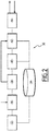
- the figure 2 schematically illustrates the main functional blocks of a radio wave transmission-reception radio device according to one embodiment, integrable in a radio altimeter and allowing selection of an antenna opening value among a plurality of values of Antenna opening.
- the radio device 30 comprises an input interface module 32 for acquiring various operating parameters, to be stored in a memory 34 and a module 36 for obtaining an antenna opening value.
- the module 36 receives an antenna opening value from an operator.
- the module 36 receives an antenna opening value from another calculation module, for a loop operation to select an optimized antenna opening value for a given application, for example for a calculation of height H 0 when the radio device 30 is integrated in a radio altimeter.
- the radio device 30 comprises a radio wave generation module 38 in a first frequency band, for example the C band.
- a radio wave wave transposition module 40 in a second frequency band is implemented optionally, depending on the chosen aperture value obtained by the module 36 for obtaining an aperture value of antenna.
- the second frequency band is the Ka band.
- the emission of the radio wave is in the first frequency band, which is lower than the second frequency band.
- the modules 38 and 40 are replaced by a single module for generating and shaping a radio wave in a frequency band selected by a parameter.
- a control module 42 makes it possible to select the radiating elements of the antenna system 44 to be used in transmission and reception.
- the antenna system 44 comprises a first array of radiating elements capable of transmitting in the first frequency band.
- It also comprises a set of second networks of radiating elements capable of transmitting in the second frequency band.
- the figure 3 schematically illustrates an antenna system 44 according to one embodiment.
- the system comprises a first network 45 of first radiating elements operating in the low band 46a, 46b, 46c and 46d, positioned on a support reflector plane 48 and each having a power supply point 50a, 50b, 50c and 50d. Each of the first radiating elements is activated when it is powered.
- Each of these second networks of radiating elements is composed of a regular block of radiating elements or elementary patches 54, arranged in a regular mesh.
- the regular mesh is square, but any other regular mesh is conceivable.
- the second radiating elements are arranged in concentric rings.
- the second networks 52 1 to 52 n are also arranged in a matrix 55 of second arrays of radiating elements.
- Each of the second networks of radiating elements 52 i includes a power supply point 58 i , to enable or disable this network transmission and reception.
- each of these second radiating element arrays 52 i is individually activatable, which allows various selections of sets of second arrays activated by the control module 42, forming a transmission-reception configuration of second arrays.
- radiating element adapted to emit and receive a radio wave beam corresponding to a different antenna opening value.
- An antenna system with multiple selectable antenna opening values is obtained.
- the activation of the first network 45 of radiating elements makes it possible to obtain the reception zone 14 of the figure 1
- the activation of the entire matrix 55 of second networks makes it possible to obtain the reception zone 20 of the figure 1 .
- the activation of the set of second networks of radiating elements forming the sub-matrix 56 makes it possible to obtain the reception zone 18 and the activation of a single square 52 i makes it possible to obtain the zone 16.
- the figure 4 schematically illustrates a circuit 60 for activation / deactivation of the radiating element arrays of the figure 3 .
- the electrical circuit 60 includes a feed point 62 of the first array of radiating elements, and power supply points 64, 66, 68 of the sets of second networks considered.
- each of the sets of first and second arrays of radiating elements associated with an antenna aperture value has an associated feed point.
- the circuit of the figure 4 has switches 70 1 , ..., 70 k , ... 70 n to feed or not the first and second networks of radiating elements.
- the elements 70 1 , ..., 70 k , ... 70 n of activation / deactivation are switches.
- Various opening / closing configurations of the activation elements 70 1 to 70 n are provided, each configuration corresponding to a set of activated radiating element arrays and to a given antenna opening value.
- the various configurations indicating the correspondence between the positions of the various switches and the associated antenna opening value, are stored in a memory module 34, for example in registers or in a file.
- the choice of the antenna opening associated with the antenna system 44 is made by selecting the position of the various activation elements of the circuit 60.
- a discrete set of different antenna aperture values can be obtained.
- a radioaltimeter capable of being fixed to an airborne system and of providing a distance from said airborne system with respect to a surface, comprises a radio frequency transmission / reception device as described above and a processing module adapted to calculate said distance as a function of radio waves emitted and reflected.
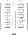
- the figure 5 is a flowchart of the main steps implemented by a radioaltimeter comprising a radiofrequency device as described above, for a distance calculation with respect to a surface overflown.
- an antenna opening value V A to be applied is obtained, either via a human-machine interface under the control of an operator, or by calculation as explained below.
- a beam of radio waves to be transmitted is generated during a step 82, in a first frequency band, for example the C band.
- step 84 is followed by a transposition step 86 in order to transpose the radio waves to be emitted in the second frequency band, for example the Ka band.
- the step 88 of selection of emission radiating element networks consists in determining, as a function of the antenna opening value. V A , from previously stored configurations matching the various possible antenna aperture values with an open / close configuration of the switches of the control circuit.
- the antenna aperture value V A is the maximum aperture value
- only the first array of radiating elements is activated.
- Step 88 of choice of radiating emission element networks applies an activation / deactivation control of the switches allowing the power supply of the various networks of selected radiating elements and the emission of the radio waves.
- an activation / deactivation of the networks of radiating elements is also implemented during a step 90, as a function of the antenna opening value V A.
- Step 90 is followed by a verification step 92, similar to step 84, in order to verify whether the antenna opening value V A is equal to a maximum opening value previously stored.
- step 92 is followed by a transposition step 94 in order to transpose the radio waves received in the first frequency band.
- the step 96 implements the various operations of reception and demodulation of the received radio waves, transposed, if necessary, in the first band frequency.
- a step 98 for extracting and calculating the distance between the radioaltimeter and the surface having reflected the radio waves received is applied.
- the radio altimeter determines, according to its own methods and according to its mission, that the zone of reception analyzed is not satisfactory, it can command a new value of antenna opening.
- this embodiment implements radio wave processing operations in the first frequency band, which are conventional.
- a known radio altimeter in C-band, modified by adding modules for obtaining an antenna opening value, of transposition between said first and second frequency bands and of activation / deactivation control of the element networks.
- radiators for use in transmission and reception is usable.
- the proposed solution has low manufacturing costs, while maintaining the compactness of the device.
- the invention has been described in its application to a radiofrequency device capable of transmitting and receiving in two different frequency bands.
- the invention is not limited to this case of application, and is applicable for operation with more two frequency bands, networks of radiating elements being selectable in each frequency band to achieve various values of antenna opening.
Landscapes
- Engineering & Computer Science (AREA)
- Radar, Positioning & Navigation (AREA)
- Remote Sensing (AREA)
- Physics & Mathematics (AREA)
- Computer Networks & Wireless Communication (AREA)
- General Physics & Mathematics (AREA)
- Electromagnetism (AREA)
- Radar Systems Or Details Thereof (AREA)
- Details Of Aerials (AREA)
- Variable-Direction Aerials And Aerial Arrays (AREA)
Applications Claiming Priority (1)
| Application Number | Priority Date | Filing Date | Title |
|---|---|---|---|
| FR1501559A FR3039328B1 (fr) | 2015-07-22 | 2015-07-22 | Dispositif radioelectrique d'emission-reception d'ondes radioelectriques et systeme de radio altimetrie associe |
Publications (2)
| Publication Number | Publication Date |
|---|---|
| EP3121902A1 EP3121902A1 (fr) | 2017-01-25 |
| EP3121902B1 true EP3121902B1 (fr) | 2018-11-14 |
Family
ID=55022504
Family Applications (1)
| Application Number | Title | Priority Date | Filing Date |
|---|---|---|---|
| EP16180427.3A Active EP3121902B1 (fr) | 2015-07-22 | 2016-07-20 | Dispositif radioélectrique d'émission-réception d'ondes radioélectriques et système de radio altimétrie associé |
Country Status (7)
| Country | Link |
|---|---|
| US (1) | US10502825B2 (enExample) |
| EP (1) | EP3121902B1 (enExample) |
| JP (1) | JP6870932B2 (enExample) |
| KR (1) | KR20170012142A (enExample) |
| ES (1) | ES2715015T3 (enExample) |
| FR (1) | FR3039328B1 (enExample) |
| IL (1) | IL246878B (enExample) |
Cited By (1)
| Publication number | Priority date | Publication date | Assignee | Title |
|---|---|---|---|---|
| EP4607243A1 (fr) * | 2024-02-23 | 2025-08-27 | Airbus Helicopters | Radioaltimetre pour aeronef ayant un angle d ouverture reglable et procede de mesure d'une hauteur-sol au moyen de ce radioaltimetre |
Families Citing this family (7)
| Publication number | Priority date | Publication date | Assignee | Title |
|---|---|---|---|---|
| FR3069523A1 (fr) * | 2017-07-27 | 2019-02-01 | Prodose | Procede de realisation d'un reseau pour la fourniture notamment d'internet sur toute la surface du globe terrestre, avion permettant de le mettre en oeuvre |
| GB2569620B (en) * | 2017-12-21 | 2021-12-29 | Canon Kk | Optimization of the performances of an antenna array |
| FR3090895B1 (fr) * | 2018-12-20 | 2020-12-25 | Thales Sa | Procede et systeme radar de proximite pour aeronef a voilure tournante |
| FR3103569B1 (fr) * | 2019-11-27 | 2021-12-10 | Thales Sa | Radar, engin volant comportant un tel radar, procede de traitement dans un radar embarque dans un engin volant et programme d'ordinateur associe |
| FR3113200B1 (fr) * | 2020-07-29 | 2023-12-15 | Thales Sa | Systeme d'antenne multifaisceaux concentriques et procede d'emission associe |
| KR102325365B1 (ko) * | 2021-05-04 | 2021-11-10 | 국방과학연구소 | 고도별 개별 임무 수행이 가능한 간섭계 레이더 고도계와 전파 고도계의 소형 통합 장치 및 그 운용 방법 |
| US20250175217A1 (en) * | 2022-02-17 | 2025-05-29 | NEC Laboratories Europe GmbH | Multi-frequency ris architecture |
Family Cites Families (13)
| Publication number | Priority date | Publication date | Assignee | Title |
|---|---|---|---|---|
| FR1501559A (fr) * | 1966-11-17 | 1967-11-10 | Appareil photographique professionnel à chargement et déchargement rapides et multiples par plan-films | |
| GB2157500B (en) * | 1984-04-11 | 1987-07-01 | Plessey Co Plc | Microwave antenna |
| JPH02287181A (ja) * | 1989-04-27 | 1990-11-27 | Matsushita Electric Works Ltd | 車載用レーダシステム |
| JPH03119779U (enExample) * | 1990-03-20 | 1991-12-10 | ||
| JPH0440003A (ja) * | 1990-06-05 | 1992-02-10 | Mitsubishi Electric Corp | 多層化アレイアンテナ |
| US5549002A (en) * | 1994-07-01 | 1996-08-27 | General Electric Company | Method for detecting and characterizing flaws in engineering materials |
| GB2330236A (en) * | 1997-10-11 | 1999-04-14 | Secr Defence | A dual band phased array antenna |
| JP4558548B2 (ja) * | 2005-03-15 | 2010-10-06 | 株式会社リコー | マイクロストリップアンテナ、無線モジュール、無線システム及びマイクロストリップアンテナの制御方法 |
| JP4654803B2 (ja) * | 2005-07-07 | 2011-03-23 | 日産自動車株式会社 | 車両周辺監視用レーダ装置 |
| DE102006032539A1 (de) * | 2006-07-13 | 2008-01-17 | Robert Bosch Gmbh | FMCW-Radarsensor |
| GB0902314D0 (en) * | 2009-02-12 | 2009-04-01 | Trw Ltd | Antennas |
| KR101223804B1 (ko) * | 2011-01-25 | 2013-01-17 | 주식회사 만도 | 감지 센서 |
| US8903454B2 (en) * | 2011-11-07 | 2014-12-02 | Alcatel Lucent | Base station and radio unit for creating overlaid sectors with carrier aggregation |
-
2015
- 2015-07-22 FR FR1501559A patent/FR3039328B1/fr not_active Expired - Fee Related
-
2016
- 2016-07-20 EP EP16180427.3A patent/EP3121902B1/fr active Active
- 2016-07-20 ES ES16180427T patent/ES2715015T3/es active Active
- 2016-07-21 IL IL246878A patent/IL246878B/en active IP Right Grant
- 2016-07-21 US US15/216,530 patent/US10502825B2/en active Active
- 2016-07-21 JP JP2016143765A patent/JP6870932B2/ja active Active
- 2016-07-22 KR KR1020160093689A patent/KR20170012142A/ko not_active Ceased
Non-Patent Citations (1)
| Title |
|---|
| None * |
Cited By (2)
| Publication number | Priority date | Publication date | Assignee | Title |
|---|---|---|---|---|
| EP4607243A1 (fr) * | 2024-02-23 | 2025-08-27 | Airbus Helicopters | Radioaltimetre pour aeronef ayant un angle d ouverture reglable et procede de mesure d'une hauteur-sol au moyen de ce radioaltimetre |
| FR3159675A1 (fr) * | 2024-02-23 | 2025-08-29 | Airbus Helicopters | Radioaltimètre pour aéronef ayant un angle d’ouverture réglable et procédé de mesure d’une hauteur-sol au moyen de ce radioaltimètre |
Also Published As
| Publication number | Publication date |
|---|---|
| JP2017026618A (ja) | 2017-02-02 |
| US10502825B2 (en) | 2019-12-10 |
| FR3039328B1 (fr) | 2017-08-25 |
| US20170227635A1 (en) | 2017-08-10 |
| ES2715015T3 (es) | 2019-05-31 |
| IL246878A0 (en) | 2016-12-29 |
| JP6870932B2 (ja) | 2021-05-12 |
| EP3121902A1 (fr) | 2017-01-25 |
| IL246878B (en) | 2020-08-31 |
| FR3039328A1 (fr) | 2017-01-27 |
| KR20170012142A (ko) | 2017-02-02 |
Similar Documents
| Publication | Publication Date | Title |
|---|---|---|
| EP3121902B1 (fr) | Dispositif radioélectrique d'émission-réception d'ondes radioélectriques et système de radio altimétrie associé | |
| US11582305B2 (en) | Vehicle radar system with a shared radar and communication system | |
| EP2831615B1 (fr) | Dispositif de détection électromagnétique actif et passif à faible probabilité d'interception | |
| CN104011558B (zh) | 编码的孔径波束分析方法和设备 | |
| EP2296007B1 (fr) | Radar à agilité de faisceau, notamment pour la fonction de détection et d'évitement d'obstacles | |
| US11336373B2 (en) | Co-prime optical transceiver array | |
| US10768276B2 (en) | Decentralised radar system | |
| FR3058227A1 (fr) | Radar fmcw multifaisceaux, notamment pour automobile | |
| EP2287633B1 (fr) | Radar de détection de cibles aériennes équipant un aéronef notamment pour l'évitement d'obstacles en vol | |
| RU2444755C1 (ru) | Способ обнаружения и пространственной локализации воздушных объектов | |
| WO2021058674A1 (fr) | Procede d'imagerie radar, et radar mettant en œuvre un tel procede | |
| EP2612166A1 (fr) | Procédé et dispositif de localisation d'au moins un obstacle dans un réseau de communication, programme d'ordinateur correspondant | |
| FR2959318A1 (fr) | Localisation continue de grande precision | |
| EP2435847B1 (fr) | Procede et systeme pour la determination de la direction d'arrivee d'une onde electromagnetique de polarisation quelconque | |
| EP3321711B1 (fr) | Dispositif de reception pour antenne a balayage electronique apte a fonctionner en mode radar et resm, et radar equipe d'un tel dispositif | |
| EP2673651B1 (fr) | Dispositif de reception large bande par autotransposition et application a la detection et a la caracterisation d'emissions radioelectriques | |
| EP2653887B1 (fr) | Système de radio adapté pour fonctionner dans une installation de radio altimétrie multiple | |
| EP3420642B1 (fr) | Capteur intégré d'interception des émissions radioélectriques com/rad | |
| US11035947B2 (en) | Radio frequency (RF) ranging in propagation limited RF environments | |
| FR2984521A1 (fr) | Senseur radioelectrique apte a etre fixe a un aeronef et a fournir une information de distance par rapport a une surface | |
| EP4050376A1 (fr) | Systeme radar d'imagerie de proximite a antenne multivoies | |
| EP2653888B1 (fr) | Système de radio altimétrie adapté pour fonctionner dans une installation de radio altimétrie duale | |
| CN120233307A (zh) | 支持对象反射信号重叠检测的mimo雷达 | |
| EP3521851A1 (fr) | Dispositif et procédé d'émission/réception de signaux radioélectriques | |
| Poliakov | Virtual Receiving Array Method for Direction of Arrival Estimation Using Direct Data Domain Techniques and Signal Cyclostationarity |
Legal Events
| Date | Code | Title | Description |
|---|---|---|---|
| PUAI | Public reference made under article 153(3) epc to a published international application that has entered the european phase |
Free format text: ORIGINAL CODE: 0009012 |
|
| STAA | Information on the status of an ep patent application or granted ep patent |
Free format text: STATUS: THE APPLICATION HAS BEEN PUBLISHED |
|
| AK | Designated contracting states |
Kind code of ref document: A1 Designated state(s): AL AT BE BG CH CY CZ DE DK EE ES FI FR GB GR HR HU IE IS IT LI LT LU LV MC MK MT NL NO PL PT RO RS SE SI SK SM TR |
|
| AX | Request for extension of the european patent |
Extension state: BA ME |
|
| STAA | Information on the status of an ep patent application or granted ep patent |
Free format text: STATUS: REQUEST FOR EXAMINATION WAS MADE |
|
| 17P | Request for examination filed |
Effective date: 20170623 |
|
| RBV | Designated contracting states (corrected) |
Designated state(s): AL AT BE BG CH CY CZ DE DK EE ES FI FR GB GR HR HU IE IS IT LI LT LU LV MC MK MT NL NO PL PT RO RS SE SI SK SM TR |
|
| GRAP | Despatch of communication of intention to grant a patent |
Free format text: ORIGINAL CODE: EPIDOSNIGR1 |
|
| STAA | Information on the status of an ep patent application or granted ep patent |
Free format text: STATUS: GRANT OF PATENT IS INTENDED |
|
| RIC1 | Information provided on ipc code assigned before grant |
Ipc: H01Q 3/01 20060101ALI20180424BHEP Ipc: G01S 13/34 20060101ALI20180424BHEP Ipc: H01Q 25/00 20060101AFI20180424BHEP Ipc: H01Q 21/30 20060101ALI20180424BHEP Ipc: G01S 13/88 20060101ALI20180424BHEP |
|
| INTG | Intention to grant announced |
Effective date: 20180528 |
|
| RIN1 | Information on inventor provided before grant (corrected) |
Inventor name: TCHOFFO-TALOM, FRIEDMAN Inventor name: LYS, SEBASTIEN |
|
| GRAS | Grant fee paid |
Free format text: ORIGINAL CODE: EPIDOSNIGR3 |
|
| GRAA | (expected) grant |
Free format text: ORIGINAL CODE: 0009210 |
|
| STAA | Information on the status of an ep patent application or granted ep patent |
Free format text: STATUS: THE PATENT HAS BEEN GRANTED |
|
| AK | Designated contracting states |
Kind code of ref document: B1 Designated state(s): AL AT BE BG CH CY CZ DE DK EE ES FI FR GB GR HR HU IE IS IT LI LT LU LV MC MK MT NL NO PL PT RO RS SE SI SK SM TR |
|
| REG | Reference to a national code |
Ref country code: CH Ref legal event code: EP Ref country code: AT Ref legal event code: REF Ref document number: 1065937 Country of ref document: AT Kind code of ref document: T Effective date: 20181115 |
|
| REG | Reference to a national code |
Ref country code: DE Ref legal event code: R096 Ref document number: 602016007090 Country of ref document: DE |
|
| REG | Reference to a national code |
Ref country code: IE Ref legal event code: FG4D Free format text: LANGUAGE OF EP DOCUMENT: FRENCH |
|
| REG | Reference to a national code |
Ref country code: NL Ref legal event code: MP Effective date: 20181114 |
|
| REG | Reference to a national code |
Ref country code: LT Ref legal event code: MG4D |
|
| REG | Reference to a national code |
Ref country code: AT Ref legal event code: MK05 Ref document number: 1065937 Country of ref document: AT Kind code of ref document: T Effective date: 20181114 |
|
| PG25 | Lapsed in a contracting state [announced via postgrant information from national office to epo] |
Ref country code: AT Free format text: LAPSE BECAUSE OF FAILURE TO SUBMIT A TRANSLATION OF THE DESCRIPTION OR TO PAY THE FEE WITHIN THE PRESCRIBED TIME-LIMIT Effective date: 20181114 Ref country code: HR Free format text: LAPSE BECAUSE OF FAILURE TO SUBMIT A TRANSLATION OF THE DESCRIPTION OR TO PAY THE FEE WITHIN THE PRESCRIBED TIME-LIMIT Effective date: 20181114 Ref country code: NO Free format text: LAPSE BECAUSE OF FAILURE TO SUBMIT A TRANSLATION OF THE DESCRIPTION OR TO PAY THE FEE WITHIN THE PRESCRIBED TIME-LIMIT Effective date: 20190214 Ref country code: LV Free format text: LAPSE BECAUSE OF FAILURE TO SUBMIT A TRANSLATION OF THE DESCRIPTION OR TO PAY THE FEE WITHIN THE PRESCRIBED TIME-LIMIT Effective date: 20181114 Ref country code: BG Free format text: LAPSE BECAUSE OF FAILURE TO SUBMIT A TRANSLATION OF THE DESCRIPTION OR TO PAY THE FEE WITHIN THE PRESCRIBED TIME-LIMIT Effective date: 20190214 Ref country code: LT Free format text: LAPSE BECAUSE OF FAILURE TO SUBMIT A TRANSLATION OF THE DESCRIPTION OR TO PAY THE FEE WITHIN THE PRESCRIBED TIME-LIMIT Effective date: 20181114 Ref country code: IS Free format text: LAPSE BECAUSE OF FAILURE TO SUBMIT A TRANSLATION OF THE DESCRIPTION OR TO PAY THE FEE WITHIN THE PRESCRIBED TIME-LIMIT Effective date: 20190314 Ref country code: FI Free format text: LAPSE BECAUSE OF FAILURE TO SUBMIT A TRANSLATION OF THE DESCRIPTION OR TO PAY THE FEE WITHIN THE PRESCRIBED TIME-LIMIT Effective date: 20181114 |
|
| PG25 | Lapsed in a contracting state [announced via postgrant information from national office to epo] |
Ref country code: GR Free format text: LAPSE BECAUSE OF FAILURE TO SUBMIT A TRANSLATION OF THE DESCRIPTION OR TO PAY THE FEE WITHIN THE PRESCRIBED TIME-LIMIT Effective date: 20190215 Ref country code: SE Free format text: LAPSE BECAUSE OF FAILURE TO SUBMIT A TRANSLATION OF THE DESCRIPTION OR TO PAY THE FEE WITHIN THE PRESCRIBED TIME-LIMIT Effective date: 20181114 Ref country code: RS Free format text: LAPSE BECAUSE OF FAILURE TO SUBMIT A TRANSLATION OF THE DESCRIPTION OR TO PAY THE FEE WITHIN THE PRESCRIBED TIME-LIMIT Effective date: 20181114 Ref country code: PT Free format text: LAPSE BECAUSE OF FAILURE TO SUBMIT A TRANSLATION OF THE DESCRIPTION OR TO PAY THE FEE WITHIN THE PRESCRIBED TIME-LIMIT Effective date: 20190314 Ref country code: AL Free format text: LAPSE BECAUSE OF FAILURE TO SUBMIT A TRANSLATION OF THE DESCRIPTION OR TO PAY THE FEE WITHIN THE PRESCRIBED TIME-LIMIT Effective date: 20181114 Ref country code: NL Free format text: LAPSE BECAUSE OF FAILURE TO SUBMIT A TRANSLATION OF THE DESCRIPTION OR TO PAY THE FEE WITHIN THE PRESCRIBED TIME-LIMIT Effective date: 20181114 |
|
| PG25 | Lapsed in a contracting state [announced via postgrant information from national office to epo] |
Ref country code: DK Free format text: LAPSE BECAUSE OF FAILURE TO SUBMIT A TRANSLATION OF THE DESCRIPTION OR TO PAY THE FEE WITHIN THE PRESCRIBED TIME-LIMIT Effective date: 20181114 Ref country code: PL Free format text: LAPSE BECAUSE OF FAILURE TO SUBMIT A TRANSLATION OF THE DESCRIPTION OR TO PAY THE FEE WITHIN THE PRESCRIBED TIME-LIMIT Effective date: 20181114 Ref country code: CZ Free format text: LAPSE BECAUSE OF FAILURE TO SUBMIT A TRANSLATION OF THE DESCRIPTION OR TO PAY THE FEE WITHIN THE PRESCRIBED TIME-LIMIT Effective date: 20181114 |
|
| REG | Reference to a national code |
Ref country code: DE Ref legal event code: R097 Ref document number: 602016007090 Country of ref document: DE |
|
| PG25 | Lapsed in a contracting state [announced via postgrant information from national office to epo] |
Ref country code: RO Free format text: LAPSE BECAUSE OF FAILURE TO SUBMIT A TRANSLATION OF THE DESCRIPTION OR TO PAY THE FEE WITHIN THE PRESCRIBED TIME-LIMIT Effective date: 20181114 Ref country code: SK Free format text: LAPSE BECAUSE OF FAILURE TO SUBMIT A TRANSLATION OF THE DESCRIPTION OR TO PAY THE FEE WITHIN THE PRESCRIBED TIME-LIMIT Effective date: 20181114 Ref country code: EE Free format text: LAPSE BECAUSE OF FAILURE TO SUBMIT A TRANSLATION OF THE DESCRIPTION OR TO PAY THE FEE WITHIN THE PRESCRIBED TIME-LIMIT Effective date: 20181114 Ref country code: SM Free format text: LAPSE BECAUSE OF FAILURE TO SUBMIT A TRANSLATION OF THE DESCRIPTION OR TO PAY THE FEE WITHIN THE PRESCRIBED TIME-LIMIT Effective date: 20181114 |
|
| PLBE | No opposition filed within time limit |
Free format text: ORIGINAL CODE: 0009261 |
|
| STAA | Information on the status of an ep patent application or granted ep patent |
Free format text: STATUS: NO OPPOSITION FILED WITHIN TIME LIMIT |
|
| 26N | No opposition filed |
Effective date: 20190815 |
|
| PG25 | Lapsed in a contracting state [announced via postgrant information from national office to epo] |
Ref country code: SI Free format text: LAPSE BECAUSE OF FAILURE TO SUBMIT A TRANSLATION OF THE DESCRIPTION OR TO PAY THE FEE WITHIN THE PRESCRIBED TIME-LIMIT Effective date: 20181114 |
|
| PG25 | Lapsed in a contracting state [announced via postgrant information from national office to epo] |
Ref country code: MC Free format text: LAPSE BECAUSE OF FAILURE TO SUBMIT A TRANSLATION OF THE DESCRIPTION OR TO PAY THE FEE WITHIN THE PRESCRIBED TIME-LIMIT Effective date: 20181114 |
|
| REG | Reference to a national code |
Ref country code: CH Ref legal event code: PL |
|
| PG25 | Lapsed in a contracting state [announced via postgrant information from national office to epo] |
Ref country code: TR Free format text: LAPSE BECAUSE OF FAILURE TO SUBMIT A TRANSLATION OF THE DESCRIPTION OR TO PAY THE FEE WITHIN THE PRESCRIBED TIME-LIMIT Effective date: 20181114 |
|
| REG | Reference to a national code |
Ref country code: BE Ref legal event code: MM Effective date: 20190731 |
|
| PG25 | Lapsed in a contracting state [announced via postgrant information from national office to epo] |
Ref country code: LI Free format text: LAPSE BECAUSE OF NON-PAYMENT OF DUE FEES Effective date: 20190731 Ref country code: CH Free format text: LAPSE BECAUSE OF NON-PAYMENT OF DUE FEES Effective date: 20190731 Ref country code: LU Free format text: LAPSE BECAUSE OF NON-PAYMENT OF DUE FEES Effective date: 20190720 Ref country code: BE Free format text: LAPSE BECAUSE OF NON-PAYMENT OF DUE FEES Effective date: 20190731 |
|
| PG25 | Lapsed in a contracting state [announced via postgrant information from national office to epo] |
Ref country code: IE Free format text: LAPSE BECAUSE OF NON-PAYMENT OF DUE FEES Effective date: 20190720 |
|
| PG25 | Lapsed in a contracting state [announced via postgrant information from national office to epo] |
Ref country code: CY Free format text: LAPSE BECAUSE OF FAILURE TO SUBMIT A TRANSLATION OF THE DESCRIPTION OR TO PAY THE FEE WITHIN THE PRESCRIBED TIME-LIMIT Effective date: 20181114 |
|
| PG25 | Lapsed in a contracting state [announced via postgrant information from national office to epo] |
Ref country code: MT Free format text: LAPSE BECAUSE OF FAILURE TO SUBMIT A TRANSLATION OF THE DESCRIPTION OR TO PAY THE FEE WITHIN THE PRESCRIBED TIME-LIMIT Effective date: 20181114 Ref country code: HU Free format text: LAPSE BECAUSE OF FAILURE TO SUBMIT A TRANSLATION OF THE DESCRIPTION OR TO PAY THE FEE WITHIN THE PRESCRIBED TIME-LIMIT; INVALID AB INITIO Effective date: 20160720 |
|
| PG25 | Lapsed in a contracting state [announced via postgrant information from national office to epo] |
Ref country code: MK Free format text: LAPSE BECAUSE OF FAILURE TO SUBMIT A TRANSLATION OF THE DESCRIPTION OR TO PAY THE FEE WITHIN THE PRESCRIBED TIME-LIMIT Effective date: 20181114 |
|
| P01 | Opt-out of the competence of the unified patent court (upc) registered |
Effective date: 20230522 |
|
| PGFP | Annual fee paid to national office [announced via postgrant information from national office to epo] |
Ref country code: ES Payment date: 20250811 Year of fee payment: 10 |
|
| PGFP | Annual fee paid to national office [announced via postgrant information from national office to epo] |
Ref country code: DE Payment date: 20250711 Year of fee payment: 10 |
|
| PGFP | Annual fee paid to national office [announced via postgrant information from national office to epo] |
Ref country code: IT Payment date: 20250714 Year of fee payment: 10 |
|
| PGFP | Annual fee paid to national office [announced via postgrant information from national office to epo] |
Ref country code: GB Payment date: 20250723 Year of fee payment: 10 |
|
| PGFP | Annual fee paid to national office [announced via postgrant information from national office to epo] |
Ref country code: FR Payment date: 20250730 Year of fee payment: 10 |