EP3121502B1 - Bent pipe structure - Google Patents
Bent pipe structure Download PDFInfo
- Publication number
- EP3121502B1 EP3121502B1 EP15764657.1A EP15764657A EP3121502B1 EP 3121502 B1 EP3121502 B1 EP 3121502B1 EP 15764657 A EP15764657 A EP 15764657A EP 3121502 B1 EP3121502 B1 EP 3121502B1
- Authority
- EP
- European Patent Office
- Prior art keywords
- pipe body
- bend
- less
- cross
- axial line
- Prior art date
- Legal status (The legal status is an assumption and is not a legal conclusion. Google has not performed a legal analysis and makes no representation as to the accuracy of the status listed.)
- Active
Links
- 238000000926 separation method Methods 0.000 claims description 6
- 238000011156 evaluation Methods 0.000 description 30
- 230000000052 comparative effect Effects 0.000 description 28
- 238000000465 moulding Methods 0.000 description 21
- 239000012530 fluid Substances 0.000 description 18
- 230000009467 reduction Effects 0.000 description 3
- 229920003002 synthetic resin Polymers 0.000 description 2
- 239000000057 synthetic resin Substances 0.000 description 2
- 239000002826 coolant Substances 0.000 description 1
- 239000000498 cooling water Substances 0.000 description 1
- 230000000694 effects Effects 0.000 description 1
- 238000001746 injection moulding Methods 0.000 description 1
- 239000007788 liquid Substances 0.000 description 1
- 230000000116 mitigating effect Effects 0.000 description 1
- 239000000243 solution Substances 0.000 description 1
Images


Classifications
-
- F—MECHANICAL ENGINEERING; LIGHTING; HEATING; WEAPONS; BLASTING
- F16—ENGINEERING ELEMENTS AND UNITS; GENERAL MEASURES FOR PRODUCING AND MAINTAINING EFFECTIVE FUNCTIONING OF MACHINES OR INSTALLATIONS; THERMAL INSULATION IN GENERAL
- F16L—PIPES; JOINTS OR FITTINGS FOR PIPES; SUPPORTS FOR PIPES, CABLES OR PROTECTIVE TUBING; MEANS FOR THERMAL INSULATION IN GENERAL
- F16L43/00—Bends; Siphons
- F16L43/008—Bends; Siphons made from plastic material
-
- B—PERFORMING OPERATIONS; TRANSPORTING
- B29—WORKING OF PLASTICS; WORKING OF SUBSTANCES IN A PLASTIC STATE IN GENERAL
- B29C—SHAPING OR JOINING OF PLASTICS; SHAPING OF MATERIAL IN A PLASTIC STATE, NOT OTHERWISE PROVIDED FOR; AFTER-TREATMENT OF THE SHAPED PRODUCTS, e.g. REPAIRING
- B29C45/00—Injection moulding, i.e. forcing the required volume of moulding material through a nozzle into a closed mould; Apparatus therefor
- B29C45/17—Component parts, details or accessories; Auxiliary operations
- B29C45/40—Removing or ejecting moulded articles
- B29C45/44—Removing or ejecting moulded articles for undercut articles
- B29C45/4421—Removing or ejecting moulded articles for undercut articles using expansible or collapsible cores
-
- B—PERFORMING OPERATIONS; TRANSPORTING
- B29—WORKING OF PLASTICS; WORKING OF SUBSTANCES IN A PLASTIC STATE IN GENERAL
- B29L—INDEXING SCHEME ASSOCIATED WITH SUBCLASS B29C, RELATING TO PARTICULAR ARTICLES
- B29L2031/00—Other particular articles
- B29L2031/24—Pipe joints or couplings
- B29L2031/243—Elbows
Definitions
- the present invention relates to a bent pipe structure to be employed in a bent part of piping that configures a fluid flow path.
- Patent Document 1 Japanese Patent Application Laid-Open ( JP-A) No. 2001-219453 ) describes a bent pipe molding mold configured from an outer mold and an inner mold.
- the outer mold which forms an outer face of the bent pipe, is configured by a two-piece split mold structure for molding the outer face of the bent pipe.
- the inner mold which forms an inner face of the bent pipe, has a structure that is configured by members capable of being separated from each other or combined with each other in directions relatively approaching or moving apart along a direction of an axial line of the bent pipe.
- Documents US 2,303,949 A1 and JP 62-13292 U describe a conduit bend with a cross-sectional area enlargement portion at an inner circumferential face.
- An object of the present invention is, in a bend of a pipe body, to mitigate an increase in pressure drop in fluid flowing through the bend.
- a bent pipe structure of a first aspect of the present invention includes a pipe body that includes a bend, and a cross-sectional area enlargement portion that is formed by configuring a curved portion with a circular arc shape at an inner circumferential face on a bend direction inside of the bend so as to enlarge a cross-sectional area of a flow path of the pipe body.
- the cross-sectional area enlargement portion includes a pair of side face portions that face each other along an orthogonal direction orthogonal to an axial line of the pipe body, and a bottom face portion that couples lower ends of the side face portions together.
- the cross-sectional area enlargement portion When viewed along the direction of the axial line, the cross-sectional area enlargement portion is formed in a curved shape that protrudes toward an outer circumferential side of the pipe body.
- the bent pipe structure satisfies the following relationships, wherein P (mm) denotes the inner diameter of the pipe body, H (mm) denotes the separation distance between the pair of side face portions, as viewed along the direction of the axial line, and R (mm) denotes the radius of the curved portion:
- the cross-sectional area enlargement portion is formed by configuring the curved portion of the inner circumferential face with a circular arc shape at the inner circumferential face on a bend direction inside of the bend of the pipe body so as to enlarge a cross-sectional area of the flow path of the pipe body. Moreover, when viewed along the direction of the axial line, the cross-sectional area enlargement portion is formed in a curved shape that protrudes toward an outer circumferential side of the pipe body.
- the bent pipe structure satisfies specific relationships, where P (mm) denotes the inner diameter of the pipe body, H (mm) denotes the separation distance between the pair of side face portions, as viewed along the direction of the axial line, and R (mm) denotes the radius of the curved portion.
- an increase in pressure drop in fluid flowing through the bend may be mitigated at the bend of the pipe body.
- a bent pipe structure of a second aspect of the present invention includes a pipe body that includes a bend and a cross-sectional area enlargement portion that is formed by configuring a curved portion with a circular arc shape at an inner circumferential face on a bend direction inside of the bend so as to enlarge a cross-sectional area of a flow path of the pipe body.
- the cross-sectional area enlargement portion includes a pair of side face portions that face each other along an orthogonal direction orthogonal to an axial line of the pipe body, and a bottom face portion that couples lower ends of the side face portions together.
- the side face portions When viewed along the direction of the axial line, the side face portions are formed with straight lines and the bottom face portion is formed in a curved shape that protrudes toward an outer circumferential side of the pipe body.
- the bent pipe structure satisfies the following relationships, wherein P (mm) denotes the inner diameter of the pipe body, H (mm) denotes the separation distance between the pair of side face portions, as viewed along the direction of the axial line, and R (mm) denotes the radius of the curved portion.
- the cross-sectional area enlargement portion is formed by configuring the curved portion of the inner circumferential face with a circular arc shape at the inner circumferential face on a bend direction inside of the bend of the pipe body so as to enlarge a cross-sectional area of the flow path of the pipe body.
- the side face portions are formed with straight lines and the bottom face portion is formed in a curved shape that protrudes toward an outer circumferential side of the pipe body.
- the bent pipe structure satisfies specific relationships, where P (mm) denotes the inner diameter of the pipe body, H (mm) denotes the separation distance between the pair of side face portions, as viewed along the direction of the axial line, and R (mm) denotes the radius of the curved portion.
- an increase in pressure drop in fluid flowing through the bend may be mitigated at the bend of the pipe body.
- the present invention is, in a bend of a pipe body, capable of mitigating an increase in pressure drop in fluid flowing through the bend.
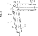
- a flow path with a circular cross-section is formed running along an axial line 13 of a pipe body 12 of a bent pipe 10, and the pipe body 12 includes a bend 14 at a part where the axial line 13 is bent at substantially a right angle.
- the axial line 13 is configured from a first straight line portion 13A extending in a straight line shape at an entrance side of the pipe body 12, a second straight line portion 13B extending in a straight line shape at an exit of the pipe body 12, and a circular arc portion 13C that has a circular arc shape and couples an end portion of the first straight line portion 13A and the second straight line portion 13B together.
- Both end portions 12B of the pipe body 12 are open, and, for example, both end portions 12B are respectively coupled to a hose 18.
- a curved portion 14A at an inner circumferential face 15 on a bend direction inside of the bend 14 is configured with a circular arc shape.
- a recess 16 serving as an example of a cross-sectional area enlargement portion that enlarges the cross-sectional area of the flow path of the pipe body 12 running along the direction of the axial line 13, is formed in the inner circumferential face 15 on the bend direction inside of the bend 14.
- the recess 16 enlarges the cross-sectional area of the flow path at the bend 14, such that when a fluid such as a liquid passes through the inside of the bend 14 (namely, a fluid flowing along arrow W in Fig. 1A ), an increase in pressure drop in the fluid can be suppressed at the recess 16.
- the bend direction inside is the side where the pipe body 12 is constricted along the bend direction (namely, the direction of the bend).
- a curved portion 104A at an inner circumferential face 105 on a bend direction inside of a bend 104 is configured by a sharp corner (namely, a state not configured by a circular arc shape).
- a recess that enlarges the cross-sectional area of a flow path of the pipe body 102 is not formed in the inner circumferential face 105 on the bend direction inside of the bend 104 of the bent pipe 100.
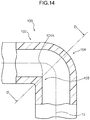
- a cross-section of the bend 104, sectioned along the bend 104 as viewed along an orthogonal direction that is orthogonal to the direction of the axial line 13 (a direction orthogonal to the first straight line portion 13A and the second straight line portion 13B, and the direction into the page in Fig. 2 and Fig. 14 ; referred to below as an "axis orthogonal direction") (a cross-section taken along line D-D in Fig. 14 ), has a shape as illustrated in Fig. 15 .
- the flow path in the cross-section of the bend 104 has an elliptical shape centered about the axial line 13.
- the flow path has an elliptical shape centered about the axial line 13 when viewing the flow path of the bend 104 along the direction of the axial line 13.
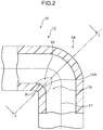
- the curved portion 14A at the inside of the bend 14 in the pipe body 12 of the bent pipe 10 has a curved arc shape as described above.
- the radius R illustrated in Fig. 2 denotes a curvature R of the curved portion 14A.
- the bend 14 is formed with the recess 16, described above, so as to enlarge the flow path with respect to the elliptical shape centered about the axial line 13.
- the recess 16 is configured from a pair of side face portions 16B that face each other along the axis orthogonal direction (the arrow Y direction in Fig. 3 ), and a bottom face portion 16A that couples respective lower ends of the side face portions 16B together.
- the recess 16 has a curved shape that protrudes toward the outer circumferential face of the pipe body 12. In other words, when viewing the flow path of the bend 14 along the direction of the axial line 13, the recess 16 has a curved shape that protrudes toward the outer circumferential face of the pipe body 12.
- the pair of side face portions 16B are configured with circular arc shapes having shapes that are symmetrical to each other, and the bottom face portion 16A is configured with a circular arc shape that smoothly links the pair of side face portions 16B together.
- the dimension H illustrated in Fig. 3 denotes the width of the recess 16 (width H).
- Fig. 1A , Fig. 1B , Fig. 2 , and Fig. 3 illustrate the shape of the pipe body 102 according to the comparative example with a double-dotted dashed line. Accordingly, in the bend 14 of the pipe body 12, it is apparent that due to forming the recess 16 in the bend 14, the cross-sectional area of the flow path of the bend 14 is enlarged compared to that of the bend 104 of the pipe body 102 according to the comparative example.
- the curvature R described above has a curvature that gradually changes so as to become 0 (mm) at end portions 16C of the recess 16 along the axis orthogonal direction.
- a bent pipe molding mold 20 of the present exemplary embodiment includes an outer mold 22 and an inner mold 24.
- the outer mold 22 has a two-piece split mold structure, and forms the outer circumferential face of the pipe body 12, which is made of synthetic resin and molded by injection molding.
- the inner mold 24 molds the inner circumferential face 15 of the pipe body 12.
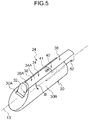
- the inner mold 24 includes a pair of primary cores 30 having the same shape as each other, and a pair of hinged cores 34 (secondary cores) having the same shape as each other and serving as secondary cores.
- Each primary core 30 and each hinged core 34 has an elongated shape running along the direction of the axial line 13 of the pipe body 12.
- the respective primary cores 30 and the respective hinged cores 34 can be separated from each other or combined with each other along the direction of the axial line 13 by being pulled apart from each other or being moved closer together along the direction of the axial line 13 of the pipe body 12.
- each primary core 30 is formed in each primary core 30 along the direction of the axial line 13 of the pipe body 12 at a location corresponding to the inner circumferential face 15 on the bend direction inside of the bend 14 (see Fig. 1 ).
- a leading end portion 30A of each primary core 30 accordingly has a shape that does not engage with an undercut portion of the recess 16 in the inner circumferential face 15 on the bend direction inside of the bend 14 of the pipe body 12.
- Each hinged core 34 is inserted into the respective grooves 32 of the primary cores 30 so as to be capable of sliding relative to the primary core 30 along the direction of the axial line 13 of the pipe body 12.
- the inner circumferential face 15 of the pipe body 12 is molded by curved molding faces 30B of the primary cores 30 and curved molding faces 34A of the hinged cores 34.
- Abase portion 36 at one length direction side of each hinged core 34 and a swinging portion 38 at another length direction side of each hinged core 34 are coupled together by a hinge 40.
- each swinging portions 38 swings with respect to the base portion 36 about an axis PI of the respective hinge 40, in a direction approaching the axial line 13 (arrow B direction in Fig. 5 ) and in a direction going away from the axial line 13 (direction opposite to that of arrow B in Fig. 5 ).
- each hinge 40 has a built-in coil spring 41, serving as a biasing means, and the respective swinging portion 38 swing with respect to the base portion 36 in the direction approaching the axial line 13 (the arrow B direction in Fig. 5 ) due to the biasing force of the coil spring 41.
- each swinging portion 38 is biased in the arrow B direction in Fig. 5 by the respective hinge 40, and is pressed against the bottom of the groove 32.
- Leading ends 38A of the swinging portions 38 of the respective hinged cores 34 correspond to the undercut portion of the recess 16 that is to be formed in the inner circumferential face 15 on the bend direction inside of the bend 14 of the pipe body 12, and have curved shapes that engage with the recess 16.
- the leading ends 38A of the swinging portions 38 of the pair of hinged cores 34 are positioned so as to form the recess 16, this being in the inner circumferential face 15 on the bend direction inside of the bend 14 of the pipe body 12.
- the swinging portions 38 of the pair of hinged cores 34 are housed in the respective groove 32 of each primary core 30, these being in the molding position.
- a synthetic resin is injected into the space formed between the outer mold 22 and the inner mold 24, and the pipe body 12 of the bent pipe that includes the recess 16 is molded. Then, the outer mold 22 is removed and the inner mold 24 is separated from the pipe body 12.
- the pair of primary cores 30 are separated by each being pulled, with respect to each of the pair of hinged cores 34, from the molding position illustrated in Fig. 7 , along the grooves 32 in a pull-out direction running along the axial line 13 (the arrow A direction in Fig. 8 ).
- the swinging portion 38 of each hinged core 34 swings through the respective hinge 40 toward the space at the molding position of the respective primary core 30 arising from moving the primary cores 30.
- the swinging portion 38 of each hinged core 34 thereby adopts the swung position illustrated in Fig. 8 .
- the proportional reductions in pressure drop in the pipe body 12 are all positive numerical values. Namely, due to forming the recess 16 configured with a curvature R and a width H as described in the evaluation specifications above in the pipe body 12, an increase in pressure drop in fluid flowing through the bend 14 can be suppressed compared to in the pipe body 102 according to the comparative example.
- a curved portion 64A at an inner circumferential face 65 at a bend direction inside of a bend 64 in a pipe body 62 of a bent pipe 60 is configured with a circular arc shape.
- a recess 66 serving as an example of a cross-sectional area enlargement portion that enlarges the cross-sectional area of the flow path of a pipe body 62 running along the direction of the axial line 13, is formed in the inner circumferential face 65 on the bend direction inside of the bend 64.
- the recess 66 is configured from a pair of side face portions 66B that face each other along the axis orthogonal direction (the direction into the page in Fig. 17 ), and a bottom face portion 66A that couples respective lower ends of the side face portions 66B together (see Fig. 18 ).
- the side face portions 66B have flat face shapes, and the bottom face portion 66A has a curved face shape.
- the radius R illustrated in Fig. 17 denotes a curvature R of the curved portion 64A.
- a cross-section of the bend 64 sectioned as viewed along the axis orthogonal direction (a cross-section taken along line K-K in Fig. 17 ), has a shape as illustrated in Fig. 18 .
- the flow path is enlarged with respect to an elliptical shape centered about the axial line 13.
- the recess 66 is configured from the pair of side face portions 66B and the bottom face portion 66A described above.
- the side face portions 66B are formed in straight lines
- the bottom face portion 66A is formed in a curved line shape that protrudes toward the outer circumferential side of the pipe body 62.
- the side face portions 66B are formed in straight lines
- the bottom face portion 66A is formed in a curved shape that protrudes toward the outer circumferential side of the pipe body 62.
- the dimension H illustrated in Fig. 18 denotes the width of the recess 66 (width H).
- the proportional reductions in pressure drop in the pipe body 62 are all positive numerical values. Namely, due to forming the pipe body 62 with the recess 66 configured with a curvature R and a width H as described in the evaluation specifications, an increase in pressure drop in fluid flowing through the bend 64 can be suppressed compared to in the pipe body 102 according to the comparative example.
- the present invention is not limited to these exemplary embodiments, and it would be obvious to a person having ordinary skill in the art that various other exemplary embodiments are possible within the scope of the present invention.
- the mold configuration explained in the above exemplary embodiments is merely exemplary, and the pipe body may be molded using nested molds or the like.
Landscapes
- Engineering & Computer Science (AREA)
- Mechanical Engineering (AREA)
- General Engineering & Computer Science (AREA)
- Manufacturing & Machinery (AREA)
- Branch Pipes, Bends, And The Like (AREA)
- Rigid Pipes And Flexible Pipes (AREA)
- Moulds For Moulding Plastics Or The Like (AREA)
Description
- The present invention relates to a bent pipe structure to be employed in a bent part of piping that configures a fluid flow path.
- Patent Document 1 (Japanese Patent Application Laid-Open (
JP-A) No. 2001-219453 US 2,303,949 A1 andJP 62-13292 U - However, in the configuration described in
Patent Document 1, a curved portion at a bend direction inside of a bend of a pipe body is configured by a sharp corner (namely, R = 0) rather than by a circular arc shape. Therefore, there is an increase in pressure drop in fluid flowing through the bend. - An object of the present invention is, in a bend of a pipe body, to mitigate an increase in pressure drop in fluid flowing through the bend.
- A bent pipe structure of a first aspect of the present invention includes a pipe body that includes a bend, and a cross-sectional area enlargement portion that is formed by configuring a curved portion with a circular arc shape at an inner circumferential face on a bend direction inside of the bend so as to enlarge a cross-sectional area of a flow path of the pipe body. The cross-sectional area enlargement portion includes a pair of side face portions that face each other along an orthogonal direction orthogonal to an axial line of the pipe body, and a bottom face portion that couples lower ends of the side face portions together. When viewed along the direction of the axial line, the cross-sectional area enlargement portion is formed in a curved shape that protrudes toward an outer circumferential side of the pipe body. The bent pipe structure satisfies the following relationships, wherein P (mm) denotes the inner diameter of the pipe body, H (mm) denotes the separation distance between the pair of side face portions, as viewed along the direction of the axial line, and R (mm) denotes the radius of the curved portion:
- R = 1 when P = 6 and H = 1,
- R = 1 when P = 6 and H = 2,
- R = 1 or greater and R = 2 or less when P = 6 and H = 3,
- R = 1 when P = 6 and H = 4,
- R = 3 or greater and R = 5 or less when P = 16 and H = 5,
- R = 3 or greater and R = 5 or less when P = 16 and H = 7,
- R = 3 or greater and R = 7 or less when P = 16 and H = 9,
- R = 3 or greater and R = 7 or less when P = 16 and H = 11,
- R = 3 or greater and R = 5 or less when P = 16 and H = 13,
- R = 3 when P = 16 and H = 15,
- R = 7 when P = 23 and H = 8,
- R = 7 when P = 23 and H = 10,
- R = 7 when P = 23 and H = 12,
- R = 7 when P = 23 and H = 14,
- R = 7 or greater and R = 10 or less when P = 23 and H = 16,
- R = 7 when P = 23 and H = 18, and
- R = 7 when P = 23 and H = 20.
- According to the above configuration, the cross-sectional area enlargement portion is formed by configuring the curved portion of the inner circumferential face with a circular arc shape at the inner circumferential face on a bend direction inside of the bend of the pipe body so as to enlarge a cross-sectional area of the flow path of the pipe body. Moreover, when viewed along the direction of the axial line, the cross-sectional area enlargement portion is formed in a curved shape that protrudes toward an outer circumferential side of the pipe body.
- The bent pipe structure satisfies specific relationships, where P (mm) denotes the inner diameter of the pipe body, H (mm) denotes the separation distance between the pair of side face portions, as viewed along the direction of the axial line, and R (mm) denotes the radius of the curved portion.
- Accordingly, an increase in pressure drop in fluid flowing through the bend may be mitigated at the bend of the pipe body.
- A bent pipe structure of a second aspect of the present invention includes a pipe body that includes a bend and a cross-sectional area enlargement portion that is formed by configuring a curved portion with a circular arc shape at an inner circumferential face on a bend direction inside of the bend so as to enlarge a cross-sectional area of a flow path of the pipe body. The cross-sectional area enlargement portion includes a pair of side face portions that face each other along an orthogonal direction orthogonal to an axial line of the pipe body, and a bottom face portion that couples lower ends of the side face portions together. When viewed along the direction of the axial line, the side face portions are formed with straight lines and the bottom face portion is formed in a curved shape that protrudes toward an outer circumferential side of the pipe body. The bent pipe structure satisfies the following relationships, wherein P (mm) denotes the inner diameter of the pipe body, H (mm) denotes the separation distance between the pair of side face portions, as viewed along the direction of the axial line, and R (mm) denotes the radius of the curved portion.
- R = 2 or greater and R = 3 or less when P = 6 and H = 1,
- R = 2 when P = 6 and H = 2,
- R = 7 or greater and R = 11 or less when P = 16 and H = 5,
- R = 7 or greater and R = 9 or less when P = 16 and H = 7,
- R = 7 or greater and R = 16 or less when P = 23 and H = 6,
- R = 10 or greater and R = 13 or less when P = 23 and H = 8,
- R = 10 or greater and R = 13 or less when P = 23 and H = 10,
- R = 10 or greater and R = 13 or less when P = 23 and H = 12, and
- R = 10 when P = 23 and H = 14.
- According to the above configuration, the cross-sectional area enlargement portion is formed by configuring the curved portion of the inner circumferential face with a circular arc shape at the inner circumferential face on a bend direction inside of the bend of the pipe body so as to enlarge a cross-sectional area of the flow path of the pipe body. Moreover, when viewed along the direction of the axial line, the side face portions are formed with straight lines and the bottom face portion is formed in a curved shape that protrudes toward an outer circumferential side of the pipe body.
- The bent pipe structure satisfies specific relationships, where P (mm) denotes the inner diameter of the pipe body, H (mm) denotes the separation distance between the pair of side face portions, as viewed along the direction of the axial line, and R (mm) denotes the radius of the curved portion.
- Accordingly, an increase in pressure drop in fluid flowing through the bend may be mitigated at the bend of the pipe body.
- The present invention is, in a bend of a pipe body, capable of mitigating an increase in pressure drop in fluid flowing through the bend.
-
-
Fig. 1A is a perspective cross-section view illustrating a pipe body provided with a bent pipe structure according to a first exemplary embodiment of the present invention. -
Fig. 1B is an enlarged perspective cross-section view illustrating a pipe body provided with a bent pipe structure according to the first exemplary embodiment of the present invention. -
Fig. 2 is a side cross-section illustrating a pipe body provided with a bent pipe structure according to the first exemplary embodiment of the present invention. -
Fig. 3 is a cross-section illustrating a bend of a pipe body provided with a bent pipe structure according to the first exemplary embodiment of the present invention. -
Fig. 4 is a perspective view illustrating a pipe body provided with a bent pipe structure according to the first exemplary embodiment of the present invention. -
Fig. 5 is a perspective view illustrating a mold employed for molding a pipe body provided with a bent pipe structure according to the first exemplary embodiment of the present invention. -
Fig. 6 is a perspective view illustrating a mold employed for molding a pipe body provided with a bent pipe structure according to the first exemplary embodiment of the present invention. -
Fig. 7 is a perspective view illustrating a mold employed for molding a pipe body provided with a bent pipe structure according to the first exemplary embodiment of the present invention. -
Fig. 8 is a perspective view illustrating a mold employed for molding a pipe body provided with a bent pipe structure according to the first exemplary embodiment of the present invention. -
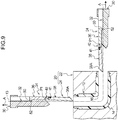
Fig. 9 is a perspective view illustrating a mold employed for molding a pipe body provided with a bent pipe structure according to the first exemplary embodiment of the present invention. -
Fig. 10A is a figure illustrating a table of analysis results for a pipe body provided with a bent pipe structure according to the first exemplary embodiment of the present invention. -
Fig. 10B is a figure illustrating a table of analysis results for a pipe body according to a comparative example. -
Fig. 11A is a figure illustrating a table of analysis results for a pipe body provided with a bent pipe structure according to the first exemplary embodiment of the present invention. -
Fig. 11B is a figure illustrating a table of analysis results for a pipe body according to a comparative example. -
Fig. 12A is a figure illustrating a table of analysis results for a pipe body provided with a bent pipe structure according to the first exemplary embodiment of the present invention. -
Fig. 12B is a figure illustrating a table of analysis results for a pipe body according to a comparative example. -
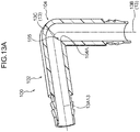
Fig. 13A is a perspective cross-section view illustrating a pipe body provided with a bent pipe structure according to a comparative example to a bent pipe structure according to the first exemplary embodiment of the present invention. -
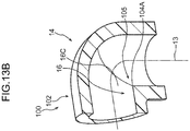
Fig. 13B is an enlarged perspective cross-section view illustrating a pipe body provided with a bent pipe structure according to a comparative example to a bent pipe structure according to the first exemplary embodiment of the present invention. -
Fig. 14 is a side cross-section illustrating a pipe body provided with a bent pipe structure according to a comparative example to a bent pipe structure according to the first exemplary embodiment of the present invention. -
Fig. 15 is a cross-section illustrating a pipe body provided with a bent pipe structure according to a comparative example to a bent pipe structure according to the first exemplary embodiment of the present invention. -
Fig. 16A is a perspective cross-section view illustrating a pipe body provided with a bent pipe structure according to a second exemplary embodiment of the present invention. -
Fig. 16B is an enlarged perspective cross-section view illustrating a pipe body provided with a bent pipe structure according to the second exemplary embodiment of the present invention. -
Fig. 17 is a side cross-section illustrating a pipe body provided with a bent pipe structure according to a second exemplary embodiment of the present invention. -
Fig. 18 is a cross-section illustrating a bend of a pipe body provided with a bent pipe structure according to a second exemplary embodiment of the present invention. -
Fig. 19A is a figure illustrating a table of analysis results for a pipe body provided with a bent pipe structure according to the second exemplary embodiment of the present invention. -
Fig. 19B is a figure illustrating a table of analysis results for a pipe body according to a comparative example. -
Fig. 20A is a figure illustrating a table of analysis results for a pipe body provided with a bent pipe structure according to the second exemplary embodiment of the present invention. -
Fig. 20B is a figure illustrating a table of analysis results for a pipe body according to a comparative example. -
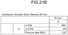
Fig. 21A is a figure illustrating a table of analysis results for a pipe body provided with a bent pipe structure according to the second exemplary embodiment of the present invention. -
Fig. 21B is a figure illustrating analysis results for a pipe body according to a comparative example. - Explanation follows regarding an example of a bent pipe structure according to a first exemplary embodiment of the present invention, with reference to
Fig. 1A to Fig. 15 . - As illustrated in
Fig. 4 , a flow path with a circular cross-section is formed running along anaxial line 13 of apipe body 12 of abent pipe 10, and thepipe body 12 includes abend 14 at a part where theaxial line 13 is bent at substantially a right angle. Namely, theaxial line 13 is configured from a firststraight line portion 13A extending in a straight line shape at an entrance side of thepipe body 12, a secondstraight line portion 13B extending in a straight line shape at an exit of thepipe body 12, and acircular arc portion 13C that has a circular arc shape and couples an end portion of the firststraight line portion 13A and the secondstraight line portion 13B together. - Both
end portions 12B of thepipe body 12 are open, and, for example, both endportions 12B are respectively coupled to ahose 18. - As illustrated in
Fig. 1A ,Fig. 1B , andFig. 2 , acurved portion 14A at an innercircumferential face 15 on a bend direction inside of thebend 14 is configured with a circular arc shape. By configuring thecurved portion 14A with a circular arc shape, arecess 16, serving as an example of a cross-sectional area enlargement portion that enlarges the cross-sectional area of the flow path of thepipe body 12 running along the direction of theaxial line 13, is formed in the innercircumferential face 15 on the bend direction inside of thebend 14. - The
recess 16 enlarges the cross-sectional area of the flow path at thebend 14, such that when a fluid such as a liquid passes through the inside of the bend 14 (namely, a fluid flowing along arrow W inFig. 1A ), an increase in pressure drop in the fluid can be suppressed at therecess 16. Note that the bend direction inside is the side where thepipe body 12 is constricted along the bend direction (namely, the direction of the bend). - Explanation follows regarding the
recess 16 of thepipe body 12 in comparison to apipe body 102 of abent pipe 100 of a comparative example (namely, a conventional form). - First, explanation is given regarding the
pipe body 102 of thebent pipe 100 according to the comparative example. - As illustrated in
Fig. 13A ,Fig. 13B , andFig. 14 , in thepipe body 102 of thebent pipe 100 according to the comparative example, acurved portion 104A at an innercircumferential face 105 on a bend direction inside of abend 104 is configured by a sharp corner (namely, a state not configured by a circular arc shape). Thus, a recess that enlarges the cross-sectional area of a flow path of thepipe body 102 is not formed in the innercircumferential face 105 on the bend direction inside of thebend 104 of thebent pipe 100. - A cross-section of the
bend 104, sectioned along thebend 104 as viewed along an orthogonal direction that is orthogonal to the direction of the axial line 13 (a direction orthogonal to the firststraight line portion 13A and the secondstraight line portion 13B, and the direction into the page inFig. 2 andFig. 14 ; referred to below as an "axis orthogonal direction") (a cross-section taken along line D-D inFig. 14 ), has a shape as illustrated inFig. 15 . As illustrated inFig. 15 , the flow path in the cross-section of thebend 104 has an elliptical shape centered about theaxial line 13. In other words, the flow path has an elliptical shape centered about theaxial line 13 when viewing the flow path of thebend 104 along the direction of theaxial line 13. - In contrast thereto, as illustrated in
Fig. 2 , thecurved portion 14A at the inside of thebend 14 in thepipe body 12 of thebent pipe 10 has a curved arc shape as described above. The radius R illustrated inFig. 2 denotes a curvature R of thecurved portion 14A. - A cross-section of the
bend 14, sectioned as viewed along the axis orthogonal direction (a cross-section along line J-J inFig. 2 ), has a shape as illustrated inFig. 3 . As illustrated inFig. 3 , thebend 14 is formed with therecess 16, described above, so as to enlarge the flow path with respect to the elliptical shape centered about theaxial line 13. - Specifically, the
recess 16 is configured from a pair ofside face portions 16B that face each other along the axis orthogonal direction (the arrow Y direction inFig. 3 ), and abottom face portion 16A that couples respective lower ends of theside face portions 16B together. Therecess 16 has a curved shape that protrudes toward the outer circumferential face of thepipe body 12. In other words, when viewing the flow path of thebend 14 along the direction of theaxial line 13, therecess 16 has a curved shape that protrudes toward the outer circumferential face of thepipe body 12. In the present exemplary embodiment, when viewing the flow path of thebend 14 along theaxial line 13 direction, the pair ofside face portions 16B are configured with circular arc shapes having shapes that are symmetrical to each other, and thebottom face portion 16A is configured with a circular arc shape that smoothly links the pair ofside face portions 16B together. The dimension H illustrated inFig. 3 denotes the width of the recess 16 (width H). -
Fig. 1A ,Fig. 1B ,Fig. 2 , andFig. 3 illustrate the shape of thepipe body 102 according to the comparative example with a double-dotted dashed line. Accordingly, in thebend 14 of thepipe body 12, it is apparent that due to forming therecess 16 in thebend 14, the cross-sectional area of the flow path of thebend 14 is enlarged compared to that of thebend 104 of thepipe body 102 according to the comparative example. - Note that as illustrated in
Fig. 2 , the curvature R described above has a curvature that gradually changes so as to become 0 (mm) atend portions 16C of therecess 16 along the axis orthogonal direction. - Explanation follows regarding a mold employed in molding the
pipe body 12. - As illustrated in
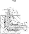
Fig. 7 , a bentpipe molding mold 20 of the present exemplary embodiment includes anouter mold 22 and aninner mold 24. Theouter mold 22 has a two-piece split mold structure, and forms the outer circumferential face of thepipe body 12, which is made of synthetic resin and molded by injection molding. Theinner mold 24 molds the innercircumferential face 15 of thepipe body 12. Theinner mold 24 includes a pair ofprimary cores 30 having the same shape as each other, and a pair of hinged cores 34 (secondary cores) having the same shape as each other and serving as secondary cores. Eachprimary core 30 and each hingedcore 34 has an elongated shape running along the direction of theaxial line 13 of thepipe body 12. At a central portion of thebend 14 along the direction of theaxial line 13, the respectiveprimary cores 30 and the respective hingedcores 34 can be separated from each other or combined with each other along the direction of theaxial line 13 by being pulled apart from each other or being moved closer together along the direction of theaxial line 13 of thepipe body 12. - As illustrated in
Fig. 5 andFig. 6 , agroove 32 is formed in eachprimary core 30 along the direction of theaxial line 13 of thepipe body 12 at a location corresponding to the innercircumferential face 15 on the bend direction inside of the bend 14 (seeFig. 1 ). Aleading end portion 30A of eachprimary core 30 accordingly has a shape that does not engage with an undercut portion of therecess 16 in the innercircumferential face 15 on the bend direction inside of thebend 14 of thepipe body 12. - Each hinged
core 34 is inserted into therespective grooves 32 of theprimary cores 30 so as to be capable of sliding relative to theprimary core 30 along the direction of theaxial line 13 of thepipe body 12. Note that the innercircumferential face 15 of thepipe body 12 is molded by curved molding faces 30B of theprimary cores 30 and curved molding faces 34A of the hingedcores 34.Abase portion 36 at one length direction side of each hingedcore 34 and a swingingportion 38 at another length direction side of each hingedcore 34 are coupled together by ahinge 40. - As illustrated in
Fig. 7 , recesses of therespective base portions 36, which are formed with semicircular shapes as viewed from a side orthogonal to the direction of theaxial line 13, and protrusions of theswing portions 38, engage with each other at thehinges 40 of the hingedcores 34. Each swingingportions 38 swings with respect to thebase portion 36 about an axis PI of therespective hinge 40, in a direction approaching the axial line 13 (arrow B direction inFig. 5 ) and in a direction going away from the axial line 13 (direction opposite to that of arrow B inFig. 5 ). Moreover, each hinge 40 has a built-incoil spring 41, serving as a biasing means, and the respective swingingportion 38 swing with respect to thebase portion 36 in the direction approaching the axial line 13 (the arrow B direction inFig. 5 ) due to the biasing force of thecoil spring 41. Namely, each swingingportion 38 is biased in the arrow B direction inFig. 5 by therespective hinge 40, and is pressed against the bottom of thegroove 32. - Leading ends 38A of the swinging
portions 38 of the respective hingedcores 34 correspond to the undercut portion of therecess 16 that is to be formed in the innercircumferential face 15 on the bend direction inside of thebend 14 of thepipe body 12, and have curved shapes that engage with therecess 16. - Namely, in the molding position illustrated in
Fig. 7 , the leading ends 38A of the swingingportions 38 of the pair of hingedcores 34 are positioned so as to form therecess 16, this being in the innercircumferential face 15 on the bend direction inside of thebend 14 of thepipe body 12. The swingingportions 38 of the pair of hingedcores 34 are housed in therespective groove 32 of eachprimary core 30, these being in the molding position. - As illustrated in
Fig. 8 , when the pair ofprimary cores 30 are separated from each other and respectively move from the molding position along a retracted position direction (the arrow A direction inFig. 8 ), the swingingportion 38 of each hingedcore 34 is swung in the arrow B direction inFig. 8 by therespective hinge 40. Namely, the swingingportion 38 of each hingedcore 34 swings from its molding position illustrated inFig. 7 , toward the space left at the molding position of the respectiveprimary core 30 by theprimary core 30 moving away (to a swung position of the swinging portion 38), as illustrated inFig. 8 . - As illustrated in
Fig. 9 , when the pair ofprimary cores 30 respectively move further along the retracted position direction (the arrow A direction inFig. 9 ),engagement portions 50 formed in the leading ends of thegrooves 32 of the pair ofprimary cores 30 respectively engage withprotrusion 52 formed on thebase portion 36 of each hingedcore 34. The respective hingedcores 34 thereby move together with the pair ofprimary cores 30 in the arrow A direction inFig. 9 , and theinner mold 24 is separated from thepipe body 12. - In order to mold the
pipe body 12 using the bentpipe molding mold 20 of the present exemplary embodiment, first, a synthetic resin is injected into the space formed between theouter mold 22 and theinner mold 24, and thepipe body 12 of the bent pipe that includes therecess 16 is molded. Then, theouter mold 22 is removed and theinner mold 24 is separated from thepipe body 12. - When this is performed, the pair of
primary cores 30 are separated by each being pulled, with respect to each of the pair of hingedcores 34, from the molding position illustrated inFig. 7 , along thegrooves 32 in a pull-out direction running along the axial line 13 (the arrow A direction inFig. 8 ). After the pair ofprimary cores 30 have been separated and moved in the direction toward the retracted position from the molding position, the swingingportion 38 of each hingedcore 34 swings through therespective hinge 40 toward the space at the molding position of the respectiveprimary core 30 arising from moving theprimary cores 30. The swingingportion 38 of each hingedcore 34 thereby adopts the swung position illustrated inFig. 8 . Next, as illustrated inFig. 9 , when the pair ofprimary cores 30 are moved even further along the retracted position direction (the arrow A direction inFig. 9 ), theengagement portion 50 formed in the leading end of eachgroove 32 of the pair ofprimary cores 30 engages with theprotrusion 52 formed in thebase portion 36 of the respective hingedcore 34. The respective hingedcores 34, together with the pair ofprimary cores 30, then move along the arrow A direction inFig. 9 , and theinner mold 24 can be easily removed from thepipe body 12. - Next, explanation follows regarding an evaluation method, evaluation specifications, evaluation items, and evaluation results that were evaluated by analyzing the
pipe body 12 according to the first exemplary embodiment and thepipe body 102 according to the comparative example. -
- Analysis was performed using ANSYS Fluent from ANSYS Japan K.K.
- The flow rate of fluid flowing through the inside of the pipe body was set to 50 L/min.
- The fluid (medium) density of fluid flowing through the inside of the pipe body was set to 1.046 kg/m3 and the fluid (medium) viscosity was set to 0.00191 Pa·s, so as to configure the fluid as cooling water with a 30% concentration (Long Life Coolant: LLC).
-
- (1) The following specifications were used for the present exemplary embodiment.
- A
pipe body 12 having an inner diameter of 6 mm, arecess 16 having a width H of 1 mm, and acurved portion 14A having a curvature R of 1 mm. - A
pipe body 12 having an inner diameter of 6 mm, arecess 16 having a width H of 2 mm, and acurved portion 14A having a curvature R of 1 mm. - A
pipe body 12 having an inner diameter of 6 mm, arecess 16 having a width H of 3 mm, and acurved portion 14A having a curvature R of 1 mm or 2 mm. - A
pipe body 12 having an inner diameter of 6 mm, arecess 16 having a width H of 4 mm, and acurved portion 14A having a curvature R of 1 mm. - A
pipe body 12 having an inner diameter of 16 mm, arecess 16 having a width H of 5 mm, and acurved portion 14A having a curvature R of 3 mm or 5 mm. - A
pipe body 12 having an inner diameter of 16 mm, arecess 16 having a width H of 7 mm, and acurved portion 14A having a curvature R of 3 mm or 5 mm. - A
pipe body 12 having an inner diameter of 16 mm, arecess 16 having a width H of 9 mm, and acurved portion 14A having a curvature R of 3 mm, 5 mm, or 7 mm. - A
pipe body 12 having an inner diameter of 16 mm, arecess 16 having a width H of 11 mm, and acurved portion 14A having a curvature R of 3 mm, 5 mm, or 7 mm. - A
pipe body 12 having an inner diameter of 16 mm, arecess 16 having a width H of 13 mm, and acurved portion 14A having a curvature R of 3 mm or 5 mm. - A
pipe body 12 having an inner diameter of 16 mm, arecess 16 having a width H of 15 mm, and acurved portion 14A having a curvature R of 3 mm. - A
pipe body 12 having an inner diameter of 23 mm, arecess 16 having a width H of 8 mm, and acurved portion 14A having a curvature R of 7 mm. - A
pipe body 12 having an inner diameter of 23 mm, arecess 16 having a width H of 10 mm, and acurved portion 14A having a curvature R of 7 mm. - A
pipe body 12 having an inner diameter of 23 mm, arecess 16 having a width H of 12 mm, and acurved portion 14A having a curvature R of 7 mm. - A
pipe body 12 having an inner diameter of 23 mm, arecess 16 having a width H of 14 mm, and acurved portion 14A having a curvature R of 7 mm. - A
pipe body 12 having an inner diameter of 23 mm, arecess 16 having a width H of 16 mm, and acurved portion 14A having a curvature R of 7 mm or 10 mm. - A
pipe body 12 having an inner diameter of 23 mm, arecess 16 having a width H of 18 mm, and acurved portion 14A having a curvature R of 7 mm. - A
pipe body 12 having an inner diameter of 23 mm, arecess 16 having a width H of 20 mm, and acurved portion 14A having a curvature R of 7 mm.
- A
- (2) The following specifications were used for the comparative example.
- A
pipe body 102 having an inner diameter of 6 mm, and acurved portion 104A having a curvature R of 0 mm (a sharp corner). - A
pipe body 102 having an inner diameter of 16 mm, and acurved portion 104A having a curvature R of 0 mm (a sharp corner). - A
pipe body 102 having an inner diameter of 23 mm, and acurved portion 104A having a curvature R of 0 mm (a sharp corner).
- A
-
- (1) The inflow pressure when fluid flows into a pipe body 12 (in (Pa)), and the outflow pressure when fluid flows out from the pipe body 12 (out (Pa)), were derived.
- (2) The difference between the inflow pressure and the outflow pressure was derived as the pressure drop (pressure drop (kPa)).
- (3) The proportional reduction of pressure drop (pressure drop (%)) in the
pipe body 12 according to the present exemplary embodiment, with respect to the pressure drop in apipe body 102 according to the comparative example of the same internal diameter, was derived. -
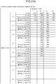
- (1) Evaluation results of the present first exemplary embodiment for a
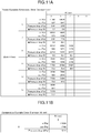
pipe body 12 configured with an inner diameter of 6 mm are listed in the table inFig. 10A . Evaluation results of the comparative example for apipe body 102 configured with an inner diameter of 6 mm are listed in the table inFig. 10B . - (2) Evaluation results of the present first exemplary embodiment for a
pipe body 12 configured with an inner diameter of 16 mm are listed in the table inFig. 11A . Evaluation results of the comparative example for apipe body 102 configured with an inner diameter of 16 mm are listed in the table inFig. 11B . - (3) Evaluation results of the present first exemplary embodiment for a
pipe body 12 configured with an inner diameter of 23 mm are listed in the table inFig. 12A . Evaluation results of the comparative example for apipe body 102 configured with an inner diameter of 23 mm are listed in the table inFig. 12B . - As is apparent from the evaluation results above, the proportional reductions in pressure drop in the
pipe body 12 are all positive numerical values. Namely, due to forming therecess 16 configured with a curvature R and a width H as described in the evaluation specifications above in thepipe body 12, an increase in pressure drop in fluid flowing through thebend 14 can be suppressed compared to in thepipe body 102 according to the comparative example. - Next, explanation follows regarding an example of a bent pipe structure according to a second exemplary embodiment of the present invention, with reference to
Fig. 16A to Fig. 21B . Note that members that are similar to those of the first exemplary embodiment are appended with the same reference numerals, explanation thereof is omitted, and explanation is mainly given regarding portions that differ from those of the first exemplary embodiment. - As illustrated in
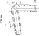
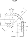
Fig. 16A ,Fig. 16B , andFig. 17 , acurved portion 64A at an innercircumferential face 65 at a bend direction inside of abend 64 in apipe body 62 of abent pipe 60 according to the second exemplary embodiment is configured with a circular arc shape. By configuring thecurved portion 64A with a circular arc shape, arecess 66, serving as an example of a cross-sectional area enlargement portion that enlarges the cross-sectional area of the flow path of apipe body 62 running along the direction of theaxial line 13, is formed in the innercircumferential face 65 on the bend direction inside of thebend 64. Therecess 66 is configured from a pair ofside face portions 66B that face each other along the axis orthogonal direction (the direction into the page inFig. 17 ), and abottom face portion 66A that couples respective lower ends of theside face portions 66B together (seeFig. 18 ). Theside face portions 66B have flat face shapes, and thebottom face portion 66A has a curved face shape. The radius R illustrated inFig. 17 denotes a curvature R of thecurved portion 64A. - A cross-section of the
bend 64, sectioned as viewed along the axis orthogonal direction (a cross-section taken along line K-K inFig. 17 ), has a shape as illustrated inFig. 18 . By forming therecess 66, the flow path is enlarged with respect to an elliptical shape centered about theaxial line 13. - Specifically, the
recess 66 is configured from the pair ofside face portions 66B and thebottom face portion 66A described above. In the cross-section illustrated inFig. 18 , theside face portions 66B are formed in straight lines, and thebottom face portion 66A is formed in a curved line shape that protrudes toward the outer circumferential side of thepipe body 62. In other words, when viewing the flow path of thebend 64 along the direction of theaxial line 13, theside face portions 66B are formed in straight lines, and thebottom face portion 66A is formed in a curved shape that protrudes toward the outer circumferential side of thepipe body 62. The dimension H illustrated inFig. 18 denotes the width of the recess 66 (width H). - Next, explanation follows regarding evaluation specifications and evaluation results that were evaluated by analyzing the
pipe body 62 according to the second exemplary embodiment and thepipe body 102 according to the comparative example. -
- (1) The following specifications were used for the present exemplary embodiment.
- A
pipe body 62 having an inner diameter of 6 mm, arecess 66 having a width H of 1 mm, and abend portion 64A having a curvature R of 2 mm or 3 mm. - A
pipe body 62 having an inner diameter of 6 mm, arecess 66 having a width H of 2 mm, and abend portion 64A having a curvature R of 2 mm. - A
pipe body 62 having an inner diameter of 16 mm, arecess 66 having a width H of 5 mm, and abend portion 64A having a curvature R of 7 mm, 9 mm, or 11 mm. - A
pipe body 62 having an inner diameter of 16 mm, arecess 66 having a width H of 7 mm, and abend portion 64A having a curvature R of 7 mm or 9 mm. - A
pipe body 62 having an inner diameter of 23 mm, arecess 66 having a width H of 6 mm, and abend portion 64A having a curvature R of 7 mm, 10 mm, 13 mm, or 16 mm. - A
pipe body 62 having an inner diameter of 23 mm, arecess 66 having a width H of 8 mm, and abend portion 64A having a curvature R of 10 mm or 13 mm. - A
pipe body 62 having an inner diameter of 23 mm, arecess 66 having a width H of 10 mm, and abend portion 64A having a curvature R of 10 mm or 13 mm. - A
pipe body 62 having an inner diameter of 23 mm, arecess 66 having a width H of 12 mm, and abend portion 64A having a curvature R of 10 mm or 13 mm. - A
pipe body 62 having an inner diameter of 23 mm, arecess 66 having a width H of 14 mm, and abend portion 64A having a curvature R of 10 mm.
- A
- (2) The following specifications were used for the comparative example (these being similar to those of the first exemplary embodiment)
- A
pipe body 102 having an inner diameter of 6 mm, and acurved portion 104A having a curvature R of 0 mm (a sharp corner). - A
pipe body 102 having an inner diameter of 16 mm, and acurved portion 104A having a curvature R of 0 mm (a sharp corner). - A
pipe body 102 having an inner diameter of 23 mm, and acurved portion 104A having a curvature R of 0 mm (a sharp corner).
- A
-
- (1) Evaluation results of the present second exemplary embodiment for a
pipe body 62 configured with an inner diameter of 6 mm are listed in the table inFig. 19A . Evaluation results of the comparative example for apipe body 102 configured with an inner diameter of 6 mm are listed in the table inFig. 19B . - (2) Evaluation results of the present second exemplary embodiment for a
pipe body 62 configured with an inner diameter of 16 mm are listed in the table inFig. 20A . Evaluation results of the comparative example for apipe body 102 configured with an inner diameter of 16 mm are listed in the table inFig. 20B . - (3) Evaluation results of the present second exemplary embodiment for a
pipe body 62 configured with an inner diameter of 23 mm are listed in the table inFig. 21A . Evaluation results of the comparative example for apipe body 102 configured with an inner diameter of 23 mm are listed in the table inFig. 21B . - As is apparent from the above evaluation results, the proportional reductions in pressure drop in the
pipe body 62 are all positive numerical values. Namely, due to forming thepipe body 62 with therecess 66 configured with a curvature R and a width H as described in the evaluation specifications, an increase in pressure drop in fluid flowing through thebend 64 can be suppressed compared to in thepipe body 102 according to the comparative example. - Note that although detailed explanation has been given regarding specific exemplary embodiments of the present invention, the present invention is not limited to these exemplary embodiments, and it would be obvious to a person having ordinary skill in the art that various other exemplary embodiments are possible within the scope of the present invention. For example, the mold configuration explained in the above exemplary embodiments is merely exemplary, and the pipe body may be molded using nested molds or the like.
Claims (2)
- A bent pipe (10) structure comprising:a pipe body (12) that includes a bend (14), anda cross-sectional area enlargement portion (16) that is formed by configuring a curved portion (14A) with a circular arc shape at an inner circumferential face (15) on a bend direction inside of the bend (14) so as to enlarge a cross-sectional area of a flow path of the pipe body (12); whereinthe cross-sectional area enlargement portion (16) includes a pair of side face portions (16B) that face each other along an orthogonal direction orthogonal to an axial line (13) of the pipe body (12), and a bottom face portion (16A) that couples lower ends of the side face portions (16B) together, and, when viewed along the direction of the axial line (13), the cross-sectional area enlargement portion (16) is formed in a curved shape that protrudes toward an outer circumferential side of the pipe body (12); characterised in thatthe bent pipe (10) structure satisfies one of the following relationships, wherein P (mm) denotes the inner diameter of the pipe body (12), H (mm) denotes the separation distance between the pair of side face portions (16B) measured between end portions (16C) of the pair of side face portions (16B) along the orthogonal direction orthogonal to the axis line (13), as viewed along the direction of the axial line (13), and R (mm) denotes the radius of the curved portion (14A):R = 1 when P = 6 and H = 1,R = 1 when P = 6 and H = 2,R = 1 or greater and R = 2 or less when P = 6 and H = 3,R = 1 when P = 6 and H = 4,R = 3 or greater and R = 5 or less when P = 16 and H = 5,R = 3 or greater and R = 5 or less when P = 16 and H = 7,R = 3 or greater and R = 7 or less when P = 16 and H = 9,R = 3 or greater and R = 7 or less when P = 16 and H = 11,R = 3 or greater and R = 5 or less when P = 16 and H = 13,R = 3 when P = 16 and H = 15,R = 7 when P = 23 and H = 8,R = 7 when P = 23 and H = 10,R = 7 when P = 23 and H = 12,R = 7 when P = 23 and H = 14,R = 7 or greater and R = 10 or less when P = 23 and H = 16,R = 7 when P = 23 and H = 18, andR = 7 when P = 23 and H = 20.
- A bent pipe (60) structure comprising:a pipe body (62) that includes a bend (64), anda cross-sectional area enlargement portion (66) that is formed by configuring a curved portion (64A) with a circular arc shape at an inner circumferential face (65) on a bend direction inside of the bend (64) so as to enlarge a cross-sectional area of a flow path of the pipe body (62); whereinthe cross-sectional area enlargement portion (66) includes a pair of side face portions (66B) that face each other along an orthogonal direction orthogonal to an axial line (13) of the pipe body (62), and a bottom face portion (66A) that couples lower ends of the side face portions (66B) together, and, when viewed along the direction of the axial line (13), the side face portions (66B) are formed with straight lines; the bent pipe structure is characterised in thatthe bottom face portion (66B) is formed in a curved shape that protrudes toward an outer circumferential side of the pipe body (62); andthe bent pipe (60) structure satisfies one of the following relationships, wherein P (mm) denotes the inner diameter of the pipe body (62), H (mm) denotes the separation distance between the pair of side face portions (66B), as viewed along the direction of the axial line (13), and R (mm) denotes the radius of the curved portion (64A):R = 2 or greater and R = 3 or less when P = 6 and H = 1,R = 2 when P = 6 and H = 2,R = 7 or greater and R = 11 or less when P = 16 and H = 5,R = 7 or greater and R = 9 or less when P = 16 and H = 7,R = 7 or greater and R = 16 or less when P = 23 and H = 6,R = 10 or greater and R = 13 or less when P = 23 and H = 8,R = 10 or greater and R = 13 or less when P = 23 and H = 10,R = 10 or greater and R = 13 or less when P = 23 and H = 12, andR = 10 when P = 23 and H = 14.
Applications Claiming Priority (2)
| Application Number | Priority Date | Filing Date | Title |
|---|---|---|---|
| JP2014055591A JP6152064B2 (en) | 2014-03-18 | 2014-03-18 | Curved pipe structure |
| PCT/JP2015/055673 WO2015141435A1 (en) | 2014-03-18 | 2015-02-26 | Bent pipe structure |
Publications (3)
| Publication Number | Publication Date |
|---|---|
| EP3121502A1 EP3121502A1 (en) | 2017-01-25 |
| EP3121502A4 EP3121502A4 (en) | 2017-12-27 |
| EP3121502B1 true EP3121502B1 (en) | 2019-10-30 |
Family
ID=54144411
Family Applications (1)
| Application Number | Title | Priority Date | Filing Date |
|---|---|---|---|
| EP15764657.1A Active EP3121502B1 (en) | 2014-03-18 | 2015-02-26 | Bent pipe structure |
Country Status (6)
| Country | Link |
|---|---|
| US (1) | US10400931B2 (en) |
| EP (1) | EP3121502B1 (en) |
| JP (1) | JP6152064B2 (en) |
| KR (1) | KR101833661B1 (en) |
| CN (1) | CN106104134B (en) |
| WO (1) | WO2015141435A1 (en) |
Families Citing this family (5)
| Publication number | Priority date | Publication date | Assignee | Title |
|---|---|---|---|---|
| JP7019988B2 (en) * | 2017-07-27 | 2022-02-16 | 株式会社オンダ製作所 | Resin elbow fitting |
| JP6939194B2 (en) * | 2017-07-27 | 2021-09-22 | 株式会社オンダ製作所 | Resin elbow fitting |
| CA3090441A1 (en) * | 2018-02-06 | 2019-08-15 | Uponor Innovation Ab | Mold assembly for injection molding of a plastic pipe fitting and injection molded pipe fitting made of plastics |
| JP7303991B2 (en) * | 2018-05-28 | 2023-07-06 | 株式会社オンダ製作所 | Resin joint |
| DE102021124552A1 (en) | 2021-09-22 | 2023-03-23 | Norma Germany Gmbh | Flow-optimized line connector and line connector arrangement |
Family Cites Families (21)
| Publication number | Priority date | Publication date | Assignee | Title |
|---|---|---|---|---|
| US2303949A (en) * | 1940-01-13 | 1942-12-01 | Carl H Nordell | Conduit bend |
| JPS61215890A (en) * | 1985-03-20 | 1986-09-25 | 堀井 清之 | Bent pipe |
| JPH0353119Y2 (en) * | 1985-07-10 | 1991-11-19 | ||
| DE3704827A1 (en) * | 1987-02-16 | 1988-08-25 | Marquet & Cie Noel | Universal insulating half-shells which are bent at right angles and are intended for right-angled pipe bends with different bend radii and bend ends |
| US5054819A (en) * | 1990-02-16 | 1991-10-08 | Victaulic Company Of America | Plumbing elbows or bends |
| JP2844857B2 (en) | 1990-06-21 | 1999-01-13 | ソニー株式会社 | Manufacturing equipment for hybrid integrated circuits |
| US5230369A (en) * | 1990-12-24 | 1993-07-27 | United Technologies Corporation | Structure to reduce turning losses in angled conduit |
| JPH04362394A (en) * | 1991-06-07 | 1992-12-15 | Mitsui Constr Co Ltd | Vent pipe |
| JP2000002371A (en) | 1998-06-15 | 2000-01-07 | Hitachi Ltd | Elbow/bend pipe, manufacture thereof, and manufacturing device therefor |
| CN1277664A (en) * | 1998-09-21 | 2000-12-20 | 东林产业株式会社 | Anti-abrasion pipe fittings for high-speed particle-laden flow |
| US7153125B2 (en) * | 2000-01-19 | 2006-12-26 | Rain Bird Corporation | Molded plastic elbow |
| JP2001219453A (en) | 2000-02-07 | 2001-08-14 | Sekisui Chem Co Ltd | Method for molding cylindrical molded article and injection mold |
| JP3893581B2 (en) * | 2000-05-25 | 2007-03-14 | 愛知機械工業株式会社 | Manufacturing method of pipe flange |
| JP2003254490A (en) * | 2002-03-01 | 2003-09-10 | Toyota Motor Corp | Fluid passage having bend part |
| JP2004211873A (en) | 2003-01-08 | 2004-07-29 | Inax Corp | Hose |
| JP4362394B2 (en) * | 2003-03-28 | 2009-11-11 | Ntn株式会社 | Compressor bearing |
| DE202007012584U1 (en) * | 2007-04-02 | 2008-08-14 | Voss Automotive Gmbh | Connecting element for media lines and injection molding device for producing the connection element |
| ES2861203T3 (en) * | 2009-01-28 | 2021-10-06 | Scott Doig | Wear resistant mud pipe fitting |
| RU2533569C2 (en) * | 2010-06-28 | 2014-11-20 | Нода Канагата Ко., Лтд. | Angular pipe made by cutting and method of cutting said pipe |
| KR20140036965A (en) * | 2012-09-18 | 2014-03-26 | 가부시키가이샤 니프코 | Curved tube structure and mold for molding curved tube |
| JP6391987B2 (en) * | 2014-05-16 | 2018-09-19 | 山下ゴム株式会社 | Curved pipe and its manufacturing method |
-
2014
- 2014-03-18 JP JP2014055591A patent/JP6152064B2/en active Active
-
2015
- 2015-02-26 CN CN201580012501.4A patent/CN106104134B/en active Active
- 2015-02-26 US US15/126,774 patent/US10400931B2/en active Active
- 2015-02-26 EP EP15764657.1A patent/EP3121502B1/en active Active
- 2015-02-26 WO PCT/JP2015/055673 patent/WO2015141435A1/en active Application Filing
- 2015-02-26 KR KR1020167025898A patent/KR101833661B1/en active IP Right Grant
Non-Patent Citations (1)
| Title |
|---|
| None * |
Also Published As
| Publication number | Publication date |
|---|---|
| JP6152064B2 (en) | 2017-06-21 |
| KR20160123381A (en) | 2016-10-25 |
| JP2015178844A (en) | 2015-10-08 |
| CN106104134B (en) | 2017-11-17 |
| KR101833661B1 (en) | 2018-02-28 |
| WO2015141435A1 (en) | 2015-09-24 |
| EP3121502A1 (en) | 2017-01-25 |
| CN106104134A (en) | 2016-11-09 |
| US20180128408A1 (en) | 2018-05-10 |
| US10400931B2 (en) | 2019-09-03 |
| EP3121502A4 (en) | 2017-12-27 |
Similar Documents
| Publication | Publication Date | Title |
|---|---|---|
| EP3121502B1 (en) | Bent pipe structure | |
| JP6388620B2 (en) | Curved pipe structure | |
| EP3081362B1 (en) | Mesh filter | |
| JP2023126826A (en) | Resin elbow joint | |
| KR101711773B1 (en) | Container with synthetic resin window, and preform | |
| EP3632648A1 (en) | Injection molding die, resin member, and method for producing resin article | |
| EP3632647A1 (en) | Injection molding die, resin member, and method for producing resin article | |
| EP3632649A1 (en) | Injection molding die, resin member, and method for producing resin article | |
| JP2016074029A (en) | Tubular member | |
| JP7107919B2 (en) | Valve housing, valve and method for manufacturing valve housing | |
| JP6585486B2 (en) | Tire vulcanization mold and pneumatic tire | |
| JP6235366B2 (en) | Coating molding equipment | |
| JP2021030143A (en) | filter | |
| JP2016118215A (en) | Joint | |
| JP2015209236A (en) | Spout plug | |
| TH75505B (en) | Structure of curved pipes and molds for forming curved pipes. | |
| JP2012011686A (en) | Apparatus and method for producing vulcanized rubber molding |
Legal Events
| Date | Code | Title | Description |
|---|---|---|---|
| STAA | Information on the status of an ep patent application or granted ep patent |
Free format text: STATUS: THE INTERNATIONAL PUBLICATION HAS BEEN MADE |
|
| PUAI | Public reference made under article 153(3) epc to a published international application that has entered the european phase |
Free format text: ORIGINAL CODE: 0009012 |
|
| STAA | Information on the status of an ep patent application or granted ep patent |
Free format text: STATUS: REQUEST FOR EXAMINATION WAS MADE |
|
| 17P | Request for examination filed |
Effective date: 20160927 |
|
| AK | Designated contracting states |
Kind code of ref document: A1 Designated state(s): AL AT BE BG CH CY CZ DE DK EE ES FI FR GB GR HR HU IE IS IT LI LT LU LV MC MK MT NL NO PL PT RO RS SE SI SK SM TR |
|
| AX | Request for extension of the european patent |
Extension state: BA ME |
|
| DAX | Request for extension of the european patent (deleted) | ||
| A4 | Supplementary search report drawn up and despatched |
Effective date: 20171129 |
|
| RIC1 | Information provided on ipc code assigned before grant |
Ipc: F16L 43/00 20060101AFI20171123BHEP |
|
| RIC1 | Information provided on ipc code assigned before grant |
Ipc: F16L 43/00 20060101AFI20190425BHEP Ipc: B29C 45/44 20060101ALI20190425BHEP |
|
| GRAP | Despatch of communication of intention to grant a patent |
Free format text: ORIGINAL CODE: EPIDOSNIGR1 |
|
| STAA | Information on the status of an ep patent application or granted ep patent |
Free format text: STATUS: GRANT OF PATENT IS INTENDED |
|
| INTG | Intention to grant announced |
Effective date: 20190617 |
|
| GRAS | Grant fee paid |
Free format text: ORIGINAL CODE: EPIDOSNIGR3 |
|
| GRAA | (expected) grant |
Free format text: ORIGINAL CODE: 0009210 |
|
| STAA | Information on the status of an ep patent application or granted ep patent |
Free format text: STATUS: THE PATENT HAS BEEN GRANTED |
|
| AK | Designated contracting states |
Kind code of ref document: B1 Designated state(s): AL AT BE BG CH CY CZ DE DK EE ES FI FR GB GR HR HU IE IS IT LI LT LU LV MC MK MT NL NO PL PT RO RS SE SI SK SM TR |
|
| REG | Reference to a national code |
Ref country code: GB Ref legal event code: FG4D |
|
| REG | Reference to a national code |
Ref country code: CH Ref legal event code: EP |
|
| REG | Reference to a national code |
Ref country code: AT Ref legal event code: REF Ref document number: 1196523 Country of ref document: AT Kind code of ref document: T Effective date: 20191115 |
|
| REG | Reference to a national code |
Ref country code: DE Ref legal event code: R096 Ref document number: 602015040746 Country of ref document: DE |
|
| REG | Reference to a national code |
Ref country code: IE Ref legal event code: FG4D |
|
| REG | Reference to a national code |
Ref country code: LT Ref legal event code: MG4D |
|
| PG25 | Lapsed in a contracting state [announced via postgrant information from national office to epo] |
Ref country code: SE Free format text: LAPSE BECAUSE OF FAILURE TO SUBMIT A TRANSLATION OF THE DESCRIPTION OR TO PAY THE FEE WITHIN THE PRESCRIBED TIME-LIMIT Effective date: 20191030 Ref country code: LV Free format text: LAPSE BECAUSE OF FAILURE TO SUBMIT A TRANSLATION OF THE DESCRIPTION OR TO PAY THE FEE WITHIN THE PRESCRIBED TIME-LIMIT Effective date: 20191030 Ref country code: NL Free format text: LAPSE BECAUSE OF FAILURE TO SUBMIT A TRANSLATION OF THE DESCRIPTION OR TO PAY THE FEE WITHIN THE PRESCRIBED TIME-LIMIT Effective date: 20191030 Ref country code: PT Free format text: LAPSE BECAUSE OF FAILURE TO SUBMIT A TRANSLATION OF THE DESCRIPTION OR TO PAY THE FEE WITHIN THE PRESCRIBED TIME-LIMIT Effective date: 20200302 Ref country code: FI Free format text: LAPSE BECAUSE OF FAILURE TO SUBMIT A TRANSLATION OF THE DESCRIPTION OR TO PAY THE FEE WITHIN THE PRESCRIBED TIME-LIMIT Effective date: 20191030 Ref country code: BG Free format text: LAPSE BECAUSE OF FAILURE TO SUBMIT A TRANSLATION OF THE DESCRIPTION OR TO PAY THE FEE WITHIN THE PRESCRIBED TIME-LIMIT Effective date: 20200130 Ref country code: GR Free format text: LAPSE BECAUSE OF FAILURE TO SUBMIT A TRANSLATION OF THE DESCRIPTION OR TO PAY THE FEE WITHIN THE PRESCRIBED TIME-LIMIT Effective date: 20200131 Ref country code: NO Free format text: LAPSE BECAUSE OF FAILURE TO SUBMIT A TRANSLATION OF THE DESCRIPTION OR TO PAY THE FEE WITHIN THE PRESCRIBED TIME-LIMIT Effective date: 20200130 Ref country code: PL Free format text: LAPSE BECAUSE OF FAILURE TO SUBMIT A TRANSLATION OF THE DESCRIPTION OR TO PAY THE FEE WITHIN THE PRESCRIBED TIME-LIMIT Effective date: 20191030 Ref country code: LT Free format text: LAPSE BECAUSE OF FAILURE TO SUBMIT A TRANSLATION OF THE DESCRIPTION OR TO PAY THE FEE WITHIN THE PRESCRIBED TIME-LIMIT Effective date: 20191030 |
|
| REG | Reference to a national code |
Ref country code: NL Ref legal event code: MP Effective date: 20191030 |
|
| PG25 | Lapsed in a contracting state [announced via postgrant information from national office to epo] |
Ref country code: RS Free format text: LAPSE BECAUSE OF FAILURE TO SUBMIT A TRANSLATION OF THE DESCRIPTION OR TO PAY THE FEE WITHIN THE PRESCRIBED TIME-LIMIT Effective date: 20191030 Ref country code: HR Free format text: LAPSE BECAUSE OF FAILURE TO SUBMIT A TRANSLATION OF THE DESCRIPTION OR TO PAY THE FEE WITHIN THE PRESCRIBED TIME-LIMIT Effective date: 20191030 Ref country code: IS Free format text: LAPSE BECAUSE OF FAILURE TO SUBMIT A TRANSLATION OF THE DESCRIPTION OR TO PAY THE FEE WITHIN THE PRESCRIBED TIME-LIMIT Effective date: 20200229 |
|
| PG25 | Lapsed in a contracting state [announced via postgrant information from national office to epo] |
Ref country code: AL Free format text: LAPSE BECAUSE OF FAILURE TO SUBMIT A TRANSLATION OF THE DESCRIPTION OR TO PAY THE FEE WITHIN THE PRESCRIBED TIME-LIMIT Effective date: 20191030 |
|
| PG25 | Lapsed in a contracting state [announced via postgrant information from national office to epo] |
Ref country code: CZ Free format text: LAPSE BECAUSE OF FAILURE TO SUBMIT A TRANSLATION OF THE DESCRIPTION OR TO PAY THE FEE WITHIN THE PRESCRIBED TIME-LIMIT Effective date: 20191030 Ref country code: ES Free format text: LAPSE BECAUSE OF FAILURE TO SUBMIT A TRANSLATION OF THE DESCRIPTION OR TO PAY THE FEE WITHIN THE PRESCRIBED TIME-LIMIT Effective date: 20191030 Ref country code: RO Free format text: LAPSE BECAUSE OF FAILURE TO SUBMIT A TRANSLATION OF THE DESCRIPTION OR TO PAY THE FEE WITHIN THE PRESCRIBED TIME-LIMIT Effective date: 20191030 Ref country code: DK Free format text: LAPSE BECAUSE OF FAILURE TO SUBMIT A TRANSLATION OF THE DESCRIPTION OR TO PAY THE FEE WITHIN THE PRESCRIBED TIME-LIMIT Effective date: 20191030 Ref country code: EE Free format text: LAPSE BECAUSE OF FAILURE TO SUBMIT A TRANSLATION OF THE DESCRIPTION OR TO PAY THE FEE WITHIN THE PRESCRIBED TIME-LIMIT Effective date: 20191030 |
|
| REG | Reference to a national code |
Ref country code: DE Ref legal event code: R097 Ref document number: 602015040746 Country of ref document: DE |
|
| REG | Reference to a national code |
Ref country code: AT Ref legal event code: MK05 Ref document number: 1196523 Country of ref document: AT Kind code of ref document: T Effective date: 20191030 |
|
| PG25 | Lapsed in a contracting state [announced via postgrant information from national office to epo] |
Ref country code: IT Free format text: LAPSE BECAUSE OF FAILURE TO SUBMIT A TRANSLATION OF THE DESCRIPTION OR TO PAY THE FEE WITHIN THE PRESCRIBED TIME-LIMIT Effective date: 20191030 Ref country code: SM Free format text: LAPSE BECAUSE OF FAILURE TO SUBMIT A TRANSLATION OF THE DESCRIPTION OR TO PAY THE FEE WITHIN THE PRESCRIBED TIME-LIMIT Effective date: 20191030 Ref country code: SK Free format text: LAPSE BECAUSE OF FAILURE TO SUBMIT A TRANSLATION OF THE DESCRIPTION OR TO PAY THE FEE WITHIN THE PRESCRIBED TIME-LIMIT Effective date: 20191030 |
|
| PLBE | No opposition filed within time limit |
Free format text: ORIGINAL CODE: 0009261 |
|
| STAA | Information on the status of an ep patent application or granted ep patent |
Free format text: STATUS: NO OPPOSITION FILED WITHIN TIME LIMIT |
|
| REG | Reference to a national code |
Ref country code: CH Ref legal event code: PL |
|
| 26N | No opposition filed |
Effective date: 20200731 |
|
| GBPC | Gb: european patent ceased through non-payment of renewal fee |
Effective date: 20200226 |
|
| REG | Reference to a national code |
Ref country code: BE Ref legal event code: MM Effective date: 20200229 |
|
| PG25 | Lapsed in a contracting state [announced via postgrant information from national office to epo] |
Ref country code: MC Free format text: LAPSE BECAUSE OF FAILURE TO SUBMIT A TRANSLATION OF THE DESCRIPTION OR TO PAY THE FEE WITHIN THE PRESCRIBED TIME-LIMIT Effective date: 20191030 Ref country code: LU Free format text: LAPSE BECAUSE OF NON-PAYMENT OF DUE FEES Effective date: 20200226 |
|
| PG25 | Lapsed in a contracting state [announced via postgrant information from national office to epo] |
Ref country code: LI Free format text: LAPSE BECAUSE OF NON-PAYMENT OF DUE FEES Effective date: 20200229 Ref country code: AT Free format text: LAPSE BECAUSE OF FAILURE TO SUBMIT A TRANSLATION OF THE DESCRIPTION OR TO PAY THE FEE WITHIN THE PRESCRIBED TIME-LIMIT Effective date: 20191030 Ref country code: CH Free format text: LAPSE BECAUSE OF NON-PAYMENT OF DUE FEES Effective date: 20200229 Ref country code: SI Free format text: LAPSE BECAUSE OF FAILURE TO SUBMIT A TRANSLATION OF THE DESCRIPTION OR TO PAY THE FEE WITHIN THE PRESCRIBED TIME-LIMIT Effective date: 20191030 |
|
| PG25 | Lapsed in a contracting state [announced via postgrant information from national office to epo] |
Ref country code: GB Free format text: LAPSE BECAUSE OF NON-PAYMENT OF DUE FEES Effective date: 20200226 Ref country code: FR Free format text: LAPSE BECAUSE OF NON-PAYMENT OF DUE FEES Effective date: 20200229 Ref country code: IE Free format text: LAPSE BECAUSE OF NON-PAYMENT OF DUE FEES Effective date: 20200226 |
|
| PG25 | Lapsed in a contracting state [announced via postgrant information from national office to epo] |
Ref country code: BE Free format text: LAPSE BECAUSE OF NON-PAYMENT OF DUE FEES Effective date: 20200229 |
|
| PG25 | Lapsed in a contracting state [announced via postgrant information from national office to epo] |
Ref country code: TR Free format text: LAPSE BECAUSE OF FAILURE TO SUBMIT A TRANSLATION OF THE DESCRIPTION OR TO PAY THE FEE WITHIN THE PRESCRIBED TIME-LIMIT Effective date: 20191030 Ref country code: MT Free format text: LAPSE BECAUSE OF FAILURE TO SUBMIT A TRANSLATION OF THE DESCRIPTION OR TO PAY THE FEE WITHIN THE PRESCRIBED TIME-LIMIT Effective date: 20191030 Ref country code: CY Free format text: LAPSE BECAUSE OF FAILURE TO SUBMIT A TRANSLATION OF THE DESCRIPTION OR TO PAY THE FEE WITHIN THE PRESCRIBED TIME-LIMIT Effective date: 20191030 |
|
| PG25 | Lapsed in a contracting state [announced via postgrant information from national office to epo] |
Ref country code: MK Free format text: LAPSE BECAUSE OF FAILURE TO SUBMIT A TRANSLATION OF THE DESCRIPTION OR TO PAY THE FEE WITHIN THE PRESCRIBED TIME-LIMIT Effective date: 20191030 |
|
| PGFP | Annual fee paid to national office [announced via postgrant information from national office to epo] |
Ref country code: DE Payment date: 20221230 Year of fee payment: 9 |
|
| PGFP | Annual fee paid to national office [announced via postgrant information from national office to epo] |
Ref country code: DE Payment date: 20231229 Year of fee payment: 10 |