EP3121432B1 - Steuerungsvorrichtung und steuerungsverfahren für dieselmotor - Google Patents
Steuerungsvorrichtung und steuerungsverfahren für dieselmotor Download PDFInfo
- Publication number
- EP3121432B1 EP3121432B1 EP14886558.7A EP14886558A EP3121432B1 EP 3121432 B1 EP3121432 B1 EP 3121432B1 EP 14886558 A EP14886558 A EP 14886558A EP 3121432 B1 EP3121432 B1 EP 3121432B1
- Authority
- EP
- European Patent Office
- Prior art keywords
- exhaust
- engine
- gas
- air
- gas flow
- Prior art date
- Legal status (The legal status is an assumption and is not a legal conclusion. Google has not performed a legal analysis and makes no representation as to the accuracy of the status listed.)
- Active
Links
Images


Classifications
-
- F—MECHANICAL ENGINEERING; LIGHTING; HEATING; WEAPONS; BLASTING
- F02—COMBUSTION ENGINES; HOT-GAS OR COMBUSTION-PRODUCT ENGINE PLANTS
- F02D—CONTROLLING COMBUSTION ENGINES
- F02D41/00—Electrical control of supply of combustible mixture or its constituents
- F02D41/0002—Controlling intake air
- F02D41/0007—Controlling intake air for control of turbo-charged or super-charged engines
-
- F—MECHANICAL ENGINEERING; LIGHTING; HEATING; WEAPONS; BLASTING
- F02—COMBUSTION ENGINES; HOT-GAS OR COMBUSTION-PRODUCT ENGINE PLANTS
- F02B—INTERNAL-COMBUSTION PISTON ENGINES; COMBUSTION ENGINES IN GENERAL
- F02B37/00—Engines characterised by provision of pumps driven at least for part of the time by exhaust
- F02B37/12—Control of the pumps
- F02B37/16—Control of the pumps by bypassing charging air
- F02B37/168—Control of the pumps by bypassing charging air into the exhaust conduit
-
- F—MECHANICAL ENGINEERING; LIGHTING; HEATING; WEAPONS; BLASTING
- F02—COMBUSTION ENGINES; HOT-GAS OR COMBUSTION-PRODUCT ENGINE PLANTS
- F02D—CONTROLLING COMBUSTION ENGINES
- F02D21/00—Controlling engines characterised by their being supplied with non-airborne oxygen or other non-fuel gas
- F02D21/06—Controlling engines characterised by their being supplied with non-airborne oxygen or other non-fuel gas peculiar to engines having other non-fuel gas added to combustion air
- F02D21/08—Controlling engines characterised by their being supplied with non-airborne oxygen or other non-fuel gas peculiar to engines having other non-fuel gas added to combustion air the other gas being the exhaust gas of engine
-
- F—MECHANICAL ENGINEERING; LIGHTING; HEATING; WEAPONS; BLASTING
- F02—COMBUSTION ENGINES; HOT-GAS OR COMBUSTION-PRODUCT ENGINE PLANTS
- F02D—CONTROLLING COMBUSTION ENGINES
- F02D23/00—Controlling engines characterised by their being supercharged
-
- F—MECHANICAL ENGINEERING; LIGHTING; HEATING; WEAPONS; BLASTING
- F02—COMBUSTION ENGINES; HOT-GAS OR COMBUSTION-PRODUCT ENGINE PLANTS
- F02D—CONTROLLING COMBUSTION ENGINES
- F02D23/00—Controlling engines characterised by their being supercharged
- F02D23/02—Controlling engines characterised by their being supercharged the engines being of fuel-injection type
-
- F—MECHANICAL ENGINEERING; LIGHTING; HEATING; WEAPONS; BLASTING
- F02—COMBUSTION ENGINES; HOT-GAS OR COMBUSTION-PRODUCT ENGINE PLANTS
- F02D—CONTROLLING COMBUSTION ENGINES
- F02D41/00—Electrical control of supply of combustible mixture or its constituents
- F02D41/0025—Controlling engines characterised by use of non-liquid fuels, pluralities of fuels, or non-fuel substances added to the combustible mixtures
- F02D41/0047—Controlling exhaust gas recirculation [EGR]
- F02D41/0077—Control of the EGR valve or actuator, e.g. duty cycle, closed loop control of position
-
- F—MECHANICAL ENGINEERING; LIGHTING; HEATING; WEAPONS; BLASTING
- F02—COMBUSTION ENGINES; HOT-GAS OR COMBUSTION-PRODUCT ENGINE PLANTS
- F02M—SUPPLYING COMBUSTION ENGINES IN GENERAL WITH COMBUSTIBLE MIXTURES OR CONSTITUENTS THEREOF
- F02M26/00—Engine-pertinent apparatus for adding exhaust gases to combustion-air, main fuel or fuel-air mixture, e.g. by exhaust gas recirculation [EGR] systems
- F02M26/02—EGR systems specially adapted for supercharged engines
- F02M26/04—EGR systems specially adapted for supercharged engines with a single turbocharger
-
- F—MECHANICAL ENGINEERING; LIGHTING; HEATING; WEAPONS; BLASTING
- F02—COMBUSTION ENGINES; HOT-GAS OR COMBUSTION-PRODUCT ENGINE PLANTS
- F02M—SUPPLYING COMBUSTION ENGINES IN GENERAL WITH COMBUSTIBLE MIXTURES OR CONSTITUENTS THEREOF
- F02M26/00—Engine-pertinent apparatus for adding exhaust gases to combustion-air, main fuel or fuel-air mixture, e.g. by exhaust gas recirculation [EGR] systems
- F02M26/13—Arrangement or layout of EGR passages, e.g. in relation to specific engine parts or for incorporation of accessories
- F02M26/17—Arrangement or layout of EGR passages, e.g. in relation to specific engine parts or for incorporation of accessories in relation to the intake system
- F02M26/21—Arrangement or layout of EGR passages, e.g. in relation to specific engine parts or for incorporation of accessories in relation to the intake system with EGR valves located at or near the connection to the intake system
-
- F—MECHANICAL ENGINEERING; LIGHTING; HEATING; WEAPONS; BLASTING
- F02—COMBUSTION ENGINES; HOT-GAS OR COMBUSTION-PRODUCT ENGINE PLANTS
- F02M—SUPPLYING COMBUSTION ENGINES IN GENERAL WITH COMBUSTIBLE MIXTURES OR CONSTITUENTS THEREOF
- F02M26/00—Engine-pertinent apparatus for adding exhaust gases to combustion-air, main fuel or fuel-air mixture, e.g. by exhaust gas recirculation [EGR] systems
- F02M26/13—Arrangement or layout of EGR passages, e.g. in relation to specific engine parts or for incorporation of accessories
- F02M26/22—Arrangement or layout of EGR passages, e.g. in relation to specific engine parts or for incorporation of accessories with coolers in the recirculation passage
- F02M26/23—Layout, e.g. schematics
- F02M26/25—Layout, e.g. schematics with coolers having bypasses
-
- F—MECHANICAL ENGINEERING; LIGHTING; HEATING; WEAPONS; BLASTING
- F02—COMBUSTION ENGINES; HOT-GAS OR COMBUSTION-PRODUCT ENGINE PLANTS
- F02D—CONTROLLING COMBUSTION ENGINES
- F02D41/00—Electrical control of supply of combustible mixture or its constituents
- F02D41/0025—Controlling engines characterised by use of non-liquid fuels, pluralities of fuels, or non-fuel substances added to the combustible mixtures
- F02D41/0047—Controlling exhaust gas recirculation [EGR]
- F02D41/005—Controlling exhaust gas recirculation [EGR] according to engine operating conditions
- F02D41/0055—Special engine operating conditions, e.g. for regeneration of exhaust gas treatment apparatus
-
- F—MECHANICAL ENGINEERING; LIGHTING; HEATING; WEAPONS; BLASTING
- F02—COMBUSTION ENGINES; HOT-GAS OR COMBUSTION-PRODUCT ENGINE PLANTS
- F02D—CONTROLLING COMBUSTION ENGINES
- F02D41/00—Electrical control of supply of combustible mixture or its constituents
- F02D41/02—Circuit arrangements for generating control signals
- F02D41/04—Introducing corrections for particular operating conditions
- F02D41/10—Introducing corrections for particular operating conditions for acceleration
-
- Y—GENERAL TAGGING OF NEW TECHNOLOGICAL DEVELOPMENTS; GENERAL TAGGING OF CROSS-SECTIONAL TECHNOLOGIES SPANNING OVER SEVERAL SECTIONS OF THE IPC; TECHNICAL SUBJECTS COVERED BY FORMER USPC CROSS-REFERENCE ART COLLECTIONS [XRACs] AND DIGESTS
- Y02—TECHNOLOGIES OR APPLICATIONS FOR MITIGATION OR ADAPTATION AGAINST CLIMATE CHANGE
- Y02T—CLIMATE CHANGE MITIGATION TECHNOLOGIES RELATED TO TRANSPORTATION
- Y02T10/00—Road transport of goods or passengers
- Y02T10/10—Internal combustion engine [ICE] based vehicles
- Y02T10/12—Improving ICE efficiencies
Definitions
- the present invention relates to a control device and a control method for a diesel engine equipped with a turbo charger.
- JP2012-167638A discloses an engine equipped with a turbo charger and an EGR control device, wherein when an intake air pressure downstream of an intake turbine is higher than an exhaust gas pressure upstream of an exhaust turbine, an EGR valve is fully closed even when the engine operation conditions are in an EGR region.
- the intake air pressure downstream of the intake turbine is higher than the exhaust gas pressure upstream of the exhaust turbine, if fresh air downstream of the intake turbine is supplied to an exhaust passage, the amount of oxygen in a three-way catalyst becomes higher than necessary.
- the EGR valve is controlled to the fully closed state even in the EGR region.
- the actual engine torque can be increased by increasing the amount of fuel supplied to the cylinders.
- the excess air ratio of gas within the cylinders is controlled to a value near 1.0.
- the excess air ratio of gas within the cylinders reaches a value near 1.0 (for example, 1.1 or 1.05)
- the engine enters a state in which the actual engine torque does not rise even if the amount of fuel is further increased, because the engine operation conditions or the state of the turbo charger are/is in a gas flow stagnation region.
- JP2012-167638A does not disclose anything regarding this problem.
- Document US 2013/160429 A1 refers to a method for controlling an internal combustion engine that limits the emission of undesirable compounds of nitrogen and oxygen and provides increased transient power.
- Prior art document US 2013/311068 A1 proposes methods and systems for reducing turbo lag by directing intake air from an intake manifold to an exhaust manifold.
- the intake air may be directed via an EGR passage by opening an EGR valve or by may be directed via engine cylinders by increasing positive valve overlap. Amounts of air directed via external EGR and air directed via positive valve overlap are based on engine operating conditions.
- Document EP 2 339 154 A1 deals with an internal combustion engine having an exhaust gas turbocharger.
- the exhaust gas turbocharger comprises a compressor in an intake section and an exhaust gas turbine in an exhaust section and is configured to compress intake air to an increased boost pressure.
- fuel is injected in a short time interval as a function of a specific load request during two consecutive cycles of the combustion cycle of the internal combustion engine.
- an additional volume of air which can be supplied to the exhaust gas line in the flow direction upstream of the exhaust gas turbine in addition to the exhaust gas flow at an increased pressure, a much faster process of forming pressure by means of the exhaust gas turbine and thus an improvement of the dynamic behavior are achieved.
- Prior art document US 2007/246008 A1 discloses a method and an apparatus for increasing the torque of a reciprocating piston internal combustion engine.
- the method includes compressing air from a charge air line or from a second air inlet by using the charge air compressor, storing the air compressed by the charge air compressor in a storage device, and blowing, in a timed manner, blow air which is stored as compressed air in a storage device into the cylinder through an inlet valve of the cylinder, thereby increasing the torque of the engine.
- an object of the present invention is to enable the actual engine torque to be increased even when the engine operation conditions or the state of the turbo charger are/is in a gas flow stagnation region.
- a control device for diesel engine controls a diesel engine with a turbo charger that coaxially joins an intake compressor and an exhaust turbine, and drives the intake compressor with energy of exhaust gas which flows into the exhaust turbine to pressurize intake air, and a fresh air/secondary air supply device that supplies fresh air or secondary air to an exhaust passage upstream of the exhaust turbine.
- the control device for diesel engine includes a controller that is programmed to determine whether engine operation conditions are in a gas flow stagnation region and to supply fresh air or secondary air to the exhaust passage upstream of the exhaust turbine by the fresh air/secondary air supply device when the engine operation conditions are in a gas flow stagnation region, in which an engine torque does not increase even when a fuel injection amount is increased and in which fresh air or secondary air can be supplied to the exhaust passage upstream of the exhaust turbine.
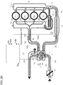
- FIG. 1 is a schematic constitutional view of a control device of a diesel engine 1 according to a first embodiment of the present invention.
- the diesel engine will be abbreviated to "engine” as necessary.
- FIGS. 2A and 2B are schematic constitutional views illustrating the essential parts of the engine 1 and a close-up of a turbo charger 3.
- FIG. 2A illustrates a state before opening an EGR valve 12 in a gas flow stagnation region
- FIG. 2B illustrates a state after opening the EGR valve 12 in the gas flow stagnation region.
- an intake compressor 3b of the turbo charger 3 is provided in an intake passage 2 of the diesel engine 1. Intake air is supercharged by the intake compressor 3b, and then cooled by an intercooler 4. The cooled intake air passes through a throttle valve 5, and then flows into a cylinder 41 of each cylinder upon passing through an intake air collector 6.
- the turbo charger 3 according to the present embodiment is provided with a variable nozzle 3c as shown in FIGS. 2A and 2B , but this variable nozzle 3c is not necessarily required.
- Fuel is supplied to the engine 1 by a common rail-type fuel injection device.
- the fuel is pressurized to a high degree by a high-pressure fuel pump 7 and fed to a common rail 8, and then the fuel is directly injected into the cylinders 41 from fuel injection valves 9 of the cylinders.
- the air which has flowed into the cylinders 41 and the fuel which has been injected become a mixed gas, and this mixed gas combusts by compression ignition within the cylinders 41.
- Exhaust gas flows out from the cylinders 41 to an exhaust passage 10.
- the intake passage 2 is constituted by an intake pipe 2a which is upstream of the intake compressor 3b, an intake pipe 2b which establishes communication between the intake compressor 3b and an inlet of the intercooler 4, an intake pipe 2c which establishes communication between an outlet of the intercooler 4 and the intake air collector 6, and the like.
- the EGR passage 11 is downstream of the throttle valve 5 and branches from the intake pipe 2c near the intake air collector 6. The remaining exhaust gas passes through an exhaust turbine 3a of the turbo charger 3 to drive the exhaust turbine 3a.
- "Fexh" indicates the flow of gas.
- An EGR cooler 31 is provided in the EGR passage 11.
- the EGR cooler 31 cools the EGR gas using cooling water or cooling air.
- a flow path switching valve 33 that switches the flow path of the EGR gas is provided at a branching part of a bypass passage 32 which bypasses the EGR cooler 31. For example, when no power is supplied, the flow path switching valve 33 blocks the bypass passage 32 to cause the EGR gas to flow to the EGR cooler 31, and when power is supplied, the flow path switching valve 33 blocks the passage on the EGR cooler 31 side to cause the EGR gas to flow to the bypass passage 32.
- the bypass passage 32 and the flow path switching valve 33 are provided as an HC measure during low temperatures.
- a four-cylinder engine is explained herein as an example of the engine 1 of the present embodiment.
- the cylinders are numbered from the top as #1, #2, #3, and #4.
- the EGR passage 11 is provided adjacent to the cylinder 41 of the #4 cylinder on the outside of the #4 cylinder.
- signals for an accelerator opening (amount of depression of the accelerator pedal) ACC from an accelerator sensor 22 and an engine rotation speed Ne from a crank angle sensor 23 are input into an engine controller 21.
- the engine controller 21 calculates a fuel injection timing and fuel injection amount Qdrv of a main injection based on the engine load (accelerator opening) and the engine rotation speed Ne, and outputs a valve-opening command signal corresponding to the fuel injection timing and fuel injection amount Qdrv to a fuel injection valve 9. Further, the engine controller 21 executes EGR control and supercharging pressure control in a coordinated manner so as to obtain a target EGR rate and a target intake air amount.
- the engine controller 21 is constituted by a microcomputer provided with a central processing unit (CPU), a read only memory (ROM), a random access memory (RAM), and an input/output interface (I/O interface).
- a filter (Diesel Particulate Filter) 13 that collects particulates in the exhaust gas is disposed downstream of the exhaust turbine in the exhaust passage 10. If a particulate deposit amount of the filter 13 reaches a predetermined value, the engine controller 21 executes regeneration processing of the filter 13. For example, regeneration processing of the filter 13 is carried out by raising the temperature of the exhaust gas to a temperature at which the particulates combust by performing a post injection during the expansion stroke or exhaust stroke immediately after the main injection. In this way, the particulates which have deposited on the filter 13 combust and are removed, and thereby the filter 13 is regenerated.
- the post injection amount and post injection timing are predetermined according to the engine operation conditions (load and rotation speed) so as to obtain a target regeneration temperature.
- an oxidation catalyst 14 made of a noble metal is disposed upstream of the filter 13.
- the exhaust gas components (HC, CO) which flow in due to the post injection are combusted by the oxidation catalyst 14 to raise the exhaust gas temperature, and thereby combustion of the particulates is promoted.
- An oxidation catalyst can also be coated onto a carrier which constitutes the filter 13. In this case, the oxidation reaction that occurs when the particulates combust is promoted, and thereby a bed temperature of the filter 13 can be raised and the combustion of the particulates can be further promoted.
- the catalyst is not limited to the oxidation catalyst 14.
- the oxidation catalyst can be replaced with another catalyst as long as the catalyst has an oxidation function.
- FIG. 1 illustrates a case in which a three-way catalyst (TWC) is used as the oxidation catalyst 14.
- TWC three-way catalyst
- An NOx trap catalyst (LNT) 15 is provided between the oxidation catalyst 14 and the filter 13.
- the NOx trap catalyst 15 adsorbs NOx (nitrogen oxide) within the exhaust gas in an oxygen atmosphere, and releases the trapped NOx in a reduction atmosphere to perform reduction/purification using HC in the exhaust gas as a reducing agent.
- An oxygen atmosphere is obtained when the excess air ratio of exhaust gas that has exited the cylinders 41 is greater than 1.0 (a value corresponding to the theoretical air/fuel ratio).
- a reduction atmosphere is obtained when the excess air ratio of exhaust gas that has exited the cylinders 41 is equal to or less than 1.0.
- the NOx deposit amount of the NOx trap catalyst 15 has reached a predetermined value, it is necessary to execute a rich spike process to switch the exhaust gas flowing through the NOx trap catalyst 15 from an oxygen atmosphere to a reduction atmosphere.
- the rich spike process post injection is carried out during the expansion stroke or exhaust stroke immediately after the main injection to increase the amount of unburned HC discharged to the exhaust passage 10 and supply the HC as a reducing agent to the NOx trap catalyst 15.
- the diesel engine 1 operates at an excess air ratio (lean-side air/fuel ratio) of a value higher than 1.0 (a value corresponding to the theoretical air/fuel ratio).
- the excess air ratio of the exhaust gas cannot be switched to 1.0 only by executing a post injection. Therefore, the amount of intake air flowing into the cylinders 41 (cylinder intake air amount) Qac is decreased by closing the throttle valve 5, which is in a fully opened position in normal operation, during the rich spike process, thereby switching the excess air ratio of exhaust gas that has exited the cylinders 41 to equal to or less than 1.0.
- the post injection amount and the throttle valve opening degree are determined so that the excess air ratio, which is determined by a fuel injection amount Qfuel, which is the total of the main fuel injection amount and the post injection amount, and the cylinder intake air amount Qac, becomes equal to or less than 1.0.
- the engine controller 21 calculates the NOx amount per predetermined duration of time that is trapped by the NOx trap catalyst 15 in each predetermined duration of time, and adds the NOx amounts per predetermined duration of time to calculate an NOx deposit amount which is deposited on the NOx trap catalyst 15. This NOx deposit amount is compared to a predetermined threshold, and when the NOx deposit amount has reached or exceeded the threshold, a post injection (rich spike process) for regenerating the NOx trap catalyst 15 is executed.
- the throttle valve opening degree is constricted from a fully opened state to a predetermined throttle valve opening degree, and the post injection is started accordingly.
- the post injection is completed after a certain amount of time has elapsed, and the throttle valve 5 is returned to the fully opened position.
- a target engine torque and a target excess air ratio according to the engine operation conditions are established.
- the engine controller 21 establishes the target drive torque from the accelerator opening and the engine rotation speed, and calculates the target engine torque based on the target drive torque.
- the operation conditions when starting the vehicle or when the vehicle is climbing a hill are in a region of low rotation speed and high load (non-EGR region).
- the operation region is divided into an EGR region and a non-EGR region.
- the portion designated as "Cnd1" indicates the operation conditions when starting the vehicle or when the vehicle is climbing a hill.
- the Cnd1 region will be expressed in the case of starting the vehicle.
- the engine torque increases when the turbo charger 3 operates well, but there is also a limit to this increase in the engine torque.
- the excess air ratio ⁇ of gas which is a mixture of air and fuel
- the engine 1 enters a state in which the engine torque does not rise even if the amount of fuel is further increased.
- the cause of the above phenomenon is found in the turbo charger 3. If the excess air ratio ⁇ of gas within the cylinders 41 approaches 1.0, the oxygen of the gas within the cylinders 41 becomes insufficient and the fuel does not combust completely, and thus the temperature and pressure of the combustion gas no longer rise. If the temperature and pressure of the combustion gas do not rise, the exhaust gas energy flowing into the exhaust turbine 3a does not increase, and thus the gas flow stagnates and the rotation speed of the exhaust turbine 3a settles at a fixed value. If the turbine rotation speed settles at a fixed value, the supercharging pressure does not rise and the intake air pushed into the cylinders 41 does not increase, and thus the engine torque does not increase even if the fuel amount is increased.
- the engine 1 it is determined on the basis of the operation conditions of the engine 1 whether or not the engine 1 is in a state in which the engine torque will not rise due to the turbo charger 3 even if the fuel amount is increased, such as when starting the vehicle.
- conditions in which the operation conditions of the engine 1 are in a gas flow stagnation region are newly established.
- the EGR valve 12 is opened, and fresh air of the intake pipe 2c downstream of the throttle valve 5 is made to flow via the EGR passage 11 into the exhaust passage 10 upstream of the exhaust turbine 3a.
- fresh air means intake air that does not include EGR gas.
- the conditions of being in the gas flow stagnation region include the following conditions ⁇ 1 > to ⁇ 3>.
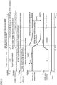
- FIG. 3 is a timing chart obtained upon verifying how the excess air ratio, engine torque, supercharging pressure, exhaust gas temperature, EGR valve opening degree, and main fuel injection amount Qdrv change when starting the vehicle.
- starting the vehicle is included in a region of low rotation speed and high load (non-EGR region), and thus the engine controller maintains the EGR valve in a fully closed state when starting the vehicle.
- the main fuel injection amount Qdrv which is supplied when starting the vehicle is constant.
- the actual supercharging pressure is higher than the exhaust gas pressure upstream of the exhaust turbine.
- the engine controller 21 opens the EGR valve 12 in the non-EGR region including when starting the vehicle so as to supply fresh air downstream of the intake compressor 3b to the exhaust passage 10.
- the flow path switching valve 33 blocks the passage on the EGR cooler 31 side in the non-EGR region including when starting the vehicle.
- fresh air of the intake pipe 2c downstream of the throttle valve 5 passes through the EGR passage 11 and the bypass passage 32 and flows into an exhaust manifold 10a (refer to FIG. 2B ).
- the present invention can also be applied to an engine which does not include the EGR cooler 31, the bypass passage 32, and the flow path switching valve 33. The following explanation assumes that the flow path switching valve 33 is constantly in a fully closed state.
- an exhaust port outlet temperature of the #4 cylinder and the inlet temperature of the exhaust turbine 3a are detected by temperature sensors.
- the exhaust passage 10 is constituted by the exhaust manifold 10a, an exhaust pipe 10b that establishes communication between a collection part of the exhaust manifold 10a and the inlet of the exhaust turbine 3a, an exhaust pipe 10c that establishes communication between the outlet of the exhaust turbine 3a and the inlet of the oxidation catalyst 14, and the like.
- the temperature sensor that detects the exhaust port outlet temperature of the #4 cylinder is attached at the position marked A shown in FIGS. 2A and 2B .
- the temperature sensor that detects the inlet temperature of the exhaust turbine 3a is attached at the position marked B of the exhaust pipe 10b shown in FIGS. 2A and 2B .
- the reason that the exhaust port outlet temperature of the #4 cylinder is detected rather than the exhaust port outlet temperatures of the # 1 to #3 cylinders is as follows.
- the exhaust port outlet of the #4 cylinder is closest to the point at which fresh air of the intake pipe 2c downstream of the intercooler 4 flows into the collection part of the exhaust manifold 10a, and thus it can be confirmed based on the temperature at this point whether fresh air of the intake pipe 2c downstream of the intercooler 4 has flowed into the exhaust manifold 10a.
- the inlet temperature of the exhaust turbine 3a is utilized because it can be confirmed based on this temperature whether after-burning of unburned fuel in the exhaust gas which has exited into in the exhaust manifold 10a is occurring.
- the exhaust port outlet temperature of the #4 cylinder and the inlet temperature of the exhaust turbine 3a when starting the vehicle are 670°C and 700°C respectively, and thus the temperature difference is 30°C.
- this level of temperature difference indicates that after-burning of the unburned fuel in the exhaust gas that has exited into the exhaust manifold 10a is occurring to a small degree.
- the opening degree of the EGR valve 12 is opened to a predetermined value TVO1, and fresh air downstream of the intercooler 4 flows into the exhaust manifold 10a as shown in FIG. 2B . Due to the fresh air that has flowed into the exhaust manifold 10a, in the present embodiment, the actual excess air ratio of the gas within the cylinders 41 and the actual excess air ratio of combustion gas within the exhaust manifold 10a differ from each other. In other words, in the present embodiment, the actual excess air ratio of the exhaust gas within the exhaust manifold 10a increases compared to that at t1 as shown by the first long dash-short dash line from the top in FIG.
- the actual supercharging pressure rises from t1, and matches the target supercharging pressure at the timing t3.
- the actual engine torque increases from t1 in accordance with the rise of the actual supercharging pressure, and matches the target engine torque at the timing t3.
- the exhaust port outlet temperature of the #4 cylinder decreases from 670°C to 580°C, and the inlet temperature of the exhaust turbine 3a decreases from 700°C to 670°C. In this way, the temperature difference between the two expands from 30°C before opening the EGR valve 12 to 90°C.
- the reason that the exhaust port outlet temperature of the #4 cylinder decreases from 670°C to 580°C is because fresh air of the intake pipe 2c downstream of the intercooler 4 has flowed via the EGR passage 11 into the exhaust manifold 10a at a position closest to the exhaust port outlet of the #4 cylinder.
- the engine controller 21 (EGR valve control function) originally placed the EGR valve 12 in a fully closed state.
- the engine controller 21 opens the EGR valve 12 in the non-EGR region. Therefore, in order to avoid interference with the EGR valve control function, in the present embodiment, the engine controller 21 performs control so as to open the EGR valve 12 preferentially over the EGR valve control function.
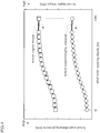
- FIG. 4 it is verified how the actual supercharging pressure and the actual engine torque change when the EGR opening degree is changed from 0% to 100% under the same conditions when starting the vehicle as shown in FIG. 3 .
- the actual supercharging pressure rises as the EGR opening degree is increased, and that the actual engine torque rises in accordance with the rise of the actual supercharging pressure.
- FIG. 5 is a flowchart for explaining the opening/closing control of the EGR valve 12. This control is executed at fixed time intervals (for example, every 10 ms).
- the engine controller 21 reads the main fuel injection amount Qdrv (amount corresponding to engine load), the engine rotation speed Ne, a supercharging pressure Pin, an exhaust gas pressure Pexh upstream of the exhaust turbine 3a, an O 2 concentration of the exhaust pipe 10b upstream of the exhaust turbine 3a, and an exhaust gas temperature Texh upstream of the exhaust turbine 3a.
- the main fuel injection amount Qdrv is calculated based on the accelerator opening and the engine rotation speed Ne. For example, as shown in FIG. 6 , a map of the main fuel injection amount is prepared in advance using the accelerator opening and the engine rotation speed Ne as parameters, and this map is searched to calculate the main fuel injection amount Qdrv.
- the engine rotation speed Ne is calculated based on a signal from the crank angle sensor 23.
- the supercharging pressure Pin which is the intake air pressure downstream of the intercooler 4, is detected by an intake air pressure sensor 51 provided to the intake air collector 6 downstream of the intercooler 4.
- the position at which the intake air pressure sensor 51 is provided is not limited to the intake air collector 6, and can be anywhere as long as it is downstream of the intake compressor 3b.
- the exhaust gas pressure Pexh upstream of the exhaust turbine 3a is detected by an exhaust gas pressure sensor 52 provided to the exhaust manifold 10a.
- the position at which the exhaust gas pressure sensor 52 is provided is not limited to the exhaust manifold 10a, and can be anywhere as long as it is upstream of the exhaust turbine 3a.
- the O 2 concentration of the exhaust passage 10 upstream of the exhaust turbine 3a is detected by an O 2 concentration sensor 53 provided to the exhaust pipe 10b upstream of the exhaust turbine 3a.
- the position at which the O 2 concentration sensor 53 is provided can be anywhere as long as it is between the outlet of the exhaust manifold 10a and the inlet of the oxidation catalyst 14.
- the exhaust gas temperature Texh upstream of the exhaust turbine 3a is detected by an exhaust gas temperature sensor 54 provided to the exhaust pipe 10b upstream of the exhaust turbine 3a.
- the position at which the exhaust gas temperature sensor 54 is provided is not limited to the exhaust pipe 10b, and can be anywhere as long as it is upstream of the exhaust turbine 3a.
- the supercharging pressure Pin, the exhaust gas pressure Pexh, the O 2 concentration in the exhaust gas, and the exhaust gas temperature Texh are detected by sensors, but these values can also be estimated using various parameters related to the engine operation conditions.
- Step 2 the engine controller 21 checks a torque increase permission flag.
- the torque increase permission flag is initially set to 0 during engine startup.
- Step 3 the engine controller 21 determines whether the engine operation conditions, which are determined from the Qdrv and the Ne, are in the non-EGR region.
- the EGR region is predetermined on a map using the engine rotation speed Ne and the main fuel injection amount Qdrv as parameters.
- the combustion speed of gas within the cylinders 41 is relatively slow due to the introduction of a portion of the exhaust gas into the intake air collector 6, and thereby NOx, which is produced when the combustion speed is relatively high, is suppressed.
- the exhaust gas pressure upstream of the exhaust turbine 3a must be higher than the supercharging pressure.
- the engine controller 21 opens the EGR valve 12, and thereby a portion of the fresh air of the intake pipe 2c downstream of the intercooler 4 is made to flow into the exhaust manifold 10a.
- the engine controller 21 controls the EGR valve 12 to be fully opened in Step 9.
- Step 4 to 6 are processes for determining whether the engine operation conditions are in the gas flow stagnation region.
- the engine controller 21 observes whether the following conditions ⁇ 1 > to ⁇ 3> are satisfied, and when all of the conditions are satisfied, it is determined that the engine operation conditions are in the gas flow stagnation region. If the operation conditions are in the gas flow stagnation region, the engine controller 21 sets the torque increase permission flag to 1 in Step 7 and controls the EGR valve 12 to be fully opened in Step 8 in order to permit the engine torque to increase.
- ⁇ 1 > is a condition is as follows. If the O 2 concentration in the exhaust gas upstream of the oxidation catalyst 14 in the non-EGR region becomes an O 2 concentration of less than 5%, even if the fuel amount is further increased, the combustion of fuel in the gas within the cylinders 41 becomes poor due to insufficient oxygen in the gas within the cylinders 41, and the gas flow entering the exhaust turbine 3a stagnates and the turbine rotation speed becomes fixed. If the turbine rotation speed becomes fixed, the intake compressor 3b which is coaxial with the exhaust turbine 3a cannot compress the intake air any further, and thus the actual supercharging pressure also settles at a fixed value. If the actual supercharging pressure settles at a fixed value, the actual engine torque cannot increase any further.
- 5% is an upper limit value within the O 2 concentration range at which the actual engine torque will not increase any further even if the amount of fuel is further increased.
- the oxygen in the gas within the cylinders 41 does not become insufficient. If the fuel amount is increased in a state in which the oxygen in the gas within the cylinders 41 does not become insufficient, the fuel in the gas within the cylinders 41 combusts satisfactorily and the engine torque increases. Thus, it is not necessary to purposely open the EGR valve 12 to allow fresh air to flow in.
- the actual excess air ratio of gas within the cylinders 41 in the non-EGR region is compared to the threshold of 1.05.
- the actual excess air ratio of gas within the cylinders 41 in the non-EGR region is less than 1.05, it can be determined that the engine torque will not increase any further even if the fuel amount is increased.
- the fuel used in the diesel engine 1 is an aggregate of hydrocarbons which can take various values for the numbers of C (carbon) and H (hydrogen). Therefore, even if the actual excess air ratio ⁇ real calculated by the equation in (1) above is the same at 1.0, the O 2 concentration in the gas within the cylinders 41 may differ depending on the fuel used. When the calculated actual excess air ratio is 1.0, the actual O 2 concentration was about 2% upon detecting the O 2 concentration in the fuel used in experimentation. In this way, in commercially available fuels, the actual excess air ratio as calculated by the equation in (1) above and the actual O 2 concentration detected by an O 2 concentration sensor do not necessarily correspond accurately, and may vary within a certain allowable range.
- the O 2 concentration of 5% discussed above is merely given as a representative value, and the O 2 concentration is actually set to an appropriate value between 0% and 5%.
- the excess air ratio of 1.05 discussed above as a threshold is also merely given as a representative value, and an appropriate value between 1.0 and 1.1 is actually selected as the threshold.
- ⁇ 2> is a condition is as follows. If the supercharging pressure Pin is equal to or less than the exhaust gas pressure Pexh upstream of the exhaust turbine 3a, fresh air of the intake pipe 2c downstream of the intercooler 4 cannot flow into the exhaust manifold 10a via the EGR passage 11 and the bypass passage 32. The condition in ⁇ 2> establishes a condition in which fresh air of the intake pipe 2c downstream of the intercooler 4 can flow into the exhaust manifold 10a.
- ⁇ 3> is a condition. In order to after-burn the unburned fuel in the exhaust gas that has exited from the cylinders 41 to the exhaust manifold 10a using fresh air introduced into the exhaust manifold 10a, it is favorable for the ambient temperature of the gas to be after-burned to be relatively high. After-burning can occur satisfactorily in a temperature range of 700°C or higher.
- the condition in ⁇ 3> is a temperature condition at which after-burning of the unburned fuel in the exhaust gas that has exited from the cylinders 41 to the exhaust manifold 10a will reliably occur. After-burning can still occur even if the ambient temperature of the gas to be after-burned is relatively low at less than 700°, and thus Step 6 can be eliminated.
- the engine controller 21 determines that the engine operation conditions are in the gas flow stagnation region, and thus executes the process of Step 8.
- Step 8 is a process in which the engine controller 21 executes control of the EGR valve 12 preferentially.
- the EGR valve 12 should be controlled to be fully closed according to the EGR valve control function, but instead the EGR valve 12 is controlled to be fully opened in Step 8.
- “preferentially” means that the EGR valve 12 is controlled to be fully opened without performing control to fully close the EGR valve 12 according to the EGR valve control function.
- the rotation speed of the intake compressor 3b which is coaxial with the exhaust turbine 3a rises, and the actual supercharging pressure also rises accordingly. If the supercharging pressure rises, the amount of fresh air flowing into the cylinders 41 increases, and thus the combustion state of the fuel in the gas within the cylinders 41 improves and the actual engine torque increases.
- the EGR valve opening degree when opening the EGR valve 12 in Step 8 is adjusted to a pre-set appropriate opening degree.
- the target supercharging pressure is determined according to the engine operation conditions.
- the opening degree (opening ratio) of the variable nozzle 3c is feedback controlled so that the actual supercharging pressure Pin when starting the vehicle, which is detected by the intake air pressure sensor 51, matches the target supercharging pressure.
- the target supercharging pressure cannot be obtained (refer to the third in FIG. 3 ).
- the EGR valve opening degree when the EGR valve 12 is opened is set so that the actual supercharging pressure can reach the target supercharging pressure when recombustion of the unburned fuel in the exhaust gas has been carried out by opening the EGR valve 12 so that the gas flow stagnation is temporarily lifted and the actual supercharging pressure has increased.
- the amount of fresh air or the amount of fuel can be feedback controlled so that the actual excess air ratio of gas within the cylinders 41 matches the target excess air ratio.
- the target excess air ratio cannot be obtained (refer to the first in FIG. 3 ).
- the EGR valve 12 is opened, the actual excess air ratio of the exhaust gas within the exhaust manifold 10a changes to become greater than the actual excess air ratio of gas within the cylinders 41.
- the EGR valve opening degree is set so that the actual excess air ratio of the exhaust gas within the exhaust manifold 10a which has changed matches the target air excess ratio.
- the engine controller 21 determines that the engine operation conditions are not in the gas flow stagnation region, and the EGR valve 12 is controlled to be in a fully closed state in Step 10.
- Step 11 When the torque increase permission flag is 1, the engine controller 21 executes the process of Step 11 after executing Step 2.
- Steps 11 to 14 are processes for establishing the conditions for cancelling the permission for torque increase after the engine torque increase has been permitted.
- the engine controller 21 determines whether the following conditions ⁇ 11> to ⁇ 14> are satisfied. If one of the conditions is satisfied, then it is determined that the conditions for cancelling the permission for torque increase have been met.
- the engine controller 21 returns the torque increase permission flag to 0 in Step 15, and controls the EGR valve 12 to a fully closed state in Step 16.
- Step 6 may be eliminated, and when Step 6 is eliminated, Step 14 may also be eliminated.
- the EGR valve 12 when the conditions for cancelling the permission for torque increase have been met after the engine torque increase has been permitted, the EGR valve 12 is fully closed.
- the EGR valve 12 can be controlled to a fully closed state when a certain predetermined duration of time has elapsed from the timing at which the engine torque increase was permitted.
- the fixed duration of time is set as a time during which the driver desires an acceleration feeling when starting the vehicle.
- the EGR valve 12 can be controlled to a fully closed state when either the conditions for cancelling the permission for torque increase have been met or the fixed duration of time has passed from the timing at which the engine torque increase was permitted.
- the engine 1 of the present embodiment includes the turbo charger 3, the fresh air/secondary air supply device consisting of the EGR passage 11 and the EGR valve 12, and the engine controller 21.
- the turbo charger 3 coaxially joins the intake compressor 3b and the exhaust turbine 3a, and drives the intake compressor 3b with energy of exhaust gas which flows into the exhaust turbine 3a to pressurize intake air which flows into the intake compressor 3b.
- the fresh air/secondary air supply device 11,12 is constituted to be capable of supplying fresh air to the exhaust manifold 10a.
- the engine controller 21 determines whether the engine operation conditions are in a gas flow stagnation region, and when the engine operation conditions are in the gas flow stagnation region, the engine controller 21 causes the fresh air/ secondary air supply device 11,12 to operate and supply fresh air to the exhaust manifold 10a.
- the actual supercharging pressure rises compared to before supplying the fresh air. If the actual supercharging pressure rises, the actual engine torque can be increased by the amount of rise of the actual supercharging pressure. Thereby, a desired acceleration feeling can be obtained even in the gas flow stagnation region such as when starting the vehicle.
- the fresh air/secondary air supply device 11,12 constitutes a portion of the EGR control device.
- the EGR control device includes the EGR passage 11, the normally-closed EGR valve 12, and the engine controller 21.
- the EGR passage 11 recirculates a portion of the exhaust gas to the intake passage 2.
- the EGR valve 12 opens/closes the EGR passage 11.
- the engine controller 21 determines whether the engine operation conditions are in the EGR region or in the non-EGR region which includes the gas flow stagnation region.
- the engine controller 21 opens the EGR valve 12 when the engine operation conditions are in the EGR region, and closes the EGR valve 12 when the engine operation conditions are in the non-EGR region.
- the engine controller 21 opens the EGR valve 12 when the engine operation conditions are in the gas flow stagnation region, so as to supply fresh air downstream of the intercooler 4 to the exhaust manifold 10a.
- the engine controller 21 gives preference to control for fully opening the EGR valve 12 when the engine operation conditions are in the gas flow stagnation region over control for fully closing the EGR valve 12 according to the EGR valve control function.
- the engine 1 of the present embodiment includes the O 2 concentration sensor 53, and the engine controller 21 which compares the intake air pressure Pin downstream of the intake compressor 3b with the exhaust gas pressure Pexh upstream of the exhaust turbine 3a. If the O 2 concentration in the exhaust gas is at least zero and the intake air pressure Pin downstream of the intake compressor 3b is higher than the exhaust gas pressure Pexh upstream of the exhaust turbine 3a, the engine controller 21 determines that the engine operation conditions are in the gas flow stagnation region. Alternatively, if the excess air ratio of gas within the cylinders is at least 1.0 and the intake air pressure downstream of the intake compressor 3b is higher than the exhaust gas pressure upstream of the exhaust turbine 3a, the engine controller 21 determines that the engine operation conditions are in the gas flow stagnation region. Thereby, it can be determined with good accuracy whether the engine operation conditions are in the gas flow stagnation region on the basis of the engine operation conditions (O 2 concentration in the exhaust gas, excess air ratio of gas within the cylinders, intake air pressure Pin, exhaust gas pressure Pexh).
- the engine controller 21 determines that the engine operation conditions are in the gas flow stagnation region. Thereby, after-burning of unburned fuel in the exhaust gas that has exited from the cylinders 41 to the exhaust manifold 10a can be reliably achieved.
- the gas flow stagnation region includes when starting the vehicle. Thereby, a desired acceleration feeling can be obtained when starting the vehicle.
- the turbo charger 3 has the variable nozzle 3c. Further, the engine controller 21 sets a target supercharging pressure according to the engine operation conditions, and feedback controls the opening degree of the variable nozzle 3c so that the actual supercharging pressure matches the target supercharging pressure. When the EGR valve 12 is opened, the engine controller 21 sets the EGR valve opening degree when the EGR valve 12 is opened so that the actual supercharging pressure matches the target supercharging pressure. Thereby, a desired supercharging pressure (target supercharging pressure) can be obtained even in a low-rotation-speed high-load region such as when starting the vehicle.
- FIGS. 8A and 8B are schematic constitutional views illustrating the essential parts of the engine 1 and a close-up of the turbo charger 3 in a second embodiment for describing the invention's technical background.
- FIG. 8A illustrates a state before opening the EGR valve 12 when the state of the turbo charger 3 is in a gas flow stagnation region
- FIG. 8B illustrates a state after opening the EGR valve 12 when the state of the turbo charger 3 is in the gas flow stagnation region.
- Those portions which are identical to FIGS. 2A and 2B of the first embodiment will be assigned identical reference numerals.
- the engine controller 21 determined whether the engine operation conditions are in the gas flow stagnation region based on whether all of the conditions in ⁇ 1> to ⁇ 3> are satisfied. In the second embodiment, the engine controller 21 determines whether the state of the turbo charger 3 is in the gas flow stagnation region based on whether an operation point of the exhaust turbine 3a is in a gas flow stagnation region, which has been preset on a turbine performance curve (exhaust turbine performance curve characteristics). More specifically, in the first embodiment, it was determined whether the engine operation conditions are in the gas flow stagnation region, whereas in the second embodiment, it is determined whether the state of the turbo charger 3 is in the gas flow stagnation region.
- the operation point of the exhaust turbine 3a is an operation point of the exhaust turbine 3a determined from an expansion ratio and a gas flow rate in the turbine performance curve shown in FIG. 10 .
- the inlet pressure Ptin of the exhaust turbine 3a is detected by an exhaust gas pressure sensor 52 provided in the exhaust manifold 10a as shown in FIGS. 8A and 8B .
- the outlet pressure Ptout of the exhaust turbine 3a is detected by an outlet pressure sensor 61 provided in the exhaust pipe 10c as shown in FIGS. 8A and 8B .
- the gas flow rate Qexh of gas flowing through the exhaust turbine 3a is detected by a gas flow rate sensor 62 provided in the exhaust pipe 10b as shown in FIGS. 8A and 8B .
- the inlet pressure Ptin of the exhaust turbine 3a, the outlet pressure Ptout of the exhaust turbine 3a, and the gas flow rate Qexh detected by the above sensors 52, 61, and 62 are input into the engine controller 21.
- FIG. 9 is a flowchart for explaining the opening/closing control of the EGR valve 12. This control is executed at fixed time intervals (for example, every 10 ms). Processes which are identical to those in the flowchart of FIG. 5 for the first embodiment will be assigned the same reference numerals.
- Steps 21 to 25 The processes which differ from those of the flowchart of FIG. 5 for the first embodiment are Steps 21 to 25.
- Steps 4 to 6 of FIG. 5 of the first embodiment are replaced with Steps 22 and 23 of FIG. 9 of the present embodiment.
- Steps 12 to 14 of FIG. 5 of the first embodiment are replaced with Steps 24 and 25 of FIG. 9 of the present embodiment.
- the engine controller 21 reads the main fuel injection amount Qdrv, the engine rotation speed Ne, the inlet pressure Ptin of the exhaust turbine 3a, the outlet pressure Ptout of the exhaust turbine 3a, and the gas flow rate Qexh of gas flowing through the exhaust turbine 3a.
- the inlet pressure Ptin of the exhaust turbine 3a is detected by the exhaust gas pressure sensor 52
- the outlet pressure Ptout of the exhaust turbine 3a is detected by the outlet pressure sensor 61
- the gas flow rate Qexh [g/s] of gas flowing through the exhaust turbine 3a is detected by the gas flow rate sensor 62.
- the gas flow rate Qexh of gas flowing through the exhaust turbine 3a can be estimated using parameters indicating the engine operation state.
- Step 22 the engine controller 21 calculates the expansion ratio [dimensionless number] of the exhaust turbine 3a from the inlet pressure Ptin of the exhaust turbine 3a and the outlet pressure Ptout of the exhaust turbine 3a using the above-mentioned equation (2).
- Step 23 the engine controller 21 determines whether the operation point of the exhaust turbine 3a, which is determined from the expansion ratio of the exhaust turbine 3a and the gas flow rate of gas flowing through the exhaust turbine 3a, is in a gas flow stagnation region Rstb1 (refer to the hatched region) on the turbine performance curve shown in FIG. 10 .
- the expansion ratio [dimensionless number] of the exhaust turbine 3a is shown on the horizontal axis
- the gas flow rate [g/s] of gas flowing through the exhaust turbine 3a is shown on the vertical axis.
- the turbine performance curve shows how the operation point of the exhaust turbine 3a changes due to differences in the engine operation conditions.
- the position of the operation point of the exhaust turbine 3a moves, for example, as shown by the square marks in FIG. 10 due to changes in the engine operation conditions.
- the operation point of the exhaust turbine 3a when starting the vehicle is at the position of point C, where both the expansion ratio and the gas flow rate are small.
- the gas flow stagnation region Rstb1 is predetermined so as to include the operation point (point C) of the exhaust turbine 3a when starting the vehicle in current engines as well as the region on the side in which the expansion ratio and gas flow rate are smaller than those at the point C.
- the gas flow stagnation region Rstb1 is set so as to cover up to a region on the side in which the expansion ratio and gas flow rate are slightly larger than those at the point C. This is because fluctuations exist in the operation point of the exhaust turbine 3a when starting the vehicle, and thus the gas flow stagnation region Rstb1 is set in consideration of such fluctuations.
- Step 10 when the operation point of the exhaust turbine 3a determined from the expansion ratio and the gas flow rate is not in the gas flow stagnation region Rstb1 shown in FIG. 10 , in Step 10, the engine controller 21 controls the EGR valve 12 to a fully closed state.
- Step 23 if it is determined in Step 23 that the operation point of the exhaust turbine 3a determined from the expansion ratio and the gas flow rate is in the gas flow stagnation region Rstb1 shown in FIG. 10 , the engine controller 21 determines that the state of the turbo charger 3 is in the gas flow stagnation region. At this time, the engine controller 21 proceeds to Steps 7 and 8 for permitting an increase in the engine torque, in which the engine controller 21 sets the torque increase permission flag to 1 and opens the EGR valve 12.
- Step 2 If it is determined in Step 2 that the torque increase permission flag is 1, the engine controller 21 executes the process of Step 11. If it is determined in Step 11 that the engine control conditions are in the non-EGR region, the engine controller 21 executes the process of Step 24, and calculates the expansion ratio of the exhaust turbine 3a in the same manner as in Step 22. In Step 25, the engine controller 21 determines whether the operation point of the exhaust turbine 3a determined from the expansion ratio and the gas flow rate is in the gas flow stagnation region Rstb1 shown in FIG. 10 . If the operation point of the exhaust turbine 3a is in the gas flow stagnation region Rstb1, the engine controller 21 determines that the state of the turbo charger 3 continues to be in the gas flow stagnation region, and thus executes the processes of Steps 7 and 8.
- Step 25 if it is determined in Step 25 that the turbine operation point is outside of the gas flow stagnation region Rstb1, the engine controller 21 sets the torque increase permission flag to 0 in Step 15, and controls the EGR valve 12 to a fully closed state in Step 16.
- the EGR valve 12 when the state of the turbo charger 3 deviates from the gas flow stagnation region Rstb1 after the increase in the engine torque has been permitted, the EGR valve 12 is fully closed.
- the present embodiment is not limited thereto.
- the EGR valve 12 can be controlled to a fully closed state when a certain predetermined duration of time has elapsed from the timing at which the engine torque increase was permitted.
- the fixed duration of time is set as a time during which the driver desires an acceleration feeling when starting the vehicle.
- the EGR valve 12 can be controlled to a fully closed state when either the state of the turbo charger 3 has deviated from the gas flow stagnation region Rstb1 or the fixed duration of time has passed from the timing at which the engine torque increase was permitted.
- the engine 1 includes the gas flow rate sensor 62 and the engine controller 21.
- the engine controller 21 calculates the expansion ratio, and stores a turbine performance curve (exhaust turbine performance curve characteristics) using the calculated expansion ratio and the gas flow rate as parameters.
- the engine controller 21 determines whether the state of the turbo charger 3 is in the gas flow stagnation region based on whether an operation point of the exhaust turbine 3a, which is determined from the calculated expansion ratio and the detected gas flow rate, is in a gas flow stagnation region, which has been preset on the turbine performance curve. Thereby, it can be determined whether the state of the turbo charger 3 is in the gas flow stagnation region without using an expensive sensor such as the O 2 concentration sensor 53, and without being based on the engine operation conditions.
- the engine 1 has an exhaust turbine 3a monitoring device consisting of the sensors 52, 61, and 62 and the engine controller 21.
- the exhaust turbine 3a monitoring device finds the expansion ratio and the gas flow rate and monitors where the operation point of the exhaust turbine 3a, which is determined from the expansion ratio and the gas flow rate, is located on the turbine performance curve shown in FIG. 10 . Therefore, if the exhaust turbine 3a monitoring device already exists in the engine 1, then it can be determined whether the state of the turbo charger 3 is in the gas flow stagnation region by merely adding software (the flow of FIG. 9 ), and thus cost increases can be avoided.
- FIGS. 11A and 11B are schematic constitutional views illustrating the essential parts of the engine 1 and a close-up of the turbo charger 3 in a third embodiment for describing the invention's technical background.
- FIG. 11A illustrates a state before opening the EGR valve 12 when the state of the turbo charger 3 is in a gas flow stagnation region
- FIG. 11B illustrates a state after opening the EGR valve 12 when the state of the turbo charger 3 is in the gas flow stagnation region.
- Those portions which are identical to FIGS. 2A and 2B of the first embodiment will be assigned identical reference numerals.
- the engine controller 21 determined whether the engine operation conditions are in the gas flow stagnation region based on whether all of the conditions in ⁇ 1> to ⁇ 3> are satisfied.
- the engine controller 21 determines whether the state of the turbo charger 3 is in the gas flow stagnation region based on whether an operation point of the intake compressor 3b is in a gas flow stagnation region, which has been preset on a compressor performance curve (intake compressor performance curve characteristics). More specifically, in the first embodiment, it was determined whether the engine operation conditions are in the gas flow stagnation region, whereas in the third embodiment, it is determined whether the state of the turbo charger 3 is in the gas flow stagnation region similar to the second embodiment.
- the state of the turbo charger 3 is in the gas flow stagnation region is a concept including a case in which the operation point of the intake compressor is in the gas flow stagnation region on the compressor performance curve and a case in which the operation point of the exhaust turbine is in the gas flow stagnation region on the turbine performance curve.
- the operation point of the intake compressor 3b is an operation point of the intake compressor 3b determined from a pressure ratio and a compressor flow rate in the compressor performance curve shown in FIG. 13 .
- the pressure ratio of the intake compressor 3b is the ratio of an outlet pressure Pcout of the intake compressor 3b and the inlet pressure Pcin of the intake compressor 3b, and is calculated by the following equation.
- Pressure Ratio Pcout / Pcin
- the outlet pressure Pcout of the intake compressor 3b is detected by an outlet pressure sensor 72 provided in the intake pipe 2b downstream of the intake compressor 3b and upstream of the intercooler 4 as shown in FIGS. 11A and 11B .
- the inlet pressure Pcin of the intake compressor 3b is detected by an inlet pressure sensor 71 provided in the intake pipe 2a downstream of the air flowmeter 55 and upstream of the intake compressor as shown in FIGS. 11A and 11B .
- the compressor flow rate Qcmp is detected by the air flowmeter 55 as shown in FIGS. 11A and 11B .
- the outlet pressure Pcout of the intake compressor 3b, the inlet pressure Pcin of the intake compressor 3b, and the compressor flow rate Qcmp detected by the sensors 72, 71, and 55 are input into the engine controller 21.
- FIG. 12 is a flowchart for explaining the opening/closing control of the EGR valve 12 in the third embodiment. This control is executed at fixed time intervals (for example, every 10 ms). Processes which are identical to those in the flowchart of FIG. 5 for the first embodiment will be assigned the same reference numerals.
- Steps 31 to 35 The processes which differ from those of the flowchart of FIG. 5 for the first embodiment are Steps 31 to 35.
- Steps 4 to 6 of FIG. 5 of the first embodiment are replaced with Steps 32 and 33 of FIG. 12 of the third embodiment.
- Steps 12 to 14 of FIG. 5 of the first embodiment are replaced with Steps 34 and 35 of FIG. 12 of the third embodiment.
- the engine controller 21 reads the main fuel injection amount Qdrv, the engine rotation speed Ne, the outlet pressure Pcout of the intake compressor 3b, the inlet pressure Pcin of the intake compressor 3b, and the compressor flow rate Qcmp.
- the outlet pressure Pcout of the intake compressor 3b is detected by the outlet pressure sensor 72
- the inlet pressure Pcin of the intake compressor 3b is detected by the inlet pressure sensor 71
- the compressor flow rate Qcmp [g/s] is detected by the air flowmeter 55.
- Step 3 If it is determined in Step 3 that the engine operation conditions are in the non-EGR region, the engine controller 21 executes the process of Step 32 to calculate the pressure ratio [dimensionless number] of the intake compressor 3b from the outlet pressure Pcout of the intake compressor 3b and the inlet pressure Pcin of the intake compressor 3b using the above-mentioned equation (3).
- Step 33 the engine controller 21 determines whether the operation point of the intake compressor 3b, which is determined from the pressure ratio of the intake compressor 3b and the compressor flow rate, is in a gas flow stagnation region Rstb2 (refer to the hatched region) on the compressor performance curve shown in FIG. 13 .
- the compressor flow rate [g/s] is shown on the horizontal axis
- the pressure ratio [dimensionless number] of the intake compressor 3b is shown on the vertical axis.
- the compressor performance curve shows how the operation point of the intake compressor 3b changes due to differences in the engine operation conditions.
- "Leffi” represents an equivalent compressor efficiency line
- “Lrot” represents a line in which the exhaust turbine 3a rotation speed is fixed.
- the position of the operation point of the intake compressor 3b moves, for example, as shown by the square marks in FIG. 13 due to changes in the engine operation conditions.
- the gas flow stagnation region Rstb2 is predetermined so as to include the operation point (point E) of the intake compressor 3b when starting the vehicle in current engines as well as the region on the side in which the pressure ratio and compressor flow rate are smaller than those at the point E.
- the gas flow stagnation region Rstb2 is set so as to cover up to a region on the side in which the pressure ratio and compressor flow rate are slightly larger than those at the point E. This is because fluctuations exist in the operation point of the intake compressor 3b when starting the vehicle, and thus the gas flow stagnation region Rstb2 is set in consideration of such fluctuations.
- Step 10 when it is determined in Step 33 that the operation point of the intake compressor 3b is not in the gas flow stagnation region Rstb2 shown in FIG. 13 , in Step 10, the engine controller 21 controls the EGR valve 12 to a fully closed state.
- the engine controller 21 determines that the state of the turbo charger 3 is in the gas flow stagnation region. In this case, the engine controller 21 sets the torque increase permission flag to 1 in Step 7 and opens the EGR valve 12 in Step 8 in order to permit an increase in the engine torque.
- Step 2 If it is determined in Step 2 that the torque increase permission flag is 1, the engine controller 21 executes the process of Step 11. If it is determined in Step 11 that the engine control conditions are in the non-EGR region, in Step 34, the engine controller 21 calculates the pressure ratio of the intake compressor 3b in the same manner as in Step 32. In Step 35, the engine controller 21 determines whether the compressor operation point determined from the pressure ratio and the compressor flow rate is in the gas flow stagnation region Rstb2 shown in FIG. 13 . If the operation point of the intake compressor 3b is in the gas flow stagnation region Rstb2 shown in FIG. 13 , the engine controller 21 determines that the state of the turbo charger 3 continues to be in the gas flow stagnation region. In this case, the engine controller 21 executes the processes of Steps 7 and 8.
- the outlet pressure (pressure ratio) of the intake compressor 3b increases and the compressor flow rate increases compared to before the EGR valve 12 was opened.
- the operation point of the intake compressor 3b when starting the vehicle moves to a point F in FIG. 13 at which the pressure ratio is higher than at the point E and the compressor flow rate is higher than at the point E.
- the rotation speed of the intake compressor 3b increases accordingly.
- the actual supercharging pressure rises to the target supercharging pressure, and the actual engine torque increases.
- the compressor efficiency is also higher than at the point E, and thereby the turbo charger 3 can be operated efficiently.
- Step 35 if it is determined in Step 35 that the compressor operation point is outside of the gas flow stagnation region Rstb2, the engine controller 21 sets the torque increase permission flag to 0 in Step 15, and controls the EGR valve 12 to a fully closed state in Step 16.
- the EGR valve 12 when the state of the turbo charger 3 deviates from the gas flow stagnation region Rstb2 after the increase in the engine torque has been permitted, the EGR valve 12 is fully closed.
- the present embodiment is not limited thereto.
- the EGR valve 12 can be controlled to a fully closed state when a certain predetermined duration of time has elapsed from the timing at which the engine torque increase was permitted.
- the fixed duration of time is set as a time during which the driver desires an acceleration feeling when starting the vehicle.
- the EGR valve 12 can be controlled to a fully closed state when either the state of the turbo charger 3 has deviated from the gas flow stagnation region Rstb2 or the fixed duration of time has passed from the timing at which the engine torque increase was permitted.
- the engine 1 includes the air flowmeter 55 and the engine controller 21.
- the engine controller 21 calculates the pressure ratio, and stores a compressor performance curve (intake compressor performance curve characteristics) using the calculated pressure ratio and the compressor flow rate as parameters.
- the engine controller 21 determines whether the state of the turbo charger 3 is in the gas flow stagnation region based on whether a compressor operation point, which is determined from the pressure ratio and the compressor flow rate Qcmp, is in the gas flow stagnation region, which has been preset on the intake compressor performance curve characteristics. Thereby, it can be determined whether the state of the turbo charger 3 is in the gas flow stagnation region without using an expensive sensor such as the O 2 concentration sensor 53, and without being based on the engine operation conditions.
- the engine 1 has an intake compressor 3b monitoring device consisting of the sensors 55, 71, and 72 and the engine controller 21.
- the intake compressor 3b monitoring device finds the pressure ratio and the compressor flow rate and monitors where the operation point of the intake compressor 3b, which is determined from the pressure ratio and the compressor flow rate, is located on the compressor performance curve shown in FIG. 13 . Therefore, if the intake compressor 3b monitoring device already exists in the engine 1, then it can be determined whether the state of the turbo charger 3 is in the gas flow stagnation region by merely adding software (the flow of FIG. 12 ), and thus cost increases can be avoided.
- the third embodiment can be combined with the second embodiment.
- the engine controller 21 determines whether the state of the turbo charger 3 is in the gas flow stagnation region based on the operation point of the exhaust turbine 3a, and determines whether the state of the turbo charger 3 is in the gas flow stagnation region based on the operation point of the intake compressor 3b.
- the engine controller 21 opens the EGR valve 12 if it is determined by either of the above that the state of the turbo charger 3 is in the gas flow stagnation region, or if it is determined by both of the above that the state of the turbo charger 3 is in the gas flow stagnation region.
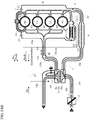
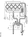
- FIGS. 14A and 14B are schematic constitutional views illustrating the essential parts of the engine 1 and a close-up of the turbo charger 3 in a fourth embodiment.
- FIG. 14A illustrates a state before opening a bypass valve 82 when the engine operation conditions are in the gas flow stagnation region
- FIG. 14B illustrates a state after opening the bypass valve 82 when the engine operation conditions are in the gas flow stagnation region.
- Those portions which are identical to FIGS. 2A and 2B of the first embodiment will be assigned identical reference numerals.
- the engine 1 in the first embodiment, fresh air of the intake pipe 2c downstream of the intake compressor 3b was made to flow into the exhaust manifold 10a by opening the EGR valve 12 in the gas flow stagnation region.
- the engine 1 according to the fourth embodiment also includes, separate from the EGR passage 11, a bypass passage 81 that bypasses the cylinders 41 to establish communication between the intake air collector 6 and the exhaust manifold 10a, and a normally-closed bypass valve 82 that opens/closes the bypass passage 81.
- the bypass passage 81 is provided outside of the #1 cylinder 41 along the #1 cylinder 41, but the position at which the bypass passage 81 is provided is not limited thereto.
- the engine controller 21 opens the bypass valve 82 when the engine operation conditions are in the gas flow stagnation region such as when starting the vehicle, and thereby fresh air downstream of the intake compressor 3b is made to flow into the exhaust manifold 10a.
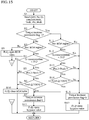
- FIG. 15 is a flowchart for explaining the opening/closing control of the EGR valve 12 and the bypass valve 82 in the fourth embodiment. This control is executed at fixed time intervals (for example, every 10 ms). Processes which are identical to those in the flowchart of FIG. 5 for the first embodiment will be assigned the same reference numerals.
- the engine controller 21 executes the processes of Steps 7 and 41 in order to permit an increase in the engine torque.
- the engine controller 21 sets the torque increase permission flag to 1 in Step 7, and controls the bypass valve 82 to a fully opened state in Step 41.
- the engine controller 21 performed control to open the EGR valve 12, but in the fourth embodiment, the engine controller 21 opens the bypass valve 82 instead of the EGR valve 12, and thus it is not necessary to execute control to open the EGR valve 12.
- Step 11 to 14 are processes for establishing the conditions for cancelling the permission for torque increase after the engine torque increase has been permitted.
- the engine controller 21 determines whether the above-described conditions ⁇ 11> to ⁇ 14> are satisfied. If one of the conditions is satisfied, then it is determined that the conditions for cancelling the permission for torque increase have been met. When the cancellation conditions have been met, the engine controller 21 returns the torque increase permission flag to 0 in Step 15, and controls the bypass valve 82 to a fully closed state in Step 42.
- the bypass valve 82 is controlled to a fully closed state when the conditions for cancelling the permission for torque increase have been met after the engine torque increase has been permitted.
- the present embodiment is not limited thereto.
- the bypass valve 82 can be controlled to a fully closed state when a certain predetermined duration of time has elapsed from the timing at which the engine torque increase was permitted.
- the fixed duration of time is set as a time during which the driver desires an acceleration feeling when starting the vehicle.
- the bypass valve 82 can be controlled to a fully closed state when either the conditions for cancelling the permission for torque increase have been met or the fixed duration of time has passed from the timing at which the engine torque increase was permitted.
- the fresh air/secondary air supply device is constituted by the bypass passage 81 and the normally-closed bypass valve 82 that opens/closes the bypass passage 81.
- the bypass passage 81 bypasses the cylinders 41 to establish communication between the intake passage downstream of the intake compressor 3b and the exhaust manifold 10a. If the engine operation conditions are in the gas flow stagnation region, the engine controller 21 executes bypass valve control to open the bypass valve 82 and supply fresh air downstream of the intake compressor 3b to the exhaust manifold 10a.
- the fourth embodiment similar to the first embodiment, by supplying fresh air to the exhaust manifold 10a in the gas flow stagnation region, the actual supercharging pressure rises compared to before supplying the fresh air. If the actual supercharging pressure rises, the actual engine torque can be increased by the amount of rise of the actual supercharging pressure.
- FIGS. 16A and 16B are schematic constitutional views illustrating the essential parts of the engine 1 and a close-up of the turbo charger 3 in a fifth embodiment.
- FIG. 16A illustrates a state before opening a secondary air supply valve 102 when the engine operation conditions are in the gas flow stagnation region
- FIG. 16B illustrates a state after opening the secondary air supply valve 102 when the engine operation conditions are in the gas flow stagnation region.
- Those portions which are identical to FIGS. 2A and 2B of the first embodiment will be assigned identical reference numerals.
- pressurized air generated by the turbo charger 3 was made to flow into the exhaust manifold 10a in the gas flow stagnation region such as when starting the vehicle.
- the subject of the fifth embodiment is a case in which the vehicle in which the engine 1 is installed is a 7.5-ton class large truck or large bus equipped with a full air brake 91.
- FIG. 17 is a schematic constitutional view of the full air brake 91.
- the full air brake 91 is constituted by an air compressor 92, an air tank 93, a brake valve 96, a brake pedal 97, an air chamber 94, and a wheel brake 98.
- the air chamber 94 and the wheel brake 98 are installed in each wheel of the vehicle.
- the air compressor 92 is driven by the engine 1 via a gear or chain. Air that is pressurized by the air compressor 92 is stored in the air tank 93 at a fixed pressure.
- the normally-closed brake valve 96 is disposed in an air passage 95 that connects the air tank 93 and the air chamber 94.
- the brake valve 96 is opened by an amount corresponding to the depressed amount (stroke) of the brake pedal 97, and pressurized air according to the depressed amount of the brake pedal 97 is sent from the air tank 93 to the air chamber 94 of each wheel.
- the pressurized air is supplied to the air chamber 94 of each wheel, the wheel brake 98 of each wheel is operated by the pressurized air to brake the vehicle.
- the pressure of the pressurized air within the air tank 93 is higher than the exhaust gas pressure of the exhaust manifold 10a in the non-EGR region (exhaust gas pressure upstream of the exhaust turbine in the gas flow stagnation region), and thus the pressurized air within the air tank 93 can be utilized as secondary air.
- the engine 1 includes a secondary air supply passage 101 that branches from the air passage 95 and converges in the exhaust manifold 10a, and the normally-closed secondary air supply valve 102 which opens/closes the secondary air supply passage 101.
- the secondary air supply passage 101 which branches from the air passage 95 is provided, but the present embodiment is not limited thereto.
- the secondary air passage may be provided so as to establish communication between the air compressor 92 and the exhaust manifold 10a.
- the engine controller 21 opens the secondary air supply valve 102 when the engine operation conditions are in the gas flow stagnation region such as when starting the vehicle, and thereby pressurized air within the air tank 93 is made to flow into the exhaust manifold 10a as secondary air.
- FIG. 18 is a flowchart for explaining the opening/closing control of the EGR valve 12 and the secondary air supply valve 102 in the fifth embodiment. This control is executed at fixed time intervals (for example, every 10 ms). Processes which are identical to those in the flowchart of FIG. 5 for the first embodiment will be assigned the same reference numerals.
- the engine controller 21 executes the processes of Steps 7 and 51 in order to permit an increase in the engine torque.
- the engine controller 21 sets the torque increase permission flag to 1 in Step 7, and opens the secondary air supply valve 102 in Step 51.
- the engine controller 21 performed control to open the EGR valve 12, but in the fifth embodiment, the engine controller 21 opens the secondary air supply valve 102 instead of the EGR valve 12, and thus it is not necessary to execute control to open the EGR valve 12.
- the secondary air supply valve 102 when the secondary air supply valve 102 is opened, the pressure of the pressurized air (secondary air) within the air tank 93 is higher than that of the exhaust gas pressure of the exhaust manifold 10a, and thus the secondary air is supplied to the exhaust manifold 10a via the secondary air supply passage 101. Since the secondary air is supplied to the exhaust manifold 10a without passing through the cylinders 41, unburned fuel in the exhaust gas that has exited from the cylinders 41 to the exhaust manifold 10a is after-burned using this fresh air (secondary air). Thereby, the temperature and pressure of exhaust gas flowing into the exhaust turbine 3a rise compared to the case in which fresh air is not introduced into the exhaust manifold 10a.
- Step 11 to 14 are processes for establishing the conditions for cancelling the permission for torque increase after the engine torque increase has been permitted.
- the engine controller 21 determines whether the above-described conditions ⁇ 11> to ⁇ 14> are satisfied. If one of the conditions is satisfied, then it is determined that the conditions for cancelling the permission for torque increase have been met. When the cancellation conditions have been met, the engine controller 21 returns the torque increase permission flag to 0 in Step 15, and controls the secondary air supply valve 102 to a fully closed state in Step 52.
- the engine controller 21 continues the processes of Steps 7 and 51.
- the secondary air supply valve 102 is controlled to a fully closed state when the conditions for cancelling the permission for torque increase have been met after the engine torque increase has been permitted.
- the present embodiment is not limited thereto.
- the secondary air supply valve 102 can be controlled to a fully closed state when a certain predetermined duration of time has elapsed from the timing at which the engine torque increase was permitted.
- the fixed duration of time is set as a time during which the driver desires an acceleration feeling when starting the vehicle.
- the secondary air supply valve 102 can be controlled to a fully closed state when either the conditions for cancelling the permission for torque increase have been met or the fixed duration of time has passed from the timing at which the engine torque increase was permitted.
- the fresh air/ secondary air supply device is constituted by the air tank 93, the secondary air supply passage 101, and the normally-closed secondary air supply valve 102 that opens/closes the secondary air supply passage 101.
- the air tank 93 stores air at a fixed pressure which is higher than that of exhaust gas of the exhaust manifold 10a (exhaust gas pressure upstream of the exhaust turbine) in the gas flow stagnation region.
- the secondary air supply passage 101 establishes communication between the air tank 93 and the exhaust manifold 10a (exhaust passage upstream of the exhaust turbine). If the engine operation conditions are in the gas flow stagnation region, the engine controller 21 executes secondary air supply valve control to open the secondary air supply valve 102 and supply pressurized air within the air tank 93 to the exhaust manifold 10a as secondary air.
- pressurized air within the air tank 93 is supplied to the exhaust manifold 10a as secondary air in the gas flow stagnation region, and thereby the actual supercharging pressure rises compared to before supplying the secondary air. If the actual supercharging pressure rises, the actual engine torque can be increased by the amount of rise of the actual supercharging pressure. In a large truck or bus, since the air tank 93 which is used for braking of the vehicle already exists, cost increases can be avoided.
- the present embodiment is not limited thereto.
- the air compressor 92, the air tank 93, the secondary air supply passage 101 which connects the air tank 93 and the exhaust manifold 10a, and the normally-closed secondary air supply valve 102 which opens/closes the secondary air supply passage 101 can be provided separately to a vehicle.
- any one of the fourth and fifth embodiments can be combined with any one of the second and third embodiments.
- the secondary air supply valve 102 will be opened when the operation point of the intake compressor 3b determined from the pressure ratio and the compressor flow rate is in the gas flow stagnation region shown in FIG. 13 , and thereby fresh air will be supplied to the exhaust manifold 10a.
- the bypass valve 82 will be opened when the operation point of the exhaust turbine 3a determined from the expansion ratio and the gas flow rate is in the gas flow stagnation region shown in FIG. 10 , and thereby secondary air will be supplied to the exhaust manifold 10a. In the case of such combinations, an EGR control device is unnecessary.
Claims (6)
- Steuervorrichtung für einen Dieselmotor, umfassend:- einen Turbolader (3), der einen Ansaugverdichter (3b) und eine Abgasturbine (3a) koaxial verbindet und der konfiguriert ist, den Ansaugverdichter (3b) mit Energie eines Abgases, das in die Abgasturbine (3a) strömt, zur Druckbeaufschlagung einer Ansaugluft anzutreiben;- eine Frischluft-/Sekundärluftzufuhrvorrichtung (81; 82), die konfiguriert ist, einem Auslasskanal (10) stromaufwärts der Abgasturbine (3a) Frischluft oder Sekundärluft zuzuführen;- eine Steuereinheit (21), die programmiert ist, zum- Ermitteln, dass Motorbetriebsbedingungen in einem Gasströmungsstagnationsbereich liegen, in dem ein Motordrehmoment nicht zunimmt, selbst wenn sich eine Kraftstoffeinspritzmenge erhöht, wenn eine Sauerstoffkonzentration des Abgases oder ein Luftüberschussverhältnis des Gases in den Zylindern kleiner als eine vorbestimmte Konzentration oder ein vorbestimmtes Verhältnis ist, das anzeigt, dass der Sauerstoff des Gases in den Zylindern unzureichend wird und der Kraftstoff nicht vollständig verbrennt, ein Ladedruck des Kompressors (3b) höher als ein Druck des Abgases stromaufwärts der Abgasturbine (3a)) ist, und eine Temperatur des Abgases stromaufwärts der Abgasturbine (3a) höher als eine vorbestimmte Temperatur ist, bei der eine Nachverbrennung von unverbranntem Kraftstoff in einem Abgas zuverlässig auftritt, und- Zuführen von Frischluft oder Sekundärluft in den Auslasskanal (10) stromaufwärts der Abgasturbine (3a) durch die Frischluft/Sekundärluftzufuhrvorrichtung (81; 82), wenn die Motorbetriebsbedingungen im Gasströmungsstagnationsbereich liegen.
- Steuervorrichtung nach Anspruch 1,
wobei die Frischluft-/Sekundärluftversorgungseinrichtung (81; 82) umfasst:- einen EGR-Kanal (11), der zum Zurückführen eines Teils des Abgases in einen Einlasskanal konfiguriert ist;- ein EGR-Ventil (12), das zum Öffnen/Schließen des EGR-Kanals (11) konfiguriert ist; undwobei die Steuereinheit (21) ferner programmiert ist, zum- Ermitteln, ob die Motorbetriebsbedingungen in einem EGR-Bereich oder in einem Nicht-EGR-Bereich liegen, der den Gasströmungsstagnationsbereich umfasst;- Öffnen des EGR-Ventils (12), wenn die Motorbetriebsbedingungen im AGR-Bereich liegen.- Schließen des EGR-Ventils (12), wenn die Motorbetriebsbedingungen im Nicht-EGR-Bereich liegen; und- Öffnen des EGR-Ventils (12), wenn die Motorbetriebsbedingungen im Gasströmungsstagnationsbereich liegen, um Frischluft stromabwärts des Ansaugverdichters (3b) dem Auslasskanal (10) stromaufwärts der Abgasturbine (3a) zuzuführen. - Steuervorrichtung nach einem der vorhergehenden Ansprüche,
wobei die Frischluft-/Sekundärluftzufuhrvorrichtung (81; 82) umfasst:- einen Bypasskanal (81), der zum Umgehen der Zylinder zum Verbinden eines Einlasskanals stromabwärts eines Ansaugverdichters (3b) und des Auslasskanals (10) stromaufwärts der Abgasturbine (3a) konfiguriert ist; und- ein Bypassventil (82), das zum Öffnen/Schließen des Bypasskanals (81) konfiguriert ist, undwobei die Steuereinheit (21) ferner zum Öffnen des Bypassventils (82) programmiert ist, wenn die Motorbetriebsbedingungen im Gasströmungsstagnationsbereich liegen, um Frischluft stromabwärts des Ansaugverdichters (3b) dem Auslasskanal (10) stromaufwärts der Abgasturbine (3a) zuzuführen. - Steuervorrichtung nach Anspruch 1 oder 2,
wobei die Frischluft-/Sekundärluftzufuhrvorrichtung (81; 82) umfasst:- einen Lufttank (93), der zum Speichern von Luft mit stationärem Druck konfiguriert ist, der höher als der Druck des Abgases stromaufwärts der Abgasturbine (3a) im Gasströmungsstagnationsbereich ist;- einen Sekundärluftzufuhrkanal (101), der zum Verbinden des Lufttanks (93) und des Auslasskanals (10) stromaufwärts der Abgasturbine (3a) konfiguriert ist; und- ein Sekundärluftzufuhrventil (102), das zum Öffnen/Schließen des Sekundärluftzufuhrkanals (101) konfiguriert ist, undwobei die Steuereinheit (21) ferner zum Öffnen das Sekundärluftzufuhrventils (102) programmiert ist, wenn die Motorbetriebsbedingungen im Gasströmungsstagnationsbereich liegen, um Druckluft im Lufttank (93) als Sekundärluft dem Abgaskanal (10) stromaufwärts der Abgasturbine (3a) zuzuführen. - Steuervorrichtung nach einem der vorhergehenden Ansprüche, wobei der Gasströmungsstagnationsbereich eine Gelegenheit zum Starten eines Fahrzeugs, in dem der Dieselmotor installiert ist, oder eine Gelegenheit zum Bergauffahren des Fahrzeugs umfasst.
- Steuerverfahren für einen Dieselmotor, der mit einem Turbolader (3), der einen Ansaugverdichter (3b) und eine Abgasturbine (3a) koaxial verbindet und den Ansaugverdichter (3b) mit Energie eines Abgas antreibt, das in die Abgasturbine (3a) zur Druckbeaufschlagung einer Ansaugluft strömt, und einer Frischluft/Sekundärluft-Zufuhrvorrichtung (81; 82), ausgestattet ist, die zum Zuführen von Frischluft oder Sekundärluft zu einem Auslasskanal (10) stromaufwärts der Abgasturbine (3a) konfiguriert ist,
wobei das Verfahren folgende Schritte umfasst:- Ermitteln, dass Motorbetriebsbedingungen in einem Gasströmungsstagnationsbereich liegen, in dem ein Motordrehmoment nicht zunimmt, selbst wenn sich eine Kraftstoffeinspritzmenge erhöht, wenn eine Sauerstoffkonzentration des Abgases oder ein Luftüberschussverhältnis des Gases in den Zylindern kleiner als eine vorbestimmte Konzentration oder ein vorbestimmtes Verhältnis ist, das anzeigt, dass der Sauerstoff des Gases in den Zylindern unzureichend wird und der Kraftstoff nicht vollständig verbrennt, ein Ladedruck des Kompressors (3b) höher als ein Druck des Abgases stromaufwärts der Abgasturbine (3a) ist, und eine Temperatur des Abgases stromaufwärts der Abgasturbine (3a) höher als eine vorbestimmte Temperatur ist, bei der eine Nachverbrennung von unverbranntem Kraftstoff in einem Abgas zuverlässig auftritt, und- Zuführen von Frischluft oder Sekundärluft in den Auslasskanal (10) stromaufwärts der Abgasturbine (3a) durch die Frischluft/Sekundärluftzufuhrvorrichtung (81; 82), wenn die Motorbetriebsbedingungen im Gasströmungsstagnationsbereich liegen.
Applications Claiming Priority (1)
| Application Number | Priority Date | Filing Date | Title |
|---|---|---|---|
| PCT/JP2014/057779 WO2015140989A1 (ja) | 2014-03-20 | 2014-03-20 | ディーゼルエンジンの制御装置及び制御方法 |
Publications (3)
| Publication Number | Publication Date |
|---|---|
| EP3121432A1 EP3121432A1 (de) | 2017-01-25 |
| EP3121432A4 EP3121432A4 (de) | 2017-08-16 |
| EP3121432B1 true EP3121432B1 (de) | 2019-08-07 |
Family
ID=54143992
Family Applications (1)
| Application Number | Title | Priority Date | Filing Date |
|---|---|---|---|
| EP14886558.7A Active EP3121432B1 (de) | 2014-03-20 | 2014-03-20 | Steuerungsvorrichtung und steuerungsverfahren für dieselmotor |
Country Status (5)
| Country | Link |
|---|---|
| US (1) | US10072590B2 (de) |
| EP (1) | EP3121432B1 (de) |
| JP (1) | JP6191760B2 (de) |
| CN (1) | CN106103963B (de) |
| WO (1) | WO2015140989A1 (de) |
Families Citing this family (11)
| Publication number | Priority date | Publication date | Assignee | Title |
|---|---|---|---|---|
| JP6213523B2 (ja) * | 2015-06-09 | 2017-10-18 | トヨタ自動車株式会社 | 内燃機関の制御装置 |
| FR3044046B1 (fr) * | 2015-11-25 | 2019-09-13 | Continental Automotive France | Procede de controle d'un moteur thermique |
| FR3051225B1 (fr) * | 2016-05-11 | 2019-09-13 | IFP Energies Nouvelles | Methode de controle de la quantite d'air introduit a l'admission d'un moteur a combustion interne suralimente par un turbocompresseur a simple entree |
| FR3054602A1 (fr) * | 2016-07-29 | 2018-02-02 | IFP Energies Nouvelles | Dispositif et methode de controle de l'introduction conjointe d'air et de gaz d'echappement a l'admission d'un moteur a combustion interne suralimente. |
| CN106115433B (zh) * | 2016-08-19 | 2019-01-01 | 钟文沁 | 一种循环式垂直升降电梯轨道系统及具有其的电梯系统 |
| JP6824572B2 (ja) * | 2016-10-26 | 2021-02-03 | ダイハツ工業株式会社 | 内燃機関の制御装置 |
| FR3060655B1 (fr) * | 2016-12-15 | 2018-12-07 | IFP Energies Nouvelles | Methode de controle de la quantite d'air comprime introduit a l'admission d'un moteur a combustion interne suralimente |
| WO2019101333A1 (en) * | 2017-11-24 | 2019-05-31 | Volvo Truck Corporation | A method for controlling a turbocharger system with a pressurized gas tank connected to an exhaust manifold of a combustion engine |
| JP6683783B2 (ja) * | 2018-09-25 | 2020-04-22 | 株式会社Subaru | エンジン制御装置 |
| DE102018130829B4 (de) * | 2018-12-04 | 2022-03-31 | Bayerische Motoren Werke Aktiengesellschaft | Absperrorgan zur Flutenverbindung und Flutentrennung eines Turboladers sowie Verbrennungsmotor und Fahrzeug mit einem solchen |
| JP7309111B2 (ja) * | 2018-12-14 | 2023-07-18 | 株式会社三井E&S Du | エンジンシステム |
Family Cites Families (25)
| Publication number | Priority date | Publication date | Assignee | Title |
|---|---|---|---|---|
| JPS51133605A (en) | 1975-05-15 | 1976-11-19 | Nissan Motor Co Ltd | Exhaust gas cleaner of engine |
| DE3504465C1 (de) * | 1985-02-09 | 1986-01-02 | M.A.N.-B & W Diesel GmbH, 8900 Augsburg | Vorrichtung zum Aufladen eines Verbrennungsmotors |
| JP3137802B2 (ja) * | 1993-05-11 | 2001-02-26 | マツダ株式会社 | エンジンの過給装置 |
| US6598396B2 (en) * | 2001-11-16 | 2003-07-29 | Caterpillar Inc | Internal combustion engine EGR system utilizing stationary regenerators in a piston pumped boost cooled arrangement |
| DE10203309A1 (de) * | 2002-01-29 | 2003-07-31 | Daimler Chrysler Ag | Luftverdichtende, selbstzündende Brennkraftmaschine mit einem Abgasturbolader |
| DE10348131A1 (de) * | 2003-10-16 | 2005-05-12 | Daimler Chrysler Ag | Verbrennungsmotor mit Abgasturbolader und Sekundärlufteinblasung, sowie Diagnose und Regelung der Sekundärlufteinblasung |
| US7610757B2 (en) * | 2004-07-30 | 2009-11-03 | Komatsu Ltd. | Intake controller of internal combustion engine |
| DE102004047975A1 (de) * | 2004-10-01 | 2006-04-13 | Knorr-Bremse Ag | Verfahren und Vorrichtung zum Steigern eines Drehmoments einer Hubkolben-Verbrennungsmaschine, insbesondere eines Motors in Dieselausführung |
| JP2006105026A (ja) | 2004-10-05 | 2006-04-20 | Denso Corp | 内燃機関用過給制御装置 |
| JP4713147B2 (ja) * | 2004-12-27 | 2011-06-29 | 日産自動車株式会社 | エンジンの制御装置 |
| US7322193B2 (en) * | 2005-08-19 | 2008-01-29 | Deere & Company | Exhaust gas recirculation system |
| US7640744B2 (en) | 2005-12-02 | 2010-01-05 | Ford Global Technologies, Llc | Method for compensating compressor lag of a hybrid powertrain |
| DE102006038706B4 (de) * | 2006-08-18 | 2018-12-27 | Volkswagen Ag | Brennkraftmaschine mit Niederdruck-Abgasrückführung |
| DE102007033693A1 (de) * | 2007-07-19 | 2009-01-22 | Knorr-Bremse Systeme für Nutzfahrzeuge GmbH | Anordnung zur Rückgewinnung ungenutzter Energie von Abgas einer Verbrennungskraftmaschine und entsprechende Verfahren |
| JP2009228651A (ja) * | 2008-03-25 | 2009-10-08 | Mitsubishi Fuso Truck & Bus Corp | エンジン用給気装置 |
| DE102009060357A1 (de) * | 2009-12-24 | 2011-06-30 | Volkswagen AG, 38440 | Verfahren zum Betrieb einer einen Abgasturbolader aufweisenden Brennkraftmaschine und eine Brennkraftmaschine zur Durchführung des Verfahrens |
| JP2012167638A (ja) | 2011-02-16 | 2012-09-06 | Daihatsu Motor Co Ltd | 内燃機関の排気ガス再循環制御方法 |
| JP5617721B2 (ja) * | 2011-03-25 | 2014-11-05 | トヨタ自動車株式会社 | Egr装置付き過給エンジンの制御装置 |
| US9181905B2 (en) * | 2011-09-25 | 2015-11-10 | Cummins Inc. | System for controlling an air handling system including an electric pump-assisted exhaust gas recirculation |
| US20130160429A1 (en) * | 2011-09-28 | 2013-06-27 | International Engine Intellectual Property Company, Llc | Limiting nox emissions |
| JP2013167218A (ja) * | 2012-02-16 | 2013-08-29 | Toyota Motor Corp | 内燃機関の還流装置 |
| US9476365B2 (en) | 2012-05-17 | 2016-10-25 | Ford Global Technologies, Llc | Coordination of cam timing and blow-through air delivery |
| US8997484B2 (en) * | 2012-05-17 | 2015-04-07 | Ford Global Technologies, Llc | Boost reservoir control |
| US9062615B2 (en) * | 2012-08-15 | 2015-06-23 | General Electric Company | Methods and system for control of a two-stage turbocharger |
| US9797320B2 (en) * | 2013-10-11 | 2017-10-24 | Mitsubishi Heavy Industries, Ltd. | Engine system with intake bypass device |
-
2014
- 2014-03-20 CN CN201480077278.7A patent/CN106103963B/zh active Active
- 2014-03-20 US US15/125,752 patent/US10072590B2/en active Active
- 2014-03-20 EP EP14886558.7A patent/EP3121432B1/de active Active
- 2014-03-20 WO PCT/JP2014/057779 patent/WO2015140989A1/ja active Application Filing
- 2014-03-20 JP JP2016508420A patent/JP6191760B2/ja not_active Expired - Fee Related
Non-Patent Citations (1)
| Title |
|---|
| None * |
Also Published As
| Publication number | Publication date |
|---|---|
| JP6191760B2 (ja) | 2017-09-06 |
| WO2015140989A1 (ja) | 2015-09-24 |
| CN106103963A (zh) | 2016-11-09 |
| CN106103963B (zh) | 2019-11-05 |
| EP3121432A1 (de) | 2017-01-25 |
| EP3121432A4 (de) | 2017-08-16 |
| US20170009676A1 (en) | 2017-01-12 |
| US10072590B2 (en) | 2018-09-11 |
| JPWO2015140989A1 (ja) | 2017-04-06 |
Similar Documents
| Publication | Publication Date | Title |
|---|---|---|
| EP3121432B1 (de) | Steuerungsvorrichtung und steuerungsverfahren für dieselmotor | |
| RU2632068C2 (ru) | Способ для двигателя (варианты) и система двигателя | |
| EP1892400B1 (de) | Abgasreinigungssystem eines Verbrennungsmotors und Steuerverfahren des Systems | |
| WO2011155588A1 (ja) | 排気ガス浄化システム | |
| WO2007066835A1 (ja) | 内燃機関の排気浄化システム | |
| JP2014520228A5 (de) | ||
| US8175788B2 (en) | Control unit of diesel engine | |
| KR101836787B1 (ko) | 내연 기관용 제어 장치 | |
| RU2569397C2 (ru) | Способ эксплуатации бензинового двигателя с наддувом (варианты) и бензиновый двигатель | |
| JP2010096049A (ja) | 内燃機関の制御装置 | |
| JP5130933B2 (ja) | エンジンの過給装置 | |
| US20200284176A1 (en) | Methods and systems for an aftertreatment system | |
| JP4857957B2 (ja) | エンジンの制御装置 | |
| EP1965059B1 (de) | Kraftstoffnacheinspritzungssteuerung für einen Verbrennungsmotor | |
| US20180266344A1 (en) | Internal combustion engine | |
| EP3524786A1 (de) | Regenerationssteuerungsvorrichtung für eine abgasreinigungsvorrichtung | |
| JP5050903B2 (ja) | エンジンの過給装置 | |
| JP2009185767A (ja) | エンジンの過給装置 | |
| EP2175122A2 (de) | Abgasreinigungssystem für einen Verbrennungsmotor | |
| EP3786423B1 (de) | Verfahren zur regelung der temperatur einer abgasreinigungsvorrichtung eines verbrennungsmotors und steuervorrichtung für einen verbrennungsmotor | |
| WO2011155584A1 (ja) | 排気管噴射制御装置 | |
| US11808227B2 (en) | Control unit for internal combustion engine system | |
| JP6270248B1 (ja) | エンジンの排気浄化装置 | |
| CN111433445B (zh) | 车辆用内燃机的控制方法以及控制装置 | |
| JP2008138590A (ja) | 内燃機関の排気浄化システム |
Legal Events
| Date | Code | Title | Description |
|---|---|---|---|
| STAA | Information on the status of an ep patent application or granted ep patent |
Free format text: STATUS: THE INTERNATIONAL PUBLICATION HAS BEEN MADE |
|
| PUAI | Public reference made under article 153(3) epc to a published international application that has entered the european phase |
Free format text: ORIGINAL CODE: 0009012 |
|
| STAA | Information on the status of an ep patent application or granted ep patent |
Free format text: STATUS: REQUEST FOR EXAMINATION WAS MADE |
|
| 17P | Request for examination filed |
Effective date: 20160921 |
|
| AK | Designated contracting states |
Kind code of ref document: A1 Designated state(s): AL AT BE BG CH CY CZ DE DK EE ES FI FR GB GR HR HU IE IS IT LI LT LU LV MC MK MT NL NO PL PT RO RS SE SI SK SM TR |
|
| AX | Request for extension of the european patent |
Extension state: BA ME |
|
| RIC1 | Information provided on ipc code assigned before grant |
Ipc: F02D 41/14 20060101ALI20170227BHEP Ipc: F02D 23/00 20060101ALI20170227BHEP Ipc: F02D 45/00 20060101ALI20170227BHEP Ipc: F02D 41/00 20060101ALI20170227BHEP Ipc: F02M 26/00 20160101AFI20170227BHEP Ipc: F02D 41/10 20060101ALI20170227BHEP |
|
| DAX | Request for extension of the european patent (deleted) | ||
| A4 | Supplementary search report drawn up and despatched |
Effective date: 20170713 |
|
| RIC1 | Information provided on ipc code assigned before grant |
Ipc: F02M 26/00 20160101AFI20170707BHEP Ipc: F02D 45/00 20060101ALI20170707BHEP Ipc: F02D 41/10 20060101ALI20170707BHEP Ipc: F02D 41/14 20060101ALI20170707BHEP Ipc: F02D 41/00 20060101ALI20170707BHEP Ipc: F02D 23/00 20060101ALI20170707BHEP |
|
| STAA | Information on the status of an ep patent application or granted ep patent |
Free format text: STATUS: EXAMINATION IS IN PROGRESS |
|
| 17Q | First examination report despatched |
Effective date: 20180910 |
|
| GRAP | Despatch of communication of intention to grant a patent |
Free format text: ORIGINAL CODE: EPIDOSNIGR1 |
|
| STAA | Information on the status of an ep patent application or granted ep patent |
Free format text: STATUS: GRANT OF PATENT IS INTENDED |
|
| INTG | Intention to grant announced |
Effective date: 20190415 |
|
| GRAS | Grant fee paid |
Free format text: ORIGINAL CODE: EPIDOSNIGR3 |
|
| GRAA | (expected) grant |
Free format text: ORIGINAL CODE: 0009210 |
|
| STAA | Information on the status of an ep patent application or granted ep patent |
Free format text: STATUS: THE PATENT HAS BEEN GRANTED |
|
| AK | Designated contracting states |
Kind code of ref document: B1 Designated state(s): AL AT BE BG CH CY CZ DE DK EE ES FI FR GB GR HR HU IE IS IT LI LT LU LV MC MK MT NL NO PL PT RO RS SE SI SK SM TR |
|
| REG | Reference to a national code |
Ref country code: GB Ref legal event code: FG4D |
|
| RIN1 | Information on inventor provided before grant (corrected) |
Inventor name: UEHARA, ISSHOU Inventor name: SANO, SHIGEHISA |
|
| REG | Reference to a national code |
Ref country code: CH Ref legal event code: EP Ref country code: AT Ref legal event code: REF Ref document number: 1164263 Country of ref document: AT Kind code of ref document: T Effective date: 20190815 |
|
| REG | Reference to a national code |
Ref country code: DE Ref legal event code: R096 Ref document number: 602014051567 Country of ref document: DE |
|
| REG | Reference to a national code |
Ref country code: IE Ref legal event code: FG4D |
|
| REG | Reference to a national code |
Ref country code: NL Ref legal event code: MP Effective date: 20190807 |
|
| REG | Reference to a national code |
Ref country code: LT Ref legal event code: MG4D |
|
| PG25 | Lapsed in a contracting state [announced via postgrant information from national office to epo] |
Ref country code: SE Free format text: LAPSE BECAUSE OF FAILURE TO SUBMIT A TRANSLATION OF THE DESCRIPTION OR TO PAY THE FEE WITHIN THE PRESCRIBED TIME-LIMIT Effective date: 20190807 Ref country code: BG Free format text: LAPSE BECAUSE OF FAILURE TO SUBMIT A TRANSLATION OF THE DESCRIPTION OR TO PAY THE FEE WITHIN THE PRESCRIBED TIME-LIMIT Effective date: 20191107 Ref country code: NL Free format text: LAPSE BECAUSE OF FAILURE TO SUBMIT A TRANSLATION OF THE DESCRIPTION OR TO PAY THE FEE WITHIN THE PRESCRIBED TIME-LIMIT Effective date: 20190807 Ref country code: HR Free format text: LAPSE BECAUSE OF FAILURE TO SUBMIT A TRANSLATION OF THE DESCRIPTION OR TO PAY THE FEE WITHIN THE PRESCRIBED TIME-LIMIT Effective date: 20190807 Ref country code: NO Free format text: LAPSE BECAUSE OF FAILURE TO SUBMIT A TRANSLATION OF THE DESCRIPTION OR TO PAY THE FEE WITHIN THE PRESCRIBED TIME-LIMIT Effective date: 20191107 Ref country code: FI Free format text: LAPSE BECAUSE OF FAILURE TO SUBMIT A TRANSLATION OF THE DESCRIPTION OR TO PAY THE FEE WITHIN THE PRESCRIBED TIME-LIMIT Effective date: 20190807 Ref country code: PT Free format text: LAPSE BECAUSE OF FAILURE TO SUBMIT A TRANSLATION OF THE DESCRIPTION OR TO PAY THE FEE WITHIN THE PRESCRIBED TIME-LIMIT Effective date: 20191209 Ref country code: LT Free format text: LAPSE BECAUSE OF FAILURE TO SUBMIT A TRANSLATION OF THE DESCRIPTION OR TO PAY THE FEE WITHIN THE PRESCRIBED TIME-LIMIT Effective date: 20190807 |
|
| REG | Reference to a national code |
Ref country code: AT Ref legal event code: MK05 Ref document number: 1164263 Country of ref document: AT Kind code of ref document: T Effective date: 20190807 |
|
| PG25 | Lapsed in a contracting state [announced via postgrant information from national office to epo] |
Ref country code: LV Free format text: LAPSE BECAUSE OF FAILURE TO SUBMIT A TRANSLATION OF THE DESCRIPTION OR TO PAY THE FEE WITHIN THE PRESCRIBED TIME-LIMIT Effective date: 20190807 Ref country code: IS Free format text: LAPSE BECAUSE OF FAILURE TO SUBMIT A TRANSLATION OF THE DESCRIPTION OR TO PAY THE FEE WITHIN THE PRESCRIBED TIME-LIMIT Effective date: 20191207 Ref country code: ES Free format text: LAPSE BECAUSE OF FAILURE TO SUBMIT A TRANSLATION OF THE DESCRIPTION OR TO PAY THE FEE WITHIN THE PRESCRIBED TIME-LIMIT Effective date: 20190807 Ref country code: RS Free format text: LAPSE BECAUSE OF FAILURE TO SUBMIT A TRANSLATION OF THE DESCRIPTION OR TO PAY THE FEE WITHIN THE PRESCRIBED TIME-LIMIT Effective date: 20190807 Ref country code: GR Free format text: LAPSE BECAUSE OF FAILURE TO SUBMIT A TRANSLATION OF THE DESCRIPTION OR TO PAY THE FEE WITHIN THE PRESCRIBED TIME-LIMIT Effective date: 20191108 Ref country code: AL Free format text: LAPSE BECAUSE OF FAILURE TO SUBMIT A TRANSLATION OF THE DESCRIPTION OR TO PAY THE FEE WITHIN THE PRESCRIBED TIME-LIMIT Effective date: 20190807 |
|
| PG25 | Lapsed in a contracting state [announced via postgrant information from national office to epo] |
Ref country code: TR Free format text: LAPSE BECAUSE OF FAILURE TO SUBMIT A TRANSLATION OF THE DESCRIPTION OR TO PAY THE FEE WITHIN THE PRESCRIBED TIME-LIMIT Effective date: 20190807 |
|
| PG25 | Lapsed in a contracting state [announced via postgrant information from national office to epo] |
Ref country code: PL Free format text: LAPSE BECAUSE OF FAILURE TO SUBMIT A TRANSLATION OF THE DESCRIPTION OR TO PAY THE FEE WITHIN THE PRESCRIBED TIME-LIMIT Effective date: 20190807 Ref country code: RO Free format text: LAPSE BECAUSE OF FAILURE TO SUBMIT A TRANSLATION OF THE DESCRIPTION OR TO PAY THE FEE WITHIN THE PRESCRIBED TIME-LIMIT Effective date: 20190807 Ref country code: DK Free format text: LAPSE BECAUSE OF FAILURE TO SUBMIT A TRANSLATION OF THE DESCRIPTION OR TO PAY THE FEE WITHIN THE PRESCRIBED TIME-LIMIT Effective date: 20190807 Ref country code: IT Free format text: LAPSE BECAUSE OF FAILURE TO SUBMIT A TRANSLATION OF THE DESCRIPTION OR TO PAY THE FEE WITHIN THE PRESCRIBED TIME-LIMIT Effective date: 20190807 Ref country code: EE Free format text: LAPSE BECAUSE OF FAILURE TO SUBMIT A TRANSLATION OF THE DESCRIPTION OR TO PAY THE FEE WITHIN THE PRESCRIBED TIME-LIMIT Effective date: 20190807 Ref country code: AT Free format text: LAPSE BECAUSE OF FAILURE TO SUBMIT A TRANSLATION OF THE DESCRIPTION OR TO PAY THE FEE WITHIN THE PRESCRIBED TIME-LIMIT Effective date: 20190807 |
|
| PG25 | Lapsed in a contracting state [announced via postgrant information from national office to epo] |
Ref country code: SM Free format text: LAPSE BECAUSE OF FAILURE TO SUBMIT A TRANSLATION OF THE DESCRIPTION OR TO PAY THE FEE WITHIN THE PRESCRIBED TIME-LIMIT Effective date: 20190807 Ref country code: IS Free format text: LAPSE BECAUSE OF FAILURE TO SUBMIT A TRANSLATION OF THE DESCRIPTION OR TO PAY THE FEE WITHIN THE PRESCRIBED TIME-LIMIT Effective date: 20200224 Ref country code: CZ Free format text: LAPSE BECAUSE OF FAILURE TO SUBMIT A TRANSLATION OF THE DESCRIPTION OR TO PAY THE FEE WITHIN THE PRESCRIBED TIME-LIMIT Effective date: 20190807 Ref country code: SK Free format text: LAPSE BECAUSE OF FAILURE TO SUBMIT A TRANSLATION OF THE DESCRIPTION OR TO PAY THE FEE WITHIN THE PRESCRIBED TIME-LIMIT Effective date: 20190807 |
|
| REG | Reference to a national code |
Ref country code: DE Ref legal event code: R097 Ref document number: 602014051567 Country of ref document: DE |
|
| PLBE | No opposition filed within time limit |
Free format text: ORIGINAL CODE: 0009261 |
|
| STAA | Information on the status of an ep patent application or granted ep patent |
Free format text: STATUS: NO OPPOSITION FILED WITHIN TIME LIMIT |
|
| PG2D | Information on lapse in contracting state deleted |
Ref country code: IS |
|
| 26N | No opposition filed |
Effective date: 20200603 |
|
| PG25 | Lapsed in a contracting state [announced via postgrant information from national office to epo] |
Ref country code: SI Free format text: LAPSE BECAUSE OF FAILURE TO SUBMIT A TRANSLATION OF THE DESCRIPTION OR TO PAY THE FEE WITHIN THE PRESCRIBED TIME-LIMIT Effective date: 20190807 |
|
| PG25 | Lapsed in a contracting state [announced via postgrant information from national office to epo] |
Ref country code: MC Free format text: LAPSE BECAUSE OF FAILURE TO SUBMIT A TRANSLATION OF THE DESCRIPTION OR TO PAY THE FEE WITHIN THE PRESCRIBED TIME-LIMIT Effective date: 20190807 |
|
| REG | Reference to a national code |
Ref country code: CH Ref legal event code: PL |
|
| REG | Reference to a national code |
Ref country code: BE Ref legal event code: MM Effective date: 20200331 |
|
| PG25 | Lapsed in a contracting state [announced via postgrant information from national office to epo] |
Ref country code: LU Free format text: LAPSE BECAUSE OF NON-PAYMENT OF DUE FEES Effective date: 20200320 |
|
| PG25 | Lapsed in a contracting state [announced via postgrant information from national office to epo] |
Ref country code: LI Free format text: LAPSE BECAUSE OF NON-PAYMENT OF DUE FEES Effective date: 20200331 Ref country code: IE Free format text: LAPSE BECAUSE OF NON-PAYMENT OF DUE FEES Effective date: 20200320 Ref country code: CH Free format text: LAPSE BECAUSE OF NON-PAYMENT OF DUE FEES Effective date: 20200331 |
|
| PG25 | Lapsed in a contracting state [announced via postgrant information from national office to epo] |
Ref country code: BE Free format text: LAPSE BECAUSE OF NON-PAYMENT OF DUE FEES Effective date: 20200331 |
|
| PG25 | Lapsed in a contracting state [announced via postgrant information from national office to epo] |
Ref country code: MT Free format text: LAPSE BECAUSE OF FAILURE TO SUBMIT A TRANSLATION OF THE DESCRIPTION OR TO PAY THE FEE WITHIN THE PRESCRIBED TIME-LIMIT Effective date: 20190807 Ref country code: CY Free format text: LAPSE BECAUSE OF FAILURE TO SUBMIT A TRANSLATION OF THE DESCRIPTION OR TO PAY THE FEE WITHIN THE PRESCRIBED TIME-LIMIT Effective date: 20190807 |
|
| PG25 | Lapsed in a contracting state [announced via postgrant information from national office to epo] |
Ref country code: MK Free format text: LAPSE BECAUSE OF FAILURE TO SUBMIT A TRANSLATION OF THE DESCRIPTION OR TO PAY THE FEE WITHIN THE PRESCRIBED TIME-LIMIT Effective date: 20190807 |
|
| PGFP | Annual fee paid to national office [announced via postgrant information from national office to epo] |
Ref country code: FR Payment date: 20230222 Year of fee payment: 10 |
|
| PGFP | Annual fee paid to national office [announced via postgrant information from national office to epo] |
Ref country code: GB Payment date: 20230222 Year of fee payment: 10 Ref country code: DE Payment date: 20230221 Year of fee payment: 10 |