EP3121371A1 - Turbine mit gekühlten turbinenleitschaufeln - Google Patents
Turbine mit gekühlten turbinenleitschaufeln Download PDFInfo
- Publication number
- EP3121371A1 EP3121371A1 EP16175769.5A EP16175769A EP3121371A1 EP 3121371 A1 EP3121371 A1 EP 3121371A1 EP 16175769 A EP16175769 A EP 16175769A EP 3121371 A1 EP3121371 A1 EP 3121371A1
- Authority
- EP
- European Patent Office
- Prior art keywords
- turbine
- cooling air
- air passage
- inlet
- cooling
- Prior art date
- Legal status (The legal status is an assumption and is not a legal conclusion. Google has not performed a legal analysis and makes no representation as to the accuracy of the status listed.)
- Granted
Links
Images


Classifications
-
- F—MECHANICAL ENGINEERING; LIGHTING; HEATING; WEAPONS; BLASTING
- F01—MACHINES OR ENGINES IN GENERAL; ENGINE PLANTS IN GENERAL; STEAM ENGINES
- F01D—NON-POSITIVE DISPLACEMENT MACHINES OR ENGINES, e.g. STEAM TURBINES
- F01D9/00—Stators
- F01D9/02—Nozzles; Nozzle boxes; Stator blades; Guide conduits, e.g. individual nozzles
- F01D9/04—Nozzles; Nozzle boxes; Stator blades; Guide conduits, e.g. individual nozzles forming ring or sector
- F01D9/041—Nozzles; Nozzle boxes; Stator blades; Guide conduits, e.g. individual nozzles forming ring or sector using blades
-
- F—MECHANICAL ENGINEERING; LIGHTING; HEATING; WEAPONS; BLASTING
- F01—MACHINES OR ENGINES IN GENERAL; ENGINE PLANTS IN GENERAL; STEAM ENGINES
- F01D—NON-POSITIVE DISPLACEMENT MACHINES OR ENGINES, e.g. STEAM TURBINES
- F01D25/00—Component parts, details, or accessories, not provided for in, or of interest apart from, other groups
- F01D25/08—Cooling; Heating; Heat-insulation
- F01D25/12—Cooling
-
- F—MECHANICAL ENGINEERING; LIGHTING; HEATING; WEAPONS; BLASTING
- F01—MACHINES OR ENGINES IN GENERAL; ENGINE PLANTS IN GENERAL; STEAM ENGINES
- F01D—NON-POSITIVE DISPLACEMENT MACHINES OR ENGINES, e.g. STEAM TURBINES
- F01D25/00—Component parts, details, or accessories, not provided for in, or of interest apart from, other groups
- F01D25/24—Casings; Casing parts, e.g. diaphragms, casing fastenings
-
- F—MECHANICAL ENGINEERING; LIGHTING; HEATING; WEAPONS; BLASTING
- F01—MACHINES OR ENGINES IN GENERAL; ENGINE PLANTS IN GENERAL; STEAM ENGINES
- F01D—NON-POSITIVE DISPLACEMENT MACHINES OR ENGINES, e.g. STEAM TURBINES
- F01D5/00—Blades; Blade-carrying members; Heating, heat-insulating, cooling or antivibration means on the blades or the members
- F01D5/02—Blade-carrying members, e.g. rotors
- F01D5/08—Heating, heat-insulating or cooling means
- F01D5/081—Cooling fluid being directed on the side of the rotor disc or at the roots of the blades
-
- F—MECHANICAL ENGINEERING; LIGHTING; HEATING; WEAPONS; BLASTING
- F01—MACHINES OR ENGINES IN GENERAL; ENGINE PLANTS IN GENERAL; STEAM ENGINES
- F01D—NON-POSITIVE DISPLACEMENT MACHINES OR ENGINES, e.g. STEAM TURBINES
- F01D5/00—Blades; Blade-carrying members; Heating, heat-insulating, cooling or antivibration means on the blades or the members
- F01D5/12—Blades
- F01D5/14—Form or construction
- F01D5/18—Hollow blades, i.e. blades with cooling or heating channels or cavities; Heating, heat-insulating or cooling means on blades
- F01D5/187—Convection cooling
-
- F—MECHANICAL ENGINEERING; LIGHTING; HEATING; WEAPONS; BLASTING
- F01—MACHINES OR ENGINES IN GENERAL; ENGINE PLANTS IN GENERAL; STEAM ENGINES
- F01D—NON-POSITIVE DISPLACEMENT MACHINES OR ENGINES, e.g. STEAM TURBINES
- F01D5/00—Blades; Blade-carrying members; Heating, heat-insulating, cooling or antivibration means on the blades or the members
- F01D5/12—Blades
- F01D5/14—Form or construction
- F01D5/18—Hollow blades, i.e. blades with cooling or heating channels or cavities; Heating, heat-insulating or cooling means on blades
- F01D5/187—Convection cooling
- F01D5/188—Convection cooling with an insert in the blade cavity to guide the cooling fluid, e.g. forming a separation wall
-
- F—MECHANICAL ENGINEERING; LIGHTING; HEATING; WEAPONS; BLASTING
- F05—INDEXING SCHEMES RELATING TO ENGINES OR PUMPS IN VARIOUS SUBCLASSES OF CLASSES F01-F04
- F05D—INDEXING SCHEME FOR ASPECTS RELATING TO NON-POSITIVE-DISPLACEMENT MACHINES OR ENGINES, GAS-TURBINES OR JET-PROPULSION PLANTS
- F05D2220/00—Application
- F05D2220/30—Application in turbines
- F05D2220/32—Application in turbines in gas turbines
-
- F—MECHANICAL ENGINEERING; LIGHTING; HEATING; WEAPONS; BLASTING
- F05—INDEXING SCHEMES RELATING TO ENGINES OR PUMPS IN VARIOUS SUBCLASSES OF CLASSES F01-F04
- F05D—INDEXING SCHEME FOR ASPECTS RELATING TO NON-POSITIVE-DISPLACEMENT MACHINES OR ENGINES, GAS-TURBINES OR JET-PROPULSION PLANTS
- F05D2260/00—Function
- F05D2260/20—Heat transfer, e.g. cooling
-
- F—MECHANICAL ENGINEERING; LIGHTING; HEATING; WEAPONS; BLASTING
- F05—INDEXING SCHEMES RELATING TO ENGINES OR PUMPS IN VARIOUS SUBCLASSES OF CLASSES F01-F04
- F05D—INDEXING SCHEME FOR ASPECTS RELATING TO NON-POSITIVE-DISPLACEMENT MACHINES OR ENGINES, GAS-TURBINES OR JET-PROPULSION PLANTS
- F05D2260/00—Function
- F05D2260/20—Heat transfer, e.g. cooling
- F05D2260/221—Improvement of heat transfer
- F05D2260/2212—Improvement of heat transfer by creating turbulence
-
- Y—GENERAL TAGGING OF NEW TECHNOLOGICAL DEVELOPMENTS; GENERAL TAGGING OF CROSS-SECTIONAL TECHNOLOGIES SPANNING OVER SEVERAL SECTIONS OF THE IPC; TECHNICAL SUBJECTS COVERED BY FORMER USPC CROSS-REFERENCE ART COLLECTIONS [XRACs] AND DIGESTS
- Y02—TECHNOLOGIES OR APPLICATIONS FOR MITIGATION OR ADAPTATION AGAINST CLIMATE CHANGE
- Y02T—CLIMATE CHANGE MITIGATION TECHNOLOGIES RELATED TO TRANSPORTATION
- Y02T50/00—Aeronautics or air transport
- Y02T50/60—Efficient propulsion technologies, e.g. for aircraft
Definitions
- the invention relates to a turbine, in particular a high-pressure turbine, for an aircraft engine, with arranged in a housing turbine vanes, according to the closer defined in the preamble of claim 1.
- High-pressure turbines of aircraft engines with turbine vanes arranged on the circumference in a turbine housing in which the turbine guide vanes are cooled are known in practice.
- the turbine guide vanes forming a turbine nozzle (NGV) are supplied with cooling air, for example, from one of the last stages of a high-pressure compressor, the cooling air being initially supplied from the outside via pipelines to an annulus allocated to the turbine nozzle on the turbine housing, which is substantially outside the turbine guide vanes in the radial direction is arranged.
- Cooling air is supplied to the annulus via singularly circumferentially distributed conduits, the annulus for each turbine vane having an opening through which cooling air is directed into an interior of the turbine vane and flows out of the turbine vane via exhaust ports in the region of an axially rearward edge of the turbine vane ,
- the invention has for its object to form a turbine for an aircraft engine of the type described in more detail such that in a robust, cost-effective and weight-optimized manner efficient cooling of the turbine vanes is guaranteed.
- the object is achieved with a trained according to the features of claim 1 turbine.
- a turbine in particular a high-pressure turbine, is provided for an aircraft engine, with a housing on which turbine vanes are arranged on the circumference, wherein the turbine vanes have at least one interior through which cooling air flows during operation of the turbine.
- at least one turbine guide vane has a cooling air passage in the region of an inner wall in the radial direction of the turbine via which the interior of the turbine guide vane can be supplied with cooling air for cooling the turbine vane during operation of the turbine.
- a turbine designed according to the invention has the advantage that no external pipelines for supplying the turbine guide vanes are required in order to supply the turbine vanes to the desired extent with cooling air during operation of the turbine. For this reason, the proposed turbine can be made lighter with respect to a conventionally designed turbine having a cooling air supply via external piping. In addition, in the inventive Solution Cover plates used on conventionally designed turbines are not required.
- the reduced weight means that an aircraft engine designed with the turbine according to the invention can be operated with a low specific fuel consumption, as a result of which an exhaust gas stream has a reduced proportion of nitrogen oxides.
- the turbine according to the invention can be efficiently cooled by means of a robust, non-fault-prone design, which increases the service life of the turbine compared to known turbines.
- the turbine guide vanes of the turbine according to the invention which can be used in a step-independent manner, are cooled in particular via a cooling air flow of a secondary air system, which is preferably taken in the region of one of the last stages of a high-pressure compressor during operation of the aircraft engine.
- the cooling air flow is guided in particular via an annular space which is arranged below blade platforms of a rotor device which are arranged upstream of the turbine guide vanes forming a turbine guide wheel in the axial direction of the turbine.
- the annular space is limited in the axial direction of the turbine at least partially by the rotor device and the Turbinenleitrad.
- the turbine according to the invention is particularly suitable for cooling the turbine guide vanes via a secondary air system, in which no sealing plates are provided in the area of a peripheral surface of rotor blade blades formed by a pulley rim in the region of cooling passages are.
- the pressure ratios required for cooling the turbine guide vanes are adjustable in a simple manner.
- the cooling air passage has a geometry forming a diffuser channel.
- a diffuser channel with geometry-resultant flow delay advantageously effects efficient turbine nozzle cooling without undesirably large pressure drops.
- the recoverable by the delay pressure recovery in the region of the cooling air passage allows efficient internal cooling of the respective turbine vane, whereby cooling air can be safely blown even in areas with high back pressure.
- the service life of the turbine can thereby advantageously be further increased.
- the cooling air passage forming a diffuser channel preferably has a cross-sectional area which widens in a diffuser-like manner in the flow direction, thereby providing a delay duct in a structurally simple manner.
- the cooling air passage whose center line is curved starting from an air inlet in the direction of an air outlet, wherein the center line extends in the region of the air outlet substantially in the radial direction of the turbine.
- the geometric design of the air inlet is expediently carried out in such a way that the aerodynamic inlet surface is optimized in the design point to the absolute velocity of the flow, so that a largely lossless inflow can be made in the cooling air passage.
- the cooling air passage is thus made in the region of the air inlet in the desired extent to the present during operation of the turbine swirl flow, so that the cooling air flow enters the cooling air passage with as little pressure loss as possible and the greatest possible efficiency is achieved.
- the center line of the cooling air passage extends in the region of the air inlet in a direction which is at least approximately rectified to the direction of cooling air flow.
- the cooling air passage is limited in the region of the air inlet in the circumferential direction of the turbine from two side surface whose distance increases in the circumferential direction of the turbine, starting from the air inlet in the direction of an air outlet.
- a flow supplied to the cooling air passage is advantageously disturbed only to a small extent.
- the air inlet can be formed in particular by a ramp-shaped region of the inner wall.
- the cooling air inlet is preferably designed as a so-called flat NACA inlet.
- the cooling air passage in the region of the air inlet have an inlet lip, which protrudes in particular as a partial projection in the radial and / or axial direction of the turbine on the inner wall of the turbine vane and thus projects against a flow during operation of the turbine.
- the air inlet of the cooling air passage can also form a front intake, wherein the air inlet is preferably carried out Pitot-like.
- the cooling air passage is preferably carried out in the manner of a so-called scoop, but the skilled person can, depending on the application, shorter forms, for. In the manner of a semi-scoop.
- the cooling air flow in the interior of the turbine guide vane can in principle be designed arbitrarily, wherein in an advantageous embodiment, an insert for Impeller cooling may be arranged in the interior of the turbine guide vane, which is supplied to a cooling air flow through the cooling air passage in the operation of the turbine.
- the insert may in this case have a plurality of cooling outlets, via which the cooling air flow in the region of a trailing edge of the turbine guide vane can be derived from the turbine vane.
- a rotor device such as a stage I rotor, wherein blade roots of blades of this rotor device have at least one passage for guiding a cooling air flow in an annular space in front of the cooling air passage.
- the passages designed, for example, as microturbines can extend essentially in the axial direction of the turbine.
- the blade roots of the rotor blades may furthermore have at least one additional channel for guiding a cooling air flow in the axial direction of the turbine through the blade roots, whereby such channel may in turn constitute a microturbine and preferably forms a so-called swirl reduction channel, by means of which during operation of the Aeroengine desired pressure conditions in the annulus or in the barrier air space can be achieved in a simple manner.
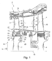
- a high-pressure turbine 1 for an aircraft engine 2 or jet engine which has a stage I rotor device 3 and a downstream in the flow direction 5 of a working gas stage II rotor device 4.
- a turbine nozzle 6 is arranged between the rotor devices 3 and 4.
- the rotor devices 3, 4 each have a disk wheel 7 or 8 and a plurality of circumferentially with the disk wheel 7 and 8 operatively connected turbine blades 9 and 10, wherein the blades 9 and 10 each with a fir-shaped profile 11th or 12 executed blade root 13 and 14 engage in correspondingly profiled disc fingers of the disc wheel 7 and 8 respectively.
- Turbine guide wheel 5 has a multiplicity of turbine guide vanes 17, which are distributed in each case in the circumferential direction U of turbine 1, arranged on a turbine housing 18 of axial-flow turbine 1. Further, the reference numeral 19 designates the axis of rotation of the turbine 1, around which the rotor devices 3, 4 connected to each other in a manner not shown here rotate.
- a so-called internal cooling air flow is fed from a compressor or compressor upstream of the turbine 1.
- cooling air duct 23 which extends completely in the blade root 13 and viewed in the flow direction 5 opens on a rear side 33 of the blade root 13.
- the cooling air duct 23 is connected via a nozzle outlet opening 24 with the intermediate stage space 25 between the two rotor devices 3, 4, which is usually referred to as inter stage cavity, so that through the cooling air duct 23, a part of the cooling air flow, which is supplied to the rotor device 3, in the intermediate stage 25 passes. From here, among other things, it is guided to the rotor blades 10 of the stage II rotor device 4.
- a portion of the intermediate space 25 supplied cooling air flow is - as in Fig. 2 is more apparent - an annular space 26 fed, which is arranged below blade platforms of the blades 9.
- the annular space 26 is limited in the flow direction 5 on the one hand by the rotor device 3 and on the other hand by the turbine nozzle 6.
- feed channels 34, 35 integrated in the blade root 13 can be provided, via which cooling air for swirl reduction can be supplied to the annular space 26.
- annular space 26 In the region of the annular space 26, in the operation of the aircraft engine 2, a pressure is increased by more than 10%, in this case from about 16 bar to 18 bar, compared with conventional designs.
- the annular space 26 in turn is in operative connection with a so-called blocking air ring space 28, which is arranged in the radial direction R of the turbine 1 below an inner wall 29 of the turbine guide vanes 17.
- a portion of the cooling air flow is used as so-called barrier air in the area of the barrier air space 28 for sealing a gap 37 between the blade platforms 27 of the rotor device 3 and the inner wall 29 of the turbine vanes 17, to prevent hot working gas from the Ring channel 20 enters the blocking air space 28.
- the cooling air flow from the blocking air ring space 28 is led in each case via a cooling air passage 30 provided in the region of the inner wall 29 of the turbine nozzle 17 into an interior 31 of the turbine guide vanes 17 and in the present case through an insert 32 for impingement cooling in the direction of a flow direction 5 led rear edge 39 of the turbine guide vanes 17, in the region of the cooling air flow exits through so-called effusion holes or outlet openings from the turbine guide vane 17.
- the positive swirl flow has a swirl number greater than 0.7 in the absolute system in the region of the annular space 26 and a swirl number of greater than 0.5 in the absolute system in the region of the blocking air cavity 28, so that the swirl number is greater than in the region of a region arranged radially outside the turbine vanes , via which the turbine vanes are cooled in conventional designs.
- the cooling air flow enters safely from the blocking air space 28 through the cooling air passage 30 into the interior 31 of the turbine vane 17, wherein in addition to the desired cooling air flow and a blocking air flow through the gap 37 is ensured for all Störszenarien.
- the cooling air passage 30 has a channel geometry that widens in the direction of flow, such as a diffuser, so that a cross-sectional area of the cooling air passage 30 widens, in particular continuously, from an air inlet 40 to an air outlet 41.
- the channel geometry in this case has a curvature, so that a cooling air flow supplied to the cooling air passage 30 is deflected substantially in the radial direction R of the turbine 1.
- the cooling air passage 30 is the cooling air flow guided therein deflecting and slowing down and thus formed pressure increasing.
- a center line 38 of the cooling air passage 30 is substantially rectified to a flow direction of the supplied cooling air flow, wherein the center line 38 extends in the region of the air outlet 41 at least approximately in the radial direction R of the turbine 1, so that the cooling air flow in the region of Cooling air passage 30 is deflected.
- the cooling air flow which has an absolute speed c in the area of the blocking air ring space 28, experiences an increase in pressure in the correspondingly aerodynamically designed cooling air passage 30, which results in a significant pressure gain when exiting the cooling air passage. This pressure increase in turn causes efficient cooling of the turbine vane 17th
- the cooling air flow in the area of the blocking air cavity 28 is illustrated vectorially with a speed triangle.
- w represents the relative velocity of the flow
- c an absolute velocity of the flow
- c r its radial component and u a circumferential velocity.
- the peripheral speed u of each point of the rotor devices 3 and 4 may be 433 m / s and the cooling air flow may be into the cooling air inlet 30 at an absolute speed of 250 m / s occur, wherein the cooling air velocity while increasing the dynamic pressure to z. B. is reduced to 80 m / s.
- Fig. 4A to Fig. 4C show various possible geometries of the cooling air passage 30, wherein an in Fig. 4A in principle, flat NACA inlet, also referred to as Absenkeinlass or "submerged inlet", is most favorable.
- the cooling air inlet is formed in the cooling air passage 30 as a flat introduced into the surface ramp.
- Fig. 4B illustrated NACA inlet with flow-projecting inlet lip and larger air inlet 40 than in the conventional NACA embodiment according to Fig. 4A or an in Fig. 4C illustrated Pitot-type Stirneinlauf with round cross section, which is also referred to as Scoop inlet.
Landscapes
- Engineering & Computer Science (AREA)
- Mechanical Engineering (AREA)
- General Engineering & Computer Science (AREA)
- Turbine Rotor Nozzle Sealing (AREA)
Abstract
Description
- Die Erfindung betrifft eine Turbine, insbesondere eine Hochdruckturbine, für ein Flugtriebwerk, mit in einem Gehäuse angeordneten Turbinenleitschaufeln, gemäß der im Oberbegriff des Patentanspruches 1 näher definierten Art.
- Aus der Praxis sind Hochdruckturbinen von Flugtriebwerken mit umfangsseitig in einem Turbinengehäuse angeordneten Turbinenleitschaufeln bekannt, bei denen die Turbinenleitschaufeln gekühlt werden. Die zusammen ein Turbinenleitrad (NGV) bildenden Turbinenleitschaufeln werden hierzu mit Kühlluft beispielsweise aus einer der letzten Stufen eines Hochdruckkompressors versorgt, wobei die Kühlluft von außen über Rohrleitungen zunächst einem dem Turbinenleitrad zugeordneten Ringraum am Turbinengehäuse zugeführt wird, der in radialer Richtung im Wesentlichen außerhalb der Turbinenleitschaufeln angeordnet ist. Dem Ringraum wird Kühlluft über vereinzelt über den Umfang verteilte Rohrleitungen zugeführt, wobei der Ringraum für jede Turbinenleitschaufel eine Öffnung aufweist, über die Kühlluft in einen Innenraum der Turbinenleitschaufel geleitet wird und über Auslassöffnungen im Bereich einer in axialer Richtung hinteren Kante der Turbinenleitschaufel aus der Turbinenleitschaufel strömt.
- Im Bereich des Ringraums kann es im Betrieb derartiger Flugtriebwerke zu einer Querströmung von Kühlluft in Umfangsrichtung kommen, die nachteilhafterweise eine ungleichförmigen Kühlung der einzelnen Turbinenleitschaufeln zur Folge hat. Zudem wird für die Anordnung der Rohrleitungen zur Führung von Kühlluft von einem Kompressorgehäuse zu dem Turbinengehäuse viel Bauraum benötigt, und die bekannten Lösungen weisen nachteilhafterweise ein unerwünscht hohes Gewicht mit einem entsprechend großen spezifischen Brennstoffverbrauch auf, der wiederum zu einem unerwünscht großen Anteil an Stickoxiden im Abgasstrom führt.
- Weiterhin ist es ein Problem bekannter Ausführungen, dass ein Spalt zwischen dem Turbinenleitrad und in axialer Richtung vor und hinter dem Turbinenleitrad angeordneten Rotorvorrichtungen, durch den zur Abdichtung sogenannte Sperrluft geführt wird, sich hinsichtlich Maß und Form durch die jeweiligen Temperaturausdehnungskoeffizienten in unerwünschter Weise verändert. Die Funktionalität eines Turbinenspaltkontrollsystems bezüglich axialer und radialer Spalte wird hiermit beeinträchtigt.
- Der Erfindung liegt die Aufgabe zugrunde, eine Turbine für ein Flugtriebwerk der eingangs näher bezeichneten Art derart auszubilden, dass auf robuste, kostengünstige und gewichtsoptimierte Weise eine effiziente Kühlung der Turbinenleitschaufeln gewährleistet ist.
- Erfindungsgemäß wird die Aufgabe mit einer gemäß den Merkmalen des Patentanspruchs 1 ausgebildeten Turbine gelöst.
- Es ist mithin eine Turbine, insbesondere eine Hochdruckturbine, für ein Flugtriebwerk vorgesehen, mit einem Gehäuse, an dem umfangsseitig Turbinenleitschaufeln angeordnet sind, wobei die Turbinenleitschaufeln wenigstens einen im Betrieb der Turbine von Kühlluft durchströmten Innenraum aufweisen. Erfindungsgemäß wird vorgeschlagen, dass wenigstens eine Turbinenleitschaufel im Bereich einer in radialer Richtung der Turbine inneren Wandung einen Kühlluftdurchlass aufweist, über den der Innenraum der Turbinenleitschaufel mit Kühlluft zur Kühlung der Turbinenleitschaufel im Betrieb der Turbine versorgbar ist.
- Eine erfindungsgemäß ausgeführte Turbine hat den Vorteil, dass keine äußeren Rohrleitungen zur Versorgung der Turbinenleitschaufeln erforderlich sind, um die Turbinenleitschaufeln im Betrieb der Turbine in gewünschtem Umfang mit Kühlluft zu versorgen. Aus diesem Grund kann die vorgeschlagene Turbine gegenüber einer herkömmlich ausgeführten Turbine mit einer Kühlluftversorgung über äußere Rohrleitungen leichter ausgebildet werden. Zudem sind bei der erfindungsgemäßen Lösung Deckplatten, die bei herkömmlich ausgeführten Turbinen eingesetzt sind, nicht erforderlich.
- Das reduzierte Gewicht führt dazu, dass ein mit der erfindungsgemäßen Turbine ausgeführtes Flugtriebwerk mit einem geringen spezifischen Brennstoffverbrauch betreibbar ist, wodurch ein Abgasstrom einen reduzierten Anteil an Stickoxiden aufweist. Die erfindungsgemäße Turbine ist zudem effizient über eine robuste, nicht störanfällige Gestaltung kühlbar, wodurch die Lebensdauer der Turbine gegenüber bekannten Turbinen erhöht ist.
- Die grundsätzlich stufenunabhängig einsetzbaren Turbinenleitschaufeln der erfindungsgemäßen Turbine werden insbesondere über einen Kühlluftstrom eines sekundären Luftsystems gekühlt, der im Betrieb des Flugtriebwerks vorzugsweise im Bereich einer der letzten Stufen eines Hochdruckkompressors entnommen wird. Der Kühlluftstrom wird dabei insbesondere über einen Ringraum geführt, der unterhalb von Schaufelplattformen einer Rotorvorrichtung angeordnet ist, die in axialer Richtung der Turbine den ein Turbinenleitrad bildenden Turbinenleitschaufeln vorgeordnet sind. Der Ringraum ist in axialer Richtung der Turbine zumindest bereichsweise durch die Rotorvorrichtung und das Turbinenleitrad begrenzt. Von dem Ringraum wird der Kühlluftstrom einem sogenannten Sperrluftringraum zugeführt, der in radialer Richtung der Turbine unterhalb der inneren Wandung der Turbinenleitschaufeln angeordnet ist. Die Druckverhältnisse in dem Kühlluftstrom bzw. der Drall des Kühlluftstroms können dabei derart eingestellt werden, dass neben der Kühlung der Turbinenleitschaufeln auch der Spalt zwischen den Schaufelplattformen der Rotorvorrichtung und der inneren Wandung der Turbinenleitschaufeln abgedichtet wird.
- Die erfindungsgemäße Turbine ist insbesondere bei einer Kühlung der Turbinenleitschaufeln über ein sekundäres Luftsystem geeignet, bei dem im Bereich einer durch einen Scheibenkranz gebildeten Umfangsfläche von Laufschaufeln der Rotorvorrichtung im Bereich von Kühlkanälen keine Abdichtplatten vorgesehen sind. Die zur Kühlung der Turbinenleitschaufeln erforderlichen Druckverhältnisse sind hierbei auf einfache Weise einstellbar.
- Bei einer vorteilhaften Ausführung der erfindungsgemäßen Turbine ist es vorgesehen, dass der Kühlluftdurchlass eine einen Diffusorkanal bildende Geometrie aufweist. Das Vorsehen eines Diffusorkanals mit einer aus der Geometrie resultierenden Strömungsverzögerung bewirkt vorteilhafterweise eine effiziente Turbinenleitschaufelkühlung ohne unerwünscht große Druckverluste. Der durch die Verzögerung erzielbare Druckrückgewinn im Bereich des Kühlluftdurchlasses ermöglicht eine effiziente Innenkühlung der jeweiligen Turbinenleitschaufel, wobei auch in Bereichen mit großem Gegendruck Kühlluft sicher ausgeblasen werden kann. Die Lebensdauer der Turbine kann hierdurch vorteilhafterweise weiter erhöht werden.
- Der einen Diffusorkanal bildende Kühlluftdurchlass weist vorzugsweise eine sich in Strömungsrichtung diffusorartig erweiternde Querschnittsfläche auf, wobei hierdurch auf konstruktiv einfache Weise ein Verzögerungskanal geschaffen ist.
- Bei einer vorteilhaften Gestaltung des Kühlluftdurchlasses ist dessen Mittellinie ausgehend von einem Lufteinlass in Richtung eines Luftauslasses gekrümmt, wobei die Mittellinie im Bereich des Luftauslasses im Wesentlichen in radialer Richtung der Turbine verläuft. Hierdurch wird eine Strömungsgeschwindigkeit eines Kühlluftstroms im Bereich des Kühlluftdurchlasses verlangsamt und der statische Druck stetig erhöht, was letztlich zu einer verbesserten Kühlung der Turbinenleitschaufeln führt.
- Die geometrische Gestaltung des Lufteinlasses erfolgt zweckmäßigerweise in einer Weise, dass die aerodynamische Eintrittsfläche im Auslegungspunkt auf die Absolutgeschwindigkeit der Anströmung optimiert ist, so dass eine weitestgehend verlustfreie Einströmung in den Kühlluftdurchlass erfolgen kann. Der Kühlluftdurchlass wird somit im Bereich des Lufteinlasses in gewünschtem Umfang zur im Betrieb der Turbine vorliegenden Drallströmung angestellt, so dass der Kühlluftstrom mit möglichst wenig Druckverlust in den Kühlluftdurchlass eintritt und eine größtmögliche Effizienz erzielt wird. Die Mittellinie des Kühlluftdurchlasses erstreckt sich hierfür im Bereich des Lufteinlasses in eine Richtung, die wenigstens annähernd gleichgerichtet zur Kühlluftanströmrichtung ist.
- Bei einer vorteilhaften Ausführung der erfindungsgemäßen Turbine ist es vorgesehen, dass der Kühlluftdurchlass im Bereich des Lufteinlasses in Umfangsrichtung der Turbine von zwei Seitenfläche begrenzt ist, deren Abstand sich in Umfangsrichtung der Turbine ausgehend von dem Lufteinlass in Richtung eines Luftauslasses vergrößert. Hierbei wird eine dem Kühlluftdurchlass zugeführte Strömung vorteilhafterweise lediglich in geringem Umfang gestört. Zwischen den Seitenflächen kann der Lufteinlass dabei insbesondere von einem rampenförmig ausgeführten Bereich der inneren Wandung gebildet sein.
- Der Kühllufteinlass ist vorzugsweise als sogenannter flacher NACA-Einlass ausgeführt. Alternativ oder zusätzlich hierzu kann der Kühlluftdurchlass im Bereich des Lufteinlasses eine Einlauflippe aufweisen, die insbesondere als bereichsweise Vorkragung in radialer und/oder axialer Richtung der Turbine über die innere Wandung der Turbinenleitschaufel hinausragt und somit im Betrieb der Turbine entgegen einer Strömung ragt.
- Bei einer vorteilhaften Ausführung der Erfindung kann der Lufteinlass des Kühlluftdurchlasses auch einen Stirneinlauf bilden, wobei der Lufteinlass vorzugsweise Pitot-artig ausgeführt ist.
- Der Kühlluftdurchlass ist vorzugsweise in der Art eines sogenannten Scoop ausgeführt, jedoch kann der Fachmann je nach Anwendungsfall auch kürzere Formen, z. B. in der Art eines Semi-Scoop, wählen.
- Die Kühlluftführung im Innenraum der Turbinenleitschaufel kann prinzipiell beliebig ausgeführt sein, wobei in einer vorteilhaften Ausführung ein Einsatz zur Prallkühlung im Innenraum der Turbinenleitschaufel angeordnet sein kann, dem im Betrieb der Turbine ein Kühlluftstrom durch den Kühlluftdurchlass zuführbar ist. Der Einsatz kann hierbei mehrere Kühlauslässe aufweisen, über die der Kühlluftstrom im Bereich einer Hinterkante der Turbinenleitschaufel aus der Turbinenleitschaufel ableitbar ist.
- Um auf einfache Weise einen zur Kühlung der Turbinenleitschaufeln ausreichenden Druck, der sich aus einer statischen Komponente und einer dynamischen Drallkomponente zusammensetzt, zu erzielen, ist bei einer vorteilhaften Ausführung der erfindungsgemäßen Turbine stromauf der Turbinenleitschaufeln eine Rotorvorrichtung wie z. B. ein Stufe-I-Rotor, angeordnet, wobei Schaufelfüße von Laufschaufeln dieser Rotorvorrichtung wenigstens einen Durchlass zur Führung eines Kühlluftstroms in einen Ringraum vor dem Kühlluftdurchlass aufweisen. Die beispielsweise als Mikroturbinen ausgeführten Durchlässe können sich dabei im Wesentlichen in axialer Richtung der Turbine erstrecken.
- Die Schaufelfüße der Laufschaufeln können neben wenigstens einem solchen Durchlass weiterhin wenigstens einen zusätzlichen Kanal zur Führung eines Kühlluftstroms in axialer Richtung der Turbine durch die Schaufelfüße aufweisen, wobei ein solcher Kanal wiederum eine Mikroturbine darstellen kann und vorzugsweise einen sogenannten Drallreduzierkanal bildet, mittels dem im Betrieb des Flugtriebwerks gewünschte Druckverhältnisse im Ringraum bzw. im Sperrluftringraum auf einfache Weise erzielbar sind.
- Neben den genannten Merkmalskombinationen sind sowohl die in den Patentansprüchen angegebenen Merkmale als auch die in dem nachfolgenden Ausführungsbeispiel angegebenen Merkmale jeweils für sich alleine oder in beliebiger Kombination miteinander geeignet, den erfindungsgemäßen Gegenstand auszubilden.
- Weitere Vorteile und Ausführungsmöglichkeiten der erfindungsgemäßen Turbine ergeben sich ebenfalls aus den Patentansprüchen und dem nachfolgenden unter Bezugnahme auf die Zeichnung prinzipmäßig beschriebenen Ausführungsbeispiel.
- Es zeigt:
- Fig. 1
- einen Teil-Längsschnitt durch eine zweistufige HochdruckTurbine, wobei an einem Turbinengehäuse angeordnete Turbinenleitschaufeln ersichtlich sind,
- Fig. 2
- eine vereinfachte Ansicht eines Ausschnitts der
Fig. 1 , wobei ein Kühlluftdurchlass näher ersichtlich ist, über den einem Innenraum einer Turbinenleitschaufel Kühlluft zuführbar ist; - Fig. 3
- eine Schnittansicht gemäß der Linie A-A in
Fig. 2 ; - Fig. 4A
- eine prinzipmäßige Darstellung einer ersten geometrischen Ausführungsvariante des Kühlluftdurchlasses der
Fig. 1 bis Fig. 3 als so genannter NACA-Einlass; - Fig. 4B
- eine prinzipmäßige Darstellung einer zweiten geometrischen Ausführungsvariante des Kühlluftdurchlasses der
Fig. 1 bis Fig. 3 als NACA-Einlass mit in die Strömung ausragender Einlauflippe; und - Fig. 4C
- eine prinzipmäßige Darstellung einer dritten geometrischen Ausführungsvariante des Kühlluftdurchlasses der
Fig. 1 bis Fig. 3 als Pitot-artiger Stirneinlauf. - Bezug nehmend auf
Fig. 1 bis Fig. 3 sind jeweils unterschiedliche Ausschnitte einer Hochdruck-Turbine 1 für ein Flugtriebwerk 2 bzw. Strahltriebwerk ersichtlich, welches eine Stufe-I-Rotorvorrichtung 3 und eine in Strömungsrichtung 5 eines Arbeitsgases nachgelagerte Stufe-II-Rotorvorrichtung 4 aufweist. In axialer Richtung A der Turbine 1 ist zwischen den Rotorvorrichtungen 3 und 4 ein Turbinenleitrad 6 angeordnet. - Die Rotorvorrichtungen 3, 4 weisen jeweils ein Scheibenrad 7 bzw. 8 und eine Vielzahl von umfangsseitig mit dem Scheibenrad 7 bzw. 8 wirkverbundenen Turbinen-Laufschaufeln 9 bzw. 10 auf, wobei die Laufschaufeln 9 bzw. 10 jeweils mit einem mit einem tannenbaumförmigen Profil 11 bzw. 12 ausgeführten Schaufelfuß 13 bzw. 14 in entsprechend profilierte Scheibenfinger des Scheibenrads 7 bzw. 8 eingreifen. Gegen eine axiale Verschiebung sind die Laufschaufeln 9 bzw. 10 durch einen geeignet gestalteten und an der Rotorscheibe bzw. dem Scheibenrad 7 bzw. 8 befestigten Schließring 15 bzw. eine Schließplatte 16 gesichert.
- Das Turbinenleitrad 5 weist eine Vielzahl von Turbinenleitschaufeln 17 auf, die jeweils in Umfangsrichtung U der Turbine 1 verteilt an einem Turbinengehäuse 18 der Axial-Turbine 1 angeordnet sind. Ferner ist mit der Bezugsziffer 19 die Rotationsachse der Turbine 1 bezeichnet, um welche die miteinander auf hier nicht dargestellte Weise verbundenen Rotorvorrichtungen 3, 4 rotieren.
- Im Bereich eines Ringkanals 20, in den sowohl die Laufschaufeln 9, 10 der Rotorvorrichtungen 3, 4 als auch die Turbinenleitschaufeln 17 des Turbinenleitrades 6 hineinragen, strömt im Betrieb des Flugtriebwerks in Strömungsrichtung 5 das Arbeitsgas. Aufgrund der hohen Temperaturen des Arbeitsgases werden vorliegend sowohl die Laufschaufeln 9, 10 als auch die Turbinenleitschaufeln 17 luftgekühlt.
- Zur Kühlung wird insbesondere Kühlluftstrom eines sekundären Luftsystems, ein sogenannter interner Kühlluftstrom, von einem der Turbine 1 vorgeschalteten Verdichter bzw. Kompressor zugeführt. Dabei wird der Kühlluftstrom über einen in dem Scheibenrad 7 verlaufenden Versorgungskanal 21, der bezogen auf die Strömungsrichtung 5 im Bereich einer vorderen Stirnseite des Scheibenrads 8 mündet, einer Kühlluftkammer 22 zugeführt, die in Wirkverbindung mit nicht näher ersichtliche Kühlkanäle im Inneren der Laufschaufeln 9, 10 steht.
- Von der Kühlluftkammer 22 zweigt zusätzlich ein weiterer Kühlluftkanal bzw. Durchlass 23 ab, der vollständig im Schaufelfuß 13 verläuft und in Strömungsrichtung 5 betrachtet auf einer Rückseite 33 des Schaufelfußes 13 mündet. Der Kühlluftkanal 23 ist über eine Düsenaustrittsöffnung 24 mit dem Zwischenstufenraum 25 zwischen den beiden Rotorvorrichtungen 3, 4, welcher meist als Inter Stage Cavity bezeichnet wird, verbunden, so dass durch den Kühlluftkanal 23 ein Teil des Kühlluftstromes, der der Rotorvorrichtung 3 zugeführt wird, in den Zwischenstufenraum 25 gelangt. Von hier wird er unter anderem an die Laufschaufeln 10 der Stufe-II-Rotorvorrichtung 4 geführt.
- Ein Teil des dem Zwischenstufenraum 25 zugeführten Kühlluftstroms wird - wie in
Fig. 2 näher ersichtlich ist - einem Ringraum 26 zugeführt, der unterhalb von Schaufelplattformen der Laufschaufeln 9 angeordnet ist. Der Ringraum 26 ist in Strömungsrichtung 5 einerseits durch die Rotorvorrichtung 3 und andererseits durch das Turbinenleitrad 6 begrenzt. - Daneben können optional zwei in den Schaufelfuß 13 integrierte Zuführkanäle 34, 35 vorgesehen sein, über die dem Ringraum 26 Kühlluft zur Drallreduzierung zuführbar ist.
- Im Bereich des Ringraums 26 ist im Betrieb des Flugtriebwerks 2 ein Druck gegenüber herkömmlichen Ausführungen um insbesondere mehr als 10 %, vorliegend von etwa 16 bar auf 18 bar erhöht. Der Ringraum 26 steht wiederum in Wirkverbindung mit einem sogenannten Sperrluftringraum 28, der in radialer Richtung R der Turbine 1 unterhalb einer inneren Wandung 29 der Turbinenleitschaufeln 17 angeordnet ist.
- Neben der Kühlung der Turbinenleitschaufeln 17 wird ein Teil des Kühlluftstroms als sogenannte Sperrluft im Bereich des Sperrluftringraum 28 zur Abdichtung eines Spalts 37 zwischen den Schaufelplattformen 27 der Rotorvorrichtung 3 und der inneren Wandung 29 der Turbinenleitschaufeln 17 verwendet, um zu verhindern, dass heißes Arbeitsgas von dem Ringkanal 20 in den Sperrluftringraum 28 eintritt.
- Zur Kühlung der Turbinenleitschaufeln 17 wird der Kühlluftstrom aus dem Sperrluftringraum 28 jeweils über einen im Bereich der inneren Wandung 29 des Turbinenleitrades 17 vorgesehenen Kühlluftdurchlass 30 in einen Innenraum 31 der Turbinenleitschaufeln 17 geleitet und vorliegend durch einen Einsatz 32 zur Prallkühlung in Richtung einer bezüglich der Strömungsrichtung 5 hinteren Kante 39 der Turbinenleitschaufeln 17 geleitet, in deren Bereich der Kühlluftstrom durch sogenannte Effusionslöchern bzw. Austrittsöffnungen aus der Turbinenleitschaufel 17 austritt.
- Wie in der Darstellung gemäß
Fig. 3 näher ersichtlich ist, weist der dem Kühlluftdurchlass 30 zugeführte Kühlluftstrom bezogen auf die mit Pfeil ω gezeigte Drehrichtung der Rotorvorrichtungen 3, 4 einen positiven Drall auf. Die positive Drallströmung hat im Bereich des Ringraums 26 eine Drallzahl von größer 0,7 im Absolutsystem und im Bereich des Sperrluftringraums 28 eine Drallzahl von größer 0,5 im Absolutsystem, so dass die Drallzahl größer ist als im Bereich eines radial außerhalb der Turbinenleitschaufeln angeordneten Bereiches, über den die Turbinenleitschaufeln bei herkömmlichen Ausführungen gekühlt werden. - Aufgrund der mit der beschriebenen Konstruktion erzielbaren Drallzahlen tritt der Kühlluftstrom auf sichere Weise aus dem Sperrluftringraum 28 durch den Kühlluftdurchlass 30 in den Innenraum 31 der Turbinenleitschaufel 17 ein, wobei neben der gewünschten Kühlluftströmung auch eine Sperrluftströmung durch den Spalt 37 für sämtliche Störszenarien sichergestellt ist.
- Zur Bildung eines Diffusorkanals weist der Kühlluftdurchlass 30 eine sich in Strömungsrichtung wie ein Diffusor erweiternde Kanalgeometrie auf, so dass sich eine Querschnittsfläche des Kühlluftdurchlasses 30 ausgehend von einem Lufteinlass 40 bis zu einem Luftauslass 41 insbesondere kontinuierlich erweitert. Die Kanalgeometrie weist dabei eine Krümmung auf, so dass ein dem Kühlluftdurchlass 30 zugeführter Kühlluftstrom im Wesentlichen in radialer Richtung R der Turbine 1 umgelenkt wird. Wie insbesondere in den
Fig. 2 und Fig. 3 ersichtlich, ist der Kühlluftdurchlass 30 den darin geführten Kühlluftstrom umlenkend sowie verlangsamend und damit druckerhöhend ausgebildet. - Im Bereich des Lufteinlasses 40 ist eine Mittellinie 38 des Kühlluftdurchlasses 30 im Wesentlichen gleichgerichtet zu einer Strömungsrichtung des zugeführten Kühlluftstroms, wobei sich die Mittellinie 38 im Bereich des Luftauslasses 41 wenigstens annähernd in radialer Richtung R der Turbine 1 erstreckt, so dass der Kühlluftstrom im Bereich des Kühlluftdurchlasses 30 umgelenkt wird.
- Der Kühlluftstrom, welcher im Bereich des Sperrluftringraums 28 eine Absolutgeschwindigkeit c aufweist, erfährt in dem entsprechend aerodynamisch ausgelegten Kühlluftdurchlass 30 eine Druckerhöhung, was in einem signifikanten Druckgewinn bei Austritt aus dem Kühlluftdurchlass resultiert. Diese Druckerhöhung bewirkt wiederum eine effiziente Kühlung der Turbinenleitschaufel 17.
- In der Schnittansicht gemäß
Fig. 3 ist der Kühlluftstrom im Bereich des Sperrluftringraums 28 vektoriell mit einem Geschwindigkeitsdreieck veranschaulicht. Darin ist mit w die Relativgeschwindigkeit der Strömung, mit c eine Absolutgeschwindigkeit der Strömung und mit cr deren Radialkomponente und u eine Umfangsgeschwindigkeit dargestellt. Die Umfangsgeschwindigkeit u jeden Punktes der Rotorvorrichtungen 3 bzw. 4 kann beispielsweise 433 m/s betragen und die Kühlluftströmung mit einer Absolutgeschwindigkeit von 250 m/s in den Kühllufteinlass 30 eintreten, worin die Kühlluftgeschwindigkeit unter Erhöhung des Staudrucks auf z. B. auf 80 m/s reduziert wird. - Die
Fig. 4A bis Fig. 4C zeigen verschiedene mögliche Geometrien des Kühlluftdurchlasses 30, wobei ein inFig. 4A prinzipmäßig dargestellter flacher NACA-Einlass, auch als Absenkeinlass oder "submerged inlet" bezeichnet, am günstigsten ist. Dabei ist der Kühllufteintritt in den Kühlluftdurchlass 30 als eine flache in die Oberfläche eingebrachte Rampe ausgebildet. - Je nach Eigenart der Konstruktion des Turbinenleitrads 6 und der Bestandteile des Ringraumes 26 sowie des Sperrluftringraumes 28 können auch andere Einlaufgeometrien von Vorteil sein, wie ein in
Fig. 4B dargestellter NACA-Einlass mit in die Strömung ausragender Einlauflippe und größerem Lufteinlass 40 als bei der konventionellen NACA-Ausführung gemäßFig. 4A oder ein inFig. 4C dargestellter Pitot-artiger Stirneinlauf mit rundem Querschnitt, welcher auch als Scoop-Einlass bezeichnet wird. -
- 1
- Turbine
- 2
- Flugtriebwerk
- 3
- Stufe-I-Rotorvorrichtung
- 4
- Stufe-II-Rotorvorrichtung
- 5
- Strömungsrichtung
- 6
- Turbinenleitrad
- 7
- Scheibenrad
- 8
- Scheibenrad
- 9
- Laufschaufel
- 10
- Laufschaufel
- 11
- tannenbaumförmiges Profil
- 12
- tannenbaumförmiges Profil
- 13
- Schaufelfuß
- 14
- Schaufelfuß
- 15
- Schließring
- 16
- Schließplatte
- 17
- Turbinenleitschaufel
- 18
- Turbinengehäuse
- 19
- Rotationsachse
- 20
- Ringkanal
- 21
- Versorgungskanal
- 22
- Kühlluftkammer
- 23
- Kühlluftkanal
- 24
- Düsenaustrittsöffnung
- 25
- Zwischenstufenraum
- 26
- Ringraum
- 27
- Schaufelplattform
- 28
- Sperrluftringraum
- 29
- innere Wandung der Turbinenleitschaufel
- 30
- Kühlluftdurchlass, Diffusorkanal
- 31
- Innenraum der Turbinenleitschaufel
- 32
- Einsatz zur Prallkühlung
- 33
- Rückseite des Schaufelfußes
- 34
- Zuführkanal
- 35
- Zuführkanal
- 37
- Spalt
- 38
- Mittellinie des Kühlluftdurchlasses
- 39
- hintere Kante der Turbinenleitschaufel
- 40
- Lufteinlass des Kühlluftdurchlasses
- 41
- Luftauslass des Kühlluftdurchlasses
- R
- radiale Richtung
- U
- Umfangsrichtung
- c
- Absolutgeschwindigkeit
- cr
- Radialkomponente
- u
- Umfangsgeschwindigkeit
- w
- Relativgeschwindigkeit
- ω
- Rotationsgeschwindigkeit
Claims (11)
- Turbine (1), insbesondere Hochdruckturbine, für ein Flugtriebwerk (2) mit einem Gehäuse (18) an dem umfangsseitig Turbinenleitschaufeln (17) angeordnet sind, wobei die Turbinenleitschaufeln (17) wenigstens einen im Betrieb der Turbine (1) von Kühlluft durchströmten Innenraum (31) aufweisen, dadurch gekennzeichnet, dass wenigstens eine Turbinenleitschaufel (17) im Bereich einer in radialer Richtung (R) der Turbine (1) inneren Wandung (29) einen Kühlluftdurchlass (30) aufweist, über den der Innenraum (31) der Turbinenleitschaufel (17) mit Kühlluft versorgbar ist.
- Turbine nach Anspruch 1, dadurch gekennzeichnet, dass der Kühlluftdurchlass (30) eine einen Diffusorkanal bildende Geometrie aufweist.
- Turbine nach einem der Ansprüche 1 oder 2, dadurch gekennzeichnet, dass der Kühlluftdurchlass (30) eine sich in Strömungsrichtung (5) diffusorartig erweiternde Querschnittsfläche aufweist.
- Turbine nach einem der Ansprüche 1 bis 3, dadurch gekennzeichnet, dass eine Mittellinie (38) des Kühlluftdurchlasses (30) ausgehend von einem Lufteinlass (40) in Richtung eines Luftauslasses (41) gekrümmt ist, wobei die Mittellinie (38) im Bereich des Luftauslasses (41) im Wesentlichen in radialer Richtung (R) der Turbine (1) verläuft.
- Turbine nach einem der Ansprüche 1 bis 4, dadurch gekennzeichnet, dass der Kühlluftdurchlass (30) im Bereich eines Lufteinlasses (40) in Umfangsrichtung (U) der Turbine (1) von zwei Seitenfläche begrenzt ist, deren Abstand sich in Umfangsrichtung (U) der Turbine (1) ausgehend von dem Lufteinlass (40) in Richtung eines Luftauslasses (41) vergrößert.
- Turbine nach einem der Ansprüche 1 bis 5, dadurch gekennzeichnet, dass ein Lufteinlass (40) des Kühlluftdurchlasses (30) als NACA-förmiger Einlass ausgebildet ist.
- Turbine nach einem der Ansprüche 1 bis 6, dadurch gekennzeichnet, dass ein Lufteinlass (40) des Kühlluftdurchlasses (30) mit einer Einlauflippe ausgebildet ist.
- Turbine nach einem der Ansprüche 1 bis 7, dadurch gekennzeichnet, dass ein Lufteinlass (40) des Kühlluftdurchlasses (30) einen Stirneinlauf bildet.
- Turbine nach einem der Ansprüche 1 bis 8, dadurch gekennzeichnet, dass im Innenraum (31) der Turbinenleitschaufel (17) ein Einsatz (32) zur Prallkühlung angeordnet ist.
- Turbine nach einem der Ansprüche 1 bis 9, dadurch gekennzeichnet, dass stromauf der Turbinenleitschaufeln (17) eine Rotorvorrichtung (3) angeordnet ist, wobei Schaufelfüße (13) von Laufschaufeln (9) dieser Rotorvorrichtung (3) einen Durchlass (23) zur Führung eines Kühlluftstroms in einen mit Drallströmung beaufschlagten Ringraum (26, 28, 37) vor dem Kühlluftdurchlass (30) aufweisen.
- Turbine nach Anspruch 10, dadurch gekennzeichnet, dass die Schaufelfüße (13) der Laufschaufeln (9) wenigstens einen zusätzlichen Zuführkanal (34, 35) zur Führung eines Kühlluftstroms aufweisen.
Applications Claiming Priority (1)
| Application Number | Priority Date | Filing Date | Title |
|---|---|---|---|
| DE102015111843.2A DE102015111843A1 (de) | 2015-07-21 | 2015-07-21 | Turbine mit gekühlten Turbinenleitschaufeln |
Publications (2)
| Publication Number | Publication Date |
|---|---|
| EP3121371A1 true EP3121371A1 (de) | 2017-01-25 |
| EP3121371B1 EP3121371B1 (de) | 2020-10-28 |
Family
ID=56296506
Family Applications (1)
| Application Number | Title | Priority Date | Filing Date |
|---|---|---|---|
| EP16175769.5A Active EP3121371B1 (de) | 2015-07-21 | 2016-06-22 | Turbine mit gekühlten turbinenleitschaufeln |
Country Status (3)
| Country | Link |
|---|---|
| US (1) | US10378372B2 (de) |
| EP (1) | EP3121371B1 (de) |
| DE (1) | DE102015111843A1 (de) |
Cited By (1)
| Publication number | Priority date | Publication date | Assignee | Title |
|---|---|---|---|---|
| US12624639B2 (en) | 2024-07-26 | 2026-05-12 | MTU Aero Engines AG | Turbine module for a turbomachine |
Families Citing this family (8)
| Publication number | Priority date | Publication date | Assignee | Title |
|---|---|---|---|---|
| US9920652B2 (en) * | 2015-02-09 | 2018-03-20 | United Technologies Corporation | Gas turbine engine having section with thermally isolated area |
| DE102016104957A1 (de) * | 2016-03-17 | 2017-09-21 | Rolls-Royce Deutschland Ltd & Co Kg | Kühleinrichtung zur Kühlung von Plattformen eines Leitschaufelkranzes einer Gasturbine |
| DE102018206259A1 (de) * | 2018-04-24 | 2019-10-24 | MTU Aero Engines AG | Leitschaufel für eine turbine einer strömungsmaschine |
| FR3085420B1 (fr) * | 2018-09-04 | 2020-11-13 | Safran Aircraft Engines | Disque de rotor avec arret axial des aubes, ensemble d'un disque et d'un anneau et turbomachine |
| US11047247B2 (en) * | 2018-12-21 | 2021-06-29 | Rolls-Royce Plc | Turbine section of a gas turbine engine with ceramic matrix composite vanes |
| GB202005789D0 (en) | 2020-03-03 | 2020-06-03 | Itp Next Generation Turbines S L U | Blade assembly for gas turbine engine |
| CN114198153B (zh) * | 2020-09-17 | 2024-05-03 | 中国航发商用航空发动机有限责任公司 | 涡轮叶片冷却系统及航空发动机 |
| ES3037032T3 (en) | 2021-07-21 | 2025-09-26 | MTU Aero Engines AG | A turbine module for a turbomachine and use of this module |
Citations (7)
| Publication number | Priority date | Publication date | Assignee | Title |
|---|---|---|---|---|
| DE2065334A1 (de) * | 1969-12-01 | 1973-04-26 | Gen Electric | Schaufelanordnung mit kuehlvorrichtung |
| US3791758A (en) * | 1971-05-06 | 1974-02-12 | Secr Defence | Cooling of turbine blades |
| EP1004748A2 (de) * | 1998-11-27 | 2000-05-31 | Rolls-Royce Deutschland GmbH | Rotor einer Strömungsmaschine |
| EP1013882A2 (de) * | 1998-12-24 | 2000-06-28 | Rolls-Royce Plc | Kühlluftführung in einer Gasturbine |
| EP1921270A2 (de) * | 2006-11-10 | 2008-05-14 | General Electric Company | Verbundtriebwerk mit gekühlten Leitschaufeln |
| US7921654B1 (en) * | 2007-09-07 | 2011-04-12 | Florida Turbine Technologies, Inc. | Cooled turbine stator vane |
| EP2725191A1 (de) * | 2012-10-23 | 2014-04-30 | Alstom Technology Ltd | Gasturbine und Turbinenschaufel für solch eine Gasturbine |
Family Cites Families (10)
| Publication number | Priority date | Publication date | Assignee | Title |
|---|---|---|---|---|
| US3291447A (en) | 1965-02-15 | 1966-12-13 | Gen Electric | Steam turbine rotor cooling |
| US4666368A (en) * | 1986-05-01 | 1987-05-19 | General Electric Company | Swirl nozzle for a cooling system in gas turbine engines |
| US4820116A (en) * | 1987-09-18 | 1989-04-11 | United Technologies Corporation | Turbine cooling for gas turbine engine |
| ES2261288T3 (es) * | 2001-03-26 | 2006-11-16 | Siemens Aktiengesellschaft | Turbina de gas. |
| ES2288687T3 (es) * | 2003-07-04 | 2008-01-16 | Siemens Aktiengesellschaft | Componente de refrigeracion abierta para una turbina de gas, camara de combustion y turbina de gas. |
| FR2872541B1 (fr) | 2004-06-30 | 2006-11-10 | Snecma Moteurs Sa | Aube fixe de turbine a refroidissement ameliore |
| GB2467790B (en) * | 2009-02-16 | 2011-06-01 | Rolls Royce Plc | Vane |
| EP2423435A1 (de) * | 2010-08-30 | 2012-02-29 | Siemens Aktiengesellschaft | Schaufel für eine Turbomaschine |
| EP2626519A1 (de) * | 2012-02-09 | 2013-08-14 | Siemens Aktiengesellschaft | Turbinenbaugruppe, zugehöriges Prallkühlungsrohr und Gasturbinenkraftwerk. |
| US9482100B2 (en) * | 2012-02-15 | 2016-11-01 | United Technologies Corporation | Multi-lobed cooling hole |
-
2015
- 2015-07-21 DE DE102015111843.2A patent/DE102015111843A1/de not_active Withdrawn
-
2016
- 2016-06-22 EP EP16175769.5A patent/EP3121371B1/de active Active
- 2016-07-21 US US15/215,726 patent/US10378372B2/en active Active
Patent Citations (7)
| Publication number | Priority date | Publication date | Assignee | Title |
|---|---|---|---|---|
| DE2065334A1 (de) * | 1969-12-01 | 1973-04-26 | Gen Electric | Schaufelanordnung mit kuehlvorrichtung |
| US3791758A (en) * | 1971-05-06 | 1974-02-12 | Secr Defence | Cooling of turbine blades |
| EP1004748A2 (de) * | 1998-11-27 | 2000-05-31 | Rolls-Royce Deutschland GmbH | Rotor einer Strömungsmaschine |
| EP1013882A2 (de) * | 1998-12-24 | 2000-06-28 | Rolls-Royce Plc | Kühlluftführung in einer Gasturbine |
| EP1921270A2 (de) * | 2006-11-10 | 2008-05-14 | General Electric Company | Verbundtriebwerk mit gekühlten Leitschaufeln |
| US7921654B1 (en) * | 2007-09-07 | 2011-04-12 | Florida Turbine Technologies, Inc. | Cooled turbine stator vane |
| EP2725191A1 (de) * | 2012-10-23 | 2014-04-30 | Alstom Technology Ltd | Gasturbine und Turbinenschaufel für solch eine Gasturbine |
Cited By (1)
| Publication number | Priority date | Publication date | Assignee | Title |
|---|---|---|---|---|
| US12624639B2 (en) | 2024-07-26 | 2026-05-12 | MTU Aero Engines AG | Turbine module for a turbomachine |
Also Published As
| Publication number | Publication date |
|---|---|
| US20170022836A1 (en) | 2017-01-26 |
| DE102015111843A1 (de) | 2017-01-26 |
| EP3121371B1 (de) | 2020-10-28 |
| US10378372B2 (en) | 2019-08-13 |
Similar Documents
| Publication | Publication Date | Title |
|---|---|---|
| EP3121371B1 (de) | Turbine mit gekühlten turbinenleitschaufeln | |
| EP3121372A1 (de) | Gekühltes turbinenlaufrad für ein flugtriebwerk | |
| EP3059433B1 (de) | Gasturbinentriebwerk mit ölkühler in der triebwerksverkleidung | |
| EP1004748B1 (de) | Laufrad für eine Strömungsmaschine | |
| EP3093447B1 (de) | Rotor einer turbine einer gasturbine mit verbesserter kühlluftführung | |
| EP3121373B1 (de) | Gekühltes turbinenlaufrad, insbesondere für ein flugtriebwerk | |
| EP3219918B1 (de) | Gasturbine mit einer kühleinrichtung zur kühlung von plattformen eines leitschaufelkranzes der gasturbine | |
| EP2818724B1 (de) | Strömungsmaschine und Verfahren | |
| EP3290644B1 (de) | Gasturbine | |
| DE112015003934T5 (de) | Gasturbine | |
| EP3155227B1 (de) | Turbinenschaufel | |
| DE102016115610A1 (de) | Gasturbine und Verfahren zum Aufhängen eines Turbinen-Leitschaufelsegments einer Gasturbine | |
| CH709266A2 (de) | Turbinenschaufel und Verfahren zum Auswuchten eines Spitzendeckbandes einer Turbinenschaufel und Gasturbine. | |
| DE102016124806A1 (de) | Turbinen-Laufschaufelanordnung für eine Gasturbine und Verfahren zum Bereitstellen von Dichtluft in einer Turbinen-Laufschaufelanordnung | |
| DE102007050916A1 (de) | Verfahren und Vorrichtung zum Zusammenbau von Gasturbinen-Triebwerken | |
| EP3462090A1 (de) | Düse mit axialer verlängerung für eine brennkammer eines triebwerks | |
| EP3109410B1 (de) | Statorvorrichtung für eine strömungsmaschine mit einer gehäuseeinrichtung und mehreren leitschaufeln | |
| WO2013107489A1 (de) | Verfahren und vorrichtung zur stabilisierung eines verdichterstroms | |
| DE112017002151B4 (de) | Verdichterdiffusor und gasturbine | |
| DE102013209746B4 (de) | Turbinenstufe mit einer Ausblasanordnung und Verfahren zum Ausblasen einer Sperrgasströmung | |
| EP3682119A1 (de) | Diffusor für einen radialverdichter | |
| CH701151B1 (de) | Turbomaschine mit einem Verdichterradelement. | |
| EP2725203B1 (de) | Kühlluftführung in einer Gehäusestruktur einer Strömungsmaschine | |
| EP3327258A1 (de) | Eintrittsleitrad für eine turbomaschine | |
| EP3109408A1 (de) | Statorvorrichtung für eine strömungsmaschine mit einer gehäuseeinrichtung und mehreren leitschaufeln |
Legal Events
| Date | Code | Title | Description |
|---|---|---|---|
| PUAI | Public reference made under article 153(3) epc to a published international application that has entered the european phase |
Free format text: ORIGINAL CODE: 0009012 |
|
| STAA | Information on the status of an ep patent application or granted ep patent |
Free format text: STATUS: THE APPLICATION HAS BEEN PUBLISHED |
|
| AK | Designated contracting states |
Kind code of ref document: A1 Designated state(s): AL AT BE BG CH CY CZ DE DK EE ES FI FR GB GR HR HU IE IS IT LI LT LU LV MC MK MT NL NO PL PT RO RS SE SI SK SM TR |
|
| AX | Request for extension of the european patent |
Extension state: BA ME |
|
| RIN1 | Information on inventor provided before grant (corrected) |
Inventor name: LEHMANN, KNUT, DR. Inventor name: NEGULESCU, JOANA Inventor name: TAEGE, JENS Inventor name: NEGULESCU, DIMITRIE, DR. |
|
| RIN1 | Information on inventor provided before grant (corrected) |
Inventor name: LEHMANN, KNUT, DR. Inventor name: NEGULESCU, DIMITRIE, DR. Inventor name: NEGULESCU, JOANA Inventor name: TAEGE, JENS |
|
| STAA | Information on the status of an ep patent application or granted ep patent |
Free format text: STATUS: REQUEST FOR EXAMINATION WAS MADE |
|
| 17P | Request for examination filed |
Effective date: 20170725 |
|
| RBV | Designated contracting states (corrected) |
Designated state(s): AL AT BE BG CH CY CZ DE DK EE ES FI FR GB GR HR HU IE IS IT LI LT LU LV MC MK MT NL NO PL PT RO RS SE SI SK SM TR |
|
| STAA | Information on the status of an ep patent application or granted ep patent |
Free format text: STATUS: EXAMINATION IS IN PROGRESS |
|
| 17Q | First examination report despatched |
Effective date: 20180604 |
|
| GRAP | Despatch of communication of intention to grant a patent |
Free format text: ORIGINAL CODE: EPIDOSNIGR1 |
|
| STAA | Information on the status of an ep patent application or granted ep patent |
Free format text: STATUS: GRANT OF PATENT IS INTENDED |
|
| INTG | Intention to grant announced |
Effective date: 20200608 |
|
| RIN1 | Information on inventor provided before grant (corrected) |
Inventor name: NEGULESCU, JOANA Inventor name: NEGULESCU, DIMITRIE Inventor name: LEHMANN, KNUT Inventor name: TAEGE, JENS |
|
| GRAS | Grant fee paid |
Free format text: ORIGINAL CODE: EPIDOSNIGR3 |
|
| GRAA | (expected) grant |
Free format text: ORIGINAL CODE: 0009210 |
|
| STAA | Information on the status of an ep patent application or granted ep patent |
Free format text: STATUS: THE PATENT HAS BEEN GRANTED |
|
| RIN1 | Information on inventor provided before grant (corrected) |
Inventor name: TAEGE, JENS Inventor name: NEGULESCU, DIMITRIE Inventor name: LEHMANN, KNUT Inventor name: NEGULESCU, JOANA |
|
| AK | Designated contracting states |
Kind code of ref document: B1 Designated state(s): AL AT BE BG CH CY CZ DE DK EE ES FI FR GB GR HR HU IE IS IT LI LT LU LV MC MK MT NL NO PL PT RO RS SE SI SK SM TR |
|
| REG | Reference to a national code |
Ref country code: GB Ref legal event code: FG4D Free format text: NOT ENGLISH |
|
| REG | Reference to a national code |
Ref country code: CH Ref legal event code: EP |
|
| REG | Reference to a national code |
Ref country code: DE Ref legal event code: R096 Ref document number: 502016011533 Country of ref document: DE |
|
| REG | Reference to a national code |
Ref country code: AT Ref legal event code: REF Ref document number: 1328424 Country of ref document: AT Kind code of ref document: T Effective date: 20201115 |
|
| REG | Reference to a national code |
Ref country code: IE Ref legal event code: FG4D Free format text: LANGUAGE OF EP DOCUMENT: GERMAN |
|
| REG | Reference to a national code |
Ref country code: NL Ref legal event code: MP Effective date: 20201028 |
|
| PG25 | Lapsed in a contracting state [announced via postgrant information from national office to epo] |
Ref country code: GR Free format text: LAPSE BECAUSE OF FAILURE TO SUBMIT A TRANSLATION OF THE DESCRIPTION OR TO PAY THE FEE WITHIN THE PRESCRIBED TIME-LIMIT Effective date: 20210129 Ref country code: FI Free format text: LAPSE BECAUSE OF FAILURE TO SUBMIT A TRANSLATION OF THE DESCRIPTION OR TO PAY THE FEE WITHIN THE PRESCRIBED TIME-LIMIT Effective date: 20201028 Ref country code: NO Free format text: LAPSE BECAUSE OF FAILURE TO SUBMIT A TRANSLATION OF THE DESCRIPTION OR TO PAY THE FEE WITHIN THE PRESCRIBED TIME-LIMIT Effective date: 20210128 Ref country code: NL Free format text: LAPSE BECAUSE OF FAILURE TO SUBMIT A TRANSLATION OF THE DESCRIPTION OR TO PAY THE FEE WITHIN THE PRESCRIBED TIME-LIMIT Effective date: 20201028 Ref country code: RS Free format text: LAPSE BECAUSE OF FAILURE TO SUBMIT A TRANSLATION OF THE DESCRIPTION OR TO PAY THE FEE WITHIN THE PRESCRIBED TIME-LIMIT Effective date: 20201028 Ref country code: PT Free format text: LAPSE BECAUSE OF FAILURE TO SUBMIT A TRANSLATION OF THE DESCRIPTION OR TO PAY THE FEE WITHIN THE PRESCRIBED TIME-LIMIT Effective date: 20210301 |
|
| REG | Reference to a national code |
Ref country code: LT Ref legal event code: MG4D |
|
| PG25 | Lapsed in a contracting state [announced via postgrant information from national office to epo] |
Ref country code: ES Free format text: LAPSE BECAUSE OF FAILURE TO SUBMIT A TRANSLATION OF THE DESCRIPTION OR TO PAY THE FEE WITHIN THE PRESCRIBED TIME-LIMIT Effective date: 20201028 Ref country code: SE Free format text: LAPSE BECAUSE OF FAILURE TO SUBMIT A TRANSLATION OF THE DESCRIPTION OR TO PAY THE FEE WITHIN THE PRESCRIBED TIME-LIMIT Effective date: 20201028 Ref country code: LV Free format text: LAPSE BECAUSE OF FAILURE TO SUBMIT A TRANSLATION OF THE DESCRIPTION OR TO PAY THE FEE WITHIN THE PRESCRIBED TIME-LIMIT Effective date: 20201028 Ref country code: PL Free format text: LAPSE BECAUSE OF FAILURE TO SUBMIT A TRANSLATION OF THE DESCRIPTION OR TO PAY THE FEE WITHIN THE PRESCRIBED TIME-LIMIT Effective date: 20201028 Ref country code: IS Free format text: LAPSE BECAUSE OF FAILURE TO SUBMIT A TRANSLATION OF THE DESCRIPTION OR TO PAY THE FEE WITHIN THE PRESCRIBED TIME-LIMIT Effective date: 20210228 Ref country code: BG Free format text: LAPSE BECAUSE OF FAILURE TO SUBMIT A TRANSLATION OF THE DESCRIPTION OR TO PAY THE FEE WITHIN THE PRESCRIBED TIME-LIMIT Effective date: 20210128 |
|
| PG25 | Lapsed in a contracting state [announced via postgrant information from national office to epo] |
Ref country code: HR Free format text: LAPSE BECAUSE OF FAILURE TO SUBMIT A TRANSLATION OF THE DESCRIPTION OR TO PAY THE FEE WITHIN THE PRESCRIBED TIME-LIMIT Effective date: 20201028 |
|
| REG | Reference to a national code |
Ref country code: DE Ref legal event code: R097 Ref document number: 502016011533 Country of ref document: DE |
|
| PG25 | Lapsed in a contracting state [announced via postgrant information from national office to epo] |
Ref country code: SK Free format text: LAPSE BECAUSE OF FAILURE TO SUBMIT A TRANSLATION OF THE DESCRIPTION OR TO PAY THE FEE WITHIN THE PRESCRIBED TIME-LIMIT Effective date: 20201028 Ref country code: RO Free format text: LAPSE BECAUSE OF FAILURE TO SUBMIT A TRANSLATION OF THE DESCRIPTION OR TO PAY THE FEE WITHIN THE PRESCRIBED TIME-LIMIT Effective date: 20201028 Ref country code: EE Free format text: LAPSE BECAUSE OF FAILURE TO SUBMIT A TRANSLATION OF THE DESCRIPTION OR TO PAY THE FEE WITHIN THE PRESCRIBED TIME-LIMIT Effective date: 20201028 Ref country code: CZ Free format text: LAPSE BECAUSE OF FAILURE TO SUBMIT A TRANSLATION OF THE DESCRIPTION OR TO PAY THE FEE WITHIN THE PRESCRIBED TIME-LIMIT Effective date: 20201028 Ref country code: LT Free format text: LAPSE BECAUSE OF FAILURE TO SUBMIT A TRANSLATION OF THE DESCRIPTION OR TO PAY THE FEE WITHIN THE PRESCRIBED TIME-LIMIT Effective date: 20201028 Ref country code: SM Free format text: LAPSE BECAUSE OF FAILURE TO SUBMIT A TRANSLATION OF THE DESCRIPTION OR TO PAY THE FEE WITHIN THE PRESCRIBED TIME-LIMIT Effective date: 20201028 |
|
| PG25 | Lapsed in a contracting state [announced via postgrant information from national office to epo] |
Ref country code: DK Free format text: LAPSE BECAUSE OF FAILURE TO SUBMIT A TRANSLATION OF THE DESCRIPTION OR TO PAY THE FEE WITHIN THE PRESCRIBED TIME-LIMIT Effective date: 20201028 |
|
| PLBE | No opposition filed within time limit |
Free format text: ORIGINAL CODE: 0009261 |
|
| STAA | Information on the status of an ep patent application or granted ep patent |
Free format text: STATUS: NO OPPOSITION FILED WITHIN TIME LIMIT |
|
| 26N | No opposition filed |
Effective date: 20210729 |
|
| PG25 | Lapsed in a contracting state [announced via postgrant information from national office to epo] |
Ref country code: AL Free format text: LAPSE BECAUSE OF FAILURE TO SUBMIT A TRANSLATION OF THE DESCRIPTION OR TO PAY THE FEE WITHIN THE PRESCRIBED TIME-LIMIT Effective date: 20201028 Ref country code: IT Free format text: LAPSE BECAUSE OF FAILURE TO SUBMIT A TRANSLATION OF THE DESCRIPTION OR TO PAY THE FEE WITHIN THE PRESCRIBED TIME-LIMIT Effective date: 20201028 |
|
| PG25 | Lapsed in a contracting state [announced via postgrant information from national office to epo] |
Ref country code: SI Free format text: LAPSE BECAUSE OF FAILURE TO SUBMIT A TRANSLATION OF THE DESCRIPTION OR TO PAY THE FEE WITHIN THE PRESCRIBED TIME-LIMIT Effective date: 20201028 |
|
| PG25 | Lapsed in a contracting state [announced via postgrant information from national office to epo] |
Ref country code: MC Free format text: LAPSE BECAUSE OF FAILURE TO SUBMIT A TRANSLATION OF THE DESCRIPTION OR TO PAY THE FEE WITHIN THE PRESCRIBED TIME-LIMIT Effective date: 20201028 |
|
| REG | Reference to a national code |
Ref country code: CH Ref legal event code: PL |
|
| GBPC | Gb: european patent ceased through non-payment of renewal fee |
Effective date: 20210622 |
|
| REG | Reference to a national code |
Ref country code: BE Ref legal event code: MM Effective date: 20210630 |
|
| PG25 | Lapsed in a contracting state [announced via postgrant information from national office to epo] |
Ref country code: LU Free format text: LAPSE BECAUSE OF NON-PAYMENT OF DUE FEES Effective date: 20210622 |
|
| PG25 | Lapsed in a contracting state [announced via postgrant information from national office to epo] |
Ref country code: LI Free format text: LAPSE BECAUSE OF NON-PAYMENT OF DUE FEES Effective date: 20210630 Ref country code: IE Free format text: LAPSE BECAUSE OF NON-PAYMENT OF DUE FEES Effective date: 20210622 Ref country code: GB Free format text: LAPSE BECAUSE OF NON-PAYMENT OF DUE FEES Effective date: 20210622 Ref country code: CH Free format text: LAPSE BECAUSE OF NON-PAYMENT OF DUE FEES Effective date: 20210630 |
|
| PG25 | Lapsed in a contracting state [announced via postgrant information from national office to epo] |
Ref country code: IS Free format text: LAPSE BECAUSE OF FAILURE TO SUBMIT A TRANSLATION OF THE DESCRIPTION OR TO PAY THE FEE WITHIN THE PRESCRIBED TIME-LIMIT Effective date: 20210228 |
|
| PG25 | Lapsed in a contracting state [announced via postgrant information from national office to epo] |
Ref country code: BE Free format text: LAPSE BECAUSE OF NON-PAYMENT OF DUE FEES Effective date: 20210630 |
|
| REG | Reference to a national code |
Ref country code: AT Ref legal event code: MM01 Ref document number: 1328424 Country of ref document: AT Kind code of ref document: T Effective date: 20210622 |
|
| PG25 | Lapsed in a contracting state [announced via postgrant information from national office to epo] |
Ref country code: AT Free format text: LAPSE BECAUSE OF NON-PAYMENT OF DUE FEES Effective date: 20210622 |
|
| PG25 | Lapsed in a contracting state [announced via postgrant information from national office to epo] |
Ref country code: HU Free format text: LAPSE BECAUSE OF FAILURE TO SUBMIT A TRANSLATION OF THE DESCRIPTION OR TO PAY THE FEE WITHIN THE PRESCRIBED TIME-LIMIT; INVALID AB INITIO Effective date: 20160622 |
|
| PG25 | Lapsed in a contracting state [announced via postgrant information from national office to epo] |
Ref country code: CY Free format text: LAPSE BECAUSE OF FAILURE TO SUBMIT A TRANSLATION OF THE DESCRIPTION OR TO PAY THE FEE WITHIN THE PRESCRIBED TIME-LIMIT Effective date: 20201028 |
|
| P01 | Opt-out of the competence of the unified patent court (upc) registered |
Effective date: 20230528 |
|
| PG25 | Lapsed in a contracting state [announced via postgrant information from national office to epo] |
Ref country code: MK Free format text: LAPSE BECAUSE OF FAILURE TO SUBMIT A TRANSLATION OF THE DESCRIPTION OR TO PAY THE FEE WITHIN THE PRESCRIBED TIME-LIMIT Effective date: 20201028 |
|
| PG25 | Lapsed in a contracting state [announced via postgrant information from national office to epo] |
Ref country code: MT Free format text: LAPSE BECAUSE OF FAILURE TO SUBMIT A TRANSLATION OF THE DESCRIPTION OR TO PAY THE FEE WITHIN THE PRESCRIBED TIME-LIMIT Effective date: 20201028 |
|
| PG25 | Lapsed in a contracting state [announced via postgrant information from national office to epo] |
Ref country code: TR Free format text: LAPSE BECAUSE OF FAILURE TO SUBMIT A TRANSLATION OF THE DESCRIPTION OR TO PAY THE FEE WITHIN THE PRESCRIBED TIME-LIMIT Effective date: 20201028 |
|
| PGFP | Annual fee paid to national office [announced via postgrant information from national office to epo] |
Ref country code: DE Payment date: 20260623 Year of fee payment: 11 |
|
| PGFP | Annual fee paid to national office [announced via postgrant information from national office to epo] |
Ref country code: FR Payment date: 20260622 Year of fee payment: 11 |