EP3120951A1 - Self-piercing rivet device and production device - Google Patents
Self-piercing rivet device and production device Download PDFInfo
- Publication number
- EP3120951A1 EP3120951A1 EP16172823.3A EP16172823A EP3120951A1 EP 3120951 A1 EP3120951 A1 EP 3120951A1 EP 16172823 A EP16172823 A EP 16172823A EP 3120951 A1 EP3120951 A1 EP 3120951A1
- Authority
- EP
- European Patent Office
- Prior art keywords
- punch
- hold
- vibration
- coupled
- rivet
- Prior art date
- Legal status (The legal status is an assumption and is not a legal conclusion. Google has not performed a legal analysis and makes no representation as to the accuracy of the status listed.)
- Granted
Links
- 238000004519 manufacturing process Methods 0.000 title claims abstract description 15
- 230000010355 oscillation Effects 0.000 claims description 24
- 239000000463 material Substances 0.000 claims description 5
- 238000013016 damping Methods 0.000 claims description 4
- 238000004080 punching Methods 0.000 claims description 4
- 229920001971 elastomer Polymers 0.000 claims description 3
- 239000000806 elastomer Substances 0.000 claims description 3
- 238000000034 method Methods 0.000 description 6
- 230000008878 coupling Effects 0.000 description 5
- 238000010168 coupling process Methods 0.000 description 5
- 238000005859 coupling reaction Methods 0.000 description 5
- 238000003825 pressing Methods 0.000 description 5
- 230000005540 biological transmission Effects 0.000 description 4
- 230000006835 compression Effects 0.000 description 4
- 238000007906 compression Methods 0.000 description 4
- 238000010586 diagram Methods 0.000 description 2
- 238000007373 indentation Methods 0.000 description 2
- 239000011248 coating agent Substances 0.000 description 1
- 238000000576 coating method Methods 0.000 description 1
- 230000001419 dependent effect Effects 0.000 description 1
- 230000000694 effects Effects 0.000 description 1
- 239000013013 elastic material Substances 0.000 description 1
- 238000002955 isolation Methods 0.000 description 1
- 238000005304 joining Methods 0.000 description 1
- 239000004922 lacquer Substances 0.000 description 1
- 230000035515 penetration Effects 0.000 description 1
- 239000007787 solid Substances 0.000 description 1
Images


Classifications
-
- B—PERFORMING OPERATIONS; TRANSPORTING
- B21—MECHANICAL METAL-WORKING WITHOUT ESSENTIALLY REMOVING MATERIAL; PUNCHING METAL
- B21J—FORGING; HAMMERING; PRESSING METAL; RIVETING; FORGE FURNACES
- B21J15/00—Riveting
- B21J15/02—Riveting procedures
- B21J15/025—Setting self-piercing rivets
-
- B—PERFORMING OPERATIONS; TRANSPORTING
- B21—MECHANICAL METAL-WORKING WITHOUT ESSENTIALLY REMOVING MATERIAL; PUNCHING METAL
- B21J—FORGING; HAMMERING; PRESSING METAL; RIVETING; FORGE FURNACES
- B21J15/00—Riveting
- B21J15/10—Riveting machines
- B21J15/12—Riveting machines with tools or tool parts having a movement additional to the feed movement, e.g. spin
Definitions
- the present invention relates to a punch riveting apparatus for connecting at least two components and to a production apparatus having such a punch riveting apparatus.
- Methods and devices for punch riveting serve for connecting at least two in a connection region in particular flat trained components (joint partners).
- a punch riveting method is characterized in that a pre-punching of the components to be joined together is not required. Rather, a rivet is pressed by means of a punch or a punch tool in the at least two components, being ensured by a correspondingly shaped counter-holder, for example.
- a die which cooperates with the punch tool, that the rivet in a certain way deformed within the components to be joined together to produce a positive and positive connection between the components while avoiding penetration of the component facing away from the rivet.
- ultrasonic punch riveting methods or devices are known in which a vibration generator, such as.
- An ultrasonic generator is used to enable one or more components in the connection of the components in vibration. By this vibration, for example, the expended force is reduced to push the rivet.
- a punch riveting device serves for connecting at least two components and has a punch, a counter-holder, a holding-down device and a vibration generator.
- the punch, the hold-down and the counter-holder are arranged to each other such that the at least two components between the punch and the counter-holder and at the same time between the hold-down and the counter-holder can be arranged.
- the punch and the oscillator are coupled together and form a vibration system and there is provided a drive to which the punch and the hold-down are coupled so that by means of the drive, a force on the punch and on the hold-down in the direction of the components is exercisable.
- the holding-down device is coupled to the oscillating system in such a way that an oscillation amplitude of the holding-down device in the area of contact with one of the components is at most 25%, in particular at most 10%, of a vibration amplitude of the stamp in the contact area with a rivet.
- the holding-down device is thus coupled to the oscillating system in such a way that only a minimum, preferably no, oscillation can be transmitted from the oscillating system to the holding-down device.
- the vibration amplitude of the blank holder in the contact area with one of the components is 0% (i.e., node) of the vibration amplitude of the punch in the contact area with the rivet, and no vibration is transmittable from the vibrating system to the blank holder.
- a rivet both a so-called semi-tubular rivet and a so-called solid rivet can be used.
- the hold-down is suitably coupled to the vibrating system formed by the vibrator and the punch, which causes the punch to vibrate as desired, but not the hold-down.
- a punch riveting device can be provided with only one drive, which is therefore simple and inexpensive.
- the hold-down is in a region of the vibration system in which a vibration amplitude of the vibration system at most 10%, in particular at most 5%, the vibration amplitude of the punch in the contact region with the rivet, coupled to the vibrating system.
- the hold-down device is coupled to the vibration system in a region of the vibration system in which an oscillation of the vibration system has the lowest possible amplitude.
- the oscillation amplitude of the oscillating system in this area is preferably 0% (ie vibration node) of the oscillation amplitude of the stamp in the area of contact with the rivet.
- such a vibration system furthermore has a booster and / or a sonotrode, in particular also only a sonotrode, via which the ram is coupled to the vibration generator.
- the stamp can also be designed as a part of the sonotrode.
- a vibration is generated by the vibration generator and via the booster, the amplitude of the vibration is translated. Depending on the geometric design, the amplitude can be reduced, constantly transmitted, but usually translated and thus increased.
- the sonotrode forms a resonator, where the amplitude is usually further increased. Overall, this forms a standing longitudinal vibration in the vibrating system. This standing oscillation thus also has points or areas in which the amplitude is zero or at least almost zero.
- a holding device which is fastened to the drive, and to which the oscillating system is attached.
- the holding device surrounds the vibrator at least partially.
- the holding-down device is fastened to the holding device separately from the oscillating system.
- both the oscillating system and the hold-down to the holding device and the holding device are attached to the drive.
- a power transmission from the drive to the punch and the hold-down is possible.
- no direct contact between the oscillating system and hold-down is given by the separate attachment of the oscillating system and hold-down on the fixture, but there is only an indirect contact on the holding device, which can also be kept low with a suitable design of the holding device. In this way, a vibration transmission from the vibration system to the holddown is largely avoided.
- the oscillating system is also fastened to the holding device in a region of the oscillating system in which a vibration of the oscillating system has the lowest possible, in particular no, amplitude, a vibration transmission to the holding-down device is further reduced.
- care must be taken that the vibration system is fastened near the vibration generator or remote from the punch on the holding device, since an amplitude is generally significantly lower than in the area of the punch.
- the hold-down device is coupled to the oscillating system in a region of the stamp in which a vibration amplitude of the oscillating system has at most 10%, in particular at most 5%, of the oscillation amplitude of the stamp in the contact region of the rivet.
- the holding-down device is coupled to the oscillating system in a region of the stamp in which an oscillation of the oscillating system has the lowest possible amplitude.
- the oscillation amplitude of the oscillating system in this range is 0% (ie Vibration node) of the vibration amplitude of the punch in the contact area with the rivet.
- the hold-down on a spring unit via which it is coupled to the oscillating system.
- the spring unit can have, for example, a cylindrical helical compression spring or disk springs or an elastomeric spring.
- a vibration-damping or sound-insulating coating for example a suitable lacquer, on the hold-down device, in particular in a region where the hold-down device is coupled to the oscillating system or other components.
- a hold-down force can be adapted during the indentation of the rivet.
- the spring constant can be suitably selected so that, for example, hold-down forces between 2 kN and 8 kN are obtained.
- the spring constant runs, for example, linearly with a cylindrical helical compression spring, degressive with disc springs or progressively with pressure-loaded elastomer springs.
- the spring unit has a damping material which is suitable for reducing an amplitude of the vibrations generated by the vibration generator to at least half.
- the spring unit may, for example, be an elastomeric spring, ie an elastic material which transmits the linear movement of the drive, but not the generally high-frequency oscillation generated by the oscillator.
- a damping material for example.
- An elastomer can be used.
- the vibration generator is designed as a sound generator, in particular as an ultrasonic generator, more particularly a piezo converter. This is a simple method for vibration generation.
- the vibration system further comprises a booster and / or a sonotrode, via which the punch is coupled to the vibration generator.
- the stamp is formed as a part of the sonotrode. This is a common and easy to use arrangement for a vibration system for a punch riveter.
- the punch riveting apparatus further comprises a frame having an interface for attachment of the punch riveting apparatus to a manufacturing apparatus such as an industrial robot.
- a manufacturing apparatus such as an industrial robot.
- a production device has a punch riveting device according to the invention.
- FIG. 1 is simplified and schematically shown a manufacturing device 100 according to the invention in a preferred embodiment.
- the production device 100 may be, for example, an industrial robot in a production hall, for example for an automobile body shop.
- the production device 100 has a carrier structure 3 arranged on a base and two arms 4 and 5 arranged thereon and connected to one another and movable. At the end of the arm 5, a punch rivet 10 'according to the invention is arranged, which in the FIGS. 3a to 3d will be described in more detail.
- a computing unit 80 is shown, which is, for example, a control unit for the punch riveting apparatus 10 '.
- the arithmetic unit 80 may also be used as a control unit for the entire manufacturing facility, i. be provided in addition to the punch riveting especially for the control of the movable arms.
- display means 90 for example a display, are provided on which, for example, current operating parameters of the punch riveting apparatus can be displayed.
- FIGS. 2a to 2d is schematically and simplifies a not punching riveting 10 according to the invention shown at different phases punch riveting.
- the Punch riveting device 10 has a punch 15, which for example has a round cross section.
- the punch 15 is radially surrounded by a sleeve-shaped hold-down 16 and arranged movable relative to this in the longitudinal direction.
- the punch 15 is coupled to a drive, not shown here, for example a hydraulic or pneumatic drive, which serves to apply a force F required to press a rivet 20 into the two components 11, 12.
- the hold-down 16 is adapted to press against the surface of the die 15 facing member 11 with a hold-down force.
- a separate drive can be provided.
- the hold-down can also be coupled to the drive of the punch 15, for example by means of a spring.
- a counter-acting die 18 is arranged on the stamp 15 and the hold-down 16 opposite side of the two components 11, 12 .
- the die 18 is also in the direction of a longitudinal axis 19, in the direction of which also the punch 15 and the hold-16 are arranged movable, raised and lowered.
- the hold-down 16 and the die 18 serve to clamp or compress the two components 11, 12 between the hold-down 16 and the die 18 during processing by the punch 15.
- the die 18 has, on the side facing the component 12, a planar upper side 21, from which a trough-shaped or recess 22 extends.
- the Matrizenaus brieflyung can be flat, conical or spherical or a dome or. Have thorn in the middle of the recess.
- the rivet 20 here by way of example a half-tubular rivet, preferably consists of a material that is harder than the materials of the two components 11, 12, at least in the region of the rivet shank 24.
- the flat top side facing away from the component 11 is arranged in operative connection with the ram 15. which rests flat on the upper side 26 of the rivet 20.
- the top 26 of the rivet is a contact point 27 between the rivet and the punch.
- the punch 15 is operatively connected to a vibration generator 30 for generating vibrations.
- a vibration generator 30 for generating vibrations.
- the vibrator 30 ultrasonic vibrations with an amplitude (distance between the maximum positive and negative amplitude of a vibration) between 10 .mu.m and 110 .mu.m (corresponding to an amplitude of 5 .mu.m to 55 .mu.m) and a frequency between 15 kHz and 35 kHz or possibly generated higher.
- vibrations 15 are coupled by the vibrator 30 via the punch 15 in the rivet 20.
- the coupling-in direction of the vibrations of the vibration generator 30 can take place, for example, parallel to the longitudinal axis 19, that is to say parallel to the joining direction of the rivet 20 into the components 11, 12.
- the vibration generator 30 is connected to the computing unit 80, and can be controlled by the latter.
- FIG. 2a Phase shown represents a beginning of the Stanzniethabilits in which the rivet shank 24 comes into operative connection with the top of the component 11. In this case, the punch 15 is pressed with the force F against the stamp 15 facing member 11.
- the rivet shank 24 initially cuts or punches into the component 11.
- the two components 11, 12 are plastically deformed, wherein the recess 22 facing the component 12 is pressed in the corresponding areas in the recess 22.
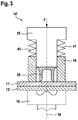
- FIG. 3 is shown schematically and simplified a punch rivet without vibrator. Compared to those in the FIGS. 2a to 2d shown punching riveting the coupling of the blank holder 16 is shown on the punch 15 here.
- the punch 15 has a radial projection on the upper end shown here.
- a spring unit 41 for example.
- the punch riveting device 10 ' has a frame 60, which is preferably in the form of a C-frame or C-bracket, on which the individual components are usually arranged in a punch riveting in order to take the desired position to each other.
- the punch rivet 10 ' for example.
- arm 3 attached. It is understood that even in the in the FIGS. 2a to 2d and 3 Punch riveting shown in the rule, such a frame may be present.
- a drive 50 which may, for example, be a spindle drive or the like, which is suitable for applying a force F for pressing in the rivet 20 into the components 11, 12.
- a holding device 35 for example.
- a vibration system 39 On the holding device 35 is a vibration generator 30, for example.
- the oscillating system 39 is arranged or fastened to the holding device 35 approximately in the center of the booster 31, which has an upper, a wider and a lower, narrower part.
- the punch 15 may, for example, be part of the sonotrode 32, i. that both components can form a structural unit.
- the booster 31 is connected to the holder 35, the booster 31 in the region where it is connected to the holder 35 has no (i.e., vibration nodes) or only a small amplitude of vibration.
- a hold-down 16 ' is shown, which is coupled by means of a spring unit 41, for example. In the form of a cylindrical helical compression spring, to the holding device 35.
- An oscillation of the oscillating system 39 is not transmitted by this type of coupling or at least only slightly to the hold-down 16 '.
- a diagram is shown on the right side of the figure, in which a curve of a vibration amplitude A of an oscillation forming in the vibration system 39 is shown above the position ⁇ .
- the region at which the oscillating system 39 is coupled to the holding device 35 is a point of low oscillation amplitude.
- the oscillation amplitude is generally lower than in the lower region of the plunger 15. In this respect, a possibly still transferable oscillation hardly affects the downholder, since the oscillation amplitude would be very small.
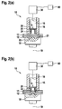
- FIG. 4b a punch rivet 10 'according to the invention is shown in a further preferred embodiment. Opposite the in FIG. 4a shown punch riveting 10 'is the hold-down 16 'is not coupled to the holding device 35, but to the oscillating system 39 in the region of the punch 15 or the sonotrode 32.
- Such a suitable region with little or no oscillation amplitude can be determined, for example, on the basis of the design of the oscillation system 39 or by means of tests.
Landscapes
- Engineering & Computer Science (AREA)
- Mechanical Engineering (AREA)
- Automatic Assembly (AREA)
- Apparatuses For Generation Of Mechanical Vibrations (AREA)
Abstract
Die Erfindung betrifft eine Stanznietvorrichtung (10') zum Verbinden wenigstens zweier Bauteile (11, 12), mit einem Stempel (15), einem Gegenhalter (18), einem Niederhalter (16') und einem Schwingungserzeuger (30), wobei der Stempel (15), der Niederhalter und der Gegenhalter (18) derart zueinander angeordnet sind, dass die wenigstens zwei Bauteile (11, 12) zwischen dem Stempel (15) und dem Gegenhalter (18) und zugleich zwischen dem Niederhalter (16') und dem Gegenhalter (18) anordenbar sind, wobei der Stempel (15) und der Schwingungserzeugers (30) miteinander gekoppelt sind und ein Schwingsystem (39) bilden, ein Antrieb (50) vorgesehen ist, an den der Stempel (15) und der Niederhalter (16') derart gekoppelt sind, dass mittels des Antriebs (50) eine Kraft (F) auf den Stempel (15) und auf den Niederhalter (16') in Richtung der Bauteile (11, 12) ausübbar ist, wobei der Niederhalter (16') derart mit dem Schwingsystem (39) gekoppelt ist, eine Schwingungsamplitude (A) des Niederhalters (16') im Kontaktbereich mit einem der Bauteile höchstes 25%, insbesondere höchstens 10%, einer Schwingungsamplitude (A) des Stempels (15) im Kontaktbereich mit einem Niet (20) aufweist, sowie ein Fertigungseinrichtung mit einer Stanznietvorrichtung (10').The invention relates to a punch rivet device (10 ') for connecting at least two components (11, 12), with a punch (15), a counter-holder (18), a hold-down (16') and a vibration generator (30), wherein the punch ( 15), the hold-down device and the counter-holder (18) are arranged relative to one another such that the at least two components (11, 12) between the punch (15) and the counter-holder (18) and at the same time between the hold-down (16 ') and the counter-holder (18) can be arranged, wherein the punch (15) and the vibration generator (30) are coupled together and form a vibration system (39), a drive (50) is provided, to which the punch (15) and the hold-down (16 '; ) are coupled in such a way that by means of the drive (50) a force (F) can be exerted on the punch (15) and on the hold-down device (16 ') in the direction of the components (11, 12), wherein the hold-down device (16') is coupled to the oscillating system (39), a vibration amplitude (A) of the blank holder (16 ' ) in the contact region with one of the components most 25%, in particular at most 10%, a vibration amplitude (A) of the punch (15) in the contact region with a rivet (20), and a manufacturing device with a punch riveting (10 ').
Description
Die vorliegende Erfindung betrifft eine Stanznietvorrichtung zum Verbinden wenigstens zweier Bauteile sowie eine Fertigungsvorrichtung mit einer solchen Stanznietvorrichtung.The present invention relates to a punch riveting apparatus for connecting at least two components and to a production apparatus having such a punch riveting apparatus.
Verfahren und Vorrichtungen zum Stanznieten dienen zum Verbinden mindestens zweier in einem Verbindungsbereich insbesondere eben ausgebildeter Bauteile (Fügepartner). Ein Stanznietverfahren zeichnet sich dadurch aus, dass ein Vorlochen der miteinander zu verbindenden Bauteile nicht erforderlich ist. Vielmehr wird ein Niet mittels eines Stempels oder eines Stempelwerkzeugs in die wenigstens zwei Bauteile eingedrückt, wobei durch einen entsprechend geformten Gegenhalter, bspw. in Form einer Matrize, der mit dem Stempelwerkzeug zusammenwirkt, sichergestellt ist, dass der Niet sich in einer bestimmten Art und Weise innerhalb der miteinander zu verbindenden Bauteile verformt, um eine kraft- und formschlüssige Verbindung zwischen den Bauteilen herzustellen und gleichzeitig ein Durchdringen des dem Niet abgewandten Bauteils zu vermeiden.Methods and devices for punch riveting serve for connecting at least two in a connection region in particular flat trained components (joint partners). A punch riveting method is characterized in that a pre-punching of the components to be joined together is not required. Rather, a rivet is pressed by means of a punch or a punch tool in the at least two components, being ensured by a correspondingly shaped counter-holder, for example. In the form of a die, which cooperates with the punch tool, that the rivet in a certain way deformed within the components to be joined together to produce a positive and positive connection between the components while avoiding penetration of the component facing away from the rivet.
Weiterhin sind bspw. aus der
Erfindungsgemäß werden eine Stanznietvorrichtung und eine Fertigungseinrichtung mit den Merkmalen der unabhängigen Patentansprüche vorgeschlagen. Vorteilhafte Ausgestaltungen sind Gegenstand der Unteransprüche sowie der nachfolgenden Beschreibung.According to the invention, a punch riveting device and a production device with the features of the independent patent claims are proposed. Advantageous embodiments are the subject of the dependent claims and the following description.
Eine erfindungsgemäße Stanznietvorrichtung dient zum Verbinden wenigstens zweier Bauteile und weist einen Stempel, einen Gegenhalter, einen Niederhalter und einen Schwingungserzeuger auf. Dabei sind der Stempel, der Niederhalter und der Gegenhalter derart zueinander angeordnet, dass die wenigstens zwei Bauteile zwischen dem Stempel und dem Gegenhalter und zugleich zwischen dem Niederhalter und dem Gegenhalter anordenbar sind. Der Stempel und der Schwingungserzeugers sind miteinander gekoppelt und bilden ein Schwingsystem und es ist ein Antrieb vorgesehen, an den der Stempel und der Niederhalter derart gekoppelt sind, dass mittels des Antriebs eine Kraft auf den Stempel und auf den Niederhalter in Richtung der Bauteile ausübbar ist. Dabei ist der Niederhalter derart mit dem Schwingsystem gekoppelt, dass eine Schwingungsamplitude des Niederhalters im Kontaktbereich mit einem der Bauteile höchstens 25%, insbesondere höchstens 10%, einer Schwingungsamplitude des Stempels im Kontaktbereich mit einem Niet aufweist. Mit anderen Worten ist der Niederhalter somit derart mit dem Schwingsystem gekoppelt, dass vom Schwingsystem auf den Niederhalter nur eine möglichst geringe, vorzugsweise gar keine, Schwingung übertragbar ist. Bevorzugt beträgt die Schwingungsamplitude des Niederhalters im Kontaktbereich mit einem der Bauteile 0% (d.h. Schwingungsknoten) der Schwingungsamplitude des Stempels im Kontaktbereich mit dem Niet bzw. es ist vom Schwingsystem auf den Niederhalter keine Schwingung übertragbar. Als Niet kann hierbei sowohl ein sog. Halbhohlniet als auch ein sog. Vollniet verwendet werden.A punch riveting device according to the invention serves for connecting at least two components and has a punch, a counter-holder, a holding-down device and a vibration generator. In this case, the punch, the hold-down and the counter-holder are arranged to each other such that the at least two components between the punch and the counter-holder and at the same time between the hold-down and the counter-holder can be arranged. The punch and the oscillator are coupled together and form a vibration system and there is provided a drive to which the punch and the hold-down are coupled so that by means of the drive, a force on the punch and on the hold-down in the direction of the components is exercisable. In this case, the holding-down device is coupled to the oscillating system in such a way that an oscillation amplitude of the holding-down device in the area of contact with one of the components is at most 25%, in particular at most 10%, of a vibration amplitude of the stamp in the contact area with a rivet. In other words, the holding-down device is thus coupled to the oscillating system in such a way that only a minimum, preferably no, oscillation can be transmitted from the oscillating system to the holding-down device. Preferably, the vibration amplitude of the blank holder in the contact area with one of the components is 0% (i.e., node) of the vibration amplitude of the punch in the contact area with the rivet, and no vibration is transmittable from the vibrating system to the blank holder. As a rivet, both a so-called semi-tubular rivet and a so-called solid rivet can be used.
Bei herkömmlichen Stanznietvorrichtungen ohne Schwingungserzeuger kann auf einfache Weise ein Antrieb vorgesehen sein, der zugleich eine Kraft auf den Stempel zum Eindrücken eines Niets in die Bauteile und eine Kraft auf den Niederhalter zum Andrücken der Bauteile an den Gegenhalter ausüben kann. Bei einer Stanznietvorrichtung mit Schwingungserzeuger, bei der während des Eindrückens des Niets der Stempel in Schwingung versetzt wird, kann hierbei auch der Niederhalter in Schwingung versetzt werden, wodurch die gewünschte Andrückkraft durch den Niederhalter auf die Bauteile gemindert wird. Dies kann zu schlechten Nietergebnissen führen bzw. den Effekt der Schwingungseinkopplung mindern oder gar vollständig behindern. Während zur Lösung dieses Problems für den Stempel und den Niederhalter zwar separate Antriebe vorgesehen sein können, kommt eine erfindungsgemäße Stanznietvorrichtung mit nur einem Antrieb aus. Dies ist möglich, da der Niederhalter auf geeignete Weise mit dem von Schwingungserzeuger und Stempel gebildeten Schwingsystem gekoppelt ist, wodurch zwar der Stempel wie gewünscht in Schwingung versetzt wird, der Niederhalter jedoch nicht. Auf diese Weise kann eine Stanznietvorrichtung mit nur einem Antrieb zur Verfügung gestellt werden, welche daher einfach und kostengünstig ist.In conventional punch riveting without vibration generator can be provided in a simple manner, a drive which can exert a force on the punch for pressing a rivet into the components and a force on the hold-down for pressing the components to the anvil at the same time. In a punch riveter with vibrator, in which during the depression of the rivet of the stamp in Oscillation is offset, in this case also the hold-down can be set in vibration, whereby the desired pressing force is reduced by the hold-down on the components. This can lead to poor rivet results or reduce the effect of vibration coupling or even completely hinder. While separate drives can be provided for the solution of this problem for the punch and the hold-down, a punch riveting device according to the invention with only one drive is required. This is possible because the hold-down is suitably coupled to the vibrating system formed by the vibrator and the punch, which causes the punch to vibrate as desired, but not the hold-down. In this way, a punch riveting device can be provided with only one drive, which is therefore simple and inexpensive.
Vorzugsweise ist der Niederhalter in einem Bereich des Schwingungssystems, in welchem eine Schwingungsamplitude des Schwingsystem höchstens 10%, insbesondere höchstens 5%, der Schwingungsamplitude des Stempels im Kontaktbereich mit dem Niet aufweist, an das Schwingsystem gekoppelt. Mit anderen Worten ist der Niederhalter in einem Bereich des Schwingungssystems, in welchem eine Schwingung des Schwingsystems eine möglichst geringe Amplitude aufweist, an das Schwingsystem gekoppelt. Bevorzugt beträgt die Schwingungsamplitude des Schwingsystems in diesem Bereich 0% (d.h. Schwingungsknoten) der Schwingungsamplitude des Stempels im Kontaktbereich mit dem Niet. Ein solches Schwingsystem weist in der Regel weiterhin einen Booster und/oder eine Sonotrode, insbesondere auch nur eine Sonotrode, auf, über welche der Stempel mit dem Schwingungserzeuger gekoppelt ist. Insbesondere kann der Stempel dabei auch als ein Teil der Sonotrode ausgebildet sein. Eine Schwingung wird dabei von dem Schwingungserzeuger erzeugt und über den Booster wird die Amplitude der Schwingung übersetzt. In Anhängigkeit von der geometrischen Auslegung kann die Amplitude untersetzt, gleichbleibend weitergeleitet, aber in der Regel übersetzt und demzufolge vergrößert werden. Wie auch der Booster bildet die Sonotrode einen Resonanzkörper, bei dem die Amplitude in der Regel weiter vergrößert wird. Insgesamt bildet sich dabei eine stehende longitudinale Schwingung im Schwingsystem aus. Diese stehende Schwingung weist somit auch Stellen oder Bereiche auf, in denen die Amplitude Null oder zumindest nahezu Null ist. Wird nun der Niederhalter in einem solchen Bereich des Schwingsystems an das Schwingsystem gekoppelt, wird keine oder nahezu keine Schwingung auf den Niederhalter übertragen. Somit kann eine gleichmäßige Kraft auf die Bauteile ausgeübt werden. Es versteht sich, dass die entsprechenden Bereiche von der Ausgestaltung des Schwingsystems abhängen.Preferably, the hold-down is in a region of the vibration system in which a vibration amplitude of the vibration system at most 10%, in particular at most 5%, the vibration amplitude of the punch in the contact region with the rivet, coupled to the vibrating system. In other words, the hold-down device is coupled to the vibration system in a region of the vibration system in which an oscillation of the vibration system has the lowest possible amplitude. The oscillation amplitude of the oscillating system in this area is preferably 0% (ie vibration node) of the oscillation amplitude of the stamp in the area of contact with the rivet. As a rule, such a vibration system furthermore has a booster and / or a sonotrode, in particular also only a sonotrode, via which the ram is coupled to the vibration generator. In particular, the stamp can also be designed as a part of the sonotrode. A vibration is generated by the vibration generator and via the booster, the amplitude of the vibration is translated. Depending on the geometric design, the amplitude can be reduced, constantly transmitted, but usually translated and thus increased. Like the booster, the sonotrode forms a resonator, where the amplitude is usually further increased. Overall, this forms a standing longitudinal vibration in the vibrating system. This standing oscillation thus also has points or areas in which the amplitude is zero or at least almost zero. Now, if the hold-down is coupled in such an area of the vibration system to the vibration system, no or almost no vibration is transmitted to the hold-down. Thus, a uniform force can be exerted on the components. It It is understood that the corresponding areas depend on the design of the vibration system.
Vorteilhafterweise ist eine Haltevorrichtung vorgesehen, die an dem Antrieb befestigt ist, und an welcher das Schwingsystem befestigt ist. Insbesondere umgibt die Haltevorrichtung den Schwingungserzeuger wenigstens teilweise. Durch eine solche Haltevorrichtung ist eine besonders einfache und platzsparende Anordnung des Schwingsystems in der Stanznietvorrichtung möglich. Insbesondere kann auf diese Weise auch das Schwingsystem weitgehend von dem Antrieb bezüglich Schwingungsübertragungen abgekoppelt werden.Advantageously, a holding device is provided, which is fastened to the drive, and to which the oscillating system is attached. In particular, the holding device surrounds the vibrator at least partially. By such a holding device is a particularly simple and space-saving arrangement of the vibration system in the punch riveting possible. In particular, in this way, the oscillating system can be largely decoupled from the drive with respect to vibration transmissions.
Es ist von Vorteil, wenn der Niederhalter an der Haltevorrichtung getrennt von dem Schwingsystem befestigt ist. Somit sind sowohl das Schwingsystem und der Niederhalter an der Haltevorrichtung und über die Haltevorrichtung an dem Antrieb befestigt. Damit ist eine Kraftübertragung vom Antrieb auf den Stempel und den Niederhalter möglich. Allerdings ist durch die getrennte Befestigung von Schwingsystem und Niederhalter an der Haltevorrichtung kein unmittelbarer Kontakt zwischen Schwingsystem und Niederhalter gegeben, sondern es besteht lediglich ein mittelbarer Kontakt über die Haltevorrichtung, welcher zudem bei geeigneter Ausgestaltung der Haltevorrichtung gering gehalten werden kann. Auf diese Weise wird eine Schwingungsübertragung vom Schwingsystem auf den Niederhalter weitgehend vermieden. Wird das Schwingsystem zudem in einem Bereich des Schwingsystems, in welchem eine Schwingung des Schwingsystems eine möglichst geringe, insbesondere keine, Amplitude aufweist, an der Haltevorrichtung befestigt, wird eine Schwingungsübertragung auf den Niederhalter weiter reduziert. Alternativ oder zusätzlich kann darauf geachtet werden, dass das Schwingsystem nahe dem Schwingungserzeuger bzw. fern von dem Stempel an der Haltevorrichtung befestigt wird, da hier eine Amplitude in der Regel deutlich geringer als im Bereich des Stempels ist.It is advantageous if the holding-down device is fastened to the holding device separately from the oscillating system. Thus, both the oscillating system and the hold-down to the holding device and the holding device are attached to the drive. Thus, a power transmission from the drive to the punch and the hold-down is possible. However, no direct contact between the oscillating system and hold-down is given by the separate attachment of the oscillating system and hold-down on the fixture, but there is only an indirect contact on the holding device, which can also be kept low with a suitable design of the holding device. In this way, a vibration transmission from the vibration system to the holddown is largely avoided. If the oscillating system is also fastened to the holding device in a region of the oscillating system in which a vibration of the oscillating system has the lowest possible, in particular no, amplitude, a vibration transmission to the holding-down device is further reduced. Alternatively or additionally, care must be taken that the vibration system is fastened near the vibration generator or remote from the punch on the holding device, since an amplitude is generally significantly lower than in the area of the punch.
Alternativ ist bevorzugt, dass der Niederhalter in einem Bereich des Stempels, in welchem eine Schwingungsamplitude des Schwingsystems höchstens 10%, insbesondere höchstens 5%, der Schwingungsamplitude des Stempels im Kontaktbereich des Niets aufweist, an das Schwingsystem gekoppelt ist. Mit anderen Worten ist der Niederhalter in einem Bereich des Stempels, in welchem eine Schwingung des Schwingsystems eine möglichst geringe Amplitude aufweist, an das Schwingsystem gekoppelt. Bevorzugt beträgt die Schwingungsamplitude des Schwingsystems in diesem Bereich 0% (d.h. Schwingungsknoten) der Schwingungsamplitude des Stempels im Kontaktbereich mit dem Niet. Dies ist möglich, da in der Regel auch im Stempel ein Bereich auftritt, in dem die bereits erwähnte stehende Schwingung keine oder zumindest nahezu keine Amplitude aufweist. Wird der Niederhalter hier angekoppelt, kann der Niederhalter sehr kompakt ausgeführt werden, da der Stempel nahe an den Bauteilen liegt.Alternatively, it is preferred that the hold-down device is coupled to the oscillating system in a region of the stamp in which a vibration amplitude of the oscillating system has at most 10%, in particular at most 5%, of the oscillation amplitude of the stamp in the contact region of the rivet. In other words, the holding-down device is coupled to the oscillating system in a region of the stamp in which an oscillation of the oscillating system has the lowest possible amplitude. Preferably, the oscillation amplitude of the oscillating system in this range is 0% (ie Vibration node) of the vibration amplitude of the punch in the contact area with the rivet. This is possible since, as a rule, a region also occurs in the stamp in which the already mentioned stationary oscillation has no or at least almost no amplitude. If the hold-down is coupled here, the hold-down can be made very compact, since the punch is close to the components.
Vorzugsweise weist der Niederhalter eine Federeinheit auf, über welche er mit dem Schwingsystem gekoppelt ist. Auf diese Weise kann der Relativbewegung zwischen Stempel und Niederhalter aufgrund des Absenkens des Stempels beim Eindrücken des Niets Rechnung getragen werden, während gleichzeitig die Kraft vom Antrieb auf den Niederhalter wirkt. Im Falle einer geeigneten Ankopplung des Niederhalters an die Haltevorrichtung oder an den Stempel, kann die Federeinheit dabei bspw. eine zylindrische Schraubendruckfeder oder Tellerfedern oder eine Elastomerfeder aufweisen. Es kann auch eine schwingungs- bzw. schalldämmende Beschichtung wie bspw. ein geeigneter Lack am Niederhalter vorgesehen sein, insbesondere in einem Bereich, an dem der Niederhalter an das Schwingsystem oder andere Komponenten angekoppelt ist. Damit können Schwingungen des Niederhalters reduziert werden. Über eine Federsteifigkeit bzw. eine Federkonstante kann eine Niederhaltekraft währen des Eindrückens des Niets angepasst werden. Unter Berücksichtigung der vom Antrieb aufgebrachten Kraft kann die Federkonstante geeignet gewählt werden, so dass bspw. Niederhaltekräfte zwischen 2 kN und 8 kN erhalten werden. Insbesondere kann beim Verlauf der Niederhaltekraft während des Eindrückens auch berücksichtigt werden, dass die Federkonstante bspw. linear bei einer zylindrischen Schraubendruckfeder, degressiv bei Tellerfedern oder progressiv bei druckbelasteten Elastomerfedern verläuft.Preferably, the hold-down on a spring unit, via which it is coupled to the oscillating system. In this way, the relative movement between the punch and hold-down due to the lowering of the punch when pressing the rivet can be taken into account, while the force from the drive acts on the hold-down. In the case of a suitable coupling of the hold-down device to the holding device or to the stamp, the spring unit can have, for example, a cylindrical helical compression spring or disk springs or an elastomeric spring. It is also possible to provide a vibration-damping or sound-insulating coating, for example a suitable lacquer, on the hold-down device, in particular in a region where the hold-down device is coupled to the oscillating system or other components. This vibration of the blank can be reduced. By means of a spring stiffness or a spring constant, a hold-down force can be adapted during the indentation of the rivet. Taking into account the force applied by the drive, the spring constant can be suitably selected so that, for example, hold-down forces between 2 kN and 8 kN are obtained. In particular, during the course of the hold-down force during the indentation, it can also be taken into account that the spring constant runs, for example, linearly with a cylindrical helical compression spring, degressive with disc springs or progressively with pressure-loaded elastomer springs.
Vorteilhafterweise weist die Federeinheit ein Dämpfungsmaterial auf, das dazu geeignet ist, eine Amplitude der vom Schwingungserzeuger erzeugten Schwingungen wenigstens auf die Hälfte zu reduzieren. Insbesondere kann es sich bei der Federeinheit bspw. um eine Elastomerfeder handeln, d.h. ein elastisches Material, das zwar die lineare Bewegung des Antriebs überträgt, nicht jedoch die in der Regel hochfrequente, vom Schwingungserzeuger erzeugte Schwingung. Anstatt einer Elastomerfeder kann auch nur zusätzlich zu einer konventionellen Feder ein Dämpfungsmaterial, bspw. ein Elastomer, verwendet werden.Advantageously, the spring unit has a damping material which is suitable for reducing an amplitude of the vibrations generated by the vibration generator to at least half. In particular, the spring unit may, for example, be an elastomeric spring, ie an elastic material which transmits the linear movement of the drive, but not the generally high-frequency oscillation generated by the oscillator. Instead of an elastomeric spring, only in addition to a conventional spring, a damping material, for example. An elastomer can be used.
Es ist von Vorteil, wenn der Schwingungserzeuger als Schall-Generator, insbesondere als Ultraschall-Generator, weiter insbesondere eine Piezokonverter, ausgebildet ist. Hierbei handelt es sich um eine einfache Methode zur Schwingungserzeugung.It is advantageous if the vibration generator is designed as a sound generator, in particular as an ultrasonic generator, more particularly a piezo converter. This is a simple method for vibration generation.
Zweckmäßigerweise weist das Schwingsystem weiterhin einen Booster und/oder eine Sonotrode auf, über welche der Stempel mit dem Schwingungserzeuger gekoppelt ist. Insbesondere ist der Stempel als ein Teil der Sonotrode ausgebildet. Hierbei handelt es sich um eine übliche und einfach zu verwendete Anordnung für ein Schwingsystem für eine Stanznietvorrichtung.Conveniently, the vibration system further comprises a booster and / or a sonotrode, via which the punch is coupled to the vibration generator. In particular, the stamp is formed as a part of the sonotrode. This is a common and easy to use arrangement for a vibration system for a punch riveter.
Zweckmäßigerweise weist die Stanznietvorrichtung weiterhin einen Rahmen auf, der eine Schnittstelle für eine Anbringung der Stanznietvorrichtung an einer Fertigungseinrichtung, wie bspw. einem Industrieroboter, aufweist. Dies ermöglicht eine sehr einfache Montage bspw. im Rahmen eines Austauschs.Conveniently, the punch riveting apparatus further comprises a frame having an interface for attachment of the punch riveting apparatus to a manufacturing apparatus such as an industrial robot. This allows a very simple assembly, for example. In the context of an exchange.
Eine erfindungsgemäße Fertigungseinrichtung weist eine erfindungsgemäße Stanznietvorrichtung auf.A production device according to the invention has a punch riveting device according to the invention.
Zur Vermeidung von Wiederholungen sei bezüglich weiterer Vorteile einer erfindungsgemäßen Fertigungsvorrichtung auf die obigen Ausführungen zur erfindungsgemäßen Stanznietvorrichtung verwiesen.To avoid repetition, reference is made to the above statements on the punch riveting apparatus according to the invention with regard to further advantages of a production apparatus according to the invention.
Weitere Vorteile und Ausgestaltungen der Erfindung ergeben sich aus der Beschreibung und der beiliegenden Zeichnung.Further advantages and embodiments of the invention will become apparent from the description and the accompanying drawings.
Es versteht sich, dass die vorstehend genannten und die nachfolgend noch zu erläuternden Merkmale nicht nur in der jeweils angegebenen Kombination, sondern auch in anderen Kombinationen oder in Alleinstellung verwendbar sind, ohne den Rahmen der vorliegenden Erfindung zu verlassen.It is understood that the features mentioned above and those yet to be explained below can be used not only in the particular combination indicated, but also in other combinations or in isolation, without departing from the scope of the present invention.
Die Erfindung ist anhand von Ausführungsbeispielen in der Zeichnung schematisch dargestellt und wird im Folgenden unter Bezugnahme auf die Zeichnung ausführlich beschrieben.The invention is illustrated schematically by means of exemplary embodiments in the drawing and will be described in detail below with reference to the drawing.
- Figur 1FIG. 1
- zeigt vereinfacht und schematisch eine erfindungsgemäße Fertigungseinrichtung in einer bevorzugten Ausführungsform.shows simplified and schematically a manufacturing device according to the invention in a preferred embodiment.
- Figuren 2a bis 2dFIGS. 2a to 2d
- zeigen eine Stanznietvorrichtung bei verschiedenen Phasen der Durchführung eines Stanznietverfahrens.show a punch riveting apparatus at various stages of performing a punch riveting process.
- Figur 3FIG. 3
- zeigt schematisch eine Stanznietvorrichtung ohne Schwingungserzeuger.schematically shows a punch riveting without vibration generator.
- Figuren 4a und 4bFIGS. 4a and 4b
- zeigen schematisch erfindungsgemäße Stanznietvorrichtungen in verschiedenen bevorzugten Ausführungsformen.show schematically punch riveting according to the invention in various preferred embodiments.
In
Die Fertigungseinrichtung 100 weist dabei eine auf einem Boden angeordnete Trägerstruktur 3 und zwei daran angeordnete, miteinander verbundene und bewegliche Arme 4 und 5 auf. Am Ende des Armes 5 ist eine erfindungsgemäße Stanznietvorrichtung 10' angeordnet, welche in den
Weiterhin ist eine Recheneinheit 80 gezeigt, bei der es sich bspw. um eine Steuereinheit für die Stanznietvorrichtung 10' handelt. Die Recheneinheit 80 kann zudem auch als Steuereinheit für die gesamte Fertigungseinrichtung, d.h. neben der Stanznietvorrichtung insbesondere auch für die Ansteuerung der beweglichen Arme vorgesehen sein. Weiterhin sind Anzeigemittel 90, bspw. ein Display, vorgesehen, auf denen bspw. aktuelle Betriebsparameter der Stanznietvorrichtung angezeigt werden können.Furthermore, a
In den
Der Stempel 15 ist von einem hülsenförmigen Niederhalter 16 radial umgeben und relativ zu diesem in Längsrichtung beweglich angeordnet. Insbesondere ist der Stempel 15 mit einem hier nicht dargestellten Antrieb, bspw. einem hydraulischen oder pneumatischen Antrieb, gekoppelt, der dazu dient, eine zum Eindrücken eines Niets 20 in die beiden Bauteile 11, 12 benötigte Kraft F aufzubringen.The
Ebenfalls ist der Niederhalter 16 dazu eingerichtet, gegen die Oberfläche des dem Stempel 15 zugewandten Bauteils 11 mit einer Niederhaltekraft zu drücken. Hierzu kann bspw. ein eigener Antrieb vorgesehen sein. Jedoch kann der Niederhalter auch an den Antrieb des Stempels 15 gekoppelt sein, bspw. mittels einer Feder.Also, the hold-down 16 is adapted to press against the surface of the die 15 facing
Auf der dem Stempel 15 und dem Niederhalter 16 gegenüberliegenden Seite der beiden Bauteile 11, 12 ist eine als Gegenhalter wirkende Matrize 18 angeordnet. Die Matrize 18 ist ebenfalls in Richtung einer Längsachse 19, in deren Richtung auch der Stempel 15 und der Niederhalter 16 beweglich angeordnet sind, heb- und senkbar. Der Niederhalter 16 und die Matrize 18 dienen dazu, die beiden Bauteile 11, 12 zwischen dem Niederhalter 16 und der Matrize 18 während der Bearbeitung durch den Stempel 15 einzuspannen bzw. zusammenzudrücken. Die Matrize 18 weist auf der dem Bauteil 12 zugewandten Seite eine ebene Oberseite 21 auf, von der eine mulden- bzw. kuhlenförmige Ausnehmung 22, ausgeht. Die Matrizenausnehmung kann dabei flach, kegel- oder kugelförmig sein oder einen Dom oder. Dorn in der Mitte der Ausnehmung besitzen.On the
Der Niet 20, hier beispielhaft ein Halbhohlniet, besteht bevorzugt aus einem gegenüber den Werkstoffen der beiden Bauteile 11, 12 härteren Material, zumindest im Bereich des Nietschafts 24. Die dem Bauteil 11 abgewandte, ebene Oberseite 26 ist in Wirkverbindung mit dem Stempel 15 angeordnet, der an der Oberseite 26 des Niets 20 flächig anliegt. Somit stellt die die Oberseite 26 des Niets eine Kontaktstelle 27 zwischen dem Niet und dem Stempel dar.The
Der Stempel 15 ist mit einem Schwingungserzeuger 30 zur Erzeugung von Schwingungen bzw. Vibrationen wirkverbunden. Insbesondere werden mittels des Schwingungserzeugers 30 Ultraschallschwingungen mit einer Schwingweite (Abstand zwischen maximaler positiver und negativer Amplitude einer Schwingung) zwischen 10 µm und 110 µm (entspricht einer Amplitude von 5 µm bis 55 µm) und einer Frequenz zwischen 15 kHz und 35 kHz oder ggf. auch höher erzeugt.The
Diese Schwingungen 15 werden von dem Schwingungserzeuger 30 über den Stempel 15 in den Niet 20 eingekoppelt. Die Einkopplungsrichtung der Vibrationen des Schwingungserzeugers 30 kann dabei bspw. parallel zur Längsachse 19, das heißt parallel zur Fügerichtung des Niets 20 in die Bauteile 11, 12 erfolgen. Der Schwingungserzeuger 30 ist an die Recheneinheit 80 angebunden, und kann von dieser angesteuert werden.These
Die in
In einer in
Während des weiteren Bewegungswegs bzw. der weiteren Abwärtsbewegung des Niets 20 entsprechend der
Wesentlich dabei ist, dass entsprechend der
Nachdem der Niet 20 die in der
In
Der Stempel 15 weist dabei an dem hier gezeigten oberen Ende einen radialen Vorsprung auf. An diesem radialen Vorsprung ist eine Federeinheit 41, bspw. in Form einer zylindrischen Schraubendruckfeder, angebracht, über welche der Niederhalter 16 an den Stempel 15 gekoppelt ist.The
Wird nun über einen geeigneten Antrieb eine Kraft F auf den Stempel 15 zum Eindrücken des Niets 20 ausgeübt, so wird die Kraft gleichzeitig auch auf den Niederhalter 16 ausgeübt, mittels welchem die Bauteile 11, 12 an den Gegenhalter bzw. die Matrize 18 gedrückt werden, wobei durch die Federeinheit 41 der Relativbewegung zwischen Stempel 15 und Niederhalter 16 Rechnung getragen wird.If a force F is now exerted on the
An der gezeigten Anordnung von Stempel und Niederhalter ist zu erkennen, dass diese Anordnung für eine Stanznietvorrichtung mit Schwingungserzeuger ungeeignet ist, da die Schwingungen nicht nur auf den Stempel, sondern auch auf den Niederhalter übertragen würden. Die Bauteile 11, 12 würden mit einem schwingenden Niederhalter nicht zufriedenstellend an den Gegenhalter 18 gedrückt.It can be seen from the illustrated arrangement of punch and downholder that this arrangement is unsuitable for a punch riveter with a vibrator, since the oscillations would be transmitted not only to the punch but also to the downholder. The
In
Weiterhin ist ein Antrieb 50 gezeigt, bei dem es sich bspw. um einen Spindelantrieb oder dergleichen handeln kann, der dazu geeignet ist, eine Kraft F zum Eindrücken des Niets 20 in die Bauteile 11, 12 aufzubringen. An dem Antrieb 50 ist eine Haltevorrichtung 35, bspw. in Form eines Rahmens oder eines Gestells, angebracht. An der Haltevorrichtung 35 ist ein Schwingsystem 39, das vorliegend einen Schwingungserzeuger 30, bspw. einen Ultraschall-Generator, einen Booster 31, eine Sonotrode 32 sowie einen Stempel 15 aufweist, angeordnet.Furthermore, a
Wie der Figur zu entnehmen ist, ist das Schwingsystem 39 in etwa in der Mitte des Boosters 31, der einen oberen, breiteren und einen unteren, schmäleren Teil aufweist, an der Haltevorrichtung 35 angeordnet bzw. befestigt. Hierbei sei angemerkt, dass der Stempel 15 bspw. Teil der Sonotrode 32 sein kann, d.h. dass beide Komponenten eine bauliche Einheit bilden können. Der Booster 31 ist zwar mit der Haltevorrichtung 35 verbunden, jedoch weist der Booster 31 in dem Bereich, an dem er mit der Haltevorrichtung 35 verbunden ist, keine (d.h. Schwingungsknoten) oder nur eine kleine Schwingungsamplitude auf.As can be seen from the figure, the oscillating
Weiterhin ist ein Niederhalter 16' gezeigt, der mittels einer Federeinheit 41, bspw. in Form einer zylindrischen Schraubendruckfeder, an die Haltevorrichtung 35 gekoppelt ist. Der Niederhalter 16' ist somit getrennt von dem Schwingsystem 39 an die Haltevorrichtung 35 gekoppelt, d.h. der Niederhalter 16' ist nur mittelbar mit dem Schwingsystem 39 gekoppelt. Eine Schwingung des Schwingsystems 39 wird durch diese Art der Kopplung gar nicht oder zumindest nur unwesentlich auf den Niederhalter 16' übertragen.Furthermore, a hold-down 16 'is shown, which is coupled by means of a
Weiterhin ist auf der rechten Seite der Figur ein Diagramm gezeigt, in dem ein Verlauf einer Schwingungsamplitude A einer sich in dem Schwingsystem 39 ausbildenden Schwingung über der Position λ gezeigt. Dabei ist zu sehen, dass der Bereich, an der das Schwingsystem 39 an die Haltevorrichtung 35 gekoppelt ist, eine Stelle geringer Schwingungsamplitude ist. Zudem ist in diesem, hier dem oberen, Bereich des Schwingsystems 39 die Schwingungsamplitude generell geringer als im unteren Bereich des Stempels 15. Insofern wirkt sich eine möglicherweise dennoch übertragbare Schwingung kaum auf den Niederhalter aus, da die Schwingungsamplitude sehr gering wäre.Furthermore, a diagram is shown on the right side of the figure, in which a curve of a vibration amplitude A of an oscillation forming in the
In
An dem Diagramm an der rechten Seite in der Figur, in welchem wiederum ein Verlauf einer Schwingungsamplitude A einer sich in dem Schwingsystem 39 ausbildenden Schwingung über der Position λ gezeigt ist, ist zu erkennen, dass der Niederhalter 16' mittels der Federeinheit 41 in einem Bereich, hier am oberen Ende des Stempels 15, des Schwingsystems 39 angekoppelt ist, in dem die Schwingungsamplitude sehr gering, möglichst Null, ist. Vorliegend ist die Federeinheit 41 dazu an einer Komponente 42 angebracht, welche wiederum in dem betreffenden Bereich des Stempels 15 angebracht ist.It can be seen from the diagram on the right-hand side in the figure, in which a course of a vibration amplitude A of a vibration forming in the
Ein solcher geeigneter Bereich mit geringer bzw. keiner Schwingungsamplitude kann dabei bspw. anhand der Auslegung des Schwingsystems 39 oder mittels Tests ermittelt werden. Durch eine solche Kopplung des Niederhalters 16' an das Schwingsystem 39 kann erreicht werden, dass keine oder zumindest nahezu keine Schwingungen vom Schwingsystem 39 an den Niederhalter 16' übertragen werden.Such a suitable region with little or no oscillation amplitude can be determined, for example, on the basis of the design of the
Claims (13)
Applications Claiming Priority (1)
| Application Number | Priority Date | Filing Date | Title |
|---|---|---|---|
| DE102015214014.8A DE102015214014A1 (en) | 2015-07-24 | 2015-07-24 | Punch riveting device and manufacturing device |
Publications (2)
| Publication Number | Publication Date |
|---|---|
| EP3120951A1 true EP3120951A1 (en) | 2017-01-25 |
| EP3120951B1 EP3120951B1 (en) | 2020-02-05 |
Family
ID=56112858
Family Applications (1)
| Application Number | Title | Priority Date | Filing Date |
|---|---|---|---|
| EP16172823.3A Active EP3120951B1 (en) | 2015-07-24 | 2016-06-03 | Self-piercing rivet device and production device |
Country Status (2)
| Country | Link |
|---|---|
| EP (1) | EP3120951B1 (en) |
| DE (1) | DE102015214014A1 (en) |
Cited By (3)
| Publication number | Priority date | Publication date | Assignee | Title |
|---|---|---|---|---|
| CN109909435A (en) * | 2017-12-12 | 2019-06-21 | 罗伯特·博世有限公司 | For placement unit, the stamping riveting device of stamping riveting device and for the method for connecting elements |
| EP3505270A1 (en) * | 2018-01-02 | 2019-07-03 | Robert Bosch GmbH | Setting unit for a punch rivet device, punch rivet device and method for manufacturing the same |
| GB2570778A (en) * | 2017-12-12 | 2019-08-07 | Bosch Gmbh Robert | Setting unit for a self-piercing rivet device, self-piercing rivet device and method for connecting component parts |
Families Citing this family (2)
| Publication number | Priority date | Publication date | Assignee | Title |
|---|---|---|---|---|
| DE102017205264A1 (en) * | 2017-03-29 | 2018-10-04 | Robert Bosch Gmbh | Punching riveting device and production device |
| DE102017210458A1 (en) * | 2017-06-22 | 2018-12-27 | Robert Bosch Gmbh | Punching device with vibration generator |
Citations (5)
| Publication number | Priority date | Publication date | Assignee | Title |
|---|---|---|---|---|
| EP1108480A2 (en) * | 1999-12-09 | 2001-06-20 | Hahn, Ortwin, Prof. Dr.-Ing. | Device and method for effecting a mechanical |
| EP0890397B1 (en) * | 1997-07-09 | 2003-03-26 | Hahn, Ortwin, Prof. Dr.-Ing. | Apparatus and method of mechanical joining from sheet metal plates, profiles or multiple-sheet metal connections |
| DE10341716A1 (en) * | 2003-03-25 | 2004-10-14 | Forschungsgesellschaft Umformtechnik Mbh | Radial forming apparatus for e.g. rod, wire-shaped workpiece, has processing tools provided around workpiece, arranged orthogonal to longitudinal axis of workpiece, and oscillated radially by ultrasonic exciting units |
| WO2010012973A1 (en) * | 2008-07-30 | 2010-02-04 | Henrob Limited | Joining apparatus and method |
| DE102014203357A1 (en) | 2014-02-25 | 2015-08-27 | Henkel Ag & Co. Kgaa | Presentation unit for a mass |
Family Cites Families (2)
| Publication number | Priority date | Publication date | Assignee | Title |
|---|---|---|---|---|
| DE19905527B4 (en) * | 1999-02-10 | 2006-11-23 | Böllhoff GmbH | Device for joining workpieces made of ductile material |
| DE102014203757B4 (en) * | 2014-02-28 | 2022-03-31 | Robert Bosch Gmbh | Method for connecting at least two components using the punch riveting method, device for carrying out the method, production facility and use of the method |
-
2015
- 2015-07-24 DE DE102015214014.8A patent/DE102015214014A1/en not_active Withdrawn
-
2016
- 2016-06-03 EP EP16172823.3A patent/EP3120951B1/en active Active
Patent Citations (6)
| Publication number | Priority date | Publication date | Assignee | Title |
|---|---|---|---|---|
| EP0890397B1 (en) * | 1997-07-09 | 2003-03-26 | Hahn, Ortwin, Prof. Dr.-Ing. | Apparatus and method of mechanical joining from sheet metal plates, profiles or multiple-sheet metal connections |
| EP1108480A2 (en) * | 1999-12-09 | 2001-06-20 | Hahn, Ortwin, Prof. Dr.-Ing. | Device and method for effecting a mechanical |
| DE10341716A1 (en) * | 2003-03-25 | 2004-10-14 | Forschungsgesellschaft Umformtechnik Mbh | Radial forming apparatus for e.g. rod, wire-shaped workpiece, has processing tools provided around workpiece, arranged orthogonal to longitudinal axis of workpiece, and oscillated radially by ultrasonic exciting units |
| WO2010012973A1 (en) * | 2008-07-30 | 2010-02-04 | Henrob Limited | Joining apparatus and method |
| EP2318161B1 (en) | 2008-07-30 | 2014-04-30 | Henrob Limited | Joining apparatus and method |
| DE102014203357A1 (en) | 2014-02-25 | 2015-08-27 | Henkel Ag & Co. Kgaa | Presentation unit for a mass |
Cited By (8)
| Publication number | Priority date | Publication date | Assignee | Title |
|---|---|---|---|---|
| CN109909435A (en) * | 2017-12-12 | 2019-06-21 | 罗伯特·博世有限公司 | For placement unit, the stamping riveting device of stamping riveting device and for the method for connecting elements |
| GB2570778A (en) * | 2017-12-12 | 2019-08-07 | Bosch Gmbh Robert | Setting unit for a self-piercing rivet device, self-piercing rivet device and method for connecting component parts |
| GB2570778B (en) * | 2017-12-12 | 2022-12-14 | Bosch Gmbh Robert | Setting unit for a self-piercing rivet device, self-piercing rivet device and method for connecting component parts |
| EP3505270A1 (en) * | 2018-01-02 | 2019-07-03 | Robert Bosch GmbH | Setting unit for a punch rivet device, punch rivet device and method for manufacturing the same |
| CN109986018A (en) * | 2018-01-02 | 2019-07-09 | 罗伯特·博世有限公司 | Placement unit, stamping riveting device and its manufacturing method for stamping riveting device |
| CN109986017A (en) * | 2018-01-02 | 2019-07-09 | 罗伯特·博世有限公司 | Vibrational system and stamping riveting device |
| CN109986018B (en) * | 2018-01-02 | 2023-09-12 | 罗伯特·博世有限公司 | Mounting unit for a press-riveting device, press-riveting device and method for producing same |
| CN109986017B (en) * | 2018-01-02 | 2023-09-12 | 罗伯特·博世有限公司 | Vibration system and press riveting device |
Also Published As
| Publication number | Publication date |
|---|---|
| EP3120951B1 (en) | 2020-02-05 |
| DE102015214014A1 (en) | 2017-01-26 |
Similar Documents
| Publication | Publication Date | Title |
|---|---|---|
| EP3120951B1 (en) | Self-piercing rivet device and production device | |
| EP3124803B1 (en) | Punch rivet device | |
| DE102014203757A1 (en) | Method for connecting at least two components in the stamped riveting method, device for carrying out the method, manufacturing device and use of the method | |
| EP3505270B1 (en) | Setting unit for a punch rivet device, punch rivet device and method for manufacturing the same | |
| DE102015007295B3 (en) | setting device | |
| EP3120950B1 (en) | Transfer element for a self-piercing rivet device, self-piercing rivet device, production device and method for determining a vibration characteristic | |
| EP3133302A1 (en) | Punch rivet | |
| WO2000018528A1 (en) | Method and device for connecting overlapping flat parts | |
| EP3332886B1 (en) | Method and assembly for monitoring self-piercing riveting | |
| EP3281721B1 (en) | Method for connecting at least two components by means of a self-piercing rivet device and manufacturing equipment | |
| EP3117925A1 (en) | Self-piercing rivet device and production device | |
| DE19929778B4 (en) | Method and device for dynamically connecting plate-shaped components | |
| EP3546084B1 (en) | Method for connecting at least two workpieces by means of a punch rivet device and punch rivet device | |
| DE102016208067A1 (en) | Punch riveting device and manufacturing device | |
| DE102018222841A1 (en) | Setting unit for a punch riveting device, punch riveting device and method for connecting components | |
| EP3381581B1 (en) | Punch rivet device and method for operating the same | |
| DE102017213233A1 (en) | Punch riveting apparatus and method for joining components | |
| EP3388165B1 (en) | Self-piercing rivet setting device and production device | |
| DE102017215108A1 (en) | Punch riveting apparatus and method for connecting at least two components | |
| DE102017209020A1 (en) | Joining device and method for operating a joining device | |
| DE102017213242A1 (en) | joining device | |
| DE102016226246A1 (en) | Method for operating a joining device, joining device and assembly with joining device | |
| DE102018205767A1 (en) | Method for connecting at least two components | |
| DE102019218335A1 (en) | Method for inserting a nail into at least one component | |
| EP3552730A1 (en) | Punch rivet device |
Legal Events
| Date | Code | Title | Description |
|---|---|---|---|
| PUAI | Public reference made under article 153(3) epc to a published international application that has entered the european phase |
Free format text: ORIGINAL CODE: 0009012 |
|
| STAA | Information on the status of an ep patent application or granted ep patent |
Free format text: STATUS: THE APPLICATION HAS BEEN PUBLISHED |
|
| AK | Designated contracting states |
Kind code of ref document: A1 Designated state(s): AL AT BE BG CH CY CZ DE DK EE ES FI FR GB GR HR HU IE IS IT LI LT LU LV MC MK MT NL NO PL PT RO RS SE SI SK SM TR |
|
| AX | Request for extension of the european patent |
Extension state: BA ME |
|
| STAA | Information on the status of an ep patent application or granted ep patent |
Free format text: STATUS: REQUEST FOR EXAMINATION WAS MADE |
|
| 17P | Request for examination filed |
Effective date: 20170725 |
|
| RBV | Designated contracting states (corrected) |
Designated state(s): AL AT BE BG CH CY CZ DE DK EE ES FI FR GB GR HR HU IE IS IT LI LT LU LV MC MK MT NL NO PL PT RO RS SE SI SK SM TR |
|
| STAA | Information on the status of an ep patent application or granted ep patent |
Free format text: STATUS: EXAMINATION IS IN PROGRESS |
|
| 17Q | First examination report despatched |
Effective date: 20180705 |
|
| GRAP | Despatch of communication of intention to grant a patent |
Free format text: ORIGINAL CODE: EPIDOSNIGR1 |
|
| STAA | Information on the status of an ep patent application or granted ep patent |
Free format text: STATUS: GRANT OF PATENT IS INTENDED |
|
| INTG | Intention to grant announced |
Effective date: 20191114 |
|
| GRAS | Grant fee paid |
Free format text: ORIGINAL CODE: EPIDOSNIGR3 |
|
| GRAA | (expected) grant |
Free format text: ORIGINAL CODE: 0009210 |
|
| STAA | Information on the status of an ep patent application or granted ep patent |
Free format text: STATUS: THE PATENT HAS BEEN GRANTED |
|
| AK | Designated contracting states |
Kind code of ref document: B1 Designated state(s): AL AT BE BG CH CY CZ DE DK EE ES FI FR GB GR HR HU IE IS IT LI LT LU LV MC MK MT NL NO PL PT RO RS SE SI SK SM TR |
|
| REG | Reference to a national code |
Ref country code: GB Ref legal event code: FG4D Free format text: NOT ENGLISH |
|
| REG | Reference to a national code |
Ref country code: AT Ref legal event code: REF Ref document number: 1229546 Country of ref document: AT Kind code of ref document: T Effective date: 20200215 |
|
| REG | Reference to a national code |
Ref country code: DE Ref legal event code: R096 Ref document number: 502016008608 Country of ref document: DE |
|
| REG | Reference to a national code |
Ref country code: IE Ref legal event code: FG4D Free format text: LANGUAGE OF EP DOCUMENT: GERMAN |
|
| REG | Reference to a national code |
Ref country code: CH Ref legal event code: EP |
|
| RAP2 | Party data changed (patent owner data changed or rights of a patent transferred) |
Owner name: ROBERT BOSCH GMBH |
|
| REG | Reference to a national code |
Ref country code: NL Ref legal event code: MP Effective date: 20200205 |
|
| PG25 | Lapsed in a contracting state [announced via postgrant information from national office to epo] |
Ref country code: PT Free format text: LAPSE BECAUSE OF FAILURE TO SUBMIT A TRANSLATION OF THE DESCRIPTION OR TO PAY THE FEE WITHIN THE PRESCRIBED TIME-LIMIT Effective date: 20200628 Ref country code: NO Free format text: LAPSE BECAUSE OF FAILURE TO SUBMIT A TRANSLATION OF THE DESCRIPTION OR TO PAY THE FEE WITHIN THE PRESCRIBED TIME-LIMIT Effective date: 20200505 Ref country code: FI Free format text: LAPSE BECAUSE OF FAILURE TO SUBMIT A TRANSLATION OF THE DESCRIPTION OR TO PAY THE FEE WITHIN THE PRESCRIBED TIME-LIMIT Effective date: 20200205 Ref country code: RS Free format text: LAPSE BECAUSE OF FAILURE TO SUBMIT A TRANSLATION OF THE DESCRIPTION OR TO PAY THE FEE WITHIN THE PRESCRIBED TIME-LIMIT Effective date: 20200205 |
|
| REG | Reference to a national code |
Ref country code: LT Ref legal event code: MG4D |
|
| PG25 | Lapsed in a contracting state [announced via postgrant information from national office to epo] |
Ref country code: BG Free format text: LAPSE BECAUSE OF FAILURE TO SUBMIT A TRANSLATION OF THE DESCRIPTION OR TO PAY THE FEE WITHIN THE PRESCRIBED TIME-LIMIT Effective date: 20200505 Ref country code: GR Free format text: LAPSE BECAUSE OF FAILURE TO SUBMIT A TRANSLATION OF THE DESCRIPTION OR TO PAY THE FEE WITHIN THE PRESCRIBED TIME-LIMIT Effective date: 20200506 Ref country code: IS Free format text: LAPSE BECAUSE OF FAILURE TO SUBMIT A TRANSLATION OF THE DESCRIPTION OR TO PAY THE FEE WITHIN THE PRESCRIBED TIME-LIMIT Effective date: 20200605 Ref country code: SE Free format text: LAPSE BECAUSE OF FAILURE TO SUBMIT A TRANSLATION OF THE DESCRIPTION OR TO PAY THE FEE WITHIN THE PRESCRIBED TIME-LIMIT Effective date: 20200205 Ref country code: LV Free format text: LAPSE BECAUSE OF FAILURE TO SUBMIT A TRANSLATION OF THE DESCRIPTION OR TO PAY THE FEE WITHIN THE PRESCRIBED TIME-LIMIT Effective date: 20200205 Ref country code: HR Free format text: LAPSE BECAUSE OF FAILURE TO SUBMIT A TRANSLATION OF THE DESCRIPTION OR TO PAY THE FEE WITHIN THE PRESCRIBED TIME-LIMIT Effective date: 20200205 |
|
| PG25 | Lapsed in a contracting state [announced via postgrant information from national office to epo] |
Ref country code: NL Free format text: LAPSE BECAUSE OF FAILURE TO SUBMIT A TRANSLATION OF THE DESCRIPTION OR TO PAY THE FEE WITHIN THE PRESCRIBED TIME-LIMIT Effective date: 20200205 |
|
| PG25 | Lapsed in a contracting state [announced via postgrant information from national office to epo] |
Ref country code: ES Free format text: LAPSE BECAUSE OF FAILURE TO SUBMIT A TRANSLATION OF THE DESCRIPTION OR TO PAY THE FEE WITHIN THE PRESCRIBED TIME-LIMIT Effective date: 20200205 Ref country code: DK Free format text: LAPSE BECAUSE OF FAILURE TO SUBMIT A TRANSLATION OF THE DESCRIPTION OR TO PAY THE FEE WITHIN THE PRESCRIBED TIME-LIMIT Effective date: 20200205 Ref country code: SK Free format text: LAPSE BECAUSE OF FAILURE TO SUBMIT A TRANSLATION OF THE DESCRIPTION OR TO PAY THE FEE WITHIN THE PRESCRIBED TIME-LIMIT Effective date: 20200205 Ref country code: SM Free format text: LAPSE BECAUSE OF FAILURE TO SUBMIT A TRANSLATION OF THE DESCRIPTION OR TO PAY THE FEE WITHIN THE PRESCRIBED TIME-LIMIT Effective date: 20200205 Ref country code: CZ Free format text: LAPSE BECAUSE OF FAILURE TO SUBMIT A TRANSLATION OF THE DESCRIPTION OR TO PAY THE FEE WITHIN THE PRESCRIBED TIME-LIMIT Effective date: 20200205 Ref country code: LT Free format text: LAPSE BECAUSE OF FAILURE TO SUBMIT A TRANSLATION OF THE DESCRIPTION OR TO PAY THE FEE WITHIN THE PRESCRIBED TIME-LIMIT Effective date: 20200205 Ref country code: EE Free format text: LAPSE BECAUSE OF FAILURE TO SUBMIT A TRANSLATION OF THE DESCRIPTION OR TO PAY THE FEE WITHIN THE PRESCRIBED TIME-LIMIT Effective date: 20200205 Ref country code: RO Free format text: LAPSE BECAUSE OF FAILURE TO SUBMIT A TRANSLATION OF THE DESCRIPTION OR TO PAY THE FEE WITHIN THE PRESCRIBED TIME-LIMIT Effective date: 20200205 |
|
| REG | Reference to a national code |
Ref country code: DE Ref legal event code: R097 Ref document number: 502016008608 Country of ref document: DE |
|
| PLBE | No opposition filed within time limit |
Free format text: ORIGINAL CODE: 0009261 |
|
| STAA | Information on the status of an ep patent application or granted ep patent |
Free format text: STATUS: NO OPPOSITION FILED WITHIN TIME LIMIT |
|
| 26N | No opposition filed |
Effective date: 20201106 |
|
| PG25 | Lapsed in a contracting state [announced via postgrant information from national office to epo] |
Ref country code: MC Free format text: LAPSE BECAUSE OF FAILURE TO SUBMIT A TRANSLATION OF THE DESCRIPTION OR TO PAY THE FEE WITHIN THE PRESCRIBED TIME-LIMIT Effective date: 20200205 |
|
| REG | Reference to a national code |
Ref country code: CH Ref legal event code: PL |
|
| PG25 | Lapsed in a contracting state [announced via postgrant information from national office to epo] |
Ref country code: PL Free format text: LAPSE BECAUSE OF FAILURE TO SUBMIT A TRANSLATION OF THE DESCRIPTION OR TO PAY THE FEE WITHIN THE PRESCRIBED TIME-LIMIT Effective date: 20200205 Ref country code: SI Free format text: LAPSE BECAUSE OF FAILURE TO SUBMIT A TRANSLATION OF THE DESCRIPTION OR TO PAY THE FEE WITHIN THE PRESCRIBED TIME-LIMIT Effective date: 20200205 |
|
| PG25 | Lapsed in a contracting state [announced via postgrant information from national office to epo] |
Ref country code: LU Free format text: LAPSE BECAUSE OF NON-PAYMENT OF DUE FEES Effective date: 20200603 |
|
| REG | Reference to a national code |
Ref country code: BE Ref legal event code: MM Effective date: 20200630 |
|
| PG25 | Lapsed in a contracting state [announced via postgrant information from national office to epo] |
Ref country code: IE Free format text: LAPSE BECAUSE OF NON-PAYMENT OF DUE FEES Effective date: 20200603 Ref country code: CH Free format text: LAPSE BECAUSE OF NON-PAYMENT OF DUE FEES Effective date: 20200630 Ref country code: LI Free format text: LAPSE BECAUSE OF NON-PAYMENT OF DUE FEES Effective date: 20200630 |
|
| PG25 | Lapsed in a contracting state [announced via postgrant information from national office to epo] |
Ref country code: BE Free format text: LAPSE BECAUSE OF NON-PAYMENT OF DUE FEES Effective date: 20200630 |
|
| PG25 | Lapsed in a contracting state [announced via postgrant information from national office to epo] |
Ref country code: TR Free format text: LAPSE BECAUSE OF FAILURE TO SUBMIT A TRANSLATION OF THE DESCRIPTION OR TO PAY THE FEE WITHIN THE PRESCRIBED TIME-LIMIT Effective date: 20200205 Ref country code: MT Free format text: LAPSE BECAUSE OF FAILURE TO SUBMIT A TRANSLATION OF THE DESCRIPTION OR TO PAY THE FEE WITHIN THE PRESCRIBED TIME-LIMIT Effective date: 20200205 Ref country code: CY Free format text: LAPSE BECAUSE OF FAILURE TO SUBMIT A TRANSLATION OF THE DESCRIPTION OR TO PAY THE FEE WITHIN THE PRESCRIBED TIME-LIMIT Effective date: 20200205 |
|
| PG25 | Lapsed in a contracting state [announced via postgrant information from national office to epo] |
Ref country code: MK Free format text: LAPSE BECAUSE OF FAILURE TO SUBMIT A TRANSLATION OF THE DESCRIPTION OR TO PAY THE FEE WITHIN THE PRESCRIBED TIME-LIMIT Effective date: 20200205 Ref country code: AL Free format text: LAPSE BECAUSE OF FAILURE TO SUBMIT A TRANSLATION OF THE DESCRIPTION OR TO PAY THE FEE WITHIN THE PRESCRIBED TIME-LIMIT Effective date: 20200205 |
|
| REG | Reference to a national code |
Ref country code: AT Ref legal event code: MM01 Ref document number: 1229546 Country of ref document: AT Kind code of ref document: T Effective date: 20210603 |
|
| PG25 | Lapsed in a contracting state [announced via postgrant information from national office to epo] |
Ref country code: AT Free format text: LAPSE BECAUSE OF NON-PAYMENT OF DUE FEES Effective date: 20210603 |
|
| PGFP | Annual fee paid to national office [announced via postgrant information from national office to epo] |
Ref country code: IT Payment date: 20230630 Year of fee payment: 8 |
|
| PGFP | Annual fee paid to national office [announced via postgrant information from national office to epo] |
Ref country code: DE Payment date: 20230817 Year of fee payment: 8 |
|
| PGFP | Annual fee paid to national office [announced via postgrant information from national office to epo] |
Ref country code: GB Payment date: 20240620 Year of fee payment: 9 |
|
| PGFP | Annual fee paid to national office [announced via postgrant information from national office to epo] |
Ref country code: FR Payment date: 20240621 Year of fee payment: 9 |