EP3120799B1 - Kopffixiervorrichtung und einrichtung zur sicherung von komponenten daran - Google Patents
Kopffixiervorrichtung und einrichtung zur sicherung von komponenten daran Download PDFInfo
- Publication number
- EP3120799B1 EP3120799B1 EP16001885.9A EP16001885A EP3120799B1 EP 3120799 B1 EP3120799 B1 EP 3120799B1 EP 16001885 A EP16001885 A EP 16001885A EP 3120799 B1 EP3120799 B1 EP 3120799B1
- Authority
- EP
- European Patent Office
- Prior art keywords
- rail
- clamp
- fixation device
- navigation adapter
- head fixation
- Prior art date
- Legal status (The legal status is an assumption and is not a legal conclusion. Google has not performed a legal analysis and makes no representation as to the accuracy of the status listed.)
- Active
Links
Images


Classifications
-
- A—HUMAN NECESSITIES
- A61—MEDICAL OR VETERINARY SCIENCE; HYGIENE
- A61B—DIAGNOSIS; SURGERY; IDENTIFICATION
- A61B90/00—Instruments, implements or accessories specially adapted for surgery or diagnosis and not covered by any of the groups A61B1/00 - A61B50/00, e.g. for luxation treatment or for protecting wound edges
- A61B90/50—Supports for surgical instruments, e.g. articulated arms
- A61B90/57—Accessory clamps
-
- A—HUMAN NECESSITIES
- A61—MEDICAL OR VETERINARY SCIENCE; HYGIENE
- A61B—DIAGNOSIS; SURGERY; IDENTIFICATION
- A61B90/00—Instruments, implements or accessories specially adapted for surgery or diagnosis and not covered by any of the groups A61B1/00 - A61B50/00, e.g. for luxation treatment or for protecting wound edges
- A61B90/10—Instruments, implements or accessories specially adapted for surgery or diagnosis and not covered by any of the groups A61B1/00 - A61B50/00, e.g. for luxation treatment or for protecting wound edges for stereotaxic surgery, e.g. frame-based stereotaxis
- A61B90/14—Fixators for body parts, e.g. skull clamps; Constructional details of fixators, e.g. pins
-
- A—HUMAN NECESSITIES
- A61—MEDICAL OR VETERINARY SCIENCE; HYGIENE
- A61B—DIAGNOSIS; SURGERY; IDENTIFICATION
- A61B90/00—Instruments, implements or accessories specially adapted for surgery or diagnosis and not covered by any of the groups A61B1/00 - A61B50/00, e.g. for luxation treatment or for protecting wound edges
- A61B90/39—Markers, e.g. radio-opaque or breast lesions markers
- A61B2090/3983—Reference marker arrangements for use with image guided surgery
-
- A—HUMAN NECESSITIES
- A61—MEDICAL OR VETERINARY SCIENCE; HYGIENE
- A61B—DIAGNOSIS; SURGERY; IDENTIFICATION
- A61B90/00—Instruments, implements or accessories specially adapted for surgery or diagnosis and not covered by any of the groups A61B1/00 - A61B50/00, e.g. for luxation treatment or for protecting wound edges
- A61B90/50—Supports for surgical instruments, e.g. articulated arms
- A61B90/57—Accessory clamps
- A61B2090/571—Accessory clamps for clamping a support arm to a bed or other supports
-
- A—HUMAN NECESSITIES
- A61—MEDICAL OR VETERINARY SCIENCE; HYGIENE
- A61B—DIAGNOSIS; SURGERY; IDENTIFICATION
- A61B34/00—Computer-aided surgery; Manipulators or robots specially adapted for use in surgery
- A61B34/20—Surgical navigation systems; Devices for tracking or guiding surgical instruments, e.g. for frameless stereotaxis
Definitions
- HFDs head fixation devices
- HFD head fixation devices
- HFD head fixation devices
- HFD head fixation devices
- apparatuses used to attach various components to a HFD or other support or stabilizing device
- no one prior to the inventor(s) has made or used an invention as described herein.
- EP 1 647 237 A2 describes a surgical fixture which includes a skull clamp having a pair of arms each including a rail.
- An accessory attachment assembly comprises a gripping portion to selectively grip a rail.
- WO 2010/133847 describes an apparatus for imaging a body part of a subject, for example using MRI.
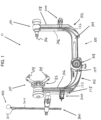
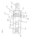
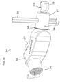
- FIG. 1 illustrates an exemplary HFD (10) in the form of a skull clamp (100) having two clamps (200) and a navigation adapter (300) attached.
- the skull clamp (100) itself comprises two arms (102) that each have a lateral portion (104) and an upright portion (106).
- the lateral portion (104) of one of the arms (102) is configured to receive the lateral portion (104) of the other of the arms (102).
- one of the lateral portions (104) includes a starburst interface (108) for connecting the skull clamp (100) with another structure, e.g., an OR table (not shown).
- the skull clamp (100) can be connected directly to the OR table or indirectly via, e.g., a position adapter (not shown).
- each arm's upright portion (106) is a skull pin assembly (110) that can either be have one or more skull pins connected thereto.
- one upright portion (106) includes a rocker arm (112) with dual skull pins (114), while the other upright portion (106) includes a skull pin assembly (110) having a single skull pin (116).
- Each upright portion (106) of an arm (102) is configured with an integrated rail (118) where the profile of the upright portion (106) defines rail (118).
- Integrated rail (118) in the present example takes the form of an I-beam or similar form.
- rail (118) is configured to receive one or more accessories, e.g., navigation adapter (300), clamps (200), or other accessories.
- HFD (10) includes clamp (200) on each rail (118) and navigation adapter (300) on one of rails (118).
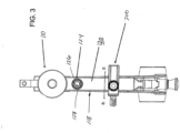
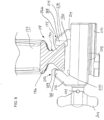
- FIGS. 2-3 illustrate HFD (10), but shown without navigation adapter (300) so as to present more details of rails (118) and clamps (200).
- Rails (118) in the present example have an outer surface (120) with a width of about 25 mm.
- the dimensions of rails (118) can be larger or smaller that those shown and described in the illustrated version.
- rails (118) are configured as straight in the illustrated version, extending generally along the length of upright portions (106), but generally not extending along the length of transitional curves (122) from upright portions (106) to lateral portions (104), and not extending along lateral portions (104) themselves.
- rails (118) can be configured as curved along any portions of upright portions (106), transitional curves (122), and lateral portions (104).
- FIG. 3 illustrates a view that shows rails (118) comprise starburst interface (124) (also referred to at times as a "starburst feature") on outer surface (120) of each rail (118).
- Starburst interface (124) is configured as an accessory attachment interface such that various accessories or other components can be mounted to starburst interface (124).
- starburst interface (124) is positioned generally near the upper portion of rail (118) below skull pin assemblies (110).
- starburst interface (124) is positioned along an upper portion of arm (102) substantially proximal or adjacent to a stabilizing feature that is configured to contact a patient's head, e.g., skull pin assemblies (110) with skull pins (114).
- starburst interface (124) Positioning starburst interface (124) near the upper portion of rail (118) allows for starburst interface (124), and whatever accessory is mounted thereto, to be close to the patient's head and/or close to the points where skull clamp (100) connects with or contacts the patient's head.
- starburst interface (124) is mounted to, connected with, or part of HFD (10) in such a way that starburst interface (124) is close to the patient's head and/or close to the points where the patients head contacts the HFD.
- starburst interfaces (124) can be in other positions along rails (118).
- Starburst interfaces (124) comprise teeth (126) that extend in a circular fashion, where teeth (126) are configured to engage teeth of a complementary starburst interface, e.g. the complementary starburst interface on navigation adapter (300) as will be described further below.
- Starburst interfaces (124) on rail (118) further comprise threaded bore (128) near the center, where threaded bore (128) is configured to engage a bolt, screw, or rod having corresponding threads, where the bolt, screw, or rod can be a component of the complementary starburst interface.
- starburst interface (124) on rail (118) is used as a connection point for navigation adapter (300).
- any variety of accessories could be used with starburst interface (124).
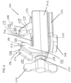
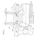
- FIGS. 4-8 illustrate one of clamps (200) depicted in FIG. 1 , the other clamp (200) having the same structure and function.
- clamp (200) comprises a body (202), an actuator (204) in the form of a winged member, a threaded rod (206), a starburst interface (208), a rail (210), dual stationary jaws (212) that are formed integral with body (202), and a single movable jaw (214).
- rotating actuator (204) turns threaded rod (206) in place.
- Single movable jaw (214) comprises a threaded bore (216) positioned about threaded rod (206) such that the threads of threaded bore (216) engage the threads of threaded rod (206).
- movable jaw (214) When actuator (204) is rotated, movable jaw (214) is prevented from rotating based on the configuration of body (202), which comprises a channel (218) that houses threaded rod (206), and body (202) also includes sidewalls (220) that contact movable jaw (214) to prevent it from rotating. Without the ability to rotate in unison with threaded rod (206) and actuator (204), movable jaw (214) translates linearly along threaded rod (206) in response to rotation of actuator (204) based on the engagement between threaded rod (206) and threaded bore (216).
- body (202) comprises bore (230) through which threaded rod (206) extends.
- Actuator (204) comprises bore (232), pin (234), collar (236), and washer (237).
- Collar (236) comprises flange (238) that is positioned adjacent the outer surface of body (202) around bore (230). The remainder of collar (236) generally fits within bore (230). Washer (237) is positioned adjacent the inner surface of body (202) around bore (230).
- Collar (236) further comprises bore (240) such that bore (230) of body (202) and bore (240) of collar (236) are generally concentric.
- Threaded rod (206) extends through bores (230, 240, 232) and pin (234) extends laterally through actuator (204) and through an end portion of threaded rod (206) to retain threaded rod (206) within actuator (204).
- threaded rod (206) comprises flange (242) that generally is adjacent washer (237) within body (202). This configuration described above allows for threaded rod (206) and actuator (204) to rotate in unison, and also allows actuator (204) and threaded rod (206) to maintain their lateral positions relative to body (202) such that when rotated, threaded rod (206) and actuator (204) rotate in place and do not translate laterally.
- bore (232) of actuator (204) is threaded and engages the end of threaded rod (206) with a threaded engagement. Once pin (234) is placed, in such versions, rotation of actuator (204) cannot cause the threaded engagement of actuator (204) and threaded rod (206) to be undone.
- threaded rod (206) comprises end (244) opposite the end of threaded rod (206) that joins with actuator (204). End (244) is configured with threaded bore (248) to accept screw (246) that has complementary threads. Screw (246) is sized such that a lip (254) extends past the diameter of threaded rod (206). Lip (254) is sized such that it is slightly larger than the diameter of bore (216) of movable jaw (214) such that when clamp (200) is opened fully, the end of movable jaw (214) abuts lip (254) of screw (246) thereby retaining movable jaw (214) within body (202).
- starburst interface (208) Positioned on an outer surface (222) of clamp (200) is starburst interface (208) and rail (210).
- rail (210) merges with starburst interface (208).
- Both rail (210) and starburst interface (208) on clamp (200) provide locations for attaching other components or accessories, e.g., retractors, etc.
- Starburst interface (208) on clamps (200) comprises teeth (224) that surround a central threaded bore (226). Teeth (224) and threaded bore (226) are configured to engage with a complementary starburst interface the same or similar to those described above.
- Starburst interface (208) positioned on clamp (200) also comprises sides (228) having flat surfaces.
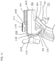
- FIGS. 9 and 10 illustrate a sequence of attaching clamp (200) to rail (118) and also illustrate the cross section profile of arms (102) and integrated rails (118) as well as the void space or shape defined by jaws (212, 214) of clamp (200).
- clamp (200) is tightened, the complementary profile of rail (118) and that defined by jaws (212, 214) of clamp (200) causes clamp (200) to draw itself closer and closer to outer surface (120) of rail (118). This continues until outer surface (120) of rail (118) substantially contacts an inner surface (250) of clamp (200). In this position, as shown in FIGS.
- clamp (200) provides at least a general four-point security or fixation, with each of two stationary jaws (212) contacting rail (118), one movable jaw (214) contacting rail (118), and inner surface (250) of clamp (200) contacting outer surface (120) of rail (118).
- fixation along points of contact is included as well as fixation along surfaces of contact. It should also be understood that at least four-point security or fixation means four or more points of fixation. Similarly, at least three points of fixation or at least three-point fixation means three or more points of fixation.
- dual jaws (212) can be replaced with a single jaw (212).
- FIGS. 9 and 10 are applicable to depict a two total jaw configuration with one fixed jaw (212) and one movable jaw (214).
- clamp (200) provides at least a general three-point security or fixation. This may include fixation at the ends of a three jaw system, or fixation at the ends of a two jaw system with also contact along inner surface (250) of clamp (200) and outer surface (120) of rail (118).
- other configurations of jaws (212, 214) and surfaces (120, 250) of clamp (200) and rail (118) to achieve at least three point fixation will be apparent to one of ordinary skill in the art.
- each rail (118) comprises outer surface (120), inner surface (132), and middle portion (130).
- Middle portion (130) is a narrow width portion of rail (118) and extending from each side of middle portion (130) are outer protrusion (134) and inner protrusion (136) respectively.
- protrusions (134, 136) generally have a triangular dovetail-like shape. More specifically, however, protrusions (134, 136) do not have identical shapes as seen in the illustrated version.
- protrusions (134, 136) can have identical shapes.
- inner surface (132) has a greater width than outer surface (120) such that inner protrusion (136) has a greater width than outer protrusion (134).
- the distance from the center point of middle portion (130) to inner surface (132) is less than the distance from the center portion of middle portion (130) to outer surface (120). This difference in distances contributes to inner protrusion (136) having a flatter profile where it extends a lesser distance from middle portion (130) compared to outer protrusion (134), which has a less flat profile and extends a greater distance from middle portion (130). Referring to FIGS.
- jaws (212, 214) of clamp (200) when jaws (212, 214) of clamp (200) are fully engaged with rail (118), the void space or shape defined by jaws (212, 214) matches the profile of outer protrusion (134) of rail (118) such that clamp (200) securely engages rail (118).
- the shape defined by jaws (212, 214) of clamp (200) is adjustable and can be configured to substantially match, or even exactly match, the cross sectional profile of the structure.jaws (212, 214) are being mounted to.
- jaws (212) comprise ends (256). Ends (256) each comprise tapered surfaces (258, 259) on each side of each jaw (212), where tapered surfaces (258) extend outwardly from inner surfaces (260) on each side of each jaw (212) to end surfaces (262) of jaws (212). Similarly tapered surfaces (259) extend inwardly from outer surfaces (261) on each side of each jaw (212) to end surfaces (262) of jaws (212). Jaws (212) further comprise inclined surfaces (264) that are configured to contact outer protrusion (134) when clamp (200) is engaged with rail (118). End surfaces (262) extend outwardly away from threaded rod (206) in a generally perpendicular fashion. When clamp (200) is fully engaged with rail (118), end surfaces (262) are generally adjacent to middle portion (130) of rail (118).
- jaw (214) comprises end (266).
- End (266) comprises tapered surfaces (268) on each side of jaw (214), where tapered surfaces (268) extends inwardly from outer surfaces (270) of jaw (214) to end surface (272) of jaw (214).
- Jaw (214) further comprises inclined surface (274) that is configured to contact outer protrusion (134) when clamp (200) is engaged with rail (118).
- End surface (272) extends outwardly away from threaded rod (206) in a generally perpendicular fashion. When clamp (200) is fully engaged with rail (118), end surface (272) is generally adjacent to middle portion (130) of rail (118).
- rail (118) is sized such that end surfaces (262, 272) contact middle portion (130) of rail when clamp (200) is fully engaged with rail (118).
- clamp (200) maintains generally at least a seven point security or fixation with rail (118) via contact between: (a) rail (118) and each of three end surfaces (262, 272) of jaws (212, 214), (b) rail (118) and each of three inclined surfaces (264, 274) of jaws (212, 214), and (c) rail (118) and inner surface (250) of clamp (200).
- jaw (214) can be replaced by a component having two jaw members instead of one such that clamp (200) comprises a total of four jaws.
- other modifications to clamp (200) and jaws (212, 214) will be apparent to those of ordinary skill in the art.
- FIG. 12 illustrates an exemplary version where clamp (200) as described above, is used with, and compatible with, a smaller rail (138).
- rail (138) has a smaller size
- outer surface (140) of rail (138) does not contact inner surface (250) of clamp (200) when clamp (200) is secured to rail (138).
- each of three jaws (212, 214) of clamp (200) contact rail (138) at at least two points along the profile of rail (138).
- rail (138) has an I-beam profile generally, and when secured, each jaw (212, 214) of clamp (200) contacts at least two portions of rail (138).
- clamp (200) maintains at least nine points of security or fixation with rail (138) as shown by contact between: (a) rail (138) and each of three end surfaces (262, 272) of jaws (212, 214), (b) rail (138) and each of three inclined surfaces (264, 274) of jaws (212, 214), and (c) rail (138) and each of three upper surfaces (276, 278) of jaws (212, 214).
- ends (256, 266) of jaws (212, 214) are shaped to match the void space defined by the cross sectional profile of rail (138).
- dual jaws (212) may be replaced by a single jaw (212) for an overall two jaw system used with rail (138).
- single jaw (214) may be replaced by a dual jaw configuration to provide an overall four jaw system used with rail (138).
- other ways to modify clamp (200) and rails (118, 138) such that clamp (200) will function with rails of various sizes and/or shapes will be apparent to those of ordinary skill in the art.
- clamp (200) and rail (118) With the configuration of clamp (200) and rail (118) as described above, an automatic alignment of clamp (200) to rail (118) during tightening is provided that ensures full seating of clamp (200) to rail (118) during securing clamp (200) to rail (118).
- the linear movement of jaw (214) to effectuate securing clamp (200) to rail (118), along with the dovetail-like shape of protrusion (134) and complementary shape of void space or shape defined by jaws (212, 214) provides that clamp (200) pulls itself toward rail (118) during tightening. This promotes that jaws (212, 214) contact rail (118) in such a way that jaws (212, 214) are aligned and therefore will fully seat when secured to rail (118).
- This configuration further provides for a repeatable closure of clamp (200), and when secured to rail (118), the connection between clamp (200) and rail (118) is repeatable and stable.
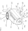
- FIGS. 13-15 illustrate an exemplary navigation adapter (300) comprising body (301).
- navigation adapter (300) connects with rail (118) of HFD (10) at one end via starburst interface (302) and complementary starburst interface (124) as described above.
- starburst interface (302) Associated with starburst interface (302), as shown in FIG. 14 are threaded rod (352), pin (353), actuator (354), and washers (355, 356).
- Actuator (354) is configured to rotate in unison with threaded rod (352), which engages threaded bore (128) of starburst interface (124) to draw the teeth of starburst interfaces (302, 124) together.
- the engagement between starburst interfaces (302, 124) selectively secures navigation adapter (300) to HFD (10).
- navigation adapter (300) can be rotated about starburst interfaces (302, 124) to orient navigation adapter (300) in a desired position.
- the connection between starburst interfaces (124, 302) provides navigation adapter (300) with a first axis of rotation for adjusting the position of navigation adapter (300) relative to skull clamp (100).
- navigation adapter is configured to retain a tracking device (400) (also at times referred to as a reference device or a reference marker) supported by post (304).
- Post (304) comprises connector (305) at the top, and connector (305) connects with the tracking device (400).
- tracking devices are configured to provide spatial data by serving as a reference to any instrument or marker that may be used in conjunction with navigation systems.
- tracking device (400) can be configured to be maintained in the same location throughout a procedure as an instrument or marker moves within the three dimensional space. With such navigation systems, both tracking device (400) and any instrument or marker used in the procedure are communicating with the navigation system.
- Post (304) is adjustable vertically relative to a longitudinal axis defined by body (301) of navigation adapter (300). Also, post (304) can be adjusted rotationally via starburst interfaces (306, 308) that join the portion of navigation adapter (300) that retains post (304) with the remainder of navigation adapter (300). Thus, the connection between starburst interfaces (306, 308) provides navigation adapter (300) with a second axis of rotation for adjusting the position of navigation adapter (300) relative to skull clamp (100). In the present example, as described further below, post (304) is adjustable vertically and rotationally by manipulating a single actuator (316).
- body (301) of navigation adapter (300) comprises pins (357) that retain certain portions of navigation adapter (300) within body (301).
- pins (357) function to retain starburst interfaces (302) and (306) within body (301) of navigation adapter (300).
- starburst interfaces (302, 306) comprise threaded ends (359) that engage body (301) with a threaded engagement instead of or in addition to being retained by pins (357).
- the portion of navigation adapter (300) that retains post (304) comprises inner body (310), middle body (312), outer body (314), and actuator (316).
- Inner body (310) fits within middle body (312) and those fit within outer body (314) such that openings (328, 330, 332) for post (304) can be aligned.
- Middle body (312) includes threaded bore (318) configured to engage with the threads on threaded rod (320), which connects to actuator (316).
- Threaded rod (320) comprises flange (334), and when assembled, flange (334) is adjacent o-ring (336) within middle body (312) as best seen in FIG. 15 .
- threaded rod (320) is inserted through middle body (312) and outer body (314) from the end closest to starburst interface (306).
- Threaded rod (320) is held within actuator (316) by pin (317) that extends through bore (315) of actuator (316) and bore (319) in threaded rod (320) such that rotation of actuator (316) produces corresponding rotation of threaded rod (320).
- First spring (322) is positioned between one end of middle body (312) and outer body (314) as shown in FIGS. 14 and 15 .
- Second spring (324) is positioned between the end of inner body (310) nearest starburst interface (306) and extends within interior bore (326) of starburst interface (306) abutting ring (360).
- Inner body (310) and middle body (312) are configured with lateral slots (338, 340) while outer body (314) includes lateral bore (342).
- Pin (344) connects with bore (342) of outer body (314) and extends through slots (338, 340) of middle body (312) and inner body (310).
- lateral slot (338) of inner body (310) is configured with an intersecting bore (362) that extends laterally through inner body (310).
- pin (344) when pin (344) seats within slot (338), pin (344) can extend at least partially or be extended at least partially within intersecting bore (362). In some other versions, when pin (344) seats within slot (338), pin (344) extends only within the lateral portion of slot (338) and not within intersecting bore (362).
- lateral movement of inner body (310) will produce lateral movement of pin (344) by pin (344) contacting a portion of lateral slot (338) that is closest to threaded rod (320) after sufficient lateral movement of inner body (310).
- middle body (312) remains stationary even when inner body (310), pin (344), and outer body (314) move laterally because pin (344) moves within slot (340) of middle body (312) and because of the specific configuration of middle body (312) as described further below.
- Middle body (312) comprises flange (346) that abuts notch (358) within the sidewall of interior bore (326) of starburst interface (306). Flange (346) further abuts spacer (361) and thus middle body (312) remains stationary because of this contact between flange (346) and notch (358) on one side, and flange (346) and spacer (361) on the other side.
- threaded rod (320) translates toward inner body (310) and drives inner body (310) toward starburst interface (306).
- Slot (338) in inner body (310) is sized and configured as described above so that during at least a portion of the translation or lateral movement of inner body (310), inner body (310) will drive pin (344) in the same direction, thereby moving outer body (314) in the same direction because of the engagement of pin (344) with bore (342) of outer body (314).
- This movement of outer body (314) is such that teeth (348) of starburst interface (308) on outer body (314) engage teeth (350) of starburst interface (306) on body (301) of navigation adapter (300). This action selectively secures the rotational position of the post-retaining portion of navigation adapter (300).
- actuator (315) rotation is reversed to drive threaded rod (320) away from inner body (310).
- the spring bias of springs (322, 324) then causes springs (322, 324) to disengage starburst interface (308) from starburst interface (306) so rotational adjustment can be accomplished.
- Post (304) extends through generally concentric openings (328, 330, 332) in inner body (310), middle body (312), and outer body (314) respectively.
- inner body (310) and outer body (314) translate, post (304) is pushed in the same direction as the translation.
- Middle body (312) remains stationary as does its oblong shaped opening (330) through which post (304) passes. Therefore, the translation of inner body (310) and outer body (314) push post (304) against the side of opening (330) in middle body (312) that is closest to body (301) of navigation adapter (300).
- post (304) is pushed from the opposite side by its contact with openings (328, 332) of inner body (310) and outer body (314) respectively.
- These forces and contact create an interference fit or connection between post (304) and openings (328, 330, 332) in inner body (310), middle body (312), and outer body (314) respectively, such that the vertical position of post (304) is selectively secured.
- the reverse motion of actuator (316) will cause the components to resiliently move back due to the spring bias of springs (322, 324), and then vertical adjustment of post (304) can be accomplished.
- the present version shows that the interface for connecting navigation adapter (300) to HFD (10)-in this case starburst interface (124)-is positioned relatively close to the skull pin assembly (110) and associated skull pins (114) that would ultimately engage a patient's head.
- the interface for the navigation adapter (300) is close to the structures that will be used to stabilize the patient's head.
- the interface and the configuration of navigation adapter (300) itself are such that navigation adapter (300) can be positioned close to a patient's head, while not interfering with the structures that will be used to stabilize the patient's head or the operation of those structures.
- navigation adapter (300) is positionable such that it angles away from the skull clamp (100) such that navigation adapter (300) is generally not coplanar with either skull pin assemblies (110) or arms (102) of skull clamp (100). This contributes to navigation adapter (300) not interfering with such components of skull clamp (100) like skull pin assemblies (110), clamps (200), and other components.
- incorporating starburst interface (124) relatively near the upper portion of arm (102), allows the components of attached navigation adapter (300) to extend for a shorter distance to appropriately position tracking device (400).
- the distance through navigation adapter (300) itself, from the starting point at the connection with starburst (124) to the ending point at connector (305) or tracking device (400) is less or shorter than this distance with other configurations where a navigation adapter attaches lower on the skull clamp (100).
- a navigation adapter connects to starburst (108)
- the components of that navigation adapter extend for a longer distance to ultimately position tracking device (400) appropriately near the patient's head.
- navigation adapter (300) ranges between about 15 to 25 centimeters in cumulative length through navigation adapter (300) as described above.
- the components described herein can be made of imagining compatible materials, like aluminum or titanium among others. Of course where imaging is not a concern, the components can be made of other metals that would not necessarily be compatible with imaging modalities. Still yet, the components in some versions are made of radiolucent materials to not only be compatible with imaging modalities, but also provide little or no artifacts or imaging signature when imaging is performed. In view of the teachings herein, other materials of construction for the components described will be apparent to those of ordinary skill in the art.
Landscapes
- Health & Medical Sciences (AREA)
- Surgery (AREA)
- Life Sciences & Earth Sciences (AREA)
- Biomedical Technology (AREA)
- Medical Informatics (AREA)
- Oral & Maxillofacial Surgery (AREA)
- Nuclear Medicine, Radiotherapy & Molecular Imaging (AREA)
- Engineering & Computer Science (AREA)
- Veterinary Medicine (AREA)
- Heart & Thoracic Surgery (AREA)
- Pathology (AREA)
- Molecular Biology (AREA)
- Animal Behavior & Ethology (AREA)
- General Health & Medical Sciences (AREA)
- Public Health (AREA)
- Neurosurgery (AREA)
- Accommodation For Nursing Or Treatment Tables (AREA)
- Surgical Instruments (AREA)
Claims (6)
- Eine Kopffixierungsvorrichtung (10) in Form einer Schädelklemme (100) zur Verwendung in einem medizinischen Verfahren, wobei die Kopffixierungsvorrichtung (10) aufweist:a. ein Paar Arme (102), die die Schädelklemme (100) definieren, wobei jeder des Paares von Armen (102) einen aufrechten Abschnitt (106) und einen seitlichen Abschnitt aufweist, wobei jeder der Arme (102) ein Querschnittsprofil aufweist, das eine Schiene (118) definiert;b. ein Paar von Stabilisierungselementen (110), die jeweils mit einem der aufrechten Abschnitte des Paars von Armen (102) verbunden sind, die die Schädelklemme (100) definieren, wobei die Stabilisierungselemente (110) so konfiguriert sind, dass sie punktuell den Kopf eines Patienten berühren; undc. eine Zubehöranbringungsschnittstelle (124), die konfiguriert ist, ein erstes Zubehörteil zur Verwendung während des medizinischen Verfahrens aufzunehmen, wobei die Zubehöranbringungsschnittstelle (124) entlang des aufrechten Abschnitts (106) eines des Paars von Armen (102), die die Schädelklemme (100) definieren, positioniert ist, wobei die Zubehöranbringungsschnittstelle (124) proximal oder benachbart zu dem Stabilisierungselement (110) positioniert ist;wobei die Zubehörbefestigungsschnittstelle (124) Teil der Kopffixierungsvorrichtung (10) ist,wobei die Schiene (118) eine Außenfläche aufweist, wobei die Zubehörbefestigungsschnittstelle (123) an der Außenfläche der Schiene (118) angeordnet ist.
- Kopffixierungsvorrichtung (10) nach Anspruch 1, wobei die Zubehöranbringungsschnittstelle (124) eine Starburst-Schnittstelle aufweist.
- Kopffixierungsvorrichtung nach einem der vorhergehenden Ansprüche, wobei die Schiene (118, 138) aufweist:a. mindestens ein vorstehendes Element (134); undb. die Zubehöranbringungsschnittstelle (124);wobei das vorstehende Element (134) konfiguriert ist, ein zweites Zubehörteil zur Verwendung während des medizinischen Eingriffs aufzunehmen.
- Kopffixierungsvorrichtung (10) nach einem der vorhergehenden Ansprüche, wobei das erste Zubehörteil ein Navigationsadapter (300) ist, der von der Kopffixierungsvorrichtung (10) umfasst ist.
- Kopffixierungsvorrichtung (10) nach Anspruch 4, wobei sich der Navigationsadapter (300) von der Schiene (118, 138) nach außen erstreckt, so dass der Navigationsadapter (300) im Wesentlichen nicht koplanar mit dem Stabilisierungselement ist.
- Kopffixierungsvorrichtung (10) nach Anspruch 5, wobei der Navigationsadapter (300) um zwei Rotationsachsen einstellbar ist und außerdem vertikal relativ zu einer Längsachse, die durch einen Körper des Navigationsadapters (300) definiert ist, einstellbar ist.
Applications Claiming Priority (2)
| Application Number | Priority Date | Filing Date | Title |
|---|---|---|---|
| US201161542246P | 2011-10-02 | 2011-10-02 | |
| EP12006851.5A EP2574301B1 (de) | 2011-10-02 | 2012-10-02 | Kopffixiervorrichtung und vorrichtung zur befestigung von komponenten daran |
Related Parent Applications (1)
| Application Number | Title | Priority Date | Filing Date |
|---|---|---|---|
| EP12006851.5A Division EP2574301B1 (de) | 2011-10-02 | 2012-10-02 | Kopffixiervorrichtung und vorrichtung zur befestigung von komponenten daran |
Publications (3)
| Publication Number | Publication Date |
|---|---|
| EP3120799A1 EP3120799A1 (de) | 2017-01-25 |
| EP3120799B1 true EP3120799B1 (de) | 2024-12-04 |
| EP3120799B8 EP3120799B8 (de) | 2025-08-27 |
Family
ID=47010161
Family Applications (2)
| Application Number | Title | Priority Date | Filing Date |
|---|---|---|---|
| EP16001885.9A Active EP3120799B8 (de) | 2011-10-02 | 2012-10-02 | Kopffixiervorrichtung und einrichtung zur sicherung von komponenten daran |
| EP12006851.5A Active EP2574301B1 (de) | 2011-10-02 | 2012-10-02 | Kopffixiervorrichtung und vorrichtung zur befestigung von komponenten daran |
Family Applications After (1)
| Application Number | Title | Priority Date | Filing Date |
|---|---|---|---|
| EP12006851.5A Active EP2574301B1 (de) | 2011-10-02 | 2012-10-02 | Kopffixiervorrichtung und vorrichtung zur befestigung von komponenten daran |
Country Status (2)
| Country | Link |
|---|---|
| US (1) | US9402692B2 (de) |
| EP (2) | EP3120799B8 (de) |
Families Citing this family (34)
| Publication number | Priority date | Publication date | Assignee | Title |
|---|---|---|---|---|
| US9833289B2 (en) | 2009-02-26 | 2017-12-05 | pro med instruments, GmbH | Method and apparatus for a radiolucent and MRI compatible cranial stabilization pin |
| US9308050B2 (en) | 2011-04-01 | 2016-04-12 | Ecole Polytechnique Federale De Lausanne (Epfl) | Robotic system and method for spinal and other surgeries |
| US10682196B2 (en) | 2011-10-02 | 2020-06-16 | Pro Med Instruments Gmbh | Head fixation device and apparatus for securing components thereto |
| DE102012214449B4 (de) * | 2012-08-14 | 2014-07-10 | Siemens Aktiengesellschaft | Patientenlagerungsvorrichtung sowie eine die Patientenlagerungsvorrichtung umfassende medizinische Bildgebungsvorrichtung |
| US10231798B2 (en) | 2012-11-09 | 2019-03-19 | Pro Med Instruments Gmbh | Skull clamp opening apparatus and method |
| US9283048B2 (en) | 2013-10-04 | 2016-03-15 | KB Medical SA | Apparatus and systems for precise guidance of surgical tools |
| US9788900B2 (en) | 2013-11-26 | 2017-10-17 | Pro Med Instruments Gmbh | Surgical instrument positioning system and method |
| US10039605B2 (en) | 2014-02-11 | 2018-08-07 | Globus Medical, Inc. | Sterile handle for controlling a robotic surgical system from a sterile field |
| US10595744B2 (en) * | 2014-02-14 | 2020-03-24 | MRI Interventions, Inc. | Surgical tool-positioning devices and related methods |
| EP3134022B1 (de) | 2014-04-24 | 2018-01-10 | KB Medical SA | Halter für ein chirurgisches instrument zur verwendung mit einem chirurgischen robotersystem |
| USD810304S1 (en) * | 2014-04-24 | 2018-02-13 | Cefla Societá Cooperativa | Head support |
| US20160015459A1 (en) * | 2014-04-28 | 2016-01-21 | Jeffrey A. Greenberg | Neuro-Surgical Clamp |
| US10285732B2 (en) * | 2014-05-16 | 2019-05-14 | Pro Med Instruments Gmbh | Skull clamp |
| WO2015193479A1 (en) | 2014-06-19 | 2015-12-23 | KB Medical SA | Systems and methods for performing minimally invasive surgery |
| US9808322B2 (en) * | 2014-08-27 | 2017-11-07 | Vito Del Deo | Method and device for positioning and stabilization of bony structures during maxillofacial surgery |
| WO2016087539A2 (en) | 2014-12-02 | 2016-06-09 | KB Medical SA | Robot assisted volume removal during surgery |
| WO2016125013A2 (en) | 2015-02-05 | 2016-08-11 | Pro Med Instruments Gmbh | System and method for invasive and non-invasive head fixation |
| US10271914B2 (en) | 2015-02-11 | 2019-04-30 | University Of Utah Research Foundation | Microsurgical tool adapters, systems and related methods |
| WO2016131903A1 (en) | 2015-02-18 | 2016-08-25 | KB Medical SA | Systems and methods for performing minimally invasive spinal surgery with a robotic surgical system using a percutaneous technique |
| WO2017037127A1 (en) | 2015-08-31 | 2017-03-09 | KB Medical SA | Robotic surgical systems and methods |
| DE102016004231A1 (de) * | 2016-04-08 | 2017-10-12 | Cival Medical Gmbh | Chirurgische Schädelklemme |
| DE102017006903B4 (de) * | 2016-07-22 | 2024-10-31 | Pro Med Instruments Gmbh | Kopffixierungsgerät und Vorrichtung zum Sichern von Komponenten hieran |
| CN110353931A (zh) * | 2018-05-28 | 2019-10-22 | 徐晓胜 | 一种外科手术用辅助固定装置 |
| CN108852734A (zh) * | 2018-07-31 | 2018-11-23 | 重庆医科大学附属第三医院(捷尔医院) | 整形美容颌面部固定装置 |
| CN109700531B (zh) * | 2018-12-17 | 2021-07-30 | 上海交通大学医学院附属第九人民医院 | 个体化下颌骨导航配准导板及其配准方法 |
| CN109607197A (zh) * | 2018-12-21 | 2019-04-12 | 武汉安比克科技有限公司 | 一种高精度智能送料工装 |
| EP4477182B1 (de) * | 2019-01-10 | 2026-03-04 | pro med instruments GmbH | Kipphebelanordnung für kopffixierungsvorrichtung |
| CN109984909A (zh) * | 2019-04-30 | 2019-07-09 | 遵义市红花岗区人民医院 | 一种脑外科用手术固定装置 |
| WO2021009562A1 (en) | 2019-07-15 | 2021-01-21 | Pro Med Instruments Gmbh | Stabilization assembly for head fixation device |
| EP3903713B1 (de) | 2020-04-29 | 2024-08-21 | Stryker European Operations Limited | Feldgeneratoranordnung für chirurgische navigation |
| CN112006785A (zh) * | 2020-09-01 | 2020-12-01 | 郑州大学第一附属医院 | 一种颅脑损伤保护装置 |
| JP2024539113A (ja) * | 2021-10-18 | 2024-10-28 | ストライカー・ユーロピアン・オペレーションズ・リミテッド | 外科用器具を追跡するアタッチメント及びシステム |
| WO2024067298A1 (zh) * | 2022-09-28 | 2024-04-04 | 宁波大学附属第一医院 | 带有长度可调整连接器的头架、固定连接器 |
| USD1091816S1 (en) | 2023-04-19 | 2025-09-02 | Stryker European Operations Limited | Surgical instrument tracker |
Citations (1)
| Publication number | Priority date | Publication date | Assignee | Title |
|---|---|---|---|---|
| EP2736440B1 (de) * | 2011-07-28 | 2016-10-05 | Brainlab AG | Patientenpositionierungssystem mit einem elektromagnetischen feldgenerator eines elektromagnetischen trackingsystems |
Family Cites Families (50)
| Publication number | Priority date | Publication date | Assignee | Title |
|---|---|---|---|---|
| US1839726A (en) | 1930-08-01 | 1932-01-05 | Hubert R Arnold | Circular retractor |
| US2586488A (en) | 1949-05-11 | 1952-02-19 | David P Smith | Table supported surgical retractor |
| US2594086A (en) | 1950-04-29 | 1952-04-22 | David P Smith | Table supported abdominal retractor |
| US3522799A (en) | 1967-06-21 | 1970-08-04 | William K Gauthier | Surgical retractor device |
| US3835861A (en) | 1972-12-08 | 1974-09-17 | Kees Surgical Specialty Co | Surgical head clamp |
| US4169478A (en) * | 1978-03-15 | 1979-10-02 | Ohio Medical Instrument Company, Inc. | Surgical head clamp |
| ES253459Y (es) | 1978-11-10 | 1982-04-16 | Fijador clinico externo, de elevada estabilidad, para reduc-cion de fracturas. | |
| US4543947A (en) | 1980-10-28 | 1985-10-01 | Blackstone Ralf W | Cervical spine collar |
| US4392645A (en) | 1981-05-28 | 1983-07-12 | Westphal Thomas R | Head support and halo jig |
| US4457300A (en) | 1982-06-07 | 1984-07-03 | Ohio Medical Instrument Co., Inc. | Surgical retractor |
| DE3302312A1 (de) | 1983-01-25 | 1984-07-26 | Karl Lautenschläger KG, Möbelbeschlagfabrik, 6107 Reinheim | Moebelscharnier |
| US4539979A (en) | 1983-04-27 | 1985-09-10 | Bremer Orthopedics, Inc. | Temporary cervical traction maintenance |
| US4541421A (en) | 1984-04-03 | 1985-09-17 | Pmt, Inc. | Halo fixation system |
| US4667660A (en) | 1985-02-19 | 1987-05-26 | Ace Medical Company | Universal orthopedic traction tongs assembly |
| CH671873A5 (de) | 1985-10-03 | 1989-10-13 | Synthes Ag | |
| US4807605A (en) | 1986-12-16 | 1989-02-28 | Mattingly Leslie G | Halo traction brace |
| US4796846A (en) | 1987-06-01 | 1989-01-10 | Automated Medical Products, Corporation | Retaining device for a surgical instrument |
| US4827926A (en) | 1987-06-30 | 1989-05-09 | Carol Mark P | Flexible support arm for medical instruments |
| US4838264A (en) | 1987-08-18 | 1989-06-13 | Bremer Orthopedics, Inc. | Torque limiting device for use with bone penetrating pins |
| US4971037A (en) | 1988-09-19 | 1990-11-20 | Pilling Co. | Surgical retractor support |
| US5203765A (en) | 1991-05-31 | 1993-04-20 | Friddle Orthopedic Appliances, Inc. | Adjustable halo system orthopedic appliance and method |
| US5284129A (en) | 1992-08-28 | 1994-02-08 | Codman & Shurtleff, Inc. | Swivel ring surgical retractor |
| US5276927A (en) | 1992-09-21 | 1994-01-11 | Ohio Medical Instrument Co. | Radiolucent head support |
| US5501685A (en) | 1994-04-26 | 1996-03-26 | Spetzler; Robert F. | Method for securing a cranial piece in position |
| US5954723A (en) | 1994-04-26 | 1999-09-21 | Spetzler; Robert F. | Method and apparatus for securing a cranial plate with pins |
| US5478329A (en) | 1994-05-06 | 1995-12-26 | Ternamian; Artin M. | Trocarless rotational entry cannula |
| US5537704A (en) | 1994-07-19 | 1996-07-23 | Ohio Medical Instrument Company, Inc. | Radiolucent head clamp |
| US5529358A (en) | 1994-09-30 | 1996-06-25 | Ohio Medical Instrument Company | Bifurcated surgical retractor |
| US5891157A (en) | 1994-09-30 | 1999-04-06 | Ohio Medical Instrument Company, Inc. | Apparatus for surgical stereotactic procedures |
| US5971997A (en) * | 1995-02-03 | 1999-10-26 | Radionics, Inc. | Intraoperative recalibration apparatus for stereotactic navigators |
| US5865780A (en) | 1995-10-13 | 1999-02-02 | Sdgi Holdings, Inc. | Transportable cervical immobilization device |
| US5722978A (en) | 1996-03-13 | 1998-03-03 | Jenkins, Jr.; Joseph Robert | Osteotomy system |
| US6110182A (en) | 1998-06-22 | 2000-08-29 | Ohio Medical Instruments Company, Inc. | Target socket |
| US6129729A (en) | 1998-11-11 | 2000-10-10 | Snyder; Samuel J. | Apparatus and method for targeting and/or installing fasteners into an intramedullary nail |
| US6198961B1 (en) | 1998-11-12 | 2001-03-06 | Picker International, Inc. | Interventional radio frequency coil assembly for magnetic resonance (MR) guided neurosurgery |
| ES2220605T3 (es) | 2000-03-03 | 2004-12-16 | Theo J.J. Zegers | Dispositivo de fijacion de la cabeza para fines quirurgicos. |
| US6306146B1 (en) | 2000-04-06 | 2001-10-23 | Ohio Medical Instrument Company, Inc. | Surgical instrument support and method |
| US6659972B2 (en) | 2001-02-02 | 2003-12-09 | Rose-Hulman Institute Of Technology | Halo orthosis |
| US6598275B1 (en) | 2001-03-12 | 2003-07-29 | Steris, Inc. | Low shadow radiolucent surgical table, clamp systems, and accessories therefore |
| USD456510S1 (en) | 2001-04-13 | 2002-04-30 | Allegiance Corporation | Skull clamp |
| US7232411B2 (en) | 2001-04-20 | 2007-06-19 | Integra Lifesciences Corporation | Radiolucent retractor and related components |
| EP1295568A1 (de) | 2001-09-20 | 2003-03-26 | Carl Zeiss | Mit Abdeckvorrichtung versehenes Instrument |
| US7048735B2 (en) | 2002-02-04 | 2006-05-23 | Smith & Nephew | External fixation system |
| EP2151215B1 (de) * | 2002-08-09 | 2012-09-19 | Kinamed, Inc. | Nicht bildgebende Ortungswerkzeuge für eine Hüftoperation |
| US7730563B1 (en) | 2004-03-29 | 2010-06-08 | Frederick Sklar | Head support and stabilization system |
| DE602005023248D1 (de) * | 2004-10-15 | 2010-10-14 | Pro Med Instruments Gmbh | Gerät zur Befestigung von Zusatzgeräten an einer chirurgischen Fixierungseinrichtung |
| DE202006006734U1 (de) * | 2006-04-24 | 2006-06-22 | Gottfried Storz Medizintechnik Gmbh & Co. Kg | Chirurgische Kopfklemme |
| US20100059064A1 (en) | 2008-05-09 | 2010-03-11 | Schuele Edgar Franz | Method and Apparatus for Using a Surgical Fixture in an Intra-Operative Computed Tomography Scanner |
| JP2011522607A (ja) * | 2008-06-05 | 2011-08-04 | ディンクラー・サージカル・デヴァイシズ,インコーポレーテッド | 頭部固定装置 |
| GB0908784D0 (en) * | 2009-05-21 | 2009-07-01 | Renishaw Plc | Apparatus for imaging a body part |
-
2012
- 2012-10-02 EP EP16001885.9A patent/EP3120799B8/de active Active
- 2012-10-02 EP EP12006851.5A patent/EP2574301B1/de active Active
- 2012-10-02 US US13/633,164 patent/US9402692B2/en active Active
Patent Citations (1)
| Publication number | Priority date | Publication date | Assignee | Title |
|---|---|---|---|---|
| EP2736440B1 (de) * | 2011-07-28 | 2016-10-05 | Brainlab AG | Patientenpositionierungssystem mit einem elektromagnetischen feldgenerator eines elektromagnetischen trackingsystems |
Also Published As
| Publication number | Publication date |
|---|---|
| EP2574301A1 (de) | 2013-04-03 |
| EP3120799B8 (de) | 2025-08-27 |
| US20130081636A1 (en) | 2013-04-04 |
| EP3120799A1 (de) | 2017-01-25 |
| US9402692B2 (en) | 2016-08-02 |
| EP2574301B1 (de) | 2016-08-31 |
Similar Documents
| Publication | Publication Date | Title |
|---|---|---|
| EP3120799B1 (de) | Kopffixiervorrichtung und einrichtung zur sicherung von komponenten daran | |
| US20200261179A1 (en) | Head fixation device and apparatus for securing components thereto | |
| US8287537B2 (en) | Head fixation device | |
| US6887198B2 (en) | Gooseneck surgical retractor positioner and method of its use | |
| US7695497B2 (en) | Implant system for osteosynthesis | |
| US20100059064A1 (en) | Method and Apparatus for Using a Surgical Fixture in an Intra-Operative Computed Tomography Scanner | |
| US9381044B2 (en) | Posterior spinal stabilization plate device | |
| US8852090B2 (en) | System and method for retracting body tissue | |
| US8361117B2 (en) | Spinal cross connectors | |
| US10080560B2 (en) | System and method for retracting body tissue | |
| US11096680B2 (en) | Surgical retractor system and method | |
| EP3132767B1 (de) | Schädelklemme und verfahren zur verbindung | |
| US20090105547A1 (en) | Adjustable Retractor Blade | |
| US20110190824A1 (en) | Occipital Plate for Spinal Fusion | |
| US7836532B2 (en) | Method and apparatus for attaching accessories to a surgical fixture | |
| US10285732B2 (en) | Skull clamp | |
| WO2014033542A1 (en) | Table adapter with joint assembly | |
| US12201482B2 (en) | Stabilization assembly for head fixation device | |
| US20250268682A1 (en) | Skull clamp with sagittal adjustment |
Legal Events
| Date | Code | Title | Description |
|---|---|---|---|
| PUAI | Public reference made under article 153(3) epc to a published international application that has entered the european phase |
Free format text: ORIGINAL CODE: 0009012 |
|
| STAA | Information on the status of an ep patent application or granted ep patent |
Free format text: STATUS: THE APPLICATION HAS BEEN PUBLISHED |
|
| AC | Divisional application: reference to earlier application |
Ref document number: 2574301 Country of ref document: EP Kind code of ref document: P |
|
| AK | Designated contracting states |
Kind code of ref document: A1 Designated state(s): AL AT BE BG CH CY CZ DE DK EE ES FI FR GB GR HR HU IE IS IT LI LT LU LV MC MK MT NL NO PL PT RO RS SE SI SK SM TR |
|
| STAA | Information on the status of an ep patent application or granted ep patent |
Free format text: STATUS: REQUEST FOR EXAMINATION WAS MADE |
|
| 17P | Request for examination filed |
Effective date: 20170725 |
|
| RBV | Designated contracting states (corrected) |
Designated state(s): AL AT BE BG CH CY CZ DE DK EE ES FI FR GB GR HR HU IE IS IT LI LT LU LV MC MK MT NL NO PL PT RO RS SE SI SK SM TR |
|
| TPAC | Observations filed by third parties |
Free format text: ORIGINAL CODE: EPIDOSNTIPA |
|
| STAA | Information on the status of an ep patent application or granted ep patent |
Free format text: STATUS: EXAMINATION IS IN PROGRESS |
|
| 17Q | First examination report despatched |
Effective date: 20210527 |
|
| GRAP | Despatch of communication of intention to grant a patent |
Free format text: ORIGINAL CODE: EPIDOSNIGR1 |
|
| STAA | Information on the status of an ep patent application or granted ep patent |
Free format text: STATUS: GRANT OF PATENT IS INTENDED |
|
| INTG | Intention to grant announced |
Effective date: 20240619 |
|
| GRAS | Grant fee paid |
Free format text: ORIGINAL CODE: EPIDOSNIGR3 |
|
| P01 | Opt-out of the competence of the unified patent court (upc) registered |
Free format text: CASE NUMBER: APP_51139/2024 Effective date: 20240910 |
|
| GRAA | (expected) grant |
Free format text: ORIGINAL CODE: 0009210 |
|
| STAA | Information on the status of an ep patent application or granted ep patent |
Free format text: STATUS: THE PATENT HAS BEEN GRANTED |
|
| AC | Divisional application: reference to earlier application |
Ref document number: 2574301 Country of ref document: EP Kind code of ref document: P |
|
| AK | Designated contracting states |
Kind code of ref document: B1 Designated state(s): AL AT BE BG CH CY CZ DE DK EE ES FI FR GB GR HR HU IE IS IT LI LT LU LV MC MK MT NL NO PL PT RO RS SE SI SK SM TR |
|
| REG | Reference to a national code |
Ref country code: GB Ref legal event code: FG4D |
|
| REG | Reference to a national code |
Ref country code: DE Ref legal event code: R081 Ref document number: 602012081252 Country of ref document: DE Owner name: PRO MED INSTRUMENTS GMBH, PART OF BLACK FOREST, DE Free format text: FORMER OWNER: ANMELDERANGABEN UNKLAR / UNVOLLSTAENDIG, 80297 MUENCHEN, DE |
|
| REG | Reference to a national code |
Ref country code: DE Ref legal event code: R081 Ref document number: 602012081252 Country of ref document: DE Owner name: PRO MED INSTRUMENTS GMBH, PART OF BLACK FOREST, DE Free format text: FORMER OWNER: PRO MED INSTRUMENTS GMBH, 79111 FREIBURG, DE Ref country code: CH Ref legal event code: EP |
|
| REG | Reference to a national code |
Ref country code: DE Ref legal event code: R096 Ref document number: 602012081252 Country of ref document: DE |
|
| REG | Reference to a national code |
Ref country code: IE Ref legal event code: FG4D |
|
| REG | Reference to a national code |
Ref country code: LT Ref legal event code: MG9D |
|
| REG | Reference to a national code |
Ref country code: NL Ref legal event code: MP Effective date: 20241204 |
|
| PG25 | Lapsed in a contracting state [announced via postgrant information from national office to epo] |
Ref country code: HR Free format text: LAPSE BECAUSE OF FAILURE TO SUBMIT A TRANSLATION OF THE DESCRIPTION OR TO PAY THE FEE WITHIN THE PRESCRIBED TIME-LIMIT Effective date: 20241204 |
|
| PG25 | Lapsed in a contracting state [announced via postgrant information from national office to epo] |
Ref country code: FI Free format text: LAPSE BECAUSE OF FAILURE TO SUBMIT A TRANSLATION OF THE DESCRIPTION OR TO PAY THE FEE WITHIN THE PRESCRIBED TIME-LIMIT Effective date: 20241204 |
|
| PG25 | Lapsed in a contracting state [announced via postgrant information from national office to epo] |
Ref country code: BG Free format text: LAPSE BECAUSE OF FAILURE TO SUBMIT A TRANSLATION OF THE DESCRIPTION OR TO PAY THE FEE WITHIN THE PRESCRIBED TIME-LIMIT Effective date: 20241204 |
|
| PG25 | Lapsed in a contracting state [announced via postgrant information from national office to epo] |
Ref country code: ES Free format text: LAPSE BECAUSE OF FAILURE TO SUBMIT A TRANSLATION OF THE DESCRIPTION OR TO PAY THE FEE WITHIN THE PRESCRIBED TIME-LIMIT Effective date: 20241204 |
|
| PG25 | Lapsed in a contracting state [announced via postgrant information from national office to epo] |
Ref country code: NO Free format text: LAPSE BECAUSE OF FAILURE TO SUBMIT A TRANSLATION OF THE DESCRIPTION OR TO PAY THE FEE WITHIN THE PRESCRIBED TIME-LIMIT Effective date: 20250304 |
|
| PG25 | Lapsed in a contracting state [announced via postgrant information from national office to epo] |
Ref country code: LV Free format text: LAPSE BECAUSE OF FAILURE TO SUBMIT A TRANSLATION OF THE DESCRIPTION OR TO PAY THE FEE WITHIN THE PRESCRIBED TIME-LIMIT Effective date: 20241204 Ref country code: GR Free format text: LAPSE BECAUSE OF FAILURE TO SUBMIT A TRANSLATION OF THE DESCRIPTION OR TO PAY THE FEE WITHIN THE PRESCRIBED TIME-LIMIT Effective date: 20250305 |
|
| PG25 | Lapsed in a contracting state [announced via postgrant information from national office to epo] |
Ref country code: RS Free format text: LAPSE BECAUSE OF FAILURE TO SUBMIT A TRANSLATION OF THE DESCRIPTION OR TO PAY THE FEE WITHIN THE PRESCRIBED TIME-LIMIT Effective date: 20250304 |
|
| PG25 | Lapsed in a contracting state [announced via postgrant information from national office to epo] |
Ref country code: NL Free format text: LAPSE BECAUSE OF FAILURE TO SUBMIT A TRANSLATION OF THE DESCRIPTION OR TO PAY THE FEE WITHIN THE PRESCRIBED TIME-LIMIT Effective date: 20241204 |
|
| REG | Reference to a national code |
Ref country code: AT Ref legal event code: MK05 Ref document number: 1747305 Country of ref document: AT Kind code of ref document: T Effective date: 20241204 |
|
| PG25 | Lapsed in a contracting state [announced via postgrant information from national office to epo] |
Ref country code: SM Free format text: LAPSE BECAUSE OF FAILURE TO SUBMIT A TRANSLATION OF THE DESCRIPTION OR TO PAY THE FEE WITHIN THE PRESCRIBED TIME-LIMIT Effective date: 20241204 |
|
| PG25 | Lapsed in a contracting state [announced via postgrant information from national office to epo] |
Ref country code: PL Free format text: LAPSE BECAUSE OF FAILURE TO SUBMIT A TRANSLATION OF THE DESCRIPTION OR TO PAY THE FEE WITHIN THE PRESCRIBED TIME-LIMIT Effective date: 20241204 |
|
| PG25 | Lapsed in a contracting state [announced via postgrant information from national office to epo] |
Ref country code: IS Free format text: LAPSE BECAUSE OF FAILURE TO SUBMIT A TRANSLATION OF THE DESCRIPTION OR TO PAY THE FEE WITHIN THE PRESCRIBED TIME-LIMIT Effective date: 20250404 |
|
| PG25 | Lapsed in a contracting state [announced via postgrant information from national office to epo] |
Ref country code: PT Free format text: LAPSE BECAUSE OF FAILURE TO SUBMIT A TRANSLATION OF THE DESCRIPTION OR TO PAY THE FEE WITHIN THE PRESCRIBED TIME-LIMIT Effective date: 20250404 |
|
| PG25 | Lapsed in a contracting state [announced via postgrant information from national office to epo] |
Ref country code: EE Free format text: LAPSE BECAUSE OF FAILURE TO SUBMIT A TRANSLATION OF THE DESCRIPTION OR TO PAY THE FEE WITHIN THE PRESCRIBED TIME-LIMIT Effective date: 20241204 |
|
| PG25 | Lapsed in a contracting state [announced via postgrant information from national office to epo] |
Ref country code: AT Free format text: LAPSE BECAUSE OF FAILURE TO SUBMIT A TRANSLATION OF THE DESCRIPTION OR TO PAY THE FEE WITHIN THE PRESCRIBED TIME-LIMIT Effective date: 20241204 Ref country code: RO Free format text: LAPSE BECAUSE OF FAILURE TO SUBMIT A TRANSLATION OF THE DESCRIPTION OR TO PAY THE FEE WITHIN THE PRESCRIBED TIME-LIMIT Effective date: 20241204 |
|
| PG25 | Lapsed in a contracting state [announced via postgrant information from national office to epo] |
Ref country code: SK Free format text: LAPSE BECAUSE OF FAILURE TO SUBMIT A TRANSLATION OF THE DESCRIPTION OR TO PAY THE FEE WITHIN THE PRESCRIBED TIME-LIMIT Effective date: 20241204 |
|
| PG25 | Lapsed in a contracting state [announced via postgrant information from national office to epo] |
Ref country code: CZ Free format text: LAPSE BECAUSE OF FAILURE TO SUBMIT A TRANSLATION OF THE DESCRIPTION OR TO PAY THE FEE WITHIN THE PRESCRIBED TIME-LIMIT Effective date: 20241204 |
|
| PG25 | Lapsed in a contracting state [announced via postgrant information from national office to epo] |
Ref country code: IT Free format text: LAPSE BECAUSE OF FAILURE TO SUBMIT A TRANSLATION OF THE DESCRIPTION OR TO PAY THE FEE WITHIN THE PRESCRIBED TIME-LIMIT Effective date: 20241204 |
|
| REG | Reference to a national code |
Ref country code: CH Ref legal event code: PK Free format text: BERICHTIGUNG B8 |
|
| RAP4 | Party data changed (patent owner data changed or rights of a patent transferred) |
Owner name: PRO MED INSTRUMENTS GMBH, PART OF BLACK FORESTMEDICAL GROUP |
|
| REG | Reference to a national code |
Ref country code: DE Ref legal event code: R097 Ref document number: 602012081252 Country of ref document: DE |
|
| PG25 | Lapsed in a contracting state [announced via postgrant information from national office to epo] |
Ref country code: SE Free format text: LAPSE BECAUSE OF FAILURE TO SUBMIT A TRANSLATION OF THE DESCRIPTION OR TO PAY THE FEE WITHIN THE PRESCRIBED TIME-LIMIT Effective date: 20241204 |
|
| PG25 | Lapsed in a contracting state [announced via postgrant information from national office to epo] |
Ref country code: DK Free format text: LAPSE BECAUSE OF FAILURE TO SUBMIT A TRANSLATION OF THE DESCRIPTION OR TO PAY THE FEE WITHIN THE PRESCRIBED TIME-LIMIT Effective date: 20241204 |
|
| PLBE | No opposition filed within time limit |
Free format text: ORIGINAL CODE: 0009261 |
|
| STAA | Information on the status of an ep patent application or granted ep patent |
Free format text: STATUS: NO OPPOSITION FILED WITHIN TIME LIMIT |
|
| 26N | No opposition filed |
Effective date: 20250905 |
|
| PGFP | Annual fee paid to national office [announced via postgrant information from national office to epo] |
Ref country code: DE Payment date: 20251029 Year of fee payment: 14 |
|
| PGFP | Annual fee paid to national office [announced via postgrant information from national office to epo] |
Ref country code: GB Payment date: 20251027 Year of fee payment: 14 |
|
| PGFP | Annual fee paid to national office [announced via postgrant information from national office to epo] |
Ref country code: FR Payment date: 20251027 Year of fee payment: 14 |