EP3120422B1 - Electrical connector assembly - Google Patents
Electrical connector assembly Download PDFInfo
- Publication number
- EP3120422B1 EP3120422B1 EP15713609.4A EP15713609A EP3120422B1 EP 3120422 B1 EP3120422 B1 EP 3120422B1 EP 15713609 A EP15713609 A EP 15713609A EP 3120422 B1 EP3120422 B1 EP 3120422B1
- Authority
- EP
- European Patent Office
- Prior art keywords
- connector
- position assurance
- engagement
- header
- latch
- Prior art date
- Legal status (The legal status is an assumption and is not a legal conclusion. Google has not performed a legal analysis and makes no representation as to the accuracy of the status listed.)
- Active
Links
- 230000013011 mating Effects 0.000 claims description 51
- 230000000295 complement effect Effects 0.000 claims description 2
- 238000003780 insertion Methods 0.000 description 8
- 230000037431 insertion Effects 0.000 description 8
- 230000014759 maintenance of location Effects 0.000 description 2
- 239000000463 material Substances 0.000 description 2
- 230000003213 activating effect Effects 0.000 description 1
- 230000004913 activation Effects 0.000 description 1
- 230000000903 blocking effect Effects 0.000 description 1
- 239000004020 conductor Substances 0.000 description 1
- 230000000994 depressogenic effect Effects 0.000 description 1
- 238000000034 method Methods 0.000 description 1
- 238000012986 modification Methods 0.000 description 1
- 230000004048 modification Effects 0.000 description 1
- 230000000717 retained effect Effects 0.000 description 1
Images


Classifications
-
- H—ELECTRICITY
- H01—ELECTRIC ELEMENTS
- H01R—ELECTRICALLY-CONDUCTIVE CONNECTIONS; STRUCTURAL ASSOCIATIONS OF A PLURALITY OF MUTUALLY-INSULATED ELECTRICAL CONNECTING ELEMENTS; COUPLING DEVICES; CURRENT COLLECTORS
- H01R13/00—Details of coupling devices of the kinds covered by groups H01R12/70 or H01R24/00 - H01R33/00
- H01R13/62—Means for facilitating engagement or disengagement of coupling parts or for holding them in engagement
- H01R13/627—Snap or like fastening
- H01R13/6271—Latching means integral with the housing
- H01R13/6273—Latching means integral with the housing comprising two latching arms
-
- H—ELECTRICITY
- H01—ELECTRIC ELEMENTS
- H01R—ELECTRICALLY-CONDUCTIVE CONNECTIONS; STRUCTURAL ASSOCIATIONS OF A PLURALITY OF MUTUALLY-INSULATED ELECTRICAL CONNECTING ELEMENTS; COUPLING DEVICES; CURRENT COLLECTORS
- H01R13/00—Details of coupling devices of the kinds covered by groups H01R12/70 or H01R24/00 - H01R33/00
- H01R13/46—Bases; Cases
- H01R13/465—Identification means, e.g. labels, tags, markings
-
- H—ELECTRICITY
- H01—ELECTRIC ELEMENTS
- H01R—ELECTRICALLY-CONDUCTIVE CONNECTIONS; STRUCTURAL ASSOCIATIONS OF A PLURALITY OF MUTUALLY-INSULATED ELECTRICAL CONNECTING ELEMENTS; COUPLING DEVICES; CURRENT COLLECTORS
- H01R13/00—Details of coupling devices of the kinds covered by groups H01R12/70 or H01R24/00 - H01R33/00
- H01R13/62—Means for facilitating engagement or disengagement of coupling parts or for holding them in engagement
- H01R13/627—Snap or like fastening
- H01R13/6271—Latching means integral with the housing
- H01R13/6272—Latching means integral with the housing comprising a single latching arm
-
- H—ELECTRICITY
- H01—ELECTRIC ELEMENTS
- H01R—ELECTRICALLY-CONDUCTIVE CONNECTIONS; STRUCTURAL ASSOCIATIONS OF A PLURALITY OF MUTUALLY-INSULATED ELECTRICAL CONNECTING ELEMENTS; COUPLING DEVICES; CURRENT COLLECTORS
- H01R13/00—Details of coupling devices of the kinds covered by groups H01R12/70 or H01R24/00 - H01R33/00
- H01R13/64—Means for preventing incorrect coupling
- H01R13/641—Means for preventing incorrect coupling by indicating incorrect coupling; by indicating correct or full engagement
-
- H—ELECTRICITY
- H01—ELECTRIC ELEMENTS
- H01R—ELECTRICALLY-CONDUCTIVE CONNECTIONS; STRUCTURAL ASSOCIATIONS OF A PLURALITY OF MUTUALLY-INSULATED ELECTRICAL CONNECTING ELEMENTS; COUPLING DEVICES; CURRENT COLLECTORS
- H01R2107/00—Four or more poles
Definitions
- the present invention is directed to an electrical connector assembly which provides proper connector position assurance to assure that the mating connectors are properly mated.
- the electrical connector assembly provides proper connector position assurance for a connector assembly of small size.
- first and second housings containing electrical contacts.
- One housing includes male electrical contacts, while the other housing includes female electrical contacts.
- the first housing is configured to be received inside the second housing such that the male and female electrical contacts are electrically connected.
- the first and second housing are provided with a latch assembly more generally referred to as a position assurance feature.
- the latch assembly includes a base plate, a suspended prong on the first housing and a ramp on the second housing. The base plate is slidably retained beside the prong.
- the prong snaps over the ramp and the base plate is then slid over the ramp and the prong into an engagement position.
- an audible click is typically used to detect if the connector is fully mated, however, noise at the assembly plant can make this ineffective.
- connector position assurance provides a means to assure that the connector halves are fully mated.
- a prior art connector assembly is disclosed in patent KR 10-2009-0104173 .
- the assembly includes a connector with a connector position assurance device mounted thereon and a header to which the connector is mated.
- the connector position assurance device has two beams, the leading end of each of which engages a stop member of the connector, thereby preventing it from being fully inserted into the connector.
- Ramped projections on undersides of the connector position assurance device engage complementary ramped projections of the connector to define two discrete positions of the connector position assurance device with respect to the connector.
- the assembly includes a male housing and a female housing.
- the female housing includes a deflectable latch which is engageable with a latching surface of the male housing.
- a connector position assurance (CPA) device is slidably mounted on the female housing and has laterally deflectable protrusions which engage the female housing to hold the CPA device in a stand-by position. Deflectable engaging arms of the CPA device engage protrusions on the female housing until engaged by releasing ribs of the male housing when mating has been completed, whereupon the CPA device can be moved to a final position in which it blocks depression of the latch.
- CPA connector position assurance
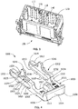
- FIG. 1 shows a perspective view of an electrical connector or plug 10 mated with a mating connector or header 100 which together form a connector assembly 50.
- the electrical connector 10 and mating connector 100 are shown as a representations.
- the connectors 10 and 100 will have many other features, such as contacts and contact latches, which are not shown in the figures.
- the electrical connector 10 has a housing body 12 with contact receiving passages 14 for receiving contacts therein, not shown.
- the electrical connector 10 has a forward mating end 16 and a rearward end 18.
- Conductors or wires 15, which are in electrical engagement with the contacts (not shown) are inserted in the passages 14 and extend from the rearward end 18.
- a first or top surface 19 and an oppositely facing second or bottom surface 21 extend between the mating end 16 and the rearward end 18.
- a latch or latch arm 22 having an engagement surface 23 and a latching opening 24 extends from the top surface 19.
- the latch 22 is connected to the top surface 19 proximate the forward mating end 16 and extends toward the rearward end 18.
- the latch 22 is used to latch and secure the mating connector 100 to the connector 10, as will be more fully described below.
- a connector position assurance (CPA) receiving opening 30 extending between the latch arm 22 and the housing body 12 .
- An upper knob or connector position assurance engagement projection 32 extends into the connector position assurance receiving opening 30 from a lower surface 33 of the housing body 12.
- a lower knob or connector position assurance engagement projection 34 extends into the connector position assurance receiving opening 30 from the top surface 19 of the housing body 12.
- Channels 40 FIG. 2 ) are provided proximate the latch arm 22 and respective support walls (not shown) which extend from the top surface 19. The channels 40 cooperate with the connector position assurance receiving opening 30 to house a portion of the connector position assurance member 1000 therein, as will be more fully discussed.
- the mating connector 100 has a complimentary latching protrusion 110 which is positioned to engage the latch arm 22 as the connector 10 and the mating connector are moved from an unmated position to a mated position.
- the latching protrusion 110 extends from a surface 122 of a shroud 120 of the mating connector 100.
- the latching protrusion 110 cooperates with and is positioned in the latching opening 24 to secure the mating connector 100 with the electrical connector 10.
- the connector 10 is received within the shroud 120 of the mating connector 100.
- Electrical contacts 130 ( FIG. 11 ) of the mating connector 100 mate with electrical contacts (not shown) in the electrical connector 10.
- Connector position assurance engagement ribs or projections 140 are provided on either side of the latching protrusion 110.
- the engagement projections or ribs 140 are spaced from the latching protrusion 110 and extend from the surface 122 of the shroud 120 of the mating connector 100. In the embodiment shown, the latching protrusion 110 extends a further distance from the surface 122 than the engagement projections 140.
- a connector position assurance device 1000 is positioned proximate to and is movable relative to the latch arm 22 of the connector 10.
- the connector position assurance device is maintained in the connector position assurance receiving opening 30 and is movable between a first position or open position, as shown in FIG. 5 , and a second or fully inserted position, as shown in FIG. 13 .
- the connector position assurance device 1000 is generally U-shaped having a base portion 1003 and two parallel beams 1002.
- the base portion 1003 is generally a rectangular plate having a top surface 1005, a bottom surface 1006, a base front end 1007 and a base back end 1008.
- the beams 1002 extend from the front end 1007 in a direction away from the back end 1008.
- the base portion 1003 includes a press bar 1004 extending along the back end 1008 for manually engaging or activating the connector position assurance device 1000, as will be more fully described.
- the press bar 1004 extends across the entire width of the back end 1008.
- a latch engagement protrusion 1010 extends from the top surface 1005 of the base portion 1003. As will be described further below, the latch engagement protrusion 1010 interacts with the latch 22.
- the beams 1002 are generally rectangular in shape. Each beam 1002 has a top side 1012, a bottom side 1013, a beam front end 1014 and a beam back end 1015. The back end 1015 is attached to or is integral with the front end 1007 of the base portion 1003.
- a mating connector engagement protrusion 1016 extends from the top side 1012 of each beam 1002, in a direction away from the bottom side 1013.
- each protrusion 1016 extends from a resiliently deformable top or first leg 1032 of the beam 1002.
- the protrusion 1016 is positioned generally or approximately midway between the front end 1014 and the back end 1015 of the beam 1002.
- Each beam 1002 has an opening 1030 which extends through a portion of the beam 1002 to form the top leg 1032 and a bottom leg 1034.
- First and second notches 1017, 1018 are provided along the bottom side 1013 of the beams 1002.
- the first and second notches 1017 and 1018 have sloped or angled side walls 1019.
- the slope of the angle walls 1019 may be adjusted to increase or decrease the force required to move or seat the connector position assurance device 1000.
- First and second notches 1020, 1021 are provided along the top side 1012 of the beams 1002.
- the first and second notches 1020, 1021 are provide proximate the protrusion 1016.
- the second notches 1021 have sloped or angled side walls 1022.
- the slope of the angle walls 1022 may be adjusted to increase or decrease the force required to move or seat the connector position assurance device 1000.
- the first notches 1020 have side walls 1023 which are essentially perpendicular to the bottom walls 1024 of the notches 1020.
- the side walls 1023 act as a stop surface to prevent the connector position assurance device 1000 from being removed from the connector position assurance receiving opening 30.
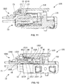
- FIGS. 5 through 14 The progression or method of inserting the plug or connector 10 into the header or mating connector 100 is shown.
- FIGS. 5 and 6 the connector 10 and the mating connector 100 are shown initially inserted in which the plug connector 10 is loosely positioned in the header connector 100. In this position, the latching protrusion 110 has not engaged the latch 22. As shown, the connector position assurance device 100 is maintained in the pre-mated, open or first position by the cooperation of the first notches 1017, 1020 with the respective projections 34, 32. In this position, the latch 22 is in a normal or undeflected position.
- the engagement surface 23 of the latch 22 engages the latching protrusion 110 of the mating connector 100, causing the engagement surface 23 and the latch 22 to be resiliently deformed activated or deflected away from the top surface 19 of the connector 10 toward the bottom surface 21 of the connector 10.
- the protrusions 1016 provided on the beams 1002 of the connector position assurance device 1000 are moved proximate to, adjacent to, or in initial engagement with the connector position assurance engagement projections 140.
- the protrusions 1016 provided on the beams 1002 of the connector position assurance device 1000 are moved along the surface of the connector position assurance engagement projections 140, forcing the protrusions 1016 to move toward the bottom sides 1013 of the beams 1002.
- the top legs 1032 are elastically deformed into the openings 1030, thereby allowing the first notches 1020 of the top sides 1012 to be moved away from projections 32.
- the connector position assurance device 1000 is maintained in position relative to the connector position assurance receiving opening 30 by the first notches 1017 with the projections 34.
- the connector 10 is fully inserted into the shroud 120 of the mating connector 100.
- the engagement surface 23 will be moved beyond the latching protrusion 110, allowing the latch 22 to resile to its normal, undeflected position.
- the latching protrusion 110 is inserted through the opening 24 of the latch 22, thereby latching the latch 22 on the latching protrusion 110 to secure the connector 10 to the mating connector 100.
- the connector position assurance device 1000 can be moved from the initial position to the locked position, as shown in FIG. 13 and 14 .
- a force or pressure is applied to the press bar 1004 in the direction of insertion.
- the projections 34 slide over the angled side walls 1019, allowing the projections 34 to be moved out of the first notches 1017.
- the connector position assurance device 1000 is moved in the receiving opening 30 toward the mating end 16.
- the connector position assurance device 1000 is returned to the initial position.
- a force applied in the press bar 1004 in the opposite direction of insertion allows the projections 34, 32 to slide over the angled side walls 1019, 1022, allowing the projections 34, 32 to be moved out of the second notches 1018, 1021.
- latch engagement protrusion 1010 is moved away from the latch 22, allowing the latch to be depressed, which in turn allows the connector 10 is to be unmated from the mating connector 110.
- the insertion of the connector position assurance device 1000 from the initial position to the locked position is prevented if the connector 10 is not mated to the mating connector 100, as shown in FIGS. 5 and 6 .
- the walls 1023 of the first notches 1020 are configured to prevent the removal of the projection 32 from the first notches 1020 unless the top legs 1032 are elastically deformed into the openings 1030, as previously described. As the top legs 1032 are only deformed by the cooperation of the protrusions 1016 with the engagement projections 140, if no engagement projections 140 are present, the connector position assurance device 1000 cannot be moved to the closed position.
- the connector position assurance device 1000 cannot be moved to the closed or locked position if the connector 10 is not properly or fully mated to the mating connector 100.
- the latch 22 will continue to be deflected from its normal, undeflected position. In this position, the engagement surface 23 of the latch 22 may engage the front end and/or the front surface 1011 of the engagement protrusion 1010, thereby preventing or blocking the continued insertion of the connector position assurance device 1000 toward the seated or closed position.
- the connector position assurance device cannot be moved to the locked position, an indication is provided that the connector 10 is not properly inserted within the mating connector 100 and this must be corrected.
Landscapes
- Details Of Connecting Devices For Male And Female Coupling (AREA)
Applications Claiming Priority (3)
| Application Number | Priority Date | Filing Date | Title |
|---|---|---|---|
| US201461954761P | 2014-03-18 | 2014-03-18 | |
| US14/656,846 US9478906B2 (en) | 2014-03-18 | 2015-03-13 | Connector mating assurance |
| PCT/US2015/020642 WO2015142686A1 (en) | 2014-03-18 | 2015-03-16 | Connector mating assurance |
Publications (2)
| Publication Number | Publication Date |
|---|---|
| EP3120422A1 EP3120422A1 (en) | 2017-01-25 |
| EP3120422B1 true EP3120422B1 (en) | 2019-07-17 |
Family
ID=54142974
Family Applications (1)
| Application Number | Title | Priority Date | Filing Date |
|---|---|---|---|
| EP15713609.4A Active EP3120422B1 (en) | 2014-03-18 | 2015-03-16 | Electrical connector assembly |
Country Status (7)
| Country | Link |
|---|---|
| US (1) | US9478906B2 (ko) |
| EP (1) | EP3120422B1 (ko) |
| JP (1) | JP6419210B2 (ko) |
| KR (1) | KR101834111B1 (ko) |
| CN (1) | CN106134012B (ko) |
| MX (1) | MX2016012069A (ko) |
| WO (1) | WO2015142686A1 (ko) |
Cited By (2)
| Publication number | Priority date | Publication date | Assignee | Title |
|---|---|---|---|---|
| DE102022101311A1 (de) | 2022-01-20 | 2023-07-20 | Md Elektronik Gmbh | Steckverbinder |
| EP4002604A4 (en) * | 2019-07-18 | 2023-08-02 | Tyco Electronics Japan G.K. | INTERCONNECTS |
Families Citing this family (23)
| Publication number | Priority date | Publication date | Assignee | Title |
|---|---|---|---|---|
| US9318836B2 (en) * | 2014-02-06 | 2016-04-19 | Dai-Ichi Seiko Co., Ltd. | Electric connector |
| JP6213591B2 (ja) * | 2016-02-25 | 2017-10-18 | 第一精工株式会社 | コネクタ |
| JP6213592B2 (ja) * | 2016-02-25 | 2017-10-18 | 第一精工株式会社 | コネクタ |
| FR3049118A1 (fr) * | 2016-03-15 | 2017-09-22 | Tyco Electronics France Sas | Dispositif d'assurance de position de connecteur, boitier de connecteur et systeme de connecteur electrique |
| US10038278B2 (en) | 2016-03-17 | 2018-07-31 | Te Connectivity Corporation | Electrical connector having a connector position assurance element |
| JP6569131B2 (ja) * | 2016-04-26 | 2019-09-04 | 株式会社オートネットワーク技術研究所 | 嵌合検知機能を有する電気接続装置 |
| US9653846B1 (en) * | 2016-06-09 | 2017-05-16 | Delphi Technologies, Inc. | Connector assembly with positional assurance |
| JP6417370B2 (ja) * | 2016-07-29 | 2018-11-07 | 矢崎総業株式会社 | コネクタ |
| US10454209B2 (en) | 2017-05-01 | 2019-10-22 | J.S.T. Corporation | Connector position assurance device, a connector apparatus having male and female connector assemblies with connector position assurance device, a male connector assembly, a female connector assembly, and a method for assembling the connector apparatus |
| US10855025B2 (en) | 2017-05-01 | 2020-12-01 | J.S.T. Corporation | Connector position assurance device, connector system and method for operating the connector system |
| JP2019008970A (ja) * | 2017-06-23 | 2019-01-17 | 住友電装株式会社 | コネクタ |
| US10038269B1 (en) * | 2017-06-29 | 2018-07-31 | Cisco Technology, Inc. | Self-locking electrical cable retainer |
| CN207320479U (zh) * | 2017-10-17 | 2018-05-04 | 安费诺精密连接器(深圳)有限公司 | 一种高压连接器 |
| JP6981844B2 (ja) * | 2017-10-23 | 2021-12-17 | タイコエレクトロニクスジャパン合同会社 | コネクタおよびコネクタ組立体 |
| US10468805B2 (en) * | 2018-03-23 | 2019-11-05 | Te Connectivity Corporation | Connector position assurance member |
| US10587076B2 (en) * | 2018-03-23 | 2020-03-10 | Te Connectivity Corporation | Connector position assurance member |
| US10135172B1 (en) * | 2018-03-23 | 2018-11-20 | Te Connectivity Corporation | Connector position assurance member |
| US10505314B1 (en) * | 2018-11-02 | 2019-12-10 | Te Connectivity Corporation | Electrical connector with a connector position assurance member for a shrouded latch |
| US11251560B2 (en) * | 2019-03-11 | 2022-02-15 | TE Connectivity Services Gmbh | Terminal position assurance member with multiple latches |
| CN113557641B (zh) * | 2019-03-13 | 2024-03-15 | 泰连服务有限公司 | 连接器位置保证构件 |
| JP2021005519A (ja) * | 2019-06-27 | 2021-01-14 | 住友電装株式会社 | コネクタ |
| CN114709664A (zh) * | 2021-12-27 | 2022-07-05 | 安波福中央电气(上海)有限公司 | 稳定装置、连接器组件以及连接器组装体 |
| JP2024072416A (ja) * | 2022-11-16 | 2024-05-28 | 日本航空電子工業株式会社 | コネクタ及びコネクタ組立体 |
Citations (1)
| Publication number | Priority date | Publication date | Assignee | Title |
|---|---|---|---|---|
| US20020052135A1 (en) * | 2000-10-31 | 2002-05-02 | Sumitomo Wiring Systems, Ltd. | Connector |
Family Cites Families (16)
| Publication number | Priority date | Publication date | Assignee | Title |
|---|---|---|---|---|
| JPH0743971Y2 (ja) | 1988-10-17 | 1995-10-09 | マツダ株式会社 | コネクタ装置 |
| US5507666A (en) | 1993-12-28 | 1996-04-16 | Yazaki Corporation | Lock securing mechanism for connectors |
| JP2907258B2 (ja) * | 1993-12-28 | 1999-06-21 | 矢崎総業株式会社 | コネクタのロック保障部材 |
| PT746057E (pt) * | 1995-05-31 | 2000-04-28 | Molex Inc | Sistema para assegurar a posicao dos terminais num conector electrico |
| US6261115B1 (en) * | 1999-06-11 | 2001-07-17 | Tyco Electronics Logistics Ag | Connector module |
| CA2277682C (en) | 1998-07-30 | 2007-12-04 | Osram Sylvania Inc. | Connector module |
| US6780045B2 (en) * | 2002-03-06 | 2004-08-24 | Tyco Electronics Corporation | Connector position assurance device |
| JP3997858B2 (ja) * | 2002-07-24 | 2007-10-24 | 住友電装株式会社 | 嵌合検知コネクタ |
| SG143088A1 (en) * | 2006-11-22 | 2008-06-27 | Mea Technologies Pte Ltd | Electrical connector |
| US7399195B2 (en) * | 2006-12-06 | 2008-07-15 | J.S.T. Corporation | Connector position assurance device and connector assembly incorporating the same |
| CN101884143B (zh) * | 2007-10-12 | 2013-06-05 | 富加宜汽车控股公司 | 具有连接器定位装置的电连接器组件 |
| KR100988786B1 (ko) | 2008-03-31 | 2010-10-20 | 한국단자공업 주식회사 | 커넥터 어셈블리 |
| JP5562108B2 (ja) * | 2010-04-26 | 2014-07-30 | 日本端子株式会社 | ロック検知コネクタ |
| US8137142B1 (en) * | 2011-09-22 | 2012-03-20 | Yazaki North America, Inc. | Connector assembly |
| US8920187B2 (en) * | 2012-03-09 | 2014-12-30 | Sumitomo Wiring Systems, Ltd. | Connector and connector assembly |
| US8888521B2 (en) | 2012-06-13 | 2014-11-18 | J.S.T. Corporation | In-line sealed electrical connector apparatus having a connector apparatus position assurance device, and locking method thereof |
-
2015
- 2015-03-13 US US14/656,846 patent/US9478906B2/en active Active
- 2015-03-16 MX MX2016012069A patent/MX2016012069A/es active IP Right Grant
- 2015-03-16 WO PCT/US2015/020642 patent/WO2015142686A1/en active Application Filing
- 2015-03-16 EP EP15713609.4A patent/EP3120422B1/en active Active
- 2015-03-16 JP JP2016557213A patent/JP6419210B2/ja active Active
- 2015-03-16 KR KR1020167028469A patent/KR101834111B1/ko active IP Right Grant
- 2015-03-16 CN CN201580013882.8A patent/CN106134012B/zh active Active
Patent Citations (1)
| Publication number | Priority date | Publication date | Assignee | Title |
|---|---|---|---|---|
| US20020052135A1 (en) * | 2000-10-31 | 2002-05-02 | Sumitomo Wiring Systems, Ltd. | Connector |
Cited By (3)
| Publication number | Priority date | Publication date | Assignee | Title |
|---|---|---|---|---|
| EP4002604A4 (en) * | 2019-07-18 | 2023-08-02 | Tyco Electronics Japan G.K. | INTERCONNECTS |
| US11962106B2 (en) | 2019-07-18 | 2024-04-16 | Tyco Electronics Japan G.K. | Connector |
| DE102022101311A1 (de) | 2022-01-20 | 2023-07-20 | Md Elektronik Gmbh | Steckverbinder |
Also Published As
| Publication number | Publication date |
|---|---|
| KR20160135270A (ko) | 2016-11-25 |
| US9478906B2 (en) | 2016-10-25 |
| CN106134012B (zh) | 2019-04-09 |
| KR101834111B1 (ko) | 2018-03-02 |
| JP2017508257A (ja) | 2017-03-23 |
| CN106134012A (zh) | 2016-11-16 |
| WO2015142686A1 (en) | 2015-09-24 |
| MX2016012069A (es) | 2017-01-19 |
| EP3120422A1 (en) | 2017-01-25 |
| JP6419210B2 (ja) | 2018-11-07 |
| US20150270643A1 (en) | 2015-09-24 |
Similar Documents
| Publication | Publication Date | Title |
|---|---|---|
| EP3120422B1 (en) | Electrical connector assembly | |
| US10135172B1 (en) | Connector position assurance member | |
| KR200465368Y1 (ko) | 커넥터 위치 보장 장치를 갖는 전기 커넥터 조립체 | |
| US6241542B1 (en) | Connector with shorting terminal | |
| EP3769377B1 (en) | Connector position assurance member | |
| US20130252455A1 (en) | Connector assembly | |
| US10587076B2 (en) | Connector position assurance member | |
| US6685506B1 (en) | Connector and a method for connecting such connector with a mating connector | |
| CN111146651B (zh) | 具有用于带罩闩锁的连接器位置保证构件的电连接器 | |
| EP3734770B1 (en) | Electrical connector having position holder | |
| CN113557641B (zh) | 连接器位置保证构件 | |
| JP2020155222A (ja) | コネクタ | |
| JP7389407B2 (ja) | カードエッジコネクタ | |
| JP3951469B2 (ja) | コネクタ | |
| JP2009117269A (ja) | コネクタ |
Legal Events
| Date | Code | Title | Description |
|---|---|---|---|
| STAA | Information on the status of an ep patent application or granted ep patent |
Free format text: STATUS: THE INTERNATIONAL PUBLICATION HAS BEEN MADE |
|
| PUAI | Public reference made under article 153(3) epc to a published international application that has entered the european phase |
Free format text: ORIGINAL CODE: 0009012 |
|
| STAA | Information on the status of an ep patent application or granted ep patent |
Free format text: STATUS: REQUEST FOR EXAMINATION WAS MADE |
|
| 17P | Request for examination filed |
Effective date: 20161011 |
|
| AK | Designated contracting states |
Kind code of ref document: A1 Designated state(s): AL AT BE BG CH CY CZ DE DK EE ES FI FR GB GR HR HU IE IS IT LI LT LU LV MC MK MT NL NO PL PT RO RS SE SI SK SM TR |
|
| AX | Request for extension of the european patent |
Extension state: BA ME |
|
| RAP1 | Party data changed (applicant data changed or rights of an application transferred) |
Owner name: TE CONNECTIVITY CORPORATION |
|
| DAV | Request for validation of the european patent (deleted) | ||
| DAX | Request for extension of the european patent (deleted) | ||
| STAA | Information on the status of an ep patent application or granted ep patent |
Free format text: STATUS: EXAMINATION IS IN PROGRESS |
|
| 17Q | First examination report despatched |
Effective date: 20180302 |
|
| GRAP | Despatch of communication of intention to grant a patent |
Free format text: ORIGINAL CODE: EPIDOSNIGR1 |
|
| STAA | Information on the status of an ep patent application or granted ep patent |
Free format text: STATUS: GRANT OF PATENT IS INTENDED |
|
| INTG | Intention to grant announced |
Effective date: 20190123 |
|
| GRAS | Grant fee paid |
Free format text: ORIGINAL CODE: EPIDOSNIGR3 |
|
| GRAJ | Information related to disapproval of communication of intention to grant by the applicant or resumption of examination proceedings by the epo deleted |
Free format text: ORIGINAL CODE: EPIDOSDIGR1 |
|
| GRAL | Information related to payment of fee for publishing/printing deleted |
Free format text: ORIGINAL CODE: EPIDOSDIGR3 |
|
| STAA | Information on the status of an ep patent application or granted ep patent |
Free format text: STATUS: EXAMINATION IS IN PROGRESS |
|
| GRAR | Information related to intention to grant a patent recorded |
Free format text: ORIGINAL CODE: EPIDOSNIGR71 |
|
| STAA | Information on the status of an ep patent application or granted ep patent |
Free format text: STATUS: GRANT OF PATENT IS INTENDED |
|
| GRAA | (expected) grant |
Free format text: ORIGINAL CODE: 0009210 |
|
| STAA | Information on the status of an ep patent application or granted ep patent |
Free format text: STATUS: THE PATENT HAS BEEN GRANTED |
|
| INTC | Intention to grant announced (deleted) | ||
| AK | Designated contracting states |
Kind code of ref document: B1 Designated state(s): AL AT BE BG CH CY CZ DE DK EE ES FI FR GB GR HR HU IE IS IT LI LT LU LV MC MK MT NL NO PL PT RO RS SE SI SK SM TR |
|
| INTG | Intention to grant announced |
Effective date: 20190612 |
|
| REG | Reference to a national code |
Ref country code: GB Ref legal event code: FG4D |
|
| REG | Reference to a national code |
Ref country code: CH Ref legal event code: EP |
|
| REG | Reference to a national code |
Ref country code: IE Ref legal event code: FG4D |
|
| REG | Reference to a national code |
Ref country code: DE Ref legal event code: R096 Ref document number: 602015033885 Country of ref document: DE |
|
| REG | Reference to a national code |
Ref country code: AT Ref legal event code: REF Ref document number: 1156687 Country of ref document: AT Kind code of ref document: T Effective date: 20190815 |
|
| REG | Reference to a national code |
Ref country code: NL Ref legal event code: MP Effective date: 20190717 |
|
| REG | Reference to a national code |
Ref country code: LT Ref legal event code: MG4D |
|
| REG | Reference to a national code |
Ref country code: AT Ref legal event code: MK05 Ref document number: 1156687 Country of ref document: AT Kind code of ref document: T Effective date: 20190717 |
|
| PG25 | Lapsed in a contracting state [announced via postgrant information from national office to epo] |
Ref country code: NO Free format text: LAPSE BECAUSE OF FAILURE TO SUBMIT A TRANSLATION OF THE DESCRIPTION OR TO PAY THE FEE WITHIN THE PRESCRIBED TIME-LIMIT Effective date: 20191017 Ref country code: SE Free format text: LAPSE BECAUSE OF FAILURE TO SUBMIT A TRANSLATION OF THE DESCRIPTION OR TO PAY THE FEE WITHIN THE PRESCRIBED TIME-LIMIT Effective date: 20190717 Ref country code: PT Free format text: LAPSE BECAUSE OF FAILURE TO SUBMIT A TRANSLATION OF THE DESCRIPTION OR TO PAY THE FEE WITHIN THE PRESCRIBED TIME-LIMIT Effective date: 20191118 Ref country code: BG Free format text: LAPSE BECAUSE OF FAILURE TO SUBMIT A TRANSLATION OF THE DESCRIPTION OR TO PAY THE FEE WITHIN THE PRESCRIBED TIME-LIMIT Effective date: 20191017 Ref country code: NL Free format text: LAPSE BECAUSE OF FAILURE TO SUBMIT A TRANSLATION OF THE DESCRIPTION OR TO PAY THE FEE WITHIN THE PRESCRIBED TIME-LIMIT Effective date: 20190717 Ref country code: LT Free format text: LAPSE BECAUSE OF FAILURE TO SUBMIT A TRANSLATION OF THE DESCRIPTION OR TO PAY THE FEE WITHIN THE PRESCRIBED TIME-LIMIT Effective date: 20190717 Ref country code: HR Free format text: LAPSE BECAUSE OF FAILURE TO SUBMIT A TRANSLATION OF THE DESCRIPTION OR TO PAY THE FEE WITHIN THE PRESCRIBED TIME-LIMIT Effective date: 20190717 Ref country code: FI Free format text: LAPSE BECAUSE OF FAILURE TO SUBMIT A TRANSLATION OF THE DESCRIPTION OR TO PAY THE FEE WITHIN THE PRESCRIBED TIME-LIMIT Effective date: 20190717 Ref country code: AT Free format text: LAPSE BECAUSE OF FAILURE TO SUBMIT A TRANSLATION OF THE DESCRIPTION OR TO PAY THE FEE WITHIN THE PRESCRIBED TIME-LIMIT Effective date: 20190717 |
|
| PG25 | Lapsed in a contracting state [announced via postgrant information from national office to epo] |
Ref country code: GR Free format text: LAPSE BECAUSE OF FAILURE TO SUBMIT A TRANSLATION OF THE DESCRIPTION OR TO PAY THE FEE WITHIN THE PRESCRIBED TIME-LIMIT Effective date: 20191018 Ref country code: AL Free format text: LAPSE BECAUSE OF FAILURE TO SUBMIT A TRANSLATION OF THE DESCRIPTION OR TO PAY THE FEE WITHIN THE PRESCRIBED TIME-LIMIT Effective date: 20190717 Ref country code: LV Free format text: LAPSE BECAUSE OF FAILURE TO SUBMIT A TRANSLATION OF THE DESCRIPTION OR TO PAY THE FEE WITHIN THE PRESCRIBED TIME-LIMIT Effective date: 20190717 Ref country code: ES Free format text: LAPSE BECAUSE OF FAILURE TO SUBMIT A TRANSLATION OF THE DESCRIPTION OR TO PAY THE FEE WITHIN THE PRESCRIBED TIME-LIMIT Effective date: 20190717 Ref country code: IS Free format text: LAPSE BECAUSE OF FAILURE TO SUBMIT A TRANSLATION OF THE DESCRIPTION OR TO PAY THE FEE WITHIN THE PRESCRIBED TIME-LIMIT Effective date: 20191117 Ref country code: RS Free format text: LAPSE BECAUSE OF FAILURE TO SUBMIT A TRANSLATION OF THE DESCRIPTION OR TO PAY THE FEE WITHIN THE PRESCRIBED TIME-LIMIT Effective date: 20190717 |
|
| PG25 | Lapsed in a contracting state [announced via postgrant information from national office to epo] |
Ref country code: TR Free format text: LAPSE BECAUSE OF FAILURE TO SUBMIT A TRANSLATION OF THE DESCRIPTION OR TO PAY THE FEE WITHIN THE PRESCRIBED TIME-LIMIT Effective date: 20190717 |
|
| PG25 | Lapsed in a contracting state [announced via postgrant information from national office to epo] |
Ref country code: IT Free format text: LAPSE BECAUSE OF FAILURE TO SUBMIT A TRANSLATION OF THE DESCRIPTION OR TO PAY THE FEE WITHIN THE PRESCRIBED TIME-LIMIT Effective date: 20190717 Ref country code: RO Free format text: LAPSE BECAUSE OF FAILURE TO SUBMIT A TRANSLATION OF THE DESCRIPTION OR TO PAY THE FEE WITHIN THE PRESCRIBED TIME-LIMIT Effective date: 20190717 Ref country code: PL Free format text: LAPSE BECAUSE OF FAILURE TO SUBMIT A TRANSLATION OF THE DESCRIPTION OR TO PAY THE FEE WITHIN THE PRESCRIBED TIME-LIMIT Effective date: 20190717 Ref country code: EE Free format text: LAPSE BECAUSE OF FAILURE TO SUBMIT A TRANSLATION OF THE DESCRIPTION OR TO PAY THE FEE WITHIN THE PRESCRIBED TIME-LIMIT Effective date: 20190717 Ref country code: DK Free format text: LAPSE BECAUSE OF FAILURE TO SUBMIT A TRANSLATION OF THE DESCRIPTION OR TO PAY THE FEE WITHIN THE PRESCRIBED TIME-LIMIT Effective date: 20190717 |
|
| PG25 | Lapsed in a contracting state [announced via postgrant information from national office to epo] |
Ref country code: SM Free format text: LAPSE BECAUSE OF FAILURE TO SUBMIT A TRANSLATION OF THE DESCRIPTION OR TO PAY THE FEE WITHIN THE PRESCRIBED TIME-LIMIT Effective date: 20190717 Ref country code: SK Free format text: LAPSE BECAUSE OF FAILURE TO SUBMIT A TRANSLATION OF THE DESCRIPTION OR TO PAY THE FEE WITHIN THE PRESCRIBED TIME-LIMIT Effective date: 20190717 Ref country code: IS Free format text: LAPSE BECAUSE OF FAILURE TO SUBMIT A TRANSLATION OF THE DESCRIPTION OR TO PAY THE FEE WITHIN THE PRESCRIBED TIME-LIMIT Effective date: 20200224 Ref country code: CZ Free format text: LAPSE BECAUSE OF FAILURE TO SUBMIT A TRANSLATION OF THE DESCRIPTION OR TO PAY THE FEE WITHIN THE PRESCRIBED TIME-LIMIT Effective date: 20190717 |
|
| REG | Reference to a national code |
Ref country code: DE Ref legal event code: R097 Ref document number: 602015033885 Country of ref document: DE |
|
| PLBE | No opposition filed within time limit |
Free format text: ORIGINAL CODE: 0009261 |
|
| STAA | Information on the status of an ep patent application or granted ep patent |
Free format text: STATUS: NO OPPOSITION FILED WITHIN TIME LIMIT |
|
| PG2D | Information on lapse in contracting state deleted |
Ref country code: IS |
|
| 26N | No opposition filed |
Effective date: 20200603 |
|
| PG25 | Lapsed in a contracting state [announced via postgrant information from national office to epo] |
Ref country code: SI Free format text: LAPSE BECAUSE OF FAILURE TO SUBMIT A TRANSLATION OF THE DESCRIPTION OR TO PAY THE FEE WITHIN THE PRESCRIBED TIME-LIMIT Effective date: 20190717 |
|
| PG25 | Lapsed in a contracting state [announced via postgrant information from national office to epo] |
Ref country code: MC Free format text: LAPSE BECAUSE OF FAILURE TO SUBMIT A TRANSLATION OF THE DESCRIPTION OR TO PAY THE FEE WITHIN THE PRESCRIBED TIME-LIMIT Effective date: 20190717 |
|
| REG | Reference to a national code |
Ref country code: CH Ref legal event code: PL |
|
| REG | Reference to a national code |
Ref country code: BE Ref legal event code: MM Effective date: 20200331 |
|
| PG25 | Lapsed in a contracting state [announced via postgrant information from national office to epo] |
Ref country code: LU Free format text: LAPSE BECAUSE OF NON-PAYMENT OF DUE FEES Effective date: 20200316 |
|
| PG25 | Lapsed in a contracting state [announced via postgrant information from national office to epo] |
Ref country code: LI Free format text: LAPSE BECAUSE OF NON-PAYMENT OF DUE FEES Effective date: 20200331 Ref country code: FR Free format text: LAPSE BECAUSE OF NON-PAYMENT OF DUE FEES Effective date: 20200331 Ref country code: CH Free format text: LAPSE BECAUSE OF NON-PAYMENT OF DUE FEES Effective date: 20200331 Ref country code: IE Free format text: LAPSE BECAUSE OF NON-PAYMENT OF DUE FEES Effective date: 20200316 |
|
| PG25 | Lapsed in a contracting state [announced via postgrant information from national office to epo] |
Ref country code: BE Free format text: LAPSE BECAUSE OF NON-PAYMENT OF DUE FEES Effective date: 20200331 |
|
| GBPC | Gb: european patent ceased through non-payment of renewal fee |
Effective date: 20200316 |
|
| PG25 | Lapsed in a contracting state [announced via postgrant information from national office to epo] |
Ref country code: GB Free format text: LAPSE BECAUSE OF NON-PAYMENT OF DUE FEES Effective date: 20200316 |
|
| PG25 | Lapsed in a contracting state [announced via postgrant information from national office to epo] |
Ref country code: MT Free format text: LAPSE BECAUSE OF FAILURE TO SUBMIT A TRANSLATION OF THE DESCRIPTION OR TO PAY THE FEE WITHIN THE PRESCRIBED TIME-LIMIT Effective date: 20190717 Ref country code: CY Free format text: LAPSE BECAUSE OF FAILURE TO SUBMIT A TRANSLATION OF THE DESCRIPTION OR TO PAY THE FEE WITHIN THE PRESCRIBED TIME-LIMIT Effective date: 20190717 |
|
| PG25 | Lapsed in a contracting state [announced via postgrant information from national office to epo] |
Ref country code: MK Free format text: LAPSE BECAUSE OF FAILURE TO SUBMIT A TRANSLATION OF THE DESCRIPTION OR TO PAY THE FEE WITHIN THE PRESCRIBED TIME-LIMIT Effective date: 20190717 |
|
| PGFP | Annual fee paid to national office [announced via postgrant information from national office to epo] |
Ref country code: DE Payment date: 20231229 Year of fee payment: 10 |