EP3119944B1 - Hydraulic assembly for controlling a liquid - Google Patents
Hydraulic assembly for controlling a liquid Download PDFInfo
- Publication number
- EP3119944B1 EP3119944B1 EP15718606.5A EP15718606A EP3119944B1 EP 3119944 B1 EP3119944 B1 EP 3119944B1 EP 15718606 A EP15718606 A EP 15718606A EP 3119944 B1 EP3119944 B1 EP 3119944B1
- Authority
- EP
- European Patent Office
- Prior art keywords
- connector
- hydraulic
- base
- base element
- hydraulic assembly
- Prior art date
- Legal status (The legal status is an assumption and is not a legal conclusion. Google has not performed a legal analysis and makes no representation as to the accuracy of the status listed.)
- Active
Links
Images


Classifications
-
- E—FIXED CONSTRUCTIONS
- E03—WATER SUPPLY; SEWERAGE
- E03B—INSTALLATIONS OR METHODS FOR OBTAINING, COLLECTING, OR DISTRIBUTING WATER
- E03B7/00—Water main or service pipe systems
- E03B7/07—Arrangement of devices, e.g. filters, flow controls, measuring devices, siphons or valves, in the pipe systems
- E03B7/078—Combined units with different devices; Arrangement of different devices with respect to each other
-
- E—FIXED CONSTRUCTIONS
- E03—WATER SUPPLY; SEWERAGE
- E03B—INSTALLATIONS OR METHODS FOR OBTAINING, COLLECTING, OR DISTRIBUTING WATER
- E03B7/00—Water main or service pipe systems
- E03B7/07—Arrangement of devices, e.g. filters, flow controls, measuring devices, siphons or valves, in the pipe systems
- E03B7/072—Arrangement of flowmeters
-
- E—FIXED CONSTRUCTIONS
- E03—WATER SUPPLY; SEWERAGE
- E03B—INSTALLATIONS OR METHODS FOR OBTAINING, COLLECTING, OR DISTRIBUTING WATER
- E03B7/00—Water main or service pipe systems
- E03B7/07—Arrangement of devices, e.g. filters, flow controls, measuring devices, siphons or valves, in the pipe systems
- E03B7/074—Arrangement of water treatment devices
-
- E—FIXED CONSTRUCTIONS
- E03—WATER SUPPLY; SEWERAGE
- E03B—INSTALLATIONS OR METHODS FOR OBTAINING, COLLECTING, OR DISTRIBUTING WATER
- E03B7/00—Water main or service pipe systems
- E03B7/07—Arrangement of devices, e.g. filters, flow controls, measuring devices, siphons or valves, in the pipe systems
- E03B7/075—Arrangement of devices for control of pressure or flow rate
-
- F—MECHANICAL ENGINEERING; LIGHTING; HEATING; WEAPONS; BLASTING
- F16—ENGINEERING ELEMENTS AND UNITS; GENERAL MEASURES FOR PRODUCING AND MAINTAINING EFFECTIVE FUNCTIONING OF MACHINES OR INSTALLATIONS; THERMAL INSULATION IN GENERAL
- F16K—VALVES; TAPS; COCKS; ACTUATING-FLOATS; DEVICES FOR VENTING OR AERATING
- F16K27/00—Construction of housing; Use of materials therefor
- F16K27/003—Housing formed from a plurality of the same valve elements
-
- Y—GENERAL TAGGING OF NEW TECHNOLOGICAL DEVELOPMENTS; GENERAL TAGGING OF CROSS-SECTIONAL TECHNOLOGIES SPANNING OVER SEVERAL SECTIONS OF THE IPC; TECHNICAL SUBJECTS COVERED BY FORMER USPC CROSS-REFERENCE ART COLLECTIONS [XRACs] AND DIGESTS
- Y10—TECHNICAL SUBJECTS COVERED BY FORMER USPC
- Y10T—TECHNICAL SUBJECTS COVERED BY FORMER US CLASSIFICATION
- Y10T137/00—Fluid handling
- Y10T137/8593—Systems
- Y10T137/877—With flow control means for branched passages
- Y10T137/87885—Sectional block structure
Definitions
- the present invention relates to a hydraulic assembly for controlling a liquid.
- the present invention relates to a hydraulic assembly for controlling a liquid which can be used, for example, in irrigation systems, inside household appliances, in the hydraulic circuits of whirlpool baths, in taps, in automatic beverage vending machines and in many other applications in which the selective control of a liquid is required.
- Hydraulic assemblies defined by a plurality of elements, such as, for example, filters, solenoid valves, water metering devices, pressure regulators etc., which are coupled to one another so as to form a composition adapted to control a flow of liquid, are known. Examples of such assemblies are disclosed in documents DE29806644 , US5855224 and US5089131 .
- the present invention relates to a hydraulic assembly for controlling a liquid according to claim 1.
- each hydraulic module comprises two connectors which can be connected to one another, all the base elements may be coupled directly to one another without needing to engage interconnection devices. Therefore, the coupling of the base elements of the hydraulic modules is simplified and the composition flexibility of a hydraulic circuit is optimized.
- each base module allows a rapid customization of each hydraulic module and, consequently, a rapid customization of the entire composition of the hydraulic assembly.
- the hydraulic module assumes a specific function according to the type of coupled interactive element.
- the first or third connector is female and the second or fourth connector is male. Therefore, the coupling between the first or third and the second or fourth connector is simple, intuitive and rapid.
- the interactive element is configured to operate on the liquid running in the base element.
- the hydraulic module controls the liquid by interrupting the flow thereof, adjusting the flow rate, adjusting the pressure, filtering it, etc.
- the interactive element is configured to modify its state on the basis of the liquid running in the base element. Therefore, the hydraulic module comprising such an interactive element is configured to control the liquid by modifying its state, e.g. by measuring the liquid flow rate, measuring the pressure of the liquid, etc.
- the interactive element is selected from the group comprising a filter, a solenoid valve, a valve, a pressure regulator, a water metering device, a pressure detector, a check valve etc.
- the hydraulic modules may be customized by coupling each base element according to a respective interactive element belonging to the assembly described above.
- the interactive element is coupled to the base body of the base element. Therefore, it will be sufficient to couple the respective interactive element to the base body only in order to commit a given function to a hydraulic module. Therefore, the customization operations of the various hydraulic modules are simplified. Furthermore, the maintenance and replacement operations of the interactive elements are simplified and rapid.
- the base bodies of the plurality of first hydraulic modules are mutually identical. Therefore, the assembly and customization operations of the composition are simplified. Furthermore, the production costs of the hydraulic modules are reduced there being an identical portion which can be produced on large scale in each module.
- the first connector and the second connector and/or the third connector and the fourth connector are configured so as to define a quick coupling. Therefore, the time necessary for coupling the hydraulic modules to one another is reduced and no tools are needed.
- the first connector and the second connector and/or the third connector and the fourth connector are configured so as to define a bayonet type coupling. Therefore, the coupling between the various modules is obtained rapidly and simply by means of an axial movement to allow the introduction of the male connector in the female connector and a rotational movement to couple the male connector to the female connector.
- the first connector and the second connector and/or the third connector and the fourth connector are aligned along an axis. Therefore, the base element allows the passage of the liquid without diverting it.
- the first connector and the second connector and/or the third connector and the fourth connector are arranged transversely with respect to one another. Therefore, the base element diverts the liquid.
- the second base element comprises a fifth connector which can be coupled either to the third connector or to the fourth connector or the first connector. Therefore, the second base element defines three running ways for the liquid.
- the fifth connector can be coupled either to the third or to the fourth or to the first connector
- the base elements of the plurality of hydraulic modules can be coupled directly to one another without needing to engage specifically made interconnection devices.
- the second base elements having three connectors may therefore be connected directly to the base elements having only two connectors, and vice versa.
- the hydraulic assembly comprises at least one adapter element configured to couple the first connector and/or the second connector and/or the third connector and/or the fourth connector to a hydraulic element external to the hydraulic assembly. Therefore, the hydraulic circuit may be installed in a hydraulic circuit having any type of connections. Indeed, the adapter element can connect at least one of the free terminal connectors of the hydraulic assembly.
- the hydraulic assembly comprises at least one T-shaped or at least one L-shaped joint element.
- the freedom of composition of the hydraulic assembly is thus improved.
- reference numeral 1 indicates a hydraulic assembly for controlling a liquid.
- the hydraulic assembly 1 comprises a plurality of hydraulic modules 2 connected to one another.
- the hydraulic assembly 1 comprises three hydraulic modules 2 coupled to one another in series, so that the liquid flows in sequence in each hydraulic module 2 of the hydraulic assembly 1.
- composition of the hydraulic assembly 1 may vary according to control needs, as will be seen below with regards to an embodiment of the hydraulic assembly according to the present invention shown in figure 3 .
- Each hydraulic module 2 is provided with a base element 3, in which the liquid flows in use and an interactive element 4 coupled to the base element 3 and configured to interact with the liquid running in the base element 3.
- each base element 3 is coupled to the interactive element 4 in three points (of which only two are shown in figure 1 ) by means of fastening screws 5. It is understood that the interactive module 4 and the respective base element 3 can be coupled in any possible manner, e.g. by interference, by snapping, by threading etc.
- Figure 2 shows a first embodiment of a hydraulic module 2, engaged in the hydraulic assembly 1 in figure 1 .
- the base element 3 of the hydraulic module 2 comprises a base body 7, a first connector 8 and a second connector 9.
- a base body 7 is coupled to the first connector 8, to the second connector 9 and to the respective interactive element 4.
- the base body 7 is a hollow body provided with a first opening 10 coupled to the first connector 8, with a second opening 11 coupled to the second connector 9 and with a third opening 12 (not clearly shown in figure 2 ) coupled to the interactive element 4.
- the base body 7 thus defines a cavity having three openings (not shown in the accompanying figures) in which the liquid runs in use.
- the first connector 8, the second connector 9 and the interactive element 4 are in fluid communication with the cavity defined by the base body 7.
- the cavity is shaped so as to convey the input liquid through either the first connector 8 or the second connector 9 towards the interactive element 4 so as to promote the interaction between the liquid and the interactive element 4.
- the first connector 8 and the second connector 9 are made in one piece with the base body 7, while the interactive element 4 is coupled to the base body 7 in three points (only two of which are shown in figure 1 ) by means of the fastening screws 5.
- the liquid enters through the first connector 8, interacts with the interactive element 4 and exits through the second connector 9 (as shown by the arrows in figure 1 ) in use.
- liquid may run in the opposite direction, according to the configuration of the hydraulic assembly 1 in which the modular element 2 is comprised.
- the first connector 8 and the second connector 9 can be mutually coupled.
- the first connector 8 is female while the second connector 9 is male.
- each base element 3 can be coupled directly to a further base element 3 without using interconnection elements and so as to define a modular structure of the hydraulic assembly 1 ( figure 1 ).
- first connector 8 and the second connector 9 are aligned along an axis A.
- first connector 8 and the second connector 9 are arranged transversely with respect to one another.
- first connector 8 and the second connector 9 are configured so as to define a quick coupling.
- the expression "quick coupling” hereinafter means that the first connector 8 and the second connector 9 are configured so as to be coupled by means of quick and/or short movements and preferably without using tools/accessories.
- first connector 8 and the second connector 9 are shaped so as to define a coupling of the bayonet type.
- first connector 8 and the second connector 9 are made so as to define a snap coupling.
- the interactive element 4 may be chosen from two types:
- the interactive element 4 of each hydraulic module 2 is selected from the group comprising a filter, a solenoid valve, a valve, a pressure regulator, a water metering device, flow rate regulators, flow rate reducers, pressure presence detecting devices, temperature measuring devices, conductivity measuring devices.
- the interactive element 4 is a solenoid valve.
- the interactive elements 4 engaged in the hydraulic assembly 1 are (in sequence from the right) an inspectable filter, a solenoid valve (configured to selectively interrupt the flow) and a pressure regulator.
- the hydraulic assembly 1 further comprises a first adapter element 11, configured to couple the first connector 8 of an initial hydraulic module 2 external to the hydraulic assembly 1 (not shown for the sake of simplicity in the accompanying figures), and a second adapter element 12, configured to couple the second connector 9 of a further hydraulic end module 2 to a further hydraulic module external to the hydraulic assembly 1 (not shown for the sake of simplicity in the accompanying figures).
- the first adapter element 11 has a male bayonet type end, which can be coupled to a first female connector 8, and an end shaped so as to be coupled to the external hydraulic element.
- the second end may be of different diameter and/or have a male bayonet profile, or a male threaded profile, a female ring nut profile, a female threaded profile, a female quick coupling profile, a male profile for coupling to flexible tubes etc.
- the second adapter element 12 has a female bayonet type end, which can be coupled to the second connector 9, and an end shaped so as to be coupled to the external hydraulic element.
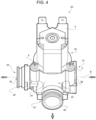
- FIG 4 shows a second embodiment of a hydraulic module 20 used in the hydraulic assembly 100 according to the present invention shown in figure 3 .
- the hydraulic module 20 differs from the hydraulic module 2 exclusively for the presence of a base element 23 having a different structure from that of the base element 3. Therefore, the hydraulic module 20 will be provided with a base element 23, in which the liquid runs in use, and an interactive element 4, similar to the one previously described for the hydraulic module 2, coupled to the base element 23 and configured to interact with the liquid running in the base element 23.
- the interactive element 4 has already been described above for the hydraulic module 2 and therefore will not be described further because it is substantially identical to the one used for the hydraulic module 2.
- the base element 23 comprises a base body 24, a third connector 28, a fourth connector 29 and a fifth connector 30.
- the hydraulic module 20 is thus provided with an additional connector (the fifth connector 30) with respect to the hydraulic module 2 described above.
- a base body 24 is coupled to the third connector 28, to the fourth connector 29, to the fifth connector 30 and to the respective interactive element 4.
- the base body 24 is a hollow body provided with a first opening 31 coupled to the third connector 28, with a second opening 32 coupled to the fourth connector 29, with a third opening 33 coupled to the fifth connector 30 and with a fourth opening 34 coupled to the interactive element 4.
- the base body 24 thus defines a cavity having four openings (not shown in the accompanying figures) in which the liquid runs in use.
- the third connector 28, the fourth connector 29, the fifth connector 30 and the interactive element 4 are in fluid communication with the cavity defined by the base body 24.
- the cavity is shaped so as to convey the input liquid through the third connector 28, the fourth connector 29 and the fifth connector 30, towards the interactive element 4 so as to promote the interaction between the liquid and the interactive element 4.
- the third connector 28, the fourth connector 29 and the fifth connector 30 are made in one piece with the base body 24, while the interactive element 4 is coupled to the base body 7 in three points (only two of which are shown in figure 3 ) by means of the fastening screws 5.
- the liquid enters through the third connector 28, exits through the fourth connector 29 and interacts with the interactive element 4 exiting through the fifth connector 30 (as indicated by the arrows in figure 3 ) in use.
- liquid may run in the opposite direction, according to the configuration of the hydraulic assembly 1 in which the modular element 2 is comprised.
- the third connector 28 and the fourth connector 29 can be mutually coupled.
- the third connector 28 is female while the fourth connector 29 is male.
- each base element 23 can be coupled directly to a further base element 23 without using interconnection elements and so as to define a modular structure of the hydraulic assembly 1.
- the third connector 28 of the hydraulic module 20 can be coupled to the second connector 9 of the hydraulic module 2 and a fourth connector 29 of the hydraulic module 20 can be coupled also to the first connector 8 of the hydraulic module 2.
- the fifth connector 30 can be coupled to the third connector 28. Therefore, the fifth connector 30 of a hydraulic module 20 can be coupled directly to the third connector 28 of a further hydraulic module 20 without using interconnection elements and so as to define a modular structure of the hydraulic assembly 1. According to a variant (not shown), the fifth connector 30 can be coupled to the fourth connector 29.
- the fifth connector 30 of the hydraulic module 20 can also be coupled to the first connector 8 of the hydraulic module 2. Therefore, it is possible to couple hydraulic modules 2 to hydraulic modules 20 without needing to use interconnection elements as shown in the hydraulic assembly 100 in figure 3 .
- the third connector 28 and the fourth connector 29 are arranged aligned along an axis B, while the fifth connector 30 is arranged transversely with respect to the third connector 28 and the fourth connector 29.
- the third connector 28 and the fourth connector 29 and the fifth connector 30 are configured so as to define a quick coupling by means of quick and/or short movements, and preferably without using tools/accessories.
- the third connector 28, the fourth connector 29 and the fifth connector 30 are shaped so as to define a coupling of the bayonet type.
- a variant (not shown) provides for the third connector 28, the fourth connector 29 and the fifth connector 30 to be made so as to define a snap coupling or a threaded coupling.
- Figure 3 shows a configuration of a hydraulic assembly 100 according to the present invention.
- the hydraulic assembly 100 comprises hydraulic modules 2 (with only two connectors 8 and 9) and hydraulic modules 20 (with three connectors 28 29 30).
- the hydraulic assembly 100 further comprises four L-shaped joint elements 35 which are configured to connect, for example, two distinct hydraulic modules or to connect a hydraulic module to a further L-shaped joint element.
- two joint elements 35 connect a hydraulic module 2 to a hydraulic module 20, while two joint elements 35 connect a hydraulic module 20 to a further joint element 35.
- the joint elements 35 in the non-limitative example shown have bayonet attachment ends.
- the hydraulic assembly according to the present invention may also comprise joint elements having different shapes, e.g. T-shaped joints (not shown).
- the hydraulic assembly 100 further comprises a plurality of adapter elements 36 configured to couple the end connectors of the hydraulic assembly 100 to respective hydraulic elements external to the hydraulic assembly 100 (not shown for the sake of simplicity in the appended figures).
- the adapter elements 36 have a bayonet type end which can be coupled to the connectors of the hydraulic modules 2 and 20, and an end shaped so as to be coupled to the external hydraulic element having, for example, a threaded male end.
Landscapes
- Health & Medical Sciences (AREA)
- Life Sciences & Earth Sciences (AREA)
- Engineering & Computer Science (AREA)
- Hydrology & Water Resources (AREA)
- Public Health (AREA)
- Water Supply & Treatment (AREA)
- Physics & Mathematics (AREA)
- Fluid Mechanics (AREA)
- Quick-Acting Or Multi-Walled Pipe Joints (AREA)
- Fluid-Pressure Circuits (AREA)
Applications Claiming Priority (2)
| Application Number | Priority Date | Filing Date | Title |
|---|---|---|---|
| ITMI2014U000106U ITMI20140106U1 (it) | 2014-03-17 | 2014-03-17 | Gruppo idraulico per il controllo di un liquido |
| PCT/IB2015/051960 WO2015140720A1 (en) | 2014-03-17 | 2015-03-17 | Hydraulic assembly for controlling a liquid |
Publications (3)
| Publication Number | Publication Date |
|---|---|
| EP3119944A1 EP3119944A1 (en) | 2017-01-25 |
| EP3119944C0 EP3119944C0 (en) | 2023-09-20 |
| EP3119944B1 true EP3119944B1 (en) | 2023-09-20 |
Family
ID=53005603
Family Applications (1)
| Application Number | Title | Priority Date | Filing Date |
|---|---|---|---|
| EP15718606.5A Active EP3119944B1 (en) | 2014-03-17 | 2015-03-17 | Hydraulic assembly for controlling a liquid |
Country Status (9)
| Country | Link |
|---|---|
| US (1) | US10370831B2 (pl) |
| EP (1) | EP3119944B1 (pl) |
| CN (1) | CN106536830B (pl) |
| BR (1) | BR112016021359B1 (pl) |
| CA (1) | CA2942868C (pl) |
| IT (1) | ITMI20140106U1 (pl) |
| MX (1) | MX374625B (pl) |
| PL (1) | PL3119944T3 (pl) |
| WO (1) | WO2015140720A1 (pl) |
Citations (2)
| Publication number | Priority date | Publication date | Assignee | Title |
|---|---|---|---|---|
| US4524807A (en) * | 1982-05-21 | 1985-06-25 | Humphrey Products Company | Snap-together modular manifold construction |
| US6568713B1 (en) * | 1999-05-20 | 2003-05-27 | Comap Abbeville Sa | Liquid distribution collector module and fixing system for said modules |
Family Cites Families (17)
| Publication number | Priority date | Publication date | Assignee | Title |
|---|---|---|---|---|
| US3560027A (en) * | 1967-02-20 | 1971-02-02 | Gra Tec Inc | Coupling assembly |
| US3506029A (en) * | 1968-06-28 | 1970-04-14 | Amp Inc | Manifold sections to construct a manifold |
| FR2581157B1 (fr) * | 1985-04-29 | 1987-05-29 | Legris Sa | Perfectionnement a la distribution de fluides en conduits multiples. |
| US5089131A (en) * | 1988-11-08 | 1992-02-18 | Halliburton Company | Corrosion resistant filter unit |
| US5178191A (en) * | 1990-09-05 | 1993-01-12 | Newmatic Controls Inc. | Modular pneumatic control systems |
| DE19534285A1 (de) * | 1995-09-15 | 1997-03-20 | Bosch Gmbh Robert | Elektromagnetisch betätigbares pneumatisches Wegeventil |
| US5855224A (en) * | 1996-07-11 | 1999-01-05 | Watts Investment Company | Flapper check valve |
| JPH10300000A (ja) * | 1997-02-28 | 1998-11-13 | Benkan Corp | 集積化ガス制御装置 |
| DE29806644U1 (de) | 1998-04-11 | 1998-08-27 | Armaturenfabrik Wallisellen Ag, Wallisellen | Wasserleitungsgehäuse und Tandem zweier solcher Gehäuse |
| US6058975A (en) * | 1999-08-26 | 2000-05-09 | Hui-Chen; Chao | Connection member of water control valve |
| US6929032B2 (en) * | 2003-04-02 | 2005-08-16 | Sea Tech, Inc. | Manifold |
| US7370674B2 (en) * | 2004-02-20 | 2008-05-13 | Michael Doyle | Modular fluid distribution system |
| US7261122B2 (en) * | 2005-03-29 | 2007-08-28 | Imi Norgren, Inc. | Valve for an expandable gas or fluid distribution system |
| US7261121B2 (en) * | 2005-03-29 | 2007-08-28 | Norgren, Inc. | Expandable gas or fluid distribution system |
| CN101603554B (zh) * | 2009-02-10 | 2011-11-02 | 上海人豪液压技术有限公司 | 组合式液压控制阀 |
| US8833390B2 (en) * | 2011-05-31 | 2014-09-16 | Mueller International, Llc | Valve meter assembly and method |
| CN102913495B (zh) * | 2012-09-28 | 2015-05-20 | 上海人豪液压技术有限公司 | 采用紧凑型二通插装阀的模块化组合式电液多路阀系统 |
-
2014
- 2014-03-17 IT ITMI2014U000106U patent/ITMI20140106U1/it unknown
-
2015
- 2015-03-17 CN CN201580024686.0A patent/CN106536830B/zh active Active
- 2015-03-17 CA CA2942868A patent/CA2942868C/en active Active
- 2015-03-17 EP EP15718606.5A patent/EP3119944B1/en active Active
- 2015-03-17 PL PL15718606.5T patent/PL3119944T3/pl unknown
- 2015-03-17 MX MX2016011989A patent/MX374625B/es active IP Right Grant
- 2015-03-17 US US15/126,505 patent/US10370831B2/en active Active
- 2015-03-17 BR BR112016021359-9A patent/BR112016021359B1/pt active IP Right Grant
- 2015-03-17 WO PCT/IB2015/051960 patent/WO2015140720A1/en not_active Ceased
Patent Citations (2)
| Publication number | Priority date | Publication date | Assignee | Title |
|---|---|---|---|---|
| US4524807A (en) * | 1982-05-21 | 1985-06-25 | Humphrey Products Company | Snap-together modular manifold construction |
| US6568713B1 (en) * | 1999-05-20 | 2003-05-27 | Comap Abbeville Sa | Liquid distribution collector module and fixing system for said modules |
Also Published As
| Publication number | Publication date |
|---|---|
| CA2942868A1 (en) | 2015-09-24 |
| BR112016021359B1 (pt) | 2022-02-08 |
| CA2942868C (en) | 2022-07-12 |
| PL3119944T3 (pl) | 2024-02-19 |
| US20170089048A1 (en) | 2017-03-30 |
| BR112016021359A2 (pl) | 2017-08-15 |
| WO2015140720A1 (en) | 2015-09-24 |
| EP3119944C0 (en) | 2023-09-20 |
| ITMI20140106U1 (it) | 2015-09-17 |
| US10370831B2 (en) | 2019-08-06 |
| CN106536830B (zh) | 2019-12-24 |
| CN106536830A (zh) | 2017-03-22 |
| MX374625B (es) | 2025-03-06 |
| EP3119944A1 (en) | 2017-01-25 |
| MX2016011989A (es) | 2017-04-13 |
Similar Documents
| Publication | Publication Date | Title |
|---|---|---|
| ES2961841T3 (es) | Conjunto hidráulico para controlar un líquido | |
| RU2507695C2 (ru) | Передатчик ввода-вывода технологического процесса с двухпроводным контуром, получающий питание из двухпроводного контура | |
| MX342035B (es) | Sistema de control de flujo de fluido para el interior de pozos que tiene un modulo fluidico con una red en puente y metodo de uso del mismo. | |
| CN108368946A (zh) | 滞后式流体阀门 | |
| JP2017048801A (ja) | 配管接続構造 | |
| CN103672038A (zh) | 一种液体流向转换装置 | |
| US20150096635A1 (en) | Valve with air-gap provision to prevent backflow | |
| EP3119944B1 (en) | Hydraulic assembly for controlling a liquid | |
| RU2678813C1 (ru) | Узел водопропускной панели для водоочистителя и водоочиститель, имеющий такой узел | |
| JP2024144573A (ja) | 流路切換システム | |
| CN104455798A (zh) | 一种多级伸缩压力油管 | |
| CN203082272U (zh) | 一种三通阀 | |
| CN210424044U (zh) | 一种双出水软管 | |
| CN202939506U (zh) | 平面安装手动或自动控制流体多路集成单元 | |
| WO2015168351A1 (en) | Fluid sample system and method | |
| CN103449588A (zh) | 一种污水处理可拆卸的中试实验装置 | |
| JP6518501B2 (ja) | 流体制御装置用継手、流体制御装置用開閉弁および流体制御装置 | |
| CN204039159U (zh) | 一种龙头上带有显示控制面板的水处理系统 | |
| EP1935471B9 (en) | Device for treating and filtering water | |
| CN207297917U (zh) | 一种可调节式液压阀结构 | |
| CN220016183U (zh) | 一种分流阀 | |
| CN108799548B (zh) | 一种阀芯集成系统及厨房龙头集成系统 | |
| CN204042109U (zh) | 免维护型限流阀 | |
| CN108266556A (zh) | 一种磁力推吸开关接头 | |
| CN104534083A (zh) | 一种双离合器变速器换挡用液压系统 |
Legal Events
| Date | Code | Title | Description |
|---|---|---|---|
| STAA | Information on the status of an ep patent application or granted ep patent |
Free format text: STATUS: THE INTERNATIONAL PUBLICATION HAS BEEN MADE |
|
| PUAI | Public reference made under article 153(3) epc to a published international application that has entered the european phase |
Free format text: ORIGINAL CODE: 0009012 |
|
| STAA | Information on the status of an ep patent application or granted ep patent |
Free format text: STATUS: REQUEST FOR EXAMINATION WAS MADE |
|
| 17P | Request for examination filed |
Effective date: 20160919 |
|
| AK | Designated contracting states |
Kind code of ref document: A1 Designated state(s): AL AT BE BG CH CY CZ DE DK EE ES FI FR GB GR HR HU IE IS IT LI LT LU LV MC MK MT NL NO PL PT RO RS SE SI SK SM TR |
|
| AX | Request for extension of the european patent |
Extension state: BA ME |
|
| DAV | Request for validation of the european patent (deleted) | ||
| DAX | Request for extension of the european patent (deleted) | ||
| STAA | Information on the status of an ep patent application or granted ep patent |
Free format text: STATUS: EXAMINATION IS IN PROGRESS |
|
| 17Q | First examination report despatched |
Effective date: 20190829 |
|
| GRAP | Despatch of communication of intention to grant a patent |
Free format text: ORIGINAL CODE: EPIDOSNIGR1 |
|
| STAA | Information on the status of an ep patent application or granted ep patent |
Free format text: STATUS: GRANT OF PATENT IS INTENDED |
|
| INTG | Intention to grant announced |
Effective date: 20230412 |
|
| P01 | Opt-out of the competence of the unified patent court (upc) registered |
Effective date: 20230418 |
|
| GRAS | Grant fee paid |
Free format text: ORIGINAL CODE: EPIDOSNIGR3 |
|
| GRAA | (expected) grant |
Free format text: ORIGINAL CODE: 0009210 |
|
| STAA | Information on the status of an ep patent application or granted ep patent |
Free format text: STATUS: THE PATENT HAS BEEN GRANTED |
|
| AK | Designated contracting states |
Kind code of ref document: B1 Designated state(s): AL AT BE BG CH CY CZ DE DK EE ES FI FR GB GR HR HU IE IS IT LI LT LU LV MC MK MT NL NO PL PT RO RS SE SI SK SM TR |
|
| REG | Reference to a national code |
Ref country code: GB Ref legal event code: FG4D |
|
| REG | Reference to a national code |
Ref country code: CH Ref legal event code: EP |
|
| REG | Reference to a national code |
Ref country code: DE Ref legal event code: R096 Ref document number: 602015085753 Country of ref document: DE |
|
| REG | Reference to a national code |
Ref country code: IE Ref legal event code: FG4D |
|
| P04 | Withdrawal of opt-out of the competence of the unified patent court (upc) registered |
Effective date: 20231023 |
|
| U01 | Request for unitary effect filed |
Effective date: 20231020 |
|
| U07 | Unitary effect registered |
Designated state(s): AT BE BG DE DK EE FI FR IT LT LU LV MT NL PT SE SI Effective date: 20231026 |
|
| PG25 | Lapsed in a contracting state [announced via postgrant information from national office to epo] |
Ref country code: GR Free format text: LAPSE BECAUSE OF FAILURE TO SUBMIT A TRANSLATION OF THE DESCRIPTION OR TO PAY THE FEE WITHIN THE PRESCRIBED TIME-LIMIT Effective date: 20231221 |
|
| PG25 | Lapsed in a contracting state [announced via postgrant information from national office to epo] |
Ref country code: RS Free format text: LAPSE BECAUSE OF FAILURE TO SUBMIT A TRANSLATION OF THE DESCRIPTION OR TO PAY THE FEE WITHIN THE PRESCRIBED TIME-LIMIT Effective date: 20230920 Ref country code: NO Free format text: LAPSE BECAUSE OF FAILURE TO SUBMIT A TRANSLATION OF THE DESCRIPTION OR TO PAY THE FEE WITHIN THE PRESCRIBED TIME-LIMIT Effective date: 20231220 Ref country code: HR Free format text: LAPSE BECAUSE OF FAILURE TO SUBMIT A TRANSLATION OF THE DESCRIPTION OR TO PAY THE FEE WITHIN THE PRESCRIBED TIME-LIMIT Effective date: 20230920 Ref country code: GR Free format text: LAPSE BECAUSE OF FAILURE TO SUBMIT A TRANSLATION OF THE DESCRIPTION OR TO PAY THE FEE WITHIN THE PRESCRIBED TIME-LIMIT Effective date: 20231221 |
|
| REG | Reference to a national code |
Ref country code: ES Ref legal event code: FG2A Ref document number: 2961841 Country of ref document: ES Kind code of ref document: T3 Effective date: 20240314 |
|
| PG25 | Lapsed in a contracting state [announced via postgrant information from national office to epo] |
Ref country code: IS Free format text: LAPSE BECAUSE OF FAILURE TO SUBMIT A TRANSLATION OF THE DESCRIPTION OR TO PAY THE FEE WITHIN THE PRESCRIBED TIME-LIMIT Effective date: 20240120 |
|
| U20 | Renewal fee for the european patent with unitary effect paid |
Year of fee payment: 10 Effective date: 20240315 |
|
| PG25 | Lapsed in a contracting state [announced via postgrant information from national office to epo] |
Ref country code: SM Free format text: LAPSE BECAUSE OF FAILURE TO SUBMIT A TRANSLATION OF THE DESCRIPTION OR TO PAY THE FEE WITHIN THE PRESCRIBED TIME-LIMIT Effective date: 20230920 Ref country code: IS Free format text: LAPSE BECAUSE OF FAILURE TO SUBMIT A TRANSLATION OF THE DESCRIPTION OR TO PAY THE FEE WITHIN THE PRESCRIBED TIME-LIMIT Effective date: 20240120 Ref country code: CZ Free format text: LAPSE BECAUSE OF FAILURE TO SUBMIT A TRANSLATION OF THE DESCRIPTION OR TO PAY THE FEE WITHIN THE PRESCRIBED TIME-LIMIT Effective date: 20230920 Ref country code: SK Free format text: LAPSE BECAUSE OF FAILURE TO SUBMIT A TRANSLATION OF THE DESCRIPTION OR TO PAY THE FEE WITHIN THE PRESCRIBED TIME-LIMIT Effective date: 20230920 |
|
| REG | Reference to a national code |
Ref country code: DE Ref legal event code: R097 Ref document number: 602015085753 Country of ref document: DE |
|
| PLBE | No opposition filed within time limit |
Free format text: ORIGINAL CODE: 0009261 |
|
| STAA | Information on the status of an ep patent application or granted ep patent |
Free format text: STATUS: NO OPPOSITION FILED WITHIN TIME LIMIT |
|
| 26N | No opposition filed |
Effective date: 20240621 |
|
| PG25 | Lapsed in a contracting state [announced via postgrant information from national office to epo] |
Ref country code: MC Free format text: LAPSE BECAUSE OF FAILURE TO SUBMIT A TRANSLATION OF THE DESCRIPTION OR TO PAY THE FEE WITHIN THE PRESCRIBED TIME-LIMIT Effective date: 20230920 |
|
| PG25 | Lapsed in a contracting state [announced via postgrant information from national office to epo] |
Ref country code: MC Free format text: LAPSE BECAUSE OF FAILURE TO SUBMIT A TRANSLATION OF THE DESCRIPTION OR TO PAY THE FEE WITHIN THE PRESCRIBED TIME-LIMIT Effective date: 20230920 |
|
| P05 | Withdrawal of opt-out of the competence of the unified patent court (upc) changed |
Free format text: CASE NUMBER: APP_582278/2023 Effective date: 20231026 |
|
| PG25 | Lapsed in a contracting state [announced via postgrant information from national office to epo] |
Ref country code: IE Free format text: LAPSE BECAUSE OF NON-PAYMENT OF DUE FEES Effective date: 20240317 |
|
| PG25 | Lapsed in a contracting state [announced via postgrant information from national office to epo] |
Ref country code: IE Free format text: LAPSE BECAUSE OF NON-PAYMENT OF DUE FEES Effective date: 20240317 |
|
| U20 | Renewal fee for the european patent with unitary effect paid |
Year of fee payment: 11 Effective date: 20250311 |
|
| PGFP | Annual fee paid to national office [announced via postgrant information from national office to epo] |
Ref country code: ES Payment date: 20250417 Year of fee payment: 11 |
|
| PGFP | Annual fee paid to national office [announced via postgrant information from national office to epo] |
Ref country code: CH Payment date: 20250401 Year of fee payment: 11 |
|
| PG25 | Lapsed in a contracting state [announced via postgrant information from national office to epo] |
Ref country code: CY Free format text: LAPSE BECAUSE OF FAILURE TO SUBMIT A TRANSLATION OF THE DESCRIPTION OR TO PAY THE FEE WITHIN THE PRESCRIBED TIME-LIMIT; INVALID AB INITIO Effective date: 20150317 |
|
| PG25 | Lapsed in a contracting state [announced via postgrant information from national office to epo] |
Ref country code: HU Free format text: LAPSE BECAUSE OF FAILURE TO SUBMIT A TRANSLATION OF THE DESCRIPTION OR TO PAY THE FEE WITHIN THE PRESCRIBED TIME-LIMIT; INVALID AB INITIO Effective date: 20150317 |
|
| PG25 | Lapsed in a contracting state [announced via postgrant information from national office to epo] |
Ref country code: TR Free format text: LAPSE BECAUSE OF FAILURE TO SUBMIT A TRANSLATION OF THE DESCRIPTION OR TO PAY THE FEE WITHIN THE PRESCRIBED TIME-LIMIT Effective date: 20230920 |
|
| REG | Reference to a national code |
Ref country code: CH Ref legal event code: U11 Free format text: ST27 STATUS EVENT CODE: U-0-0-U10-U11 (AS PROVIDED BY THE NATIONAL OFFICE) Effective date: 20260401 |
|
| U20 | Renewal fee for the european patent with unitary effect paid |
Year of fee payment: 12 Effective date: 20260304 |
|
| PGFP | Annual fee paid to national office [announced via postgrant information from national office to epo] |
Ref country code: GB Payment date: 20260319 Year of fee payment: 12 |
|
| PGFP | Annual fee paid to national office [announced via postgrant information from national office to epo] |
Ref country code: RO Payment date: 20260312 Year of fee payment: 12 |
|
| PGFP | Annual fee paid to national office [announced via postgrant information from national office to epo] |
Ref country code: PL Payment date: 20260304 Year of fee payment: 12 |