EP3118713A1 - Input device and electronic apparatus - Google Patents
Input device and electronic apparatus Download PDFInfo
- Publication number
- EP3118713A1 EP3118713A1 EP16179115.7A EP16179115A EP3118713A1 EP 3118713 A1 EP3118713 A1 EP 3118713A1 EP 16179115 A EP16179115 A EP 16179115A EP 3118713 A1 EP3118713 A1 EP 3118713A1
- Authority
- EP
- European Patent Office
- Prior art keywords
- hook
- arm member
- input device
- input
- contact
- Prior art date
- Legal status (The legal status is an assumption and is not a legal conclusion. Google has not performed a legal analysis and makes no representation as to the accuracy of the status listed.)
- Granted
Links
Images


Classifications
-
- G—PHYSICS
- G06—COMPUTING OR CALCULATING; COUNTING
- G06F—ELECTRIC DIGITAL DATA PROCESSING
- G06F1/00—Details not covered by groups G06F3/00 - G06F13/00 and G06F21/00
- G06F1/16—Constructional details or arrangements
- G06F1/1613—Constructional details or arrangements for portable computers
- G06F1/1633—Constructional details or arrangements of portable computers not specific to the type of enclosures covered by groups G06F1/1615 - G06F1/1626
- G06F1/1662—Details related to the integrated keyboard
- G06F1/1671—Special purpose buttons or auxiliary keyboards, e.g. retractable mini keypads, keypads or buttons that remain accessible at closed laptop
-
- G—PHYSICS
- G06—COMPUTING OR CALCULATING; COUNTING
- G06F—ELECTRIC DIGITAL DATA PROCESSING
- G06F3/00—Input arrangements for transferring data to be processed into a form capable of being handled by the computer; Output arrangements for transferring data from processing unit to output unit, e.g. interface arrangements
- G06F3/01—Input arrangements or combined input and output arrangements for interaction between user and computer
- G06F3/02—Input arrangements using manually operated switches, e.g. using keyboards or dials
- G06F3/0202—Constructional details or processes of manufacture of the input device
-
- G—PHYSICS
- G06—COMPUTING OR CALCULATING; COUNTING
- G06F—ELECTRIC DIGITAL DATA PROCESSING
- G06F1/00—Details not covered by groups G06F3/00 - G06F13/00 and G06F21/00
- G06F1/16—Constructional details or arrangements
- G06F1/1613—Constructional details or arrangements for portable computers
- G06F1/1633—Constructional details or arrangements of portable computers not specific to the type of enclosures covered by groups G06F1/1615 - G06F1/1626
- G06F1/1662—Details related to the integrated keyboard
-
- G—PHYSICS
- G06—COMPUTING OR CALCULATING; COUNTING
- G06F—ELECTRIC DIGITAL DATA PROCESSING
- G06F1/00—Details not covered by groups G06F3/00 - G06F13/00 and G06F21/00
- G06F1/16—Constructional details or arrangements
- G06F1/1613—Constructional details or arrangements for portable computers
- G06F1/1615—Constructional details or arrangements for portable computers with several enclosures having relative motions, each enclosure supporting at least one I/O or computing function
- G06F1/1616—Constructional details or arrangements for portable computers with several enclosures having relative motions, each enclosure supporting at least one I/O or computing function with folding flat displays, e.g. laptop computers or notebooks having a clamshell configuration, with body parts pivoting to an open position around an axis parallel to the plane they define in closed position
-
- G—PHYSICS
- G06—COMPUTING OR CALCULATING; COUNTING
- G06F—ELECTRIC DIGITAL DATA PROCESSING
- G06F1/00—Details not covered by groups G06F3/00 - G06F13/00 and G06F21/00
- G06F1/16—Constructional details or arrangements
- G06F1/1613—Constructional details or arrangements for portable computers
- G06F1/1633—Constructional details or arrangements of portable computers not specific to the type of enclosures covered by groups G06F1/1615 - G06F1/1626
- G06F1/1684—Constructional details or arrangements related to integrated I/O peripherals not covered by groups G06F1/1635 - G06F1/1675
- G06F1/169—Constructional details or arrangements related to integrated I/O peripherals not covered by groups G06F1/1635 - G06F1/1675 the I/O peripheral being an integrated pointing device, e.g. trackball in the palm rest area, mini-joystick integrated between keyboard keys, touch pads or touch stripes
-
- G—PHYSICS
- G06—COMPUTING OR CALCULATING; COUNTING
- G06F—ELECTRIC DIGITAL DATA PROCESSING
- G06F3/00—Input arrangements for transferring data to be processed into a form capable of being handled by the computer; Output arrangements for transferring data from processing unit to output unit, e.g. interface arrangements
- G06F3/01—Input arrangements or combined input and output arrangements for interaction between user and computer
- G06F3/03—Arrangements for converting the position or the displacement of a member into a coded form
- G06F3/033—Pointing devices displaced or positioned by the user, e.g. mice, trackballs, pens or joysticks; Accessories therefor
- G06F3/0354—Pointing devices displaced or positioned by the user, e.g. mice, trackballs, pens or joysticks; Accessories therefor with detection of two-dimensional [2D] relative movements between the device, or an operating part thereof, and a plane or surface, e.g. 2D mice, trackballs, pens or pucks
- G06F3/03547—Touch pads, in which fingers can move on a surface
-
- H—ELECTRICITY
- H01—ELECTRIC ELEMENTS
- H01H—ELECTRIC SWITCHES; RELAYS; SELECTORS; EMERGENCY PROTECTIVE DEVICES
- H01H13/00—Switches having rectilinearly-movable operating part or parts adapted for pushing or pulling in one direction only, e.g. push-button switch
- H01H13/50—Switches having rectilinearly-movable operating part or parts adapted for pushing or pulling in one direction only, e.g. push-button switch having a single operating member
- H01H13/52—Switches having rectilinearly-movable operating part or parts adapted for pushing or pulling in one direction only, e.g. push-button switch having a single operating member the contact returning to its original state immediately upon removal of operating force, e.g. bell-push switch
-
- G—PHYSICS
- G06—COMPUTING OR CALCULATING; COUNTING
- G06F—ELECTRIC DIGITAL DATA PROCESSING
- G06F2203/00—Indexing scheme relating to G06F3/00 - G06F3/048
- G06F2203/041—Indexing scheme relating to G06F3/041 - G06F3/045
- G06F2203/04105—Pressure sensors for measuring the pressure or force exerted on the touch surface without providing the touch position
-
- H—ELECTRICITY
- H01—ELECTRIC ELEMENTS
- H01H—ELECTRIC SWITCHES; RELAYS; SELECTORS; EMERGENCY PROTECTIVE DEVICES
- H01H2215/00—Tactile feedback
- H01H2215/03—Sound
-
- H—ELECTRICITY
- H01—ELECTRIC ELEMENTS
- H01H—ELECTRIC SWITCHES; RELAYS; SELECTORS; EMERGENCY PROTECTIVE DEVICES
- H01H2217/00—Facilitation of operation; Human engineering
- H01H2217/006—Different feeling for different switch sites
-
- H—ELECTRICITY
- H01—ELECTRIC ELEMENTS
- H01H—ELECTRIC SWITCHES; RELAYS; SELECTORS; EMERGENCY PROTECTIVE DEVICES
- H01H2217/00—Facilitation of operation; Human engineering
- H01H2217/02—After travel
-
- H—ELECTRICITY
- H01—ELECTRIC ELEMENTS
- H01H—ELECTRIC SWITCHES; RELAYS; SELECTORS; EMERGENCY PROTECTIVE DEVICES
- H01H2221/00—Actuators
- H01H2221/062—Damping vibrations
Definitions
- the present invention relates to an input device including an operation-input part to receive an input operation that is vertically movably supported above a base-plate, and an electronic apparatus including such an input device.
- a laptop personal computer for example, is provided with various input devices as an alternative of a mouse, such as a touch pad and a pointing device, in addition to a keyboard device.
- a touch pad enables the manipulation of a cursor displayed on a display device in response to a touch operation thereto with a fingertip or a pen tip.
- an operation-input part to receive an input operation is vertically movably supported above a base-plate.
- a plurality of pseudo button areas is configured on a touch surface of the touch pad (operation-input part), which allows an operator to perform an input operation corresponding to each pseudo button area by pressing (clicking) the touch pad while touching the corresponding pseudo button area.
- the above-mentioned input device is provided with a member to specify the ascending limit (position) of the touch pad.
- the touch pad comes into contact with such a member to specify the ascending limit, so that sound (rebound sound) occurs there.
- sound return sound
- the present invention aims to provide an input device capable of reducing sound that is generated when the pressed operation-input part returns to the original position, and an electronic apparatus including such an input device.
- An input device includes an operation-input part to receive an input operation that is vertically movably supported above a base plate, wherein the base plate has a hook standing toward the operation-input part, the operation-input part has an arm member that can come into contact with the hook, a contact of the arm member with the hook specifies an ascending limit of the operation-input part, and at least one of the arm member and the hook has elasticity in their contacting direction.
- the arm member of the operation-input part comes into contact with the hook of the base plate, whereby the ascending limit of the operation-input part is specified. Since at least one of the arm member and the hook has elasticity in their contacting direction, sound (rebound sound) generated from a contact of the arm member with the hook when the pressed operation-input part returns to the original position can be reduced.
- the base plate may have another hook opposed to the hook
- the operation-input part may have another arm member opposed to the arm member
- the other arm member and the other hook can come into contact at a position above the ascending limit of the operation-input part that is specified by a contact with the arm member and the hook.
- the other arm member is configured so as to come into contact with the other hook at a position above the ascending limit of the operation-input part, and therefore a contact between the other arm member and the other hook can prevent detachment of the operation-input part from the base plate even when a large force is applied thereto. That is, these other arm member and other hook function as a retainer, and if a large force leading to a failure to specify the ascending limit by the arm member and the hook, for example, is applied, the retainer can prevent the operation-input part from coming off from the base plate.
- the other arm member is configured so as to come into contact with the other hook at a position above the ascending limit of the operation-input part. Thereby, when the pressed operation-input part returns to the original position, the arm member and the hook firstly come into contact so as to reduce rebound sound, and the other arm member and the other hook can function as a retainer.
- the other arm member when the arm member has elasticity, the other arm member preferably has higher stiffness than the arm member. In this case, since the other arm member has higher stiffness than that of the arm member, if a large force is applied to the touch pad and the base plate, a contact between the other hook and the other arm member can prevent detachment of the touch pad from the base plate.
- the other hook when the hook has elasticity, the other hook preferably has higher stiffness than the hook. In this case, since the other hook has higher stiffness than that of the hook, if a large force is applied to the touch pad and the base plate, a contact between the other hook and the other arm member can prevent detachment of the touch pad from the base plate.
- the arm member and the other arm member may have protruding pieces at the forward ends that protrude in their opposed direction, and the hook and the other hook can come into contact with their corresponding protruding pieces.
- the arm member protrudes in a direction intersecting with an operating direction of a press operation to the operation-input part, and a forward end part of the arm member comes into contact with the hook.
- the arm member protrudes in the direction intersecting with the direction of the press operation to the operation-input part, an increase in the dimension of the input device in the thickness direction can be avoided, meaning that the input device can be made thinner.
- the operation-input part may include a touch pad that can receive a touch operation and can receive a press operation.
- An electronic apparatus includes: the input device, a keyboard device, and a display device to display in accordance with an input operation through the input device and the keyboard device.
- the arm member and the hook since at least one of the arm member and the hook has elasticity in their contacting direction, sound (rebound sound) generated when the pressed operation-input part returns to the original position can be reduced.
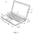
- Fig. 1 is a perspective view of an electronic apparatus 12 including an input device 10 according to one embodiment of the present invention.
- the side near the operator is called the front side (forward)
- the back side is called the rear side (rearward)
- the thickness direction of a body chassis 14 making up the electronic apparatus 12 is called the vertical direction
- the width direction thereof is called the horizontal direction.
- the electronic apparatus 12 is a laptop PC including the body chassis 14 having the input device 10 and a keyboard device 16, and a display chassis 18 having a display unit 18a, such as a liquid crystal display.
- the display chassis 18 is coupled openably/closably to the body chassis 14 via a pair of left and right hinges 19, 19.
- the body chassis 14 internally stores various electronic components, such as a board, a processing unit, a hard disk device, and a memory, which are not illustrated.
- the input device 10 and the keyboard device 16 are placed at the front and the rear on a top face 14a of the body chassis 14, respectively.
- a pointing stick 20 is provided at a substantially center of the keyboard device 16.
- the pointing stick 20 is to manipulate a cursor (mouse pointer) displayed on the display unit 18a, which is input means that can be manipulated instead of the mouse.
- the present embodiment exemplifies the configuration where the input device 10 is mounted on the electronic apparatus 12 as a laptop PC as stated above, the input device 10 may be mounted on a keyboard device as a single body to be connected to a desktop PC or the like.
- FIG. 2 is a cross-sectional side view schematically showing the configuration of the input device 10 according to one embodiment of the present invention
- Fig. 3 is a perspective view of the input device 10 shown in Fig. 2 .
- the input device 10 includes a touch pad (operation-input part) 22 to receive a touch operation of an operator by bringing a fingertip or the like closer to or into contact with there, and three press buttons 24a, 24b and 24c arranged along the rear end part of the touch pad 22.
- the touch pad 22 and the press buttons 24a to 24c are supported on the side of the upper face of the base plate 26 that is a metal plate member.
- the press buttons 24a to 24c operate in relation to the cursor manipulation using the pointing stick 20 or the touch pad 22, and are click-operation buttons corresponding to a left button, a center button and a right button of a typical mouse, respectively.
- the press buttons 24a to 24c may be placed close to the forward end of the touch pad 22, or may be disposed with a frame of the body chassis 14 put between the touch pad 22 and the buttons.
- the press buttons 24a to 24c have their rear ends 28 that rotatably engage with a supporting piece 30 standing from the rear end of the base plate 26, whereby these buttons can swing about the rear-ends 28 as a supporting point. Therefore, when the front-end part of each press button 24a to 24c is pressed, then a rubber dome 32 placed inside is compressed, whereby a switch not illustrated, such as a membrane switch, provided on the upper face of the base plate 26 is turned on.
- the touch pad 22 is configured as a click pad, with which a click operation by pressing also can be performed, in addition to a touch operation.
- pseudo button areas 34a, 34b are configured on a part of a touch operation face 22a as the surface of the touch pad 22 that is close to the front side.
- the pseudo button areas 34a, 34b have their respective areas on the touch operation face 22a defined with coordinates, and are invisible.
- processing or display corresponding to the pseudo button area 34a, 34b is performed.
- the two pseudo button areas 34a and 34b correspond to the left button and the right button of a typical mouse, respectively.
- the touch pad 22 has a three-layered configuration, including a housing plate 40 as a bottom plate that is placed to be opposed to the base plate 26, a board plate (board) 42 that is stacked on the upper face of the housing plate 40 to detect a touch operation to the touch operation face 22a, and a pad plate (pad) 44 that is stacked on the board plate 42, whose surface is the touch operation face 22a to receive a touch operation.
- a housing plate 40 as a bottom plate that is placed to be opposed to the base plate 26
- a board plate (board) 42 that is stacked on the upper face of the housing plate 40 to detect a touch operation to the touch operation face 22a
- a pad plate (pad) 44 that is stacked on the board plate 42, whose surface is the touch operation face 22a to receive a touch operation.
- Fig. 3 omits the illustration of the board plate 42 and the pad plate 44.
- the board plate 42 is a board having a rectangular shape in planar view, which is a sensor to detect a touch operation to the pad plate 44 or a press operation to the touch pad 22.
- the board plate 42 is connected to a board in the body chassis 14 via wiring not illustrated.
- To the board plate 42 not-illustrated wiring from the press buttons 24a to 24c is connected.
- the pad plate 44 is a glass plate or a resin plate having a rectangular shape in planar view, and is fixedly attached to the upper face of the board plate 42 with adhesive, double-faced tape, or the like.
- the board plate 42 is provided with ground line G on the lower face close to the rear end, the ground line being a belt-like conductive part that extends along the horizontal direction (see Fig. 2 ).
- the housing plate 40 is a resin plate having a rectangular shape in planar view, and is a chassis component to hold the board plate 42 and the pad plate 44.
- the board plate 42 is fixedly attached with adhesive, double-faced tape, or the like.
- the housing plate 40 has an inclined-face part 40a at the rear end and near the forward-end face of the press buttons 24a to 24c that is inclined downward to the rear side. Due to such an inclined-face part 40a, the touch pad 22 does not hinder the press operation of the press buttons 24a to 24c.
- a pair of left and right elastic pieces 46 is provided on the front side of the inclined-face part 40a of the housing plate 40 so as to be elongated toward the rear.
- the elastic pieces 46 are formed by cutting away their both left and right lateral parts and rear parts in the thickness direction so as to be a piece like a narrow tongue, whereby they have a cantilever structure to be elastic to some extent.
- Each elastic piece 46 has a nail 46a at the end (rear-end) so as to be displaced to be curved downward.
- the elastic pieces 46 are not fixedly attached to the lower face of the board plate 42, and at least the nails 46a thereof are disposed to have a predetermined gap between the upper faces thereof and the board plate 42, whereby protruding pieces 50 that are formed by cutting the upper face of the base plate 26 so as to lift it up described later are sandwiched between the upper faces of the nails 46a and the lower face of the board plate 42.
- a plurality of engagement pieces 47 are provided on the front side of the inclined-face part 40a of the housing plate 40 so as to have a shape substantially similar to that of the nails 46a of the elastic pieces 46 and to be elongated short to the rear.
- Each of the engagement pieces 47 also engages with the corresponding protruding piece 50 that is cut to lift up from the base plate 26 (see Fig. 2 and Fig. 3 ).
- a not-illustrated guide structure vertically guides the housing plate 40 relative to the base plate 26, so that the housing plate 40 is configured to move vertically while moving the engagement portions of the elastic pieces 46 and the engagement pieces 47 with their corresponding protruding pieces 50 rearward and forward to some extent.
- a detection switch 55 is provided at a substantially center part on the lower face of the housing plate 40 close to the forward end.
- the detection switch 55 is to issue a predetermined detection signal when the touch pad 22 is pressed.
- the detection switch 55 is a metal dome switch, for example, that bulges downward from the lower face of the housing plate 40, which is turned on when the touch pad 22 is pressed until the switch comes into contact with the base plate 26, and this ON signal is detected by the board plate 42.
- the protruding pieces 50 are formed to stand from the upper face of the base plate 26.
- Each protruding piece 50 is formed like an angular U-letter shape in lateral view that has an abutting plate 50a at the upper end that is bent toward the rear when a part of the base plate 26 is cut to lift upward.
- a dome-like convex 50b is provided so as to bulge upward.
- the protruding pieces 50 are provided at the positions corresponding to the elastic pieces 46 and the engagement pieces 47 of the housing plate 40.
- an elastic pressing part 56 is disposed, which is formed on the upper face of the base plate 26.
- Fig. 4 is a perspective view showing the major part of the base plate 26 in the input device 10 shown in Fig. 3
- Fig. 5 is a perspective view that is an enlarged view of the major part of the input device 10 shown in Fig. 3
- Fig. 6 schematically shows the major part of the input device 10 in Fig. 3 viewed from the rear face
- Fig. 7 is a perspective view that is an enlarged view of the major part of the housing plate 40 in the input device 10 shown in Fig. 3
- Fig. 6 shows a part of the base plate 26 only (a first hook 61 and a second hook 62) for easier viewing.
- a hook (first hook) 61 standing like a L-letter shape in cross section from the upper face of the base plate 26 toward the touch pad 22 (operation-input part) and another hook (second hook) 62 opposed to this hook 61 are provided at the base plate 26 of a part close to the front end.
- Two of such first hook 61 and second hook 62 are disposed on the left and right of the base plate 26 of a part close to the front end, where the first hook 61 and the second hook 62 of each pair is disposed in the front-back direction (see Fig. 3 ).
- Each latch 70 has an arm member (first arm member) 71 that can come into contact with the first hook 61 and another arm member (second arm member) 72 that can come into contact with the second hook 62.
- the latch 70 has a substantially V-letter shape in a planar view, including the first arm member 71 and the second arm member 72 (see Figs. 5 and 6 ). That is, the first arm member 71 and the second arm member 72 are disposed so that their parts closed to the forward end are spaced from each other.
- first arm member 71 and second arm member 72 protrude in the direction intersecting with the operating direction of the press operation to the touch pad 22, and are configured so that their forward ends can come into contact with the first hook 61 and the second hook 62, respectively.
- the forward ends of the first arm member 71 and the second arm member 72 are provided with protruding pieces 71a and 72a, respectively, that protrude in their opposed direction so that the first hook 61 and the second hook 62 can come into contact with these protruding pieces 71a and 72a.
- the forward ends of the first hook 61 and the first arm member 71 come into contact with vertically, whereby the ascending limit of the touch pad 22 is specified. That is, the first hook 61 and the first arm member 71 are parts that couple in the direction where the housing plate 40 is overlapped with the base plate 26.
- the second hook 62 is disposed at a position higher than the first hook 61, whereby the former does not come into contact with the second arm member 72 when the touch pad 22 is not pressed (see Fig. 9 ).
- the second arm member 72 is configured so that it can come into contact with the second hook 62 at a position above the ascending limit of the touch pad 22.
- the first hook 61 and the first arm member 71 have elasticity in their contacting direction, and in the present embodiment, both of the first hook 61 and the first arm member 71 have elasticity in their contacting direction (vertical direction in Fig. 3 ).
- the first hook 61 has a length from the base end to the forward end that is longer than that of the second hook 62 and has a smaller width, whereby it has elasticity in the vertical direction (see Fig. 4 ).
- the thickness of the first hook 61 may be made smaller, whereby elasticity thereof can be increased.
- the first arm member 71 is made thinner than the second arm member 72 so as to have elasticity.
- the first arm member 71 has a thin part 71b having a thickness L2 that is thinner than the thickness indicated with L3. That is, as shown in Fig. 7 , the thin part 71b is thinner than the second arm member 72 by the thickness L1.
- the second hook 62 has a length from the base end to the forward end that is shorter than that of the first hook 61 and has a larger width, whereby the second hook 62 has high stiffness compared with the first hook 61.
- the second arm member 72 is thicker than the first arm member 71, whereby the second arm member 72 has high stiffness compared with the first arm member 71.
- Fig. 8 is a cross-sectional side view schematically showing the state where the touch pad 22 in the input device 10 according to one embodiment of the present invention is pressed.
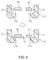
- Fig. 9 is a cross-sectional view taken along the arrow IX-IX of Fig. 5 .
- the upper part of Fig. 9 shows the state where the touch pad 22 is pressed, and the lower part shows the state where the pressed touch pad returns to the original position (the state where it is not pressed).
- the second arm member 72 is configured so as to come into contact with the second hook 62 at a position above the ascending limit of the touch pad 22, and therefore a contact between the second arm member 72 and the second hook 62 can prevent detachment of the touch pad 22 from the base plate 26 even when a large force is applied thereto. That is, these second arm member 72 and second hook 62 function as a retainer, and if a large force leading to a failure to specify the ascending limit of the touch pad 22 by the first arm member 71 and the first hook 61, for example, is applied, the retainer can prevent the touch pad 22 from coming off from the base plate 26.
- the second arm member 72 is configured so as to come into contact with the second hook 62 at a position above the ascending limit of the touch pad 22 by L4. Thereby, when the pressed touch pad 22 of the input device 10 returns to the original position, the first arm member 71 and the first hook 61 firstly come into contact so as to reduce rebound sound, and the second arm member 72 and the second hook 62 can function as a retainer.
- the second arm member 72 of the input device 10 has higher stiffness than that of the first arm member 71, and therefore if a large force is applied to the touch pad 22 and the base plate 26, a contact between the second hook 62 and the second arm member 72 having such high stiffness can function as a retainer reliably, whereby detachment of the touch pad 22 from the base plate 26 can be prevented.
- the second hook 62 of the input device 10 has higher stiffness than that of the first hook 61, and therefore if a large force is applied to the touch pad 22 and the base plate 26, a contact between the second arm member 72 and the second hook 62 having such high stiffness can function as a retainer reliably, whereby detachment of the touch pad 22 from the base plate 26 can be prevented.
- first arm member 71 and the second arm member 72 of the input device 10 protrude in the direction intersecting with the direction of the press operation to the touch pad 22, and therefore an increase in the dimension of the input device 10 in the thickness direction can be avoided, meaning that the input device 10 can be made thinner. It should be noted here that the first arm member 71 and the second arm member 72 preferably protrude in the direction substantially orthogonal to the direction of the press operation to the touch pad 22.
- each latch 70 has a V-letter shape made up of the first arm member 71 and the second arm member 72, when the first hook 61 and the second hook 62 of the base plate 26 are pressed there from the below, the first arm member 71 and the second arm member 72 are pressed apart so as to enable fitting of the first hook 61 and the second hook 62 into the latch 70.
- the first arm member 71 and the second arm member 72 have the protruding pieces 71a and 72a, respectively, at their forward ends that protrude in their opposed direction. Then, the first hook 61 and the second hook 62 can come into contact with these protruding pieces 71a and 72a, respectively.
- each latch has the first arm member and the second arm member, and the latch may not have such a second arm member.
- the base plate may not have a second hook.
- each latch may have two opposed first arm members.
- these first arm members may come into contact with two first hooks, respectively, having elasticity.
- the present invention is applicable also to input devices other than a click pad including the touch pad 22 movably held above the base plate 26.
Landscapes
- Engineering & Computer Science (AREA)
- Theoretical Computer Science (AREA)
- General Engineering & Computer Science (AREA)
- Computer Hardware Design (AREA)
- Physics & Mathematics (AREA)
- Human Computer Interaction (AREA)
- General Physics & Mathematics (AREA)
- Mathematical Physics (AREA)
- Position Input By Displaying (AREA)
Abstract
Description
- The present invention relates to an input device including an operation-input part to receive an input operation that is vertically movably supported above a base-plate, and an electronic apparatus including such an input device.
- A laptop personal computer (laptop PC), for example, is provided with various input devices as an alternative of a mouse, such as a touch pad and a pointing device, in addition to a keyboard device. A touch pad enables the manipulation of a cursor displayed on a display device in response to a touch operation thereto with a fingertip or a pen tip.
- For such an input device including a touch pad, the present applicant proposes the configuration enabling a touch operation and a press operation (input operation) of the touch pad in Patent Document 1. In this configuration, an operation-input part to receive an input operation is vertically movably supported above a base-plate. For instance, a plurality of pseudo button areas is configured on a touch surface of the touch pad (operation-input part), which allows an operator to perform an input operation corresponding to each pseudo button area by pressing (clicking) the touch pad while touching the corresponding pseudo button area.
- [Patent Document 1]
JP 2013-25422 A - Meanwhile, the above-mentioned input device is provided with a member to specify the ascending limit (position) of the touch pad. When the pressed touch pad returns to the original position, the touch pad comes into contact with such a member to specify the ascending limit, so that sound (rebound sound) occurs there. There is a demand to reduce such sound that is generated when a touch pad comes into contact with the member to specify the ascending limit.
- In view of the problem of the conventional techniques, the present invention aims to provide an input device capable of reducing sound that is generated when the pressed operation-input part returns to the original position, and an electronic apparatus including such an input device.
- An input device according to the present invention includes an operation-input part to receive an input operation that is vertically movably supported above a base plate, wherein the base plate has a hook standing toward the operation-input part, the operation-input part has an arm member that can come into contact with the hook, a contact of the arm member with the hook specifies an ascending limit of the operation-input part, and at least one of the arm member and the hook has elasticity in their contacting direction.
- With this configuration, the arm member of the operation-input part comes into contact with the hook of the base plate, whereby the ascending limit of the operation-input part is specified. Since at least one of the arm member and the hook has elasticity in their contacting direction, sound (rebound sound) generated from a contact of the arm member with the hook when the pressed operation-input part returns to the original position can be reduced.
- In the input device according to the present invention, the base plate may have another hook opposed to the hook, the operation-input part may have another arm member opposed to the arm member, and the other arm member and the other hook can come into contact at a position above the ascending limit of the operation-input part that is specified by a contact with the arm member and the hook.
- In this case, the other arm member is configured so as to come into contact with the other hook at a position above the ascending limit of the operation-input part, and therefore a contact between the other arm member and the other hook can prevent detachment of the operation-input part from the base plate even when a large force is applied thereto. That is, these other arm member and other hook function as a retainer, and if a large force leading to a failure to specify the ascending limit by the arm member and the hook, for example, is applied, the retainer can prevent the operation-input part from coming off from the base plate. Herein the other arm member is configured so as to come into contact with the other hook at a position above the ascending limit of the operation-input part. Thereby, when the pressed operation-input part returns to the original position, the arm member and the hook firstly come into contact so as to reduce rebound sound, and the other arm member and the other hook can function as a retainer.
- In the input device according to the present invention, when the arm member has elasticity, the other arm member preferably has higher stiffness than the arm member. In this case, since the other arm member has higher stiffness than that of the arm member, if a large force is applied to the touch pad and the base plate, a contact between the other hook and the other arm member can prevent detachment of the touch pad from the base plate.
- In the input device according to the present invention, when the hook has elasticity, the other hook preferably has higher stiffness than the hook. In this case, since the other hook has higher stiffness than that of the hook, if a large force is applied to the touch pad and the base plate, a contact between the other hook and the other arm member can prevent detachment of the touch pad from the base plate.
- In the input device according to the present invention, the arm member and the other arm member may have protruding pieces at the forward ends that protrude in their opposed direction, and the hook and the other hook can come into contact with their corresponding protruding pieces.
- Preferably in the input device according to the present invention, the arm member protrudes in a direction intersecting with an operating direction of a press operation to the operation-input part, and a forward end part of the arm member comes into contact with the hook. In this case, since the arm member protrudes in the direction intersecting with the direction of the press operation to the operation-input part, an increase in the dimension of the input device in the thickness direction can be avoided, meaning that the input device can be made thinner.
- In the input device according to the present invention, the operation-input part may include a touch pad that can receive a touch operation and can receive a press operation.
- An electronic apparatus according to the present invention includes: the input device, a keyboard device, and a display device to display in accordance with an input operation through the input device and the keyboard device.
- According to the present invention, since at least one of the arm member and the hook has elasticity in their contacting direction, sound (rebound sound) generated when the pressed operation-input part returns to the original position can be reduced.
-
-
Fig. 1 is a perspective view of an electronic apparatus including an input device according to one embodiment of the present invention. -
Fig. 2 is a cross-sectional side view schematically showing the configuration of the input device according to one embodiment of the present invention. -
Fig. 3 is a perspective view of the input device shown inFig. 2 . -
Fig. 4 is a perspective view showing the major part of the base plate in the input device shown inFig. 3 . -
Fig. 5 is a perspective view that is an enlarged view of the major part of the input device shown inFig. 3 . -
Fig. 6 schematically shows the major part of the input device inFig. 3 viewed from the rear face. -
Fig. 7 is a perspective view that is an enlarged view of the major part of the housing plate in the input device shown inFig. 3 . -
Fig. 8 is a cross-sectional side view schematically showing the state where the touch pad in the input device according to one embodiment of the present invention is pressed. -
Fig. 9 is a cross-sectional view taken along the arrow IX-IX ofFig. 5 . - Referring to the attached drawings, the following describes an input device of the present invention by way of an embodiment that is favorable in relationship with an electronic apparatus including this input device.
-
Fig. 1 is a perspective view of anelectronic apparatus 12 including aninput device 10 according to one embodiment of the present invention. In the following descriptions, based on the usage form of theinput device 10 in theelectronic apparatus 12 shown inFig. 1 as a reference, the side near the operator is called the front side (forward), the back side is called the rear side (rearward), the thickness direction of abody chassis 14 making up theelectronic apparatus 12 is called the vertical direction, and the width direction thereof is called the horizontal direction. - As shown in
Fig. 1 , theelectronic apparatus 12 is a laptop PC including thebody chassis 14 having theinput device 10 and akeyboard device 16, and adisplay chassis 18 having adisplay unit 18a, such as a liquid crystal display. Thedisplay chassis 18 is coupled openably/closably to thebody chassis 14 via a pair of left andright hinges - The
body chassis 14 internally stores various electronic components, such as a board, a processing unit, a hard disk device, and a memory, which are not illustrated. Theinput device 10 and thekeyboard device 16 are placed at the front and the rear on atop face 14a of thebody chassis 14, respectively. At a substantially center of thekeyboard device 16, a pointingstick 20 is provided. Thepointing stick 20 is to manipulate a cursor (mouse pointer) displayed on thedisplay unit 18a, which is input means that can be manipulated instead of the mouse. - Although the present embodiment exemplifies the configuration where the
input device 10 is mounted on theelectronic apparatus 12 as a laptop PC as stated above, theinput device 10 may be mounted on a keyboard device as a single body to be connected to a desktop PC or the like. - Next, an example of the configuration of the
input device 10 is described.Fig. 2 is a cross-sectional side view schematically showing the configuration of theinput device 10 according to one embodiment of the present invention, andFig. 3 is a perspective view of theinput device 10 shown inFig. 2 . - As shown in
Fig. 1 andFig. 2 , theinput device 10 includes a touch pad (operation-input part) 22 to receive a touch operation of an operator by bringing a fingertip or the like closer to or into contact with there, and threepress buttons touch pad 22. As shown inFig. 2 andFig. 3 , thetouch pad 22 and thepress buttons 24a to 24c are supported on the side of the upper face of thebase plate 26 that is a metal plate member. - Firstly, the
press buttons 24a to 24c operate in relation to the cursor manipulation using thepointing stick 20 or thetouch pad 22, and are click-operation buttons corresponding to a left button, a center button and a right button of a typical mouse, respectively. Thepress buttons 24a to 24c may be placed close to the forward end of thetouch pad 22, or may be disposed with a frame of thebody chassis 14 put between thetouch pad 22 and the buttons. - As shown in
Fig. 2 , thepress buttons 24a to 24c have theirrear ends 28 that rotatably engage with a supportingpiece 30 standing from the rear end of thebase plate 26, whereby these buttons can swing about the rear-ends 28 as a supporting point. Therefore, when the front-end part of eachpress button 24a to 24c is pressed, then arubber dome 32 placed inside is compressed, whereby a switch not illustrated, such as a membrane switch, provided on the upper face of thebase plate 26 is turned on. - Next, the
touch pad 22 is configured as a click pad, with which a click operation by pressing also can be performed, in addition to a touch operation. - As shown in
Fig. 1 ,pseudo button areas touch operation face 22a as the surface of thetouch pad 22 that is close to the front side. Thepseudo button areas touch operation face 22a defined with coordinates, and are invisible. In response to a press operation of thetouch pad 22 while bringing a fingertip in contact with one of thepseudo button areas pseudo button area pseudo button areas - As shown in
Fig. 2 , thetouch pad 22 has a three-layered configuration, including ahousing plate 40 as a bottom plate that is placed to be opposed to thebase plate 26, a board plate (board) 42 that is stacked on the upper face of thehousing plate 40 to detect a touch operation to thetouch operation face 22a, and a pad plate (pad) 44 that is stacked on theboard plate 42, whose surface is thetouch operation face 22a to receive a touch operation.Fig. 3 omits the illustration of theboard plate 42 and thepad plate 44. - The
board plate 42 is a board having a rectangular shape in planar view, which is a sensor to detect a touch operation to thepad plate 44 or a press operation to thetouch pad 22. Theboard plate 42 is connected to a board in thebody chassis 14 via wiring not illustrated. To theboard plate 42, not-illustrated wiring from thepress buttons 24a to 24c is connected. Thepad plate 44 is a glass plate or a resin plate having a rectangular shape in planar view, and is fixedly attached to the upper face of theboard plate 42 with adhesive, double-faced tape, or the like. Theboard plate 42 is provided with ground line G on the lower face close to the rear end, the ground line being a belt-like conductive part that extends along the horizontal direction (seeFig. 2 ). - As shown in
Fig. 2 andFig. 3 , thehousing plate 40 is a resin plate having a rectangular shape in planar view, and is a chassis component to hold theboard plate 42 and thepad plate 44. On the upper face of thehousing plate 40, theboard plate 42 is fixedly attached with adhesive, double-faced tape, or the like. Thehousing plate 40 has an inclined-face part 40a at the rear end and near the forward-end face of thepress buttons 24a to 24c that is inclined downward to the rear side. Due to such an inclined-face part 40a, thetouch pad 22 does not hinder the press operation of thepress buttons 24a to 24c. - A pair of left and right
elastic pieces 46 is provided on the front side of the inclined-face part 40a of thehousing plate 40 so as to be elongated toward the rear. Theelastic pieces 46 are formed by cutting away their both left and right lateral parts and rear parts in the thickness direction so as to be a piece like a narrow tongue, whereby they have a cantilever structure to be elastic to some extent. Eachelastic piece 46 has anail 46a at the end (rear-end) so as to be displaced to be curved downward. Theelastic pieces 46 are not fixedly attached to the lower face of theboard plate 42, and at least thenails 46a thereof are disposed to have a predetermined gap between the upper faces thereof and theboard plate 42, whereby protrudingpieces 50 that are formed by cutting the upper face of thebase plate 26 so as to lift it up described later are sandwiched between the upper faces of thenails 46a and the lower face of theboard plate 42. - Further, a plurality of
engagement pieces 47 are provided on the front side of the inclined-face part 40a of thehousing plate 40 so as to have a shape substantially similar to that of thenails 46a of theelastic pieces 46 and to be elongated short to the rear. Each of theengagement pieces 47 also engages with the corresponding protrudingpiece 50 that is cut to lift up from the base plate 26 (seeFig. 2 andFig. 3 ). - Since the
elastic pieces 46 and theengagement pieces 47 of thehousing plate 40 rotatably engage with the corresponding protrudingpieces 50 of thebase plate 26, the housing plate 40 (touch pad 22) can swing relative to thebase plate 26 about these engaging portions as the supporting point. Herein in the case of the present embodiment, a not-illustrated guide structure vertically guides thehousing plate 40 relative to thebase plate 26, so that thehousing plate 40 is configured to move vertically while moving the engagement portions of theelastic pieces 46 and theengagement pieces 47 with their correspondingprotruding pieces 50 rearward and forward to some extent. - As shown in
Fig. 2 , adetection switch 55 is provided at a substantially center part on the lower face of thehousing plate 40 close to the forward end. Thedetection switch 55 is to issue a predetermined detection signal when thetouch pad 22 is pressed. Thedetection switch 55 is a metal dome switch, for example, that bulges downward from the lower face of thehousing plate 40, which is turned on when thetouch pad 22 is pressed until the switch comes into contact with thebase plate 26, and this ON signal is detected by theboard plate 42. - As shown in
Fig. 3 , the protrudingpieces 50 are formed to stand from the upper face of thebase plate 26. Each protrudingpiece 50 is formed like an angular U-letter shape in lateral view that has anabutting plate 50a at the upper end that is bent toward the rear when a part of thebase plate 26 is cut to lift upward. On the upper face of theabutting plate 50a of the protrudingpiece 50, a dome-like convex 50b is provided so as to bulge upward. The protrudingpieces 50 are provided at the positions corresponding to theelastic pieces 46 and theengagement pieces 47 of thehousing plate 40. Among these protrudingpieces 50, below the protrudingpieces 50 corresponding to theelastic pieces 46, an elasticpressing part 56 is disposed, which is formed on the upper face of thebase plate 26. -
Fig. 4 is a perspective view showing the major part of thebase plate 26 in theinput device 10 shown inFig. 3 , andFig. 5 is a perspective view that is an enlarged view of the major part of theinput device 10 shown inFig. 3 .Fig. 6 schematically shows the major part of theinput device 10 inFig. 3 viewed from the rear face, andFig. 7 is a perspective view that is an enlarged view of the major part of thehousing plate 40 in theinput device 10 shown inFig. 3 .Fig. 6 shows a part of thebase plate 26 only (afirst hook 61 and a second hook 62) for easier viewing. - As shown in
Fig. 3 andFig. 4 , a hook (first hook) 61 standing like a L-letter shape in cross section from the upper face of thebase plate 26 toward the touch pad 22 (operation-input part) and another hook (second hook) 62 opposed to thishook 61 are provided at thebase plate 26 of a part close to the front end. Two of suchfirst hook 61 andsecond hook 62 are disposed on the left and right of thebase plate 26 of a part close to the front end, where thefirst hook 61 and thesecond hook 62 of each pair is disposed in the front-back direction (seeFig. 3 ). - As shown in
Fig. 3 , at a part close to the front end of thehousing plate 40, a pair of left and right latches 70 is provided. Eachlatch 70 has an arm member (first arm member) 71 that can come into contact with thefirst hook 61 and another arm member (second arm member) 72 that can come into contact with thesecond hook 62. Thelatch 70 has a substantially V-letter shape in a planar view, including thefirst arm member 71 and the second arm member 72 (seeFigs. 5 and6 ). That is, thefirst arm member 71 and thesecond arm member 72 are disposed so that their parts closed to the forward end are spaced from each other. - These
first arm member 71 andsecond arm member 72 protrude in the direction intersecting with the operating direction of the press operation to thetouch pad 22, and are configured so that their forward ends can come into contact with thefirst hook 61 and thesecond hook 62, respectively. The forward ends of thefirst arm member 71 and thesecond arm member 72 are provided with protrudingpieces first hook 61 and thesecond hook 62 can come into contact with these protrudingpieces - In the state where the
touch pad 22 is not pressed, as shown inFigs. 5 and6 , the forward ends of thefirst hook 61 and thefirst arm member 71 come into contact with vertically, whereby the ascending limit of thetouch pad 22 is specified. That is, thefirst hook 61 and thefirst arm member 71 are parts that couple in the direction where thehousing plate 40 is overlapped with thebase plate 26. - Further, in the state where the
touch pad 22 is not pressed, there is a slight gap between thesecond hook 62 and thesecond arm member 72, meaning that thesecond hook 62 and thesecond arm member 72 do not come into contact with each other. That is, thesecond hook 62 is disposed at a position higher than thefirst hook 61, whereby the former does not come into contact with thesecond arm member 72 when thetouch pad 22 is not pressed (seeFig. 9 ). In this way, thesecond arm member 72 is configured so that it can come into contact with thesecond hook 62 at a position above the ascending limit of thetouch pad 22. - Herein, at least one of the
first hook 61 and thefirst arm member 71 have elasticity in their contacting direction, and in the present embodiment, both of thefirst hook 61 and thefirst arm member 71 have elasticity in their contacting direction (vertical direction inFig. 3 ). Specifically, thefirst hook 61 has a length from the base end to the forward end that is longer than that of thesecond hook 62 and has a smaller width, whereby it has elasticity in the vertical direction (seeFig. 4 ). Alternatively, the thickness of thefirst hook 61 may be made smaller, whereby elasticity thereof can be increased. - Meanwhile the
first arm member 71 is made thinner than thesecond arm member 72 so as to have elasticity. Specifically as shown inFig 7 , thefirst arm member 71 has athin part 71b having a thickness L2 that is thinner than the thickness indicated with L3. That is, as shown inFig. 7 , thethin part 71b is thinner than thesecond arm member 72 by the thickness L1. - In other words, the
second hook 62 has a length from the base end to the forward end that is shorter than that of thefirst hook 61 and has a larger width, whereby thesecond hook 62 has high stiffness compared with thefirst hook 61. Then thesecond arm member 72 is thicker than thefirst arm member 71, whereby thesecond arm member 72 has high stiffness compared with thefirst arm member 71. -
Fig. 8 is a cross-sectional side view schematically showing the state where thetouch pad 22 in theinput device 10 according to one embodiment of the present invention is pressed.Fig. 9 is a cross-sectional view taken along the arrow IX-IX ofFig. 5 . Herein, the upper part ofFig. 9 shows the state where thetouch pad 22 is pressed, and the lower part shows the state where the pressed touch pad returns to the original position (the state where it is not pressed). - As shown in
Fig. 8 , when the front part of thetouch pad 22 is pressed, thetouch pad 22 rotates relative to the protrudingpieces 50 so that the front part of thetouch pad 22 goes down. At this time, thedetection switch 55 is pressed, whereby such press operation is detected by theboard plate 42. Herein as shown inFig. 8 and the upper part ofFig. 9 , when the touch pad is pressed, thefirst hook 61 and thefirst arm member 71, which were in a contact state, are separated. Then, the pressed touch pad returns to the original position, thefirst hook 61 and thefirst arm member 71 come into contact again, so that sound (rebound sound) is generated. In theinput device 10, since thefirst hook 61 and thefirst arm member 71 have elasticity, the rebound sound is absorbed by such elastic parts, and therefore the rebound sound can be reduced. - Further in the
input device 10, thesecond arm member 72 is configured so as to come into contact with thesecond hook 62 at a position above the ascending limit of thetouch pad 22, and therefore a contact between thesecond arm member 72 and thesecond hook 62 can prevent detachment of thetouch pad 22 from thebase plate 26 even when a large force is applied thereto. That is, thesesecond arm member 72 andsecond hook 62 function as a retainer, and if a large force leading to a failure to specify the ascending limit of thetouch pad 22 by thefirst arm member 71 and thefirst hook 61, for example, is applied, the retainer can prevent thetouch pad 22 from coming off from thebase plate 26. - As shown in
Fig. 9 , thesecond arm member 72 is configured so as to come into contact with thesecond hook 62 at a position above the ascending limit of thetouch pad 22 by L4. Thereby, when the pressedtouch pad 22 of theinput device 10 returns to the original position, thefirst arm member 71 and thefirst hook 61 firstly come into contact so as to reduce rebound sound, and thesecond arm member 72 and thesecond hook 62 can function as a retainer. - Further, the
second arm member 72 of theinput device 10 has higher stiffness than that of thefirst arm member 71, and therefore if a large force is applied to thetouch pad 22 and thebase plate 26, a contact between thesecond hook 62 and thesecond arm member 72 having such high stiffness can function as a retainer reliably, whereby detachment of thetouch pad 22 from thebase plate 26 can be prevented. - Further, the
second hook 62 of theinput device 10 has higher stiffness than that of thefirst hook 61, and therefore if a large force is applied to thetouch pad 22 and thebase plate 26, a contact between thesecond arm member 72 and thesecond hook 62 having such high stiffness can function as a retainer reliably, whereby detachment of thetouch pad 22 from thebase plate 26 can be prevented. - Further, the
first arm member 71 and thesecond arm member 72 of theinput device 10 protrude in the direction intersecting with the direction of the press operation to thetouch pad 22, and therefore an increase in the dimension of theinput device 10 in the thickness direction can be avoided, meaning that theinput device 10 can be made thinner. It should be noted here that thefirst arm member 71 and thesecond arm member 72 preferably protrude in the direction substantially orthogonal to the direction of the press operation to thetouch pad 22. - Further, since each
latch 70 has a V-letter shape made up of thefirst arm member 71 and thesecond arm member 72, when thefirst hook 61 and thesecond hook 62 of thebase plate 26 are pressed there from the below, thefirst arm member 71 and thesecond arm member 72 are pressed apart so as to enable fitting of thefirst hook 61 and thesecond hook 62 into thelatch 70. Herein, thefirst arm member 71 and thesecond arm member 72 have the protrudingpieces first hook 61 and thesecond hook 62 can come into contact with these protrudingpieces - The present invention is not limited to the above-described embodiments, and can be freely changed without departing from the spirit of the present invention.
- For instance, the above embodiment describes the case where each latch has the first arm member and the second arm member, and the latch may not have such a second arm member. In this case, the base plate may not have a second hook.
- Alternatively, each latch may have two opposed first arm members. In this case, these first arm members may come into contact with two first hooks, respectively, having elasticity.
- The present invention is applicable also to input devices other than a click pad including the
touch pad 22 movably held above thebase plate 26. -
- 10
- Input device
- 12
- Electronic apparatus
- 14
- Body chassis
- 16
- Keyboard device
- 18
- Display chassis
- 18a
- Display unit
- 20
- Pointing stick
- 22
- Touch pad (operation-input part)
- 22a
- Touch operation face
- 24a to 24c
- Press button
- 26
- Base plate
- 40
- Housing plate
- 42
- Board plate
- 44
- Pad plate
- 46
- Elastic piece
- 46a
- Nail
- 47
- Engagement piece
- 50
- Protruding piece
- 50a
- Abutting plate
- 50b
- Convex
- 55
- Detection switch
- 56
- Elastic pressing part
- 61
- Hook (first hook)
- 62
- Another hook (second hook)
- 70
- Latch
- 71
- Arm member (first arm member)
- 72
- Another arm member (second arm member)
- 71a, 72a
- Protruding piece
- 71b
- Thin part
- G
- Ground line
Claims (8)
- An input device comprising an operation-input part to receive an input operation that is vertically movably supported above a base plate, wherein
the base plate has a hook standing toward the operation-input part,
the operation-input part has an arm member that can come into contact with the hook,
a contact of the arm member with the hook specifies an ascending limit of the operation-input part, and
at least one of the arm member and the hook has elasticity in their contacting direction. - The input device according to claim 1, wherein
the base plate has another hook opposed to the hook,
the operation-input part has another arm member opposed to the arm member, and
the other arm member and the other hook can come into contact at a position above the ascending limit of the operation-input part that is specified by a contact with the arm member and the hook. - The input device according to claim 2, wherein
when the arm member has elasticity, the other arm member has higher stiffness than the arm member. - The input device according to claim 2 or 3,
wherein
when the hook has elasticity, the other hook has higher stiffness than the hook. - The input device according to any one of claims 2 to 4, wherein
the arm member and the other arm member have protruding pieces at the forward ends that protrude in their opposed direction, and
the hook and the other hook can come into contact with their corresponding protruding pieces. - The input device according to any one of claims 1 to 5, wherein
the arm member protrudes in a direction intersecting with an operating direction of a press operation to the operation-input part, and a forward end part of the arm member comes into contact with the hook. - The input device according to any one of claims 1 to 6, wherein
the operation-input part comprises a touch pad that can receive a touch operation and can receive a press operation. - An electronic apparatus comprising: the input device according to any one of claims 1 to 7, a keyboard device, and a display device to display in accordance with an input operation through the input device and the keyboard device.
Applications Claiming Priority (1)
| Application Number | Priority Date | Filing Date | Title |
|---|---|---|---|
| JP2015142312A JP5947962B1 (en) | 2015-07-16 | 2015-07-16 | Input device and electronic device |
Publications (2)
| Publication Number | Publication Date |
|---|---|
| EP3118713A1 true EP3118713A1 (en) | 2017-01-18 |
| EP3118713B1 EP3118713B1 (en) | 2018-07-11 |
Family
ID=56329531
Family Applications (1)
| Application Number | Title | Priority Date | Filing Date |
|---|---|---|---|
| EP16179115.7A Active EP3118713B1 (en) | 2015-07-16 | 2016-07-12 | Input device and electronic apparatus |
Country Status (8)
| Country | Link |
|---|---|
| US (1) | US9958907B2 (en) |
| EP (1) | EP3118713B1 (en) |
| JP (1) | JP5947962B1 (en) |
| KR (1) | KR102113372B1 (en) |
| CN (1) | CN106354202B (en) |
| DE (1) | DE102016112696B4 (en) |
| GB (1) | GB2542246B (en) |
| TW (1) | TWI608329B (en) |
Families Citing this family (13)
| Publication number | Priority date | Publication date | Assignee | Title |
|---|---|---|---|---|
| TWI535366B (en) * | 2014-12-02 | 2016-05-21 | 和碩聯合科技股份有限公司 | Supporting device of touch pad |
| US10261550B2 (en) * | 2016-09-12 | 2019-04-16 | Quanta Computer Inc. | Touchpad supporting structure for supporting touchpad |
| JP6219477B1 (en) * | 2016-10-04 | 2017-10-25 | レノボ・シンガポール・プライベート・リミテッド | INPUT DEVICE, ELECTRONIC DEVICE, AND METHOD FOR ASSEMBLING INPUT DEVICE |
| JP6291006B1 (en) | 2016-10-05 | 2018-03-14 | レノボ・シンガポール・プライベート・リミテッド | Switch device and electronic device |
| TWI663533B (en) * | 2018-02-02 | 2019-06-21 | 致伸科技股份有限公司 | Touch pad module and computer using the same |
| TWI682266B (en) * | 2018-09-10 | 2020-01-11 | 群光電子股份有限公司 | Key device |
| CN110890246B (en) | 2018-09-10 | 2021-11-05 | 群光电子股份有限公司 | key device |
| TWI677810B (en) * | 2018-09-14 | 2019-11-21 | 致伸科技股份有限公司 | Smd type switch and touch pad module and computer using the same |
| TWI681427B (en) * | 2019-04-10 | 2020-01-01 | 群光電子股份有限公司 | Keyboard device |
| TWI771947B (en) * | 2021-03-11 | 2022-07-21 | 致伸科技股份有限公司 | Touch pad module and computer using the same |
| TWI775394B (en) * | 2021-04-21 | 2022-08-21 | 宏碁股份有限公司 | Touch pad structure |
| TWI817841B (en) * | 2022-11-23 | 2023-10-01 | 宏碁股份有限公司 | Body structure of portable computer |
| JP7546118B1 (en) * | 2023-07-28 | 2024-09-05 | レノボ・シンガポール・プライベート・リミテッド | Touchpads and Electronic Devices |
Citations (5)
| Publication number | Priority date | Publication date | Assignee | Title |
|---|---|---|---|---|
| US20100139990A1 (en) * | 2008-12-08 | 2010-06-10 | Wayne Carl Westerman | Selective Input Signal Rejection and Modification |
| US20110314267A1 (en) * | 2010-06-18 | 2011-12-22 | Kabushiki Kaisha Toshiba | Electronic device and computer program product |
| JP2013025422A (en) | 2011-07-16 | 2013-02-04 | Lenovo Singapore Pte Ltd | Input device of computer and portable computer |
| US20140015754A1 (en) * | 2012-07-10 | 2014-01-16 | Wistron Corporation | Key control device for click pad |
| US20150084898A1 (en) * | 2013-09-26 | 2015-03-26 | Alps Electric Co., Ltd. | Input device |
Family Cites Families (29)
| Publication number | Priority date | Publication date | Assignee | Title |
|---|---|---|---|---|
| JPS5329226B2 (en) * | 1973-08-23 | 1978-08-19 | ||
| JPS6075929U (en) * | 1983-10-31 | 1985-05-28 | 株式会社ジエルコ | push button switch |
| US5144103A (en) * | 1990-03-09 | 1992-09-01 | Canon Kabushiki Kaisha | Key switch |
| US5874696A (en) | 1996-08-12 | 1999-02-23 | Fujitsu Takamisawa Component Limited | Key switch, keyboard and portable information processing unit with keyboard |
| JPH10198507A (en) * | 1997-01-13 | 1998-07-31 | Komota Kk | Pointing device |
| TW373796U (en) * | 1997-12-05 | 1999-11-01 | Acer Comm & Multimedia Inc | Keystoke structure |
| TW562196U (en) * | 2002-08-09 | 2003-11-11 | Lite On Technology Corp | Push button mechanical structure of notebook computer keyboard |
| TWI274360B (en) * | 2005-10-18 | 2007-02-21 | Asustek Comp | Noise reducing key structure |
| US20090174679A1 (en) * | 2008-01-04 | 2009-07-09 | Wayne Carl Westerman | Selective Rejection of Touch Contacts in an Edge Region of a Touch Surface |
| US8441450B2 (en) * | 2008-09-30 | 2013-05-14 | Apple Inc. | Movable track pad with added functionality |
| JP2010250513A (en) | 2009-04-14 | 2010-11-04 | Fujitsu Ltd | Electronics |
| JP5321212B2 (en) * | 2009-04-14 | 2013-10-23 | 富士通株式会社 | Electronics |
| TWM377644U (en) * | 2009-09-30 | 2010-04-01 | Quanta Comp Inc | Touchpad module assembly structure |
| US8633916B2 (en) * | 2009-12-10 | 2014-01-21 | Apple, Inc. | Touch pad with force sensors and actuator feedback |
| JP4988029B2 (en) * | 2010-11-30 | 2012-08-01 | 株式会社東芝 | Electronics |
| JP5559727B2 (en) * | 2011-01-17 | 2014-07-23 | パナソニック株式会社 | Electronics |
| JP2012221362A (en) * | 2011-04-12 | 2012-11-12 | Mitsumi Electric Co Ltd | Operation input device |
| JP5773762B2 (en) * | 2011-06-03 | 2015-09-02 | キヤノン株式会社 | Electronics |
| TWM418334U (en) * | 2011-08-15 | 2011-12-11 | Darfon Electronics Corp | Keyswitch and keyboard |
| TWM419978U (en) * | 2011-09-09 | 2012-01-01 | Darfon Electronics Corp | Keyboard and electronic device thereof |
| TWI466763B (en) * | 2012-08-21 | 2015-01-01 | Hacksaw & Knife Manufactory Co Ltd | The blade automatically retracts the utility knife |
| JP6050098B2 (en) * | 2012-11-19 | 2016-12-21 | 富士通コンポーネント株式会社 | Key switch device, keyboard, and method of manufacturing key switch device |
| TW201432757A (en) * | 2013-02-01 | 2014-08-16 | Darfon Electronics Corp | Keyboard |
| JP2014165025A (en) * | 2013-02-25 | 2014-09-08 | Teikoku Tsushin Kogyo Co Ltd | Press switch |
| TWI505310B (en) * | 2013-04-11 | 2015-10-21 | Darfon Electronics Corp | Keyswitch and keyboard thereof |
| TWI505306B (en) * | 2013-09-27 | 2015-10-21 | Primax Electronics Ltd | Key structure with scissors-type connecting member |
| US20150185779A1 (en) * | 2013-12-26 | 2015-07-02 | Lenovo (Singapore) Pte. Ltd. | Systems and methods for reducing input device noise |
| JP6080265B2 (en) * | 2013-12-26 | 2017-02-15 | アルプス電気株式会社 | Touchpad input device |
| JP6033825B2 (en) * | 2014-11-18 | 2016-11-30 | レノボ・シンガポール・プライベート・リミテッド | Input device and electronic device |
-
2015
- 2015-07-16 JP JP2015142312A patent/JP5947962B1/en active Active
-
2016
- 2016-06-13 CN CN201610409641.1A patent/CN106354202B/en active Active
- 2016-07-05 KR KR1020160084720A patent/KR102113372B1/en active Active
- 2016-07-06 TW TW105121422A patent/TWI608329B/en active
- 2016-07-11 DE DE102016112696.9A patent/DE102016112696B4/en active Active
- 2016-07-12 GB GB1612114.7A patent/GB2542246B/en active Active
- 2016-07-12 EP EP16179115.7A patent/EP3118713B1/en active Active
- 2016-07-15 US US15/212,030 patent/US9958907B2/en active Active
Patent Citations (5)
| Publication number | Priority date | Publication date | Assignee | Title |
|---|---|---|---|---|
| US20100139990A1 (en) * | 2008-12-08 | 2010-06-10 | Wayne Carl Westerman | Selective Input Signal Rejection and Modification |
| US20110314267A1 (en) * | 2010-06-18 | 2011-12-22 | Kabushiki Kaisha Toshiba | Electronic device and computer program product |
| JP2013025422A (en) | 2011-07-16 | 2013-02-04 | Lenovo Singapore Pte Ltd | Input device of computer and portable computer |
| US20140015754A1 (en) * | 2012-07-10 | 2014-01-16 | Wistron Corporation | Key control device for click pad |
| US20150084898A1 (en) * | 2013-09-26 | 2015-03-26 | Alps Electric Co., Ltd. | Input device |
Also Published As
| Publication number | Publication date |
|---|---|
| EP3118713B1 (en) | 2018-07-11 |
| JP2017027153A (en) | 2017-02-02 |
| US9958907B2 (en) | 2018-05-01 |
| CN106354202B (en) | 2022-04-15 |
| JP5947962B1 (en) | 2016-07-06 |
| US20170017266A1 (en) | 2017-01-19 |
| BR102016015928A2 (en) | 2017-01-24 |
| KR20170009730A (en) | 2017-01-25 |
| KR102113372B1 (en) | 2020-06-02 |
| TW201706762A (en) | 2017-02-16 |
| CN106354202A (en) | 2017-01-25 |
| DE102016112696A1 (en) | 2017-01-19 |
| GB2542246A (en) | 2017-03-15 |
| TWI608329B (en) | 2017-12-11 |
| GB2542246B (en) | 2019-05-15 |
| GB201612114D0 (en) | 2016-08-24 |
| DE102016112696B4 (en) | 2026-02-12 |
Similar Documents
| Publication | Publication Date | Title |
|---|---|---|
| EP3118713B1 (en) | Input device and electronic apparatus | |
| US10180739B2 (en) | Input device for a portable electronic apparatus | |
| KR102110009B1 (en) | Electronic apparatus | |
| KR101988070B1 (en) | Pressure sensitive key and keyboard comprising force concentrator | |
| US8803852B2 (en) | Touch input device and electronic device | |
| CN105302356B (en) | Input unit and electronic equipment | |
| US20160147328A1 (en) | Input device for a portable computer | |
| US10990203B2 (en) | Touchpad assembly for electronic devices | |
| US20120306785A1 (en) | Touch input device and electronic device | |
| JP2018060306A (en) | Input device and electronic device | |
| US20130176671A1 (en) | Input receiver and electronic device | |
| BR102016015928B1 (en) | INPUT DEVICE AND ELECTRONIC APPLIANCE | |
| HK1192350B (en) | A force concentrator |
Legal Events
| Date | Code | Title | Description |
|---|---|---|---|
| PUAI | Public reference made under article 153(3) epc to a published international application that has entered the european phase |
Free format text: ORIGINAL CODE: 0009012 |
|
| STAA | Information on the status of an ep patent application or granted ep patent |
Free format text: STATUS: REQUEST FOR EXAMINATION WAS MADE |
|
| 17P | Request for examination filed |
Effective date: 20161213 |
|
| AK | Designated contracting states |
Kind code of ref document: A1 Designated state(s): AL AT BE BG CH CY CZ DE DK EE ES FI FR GB GR HR HU IE IS IT LI LT LU LV MC MK MT NL NO PL PT RO RS SE SI SK SM TR |
|
| AX | Request for extension of the european patent |
Extension state: BA ME |
|
| STAA | Information on the status of an ep patent application or granted ep patent |
Free format text: STATUS: EXAMINATION IS IN PROGRESS |
|
| 17Q | First examination report despatched |
Effective date: 20171024 |
|
| GRAP | Despatch of communication of intention to grant a patent |
Free format text: ORIGINAL CODE: EPIDOSNIGR1 |
|
| STAA | Information on the status of an ep patent application or granted ep patent |
Free format text: STATUS: GRANT OF PATENT IS INTENDED |
|
| INTG | Intention to grant announced |
Effective date: 20180405 |
|
| GRAS | Grant fee paid |
Free format text: ORIGINAL CODE: EPIDOSNIGR3 |
|
| GRAA | (expected) grant |
Free format text: ORIGINAL CODE: 0009210 |
|
| STAA | Information on the status of an ep patent application or granted ep patent |
Free format text: STATUS: THE PATENT HAS BEEN GRANTED |
|
| AK | Designated contracting states |
Kind code of ref document: B1 Designated state(s): AL AT BE BG CH CY CZ DE DK EE ES FI FR GB GR HR HU IE IS IT LI LT LU LV MC MK MT NL NO PL PT RO RS SE SI SK SM TR |
|
| REG | Reference to a national code |
Ref country code: GB Ref legal event code: FG4D |
|
| REG | Reference to a national code |
Ref country code: CH Ref legal event code: EP |
|
| REG | Reference to a national code |
Ref country code: AT Ref legal event code: REF Ref document number: 1017559 Country of ref document: AT Kind code of ref document: T Effective date: 20180715 |
|
| REG | Reference to a national code |
Ref country code: IE Ref legal event code: FG4D |
|
| REG | Reference to a national code |
Ref country code: DE Ref legal event code: R096 Ref document number: 602016004018 Country of ref document: DE |
|
| REG | Reference to a national code |
Ref country code: NL Ref legal event code: FP |
|
| REG | Reference to a national code |
Ref country code: LT Ref legal event code: MG4D |
|
| REG | Reference to a national code |
Ref country code: AT Ref legal event code: MK05 Ref document number: 1017559 Country of ref document: AT Kind code of ref document: T Effective date: 20180711 |
|
| PG25 | Lapsed in a contracting state [announced via postgrant information from national office to epo] |
Ref country code: PL Free format text: LAPSE BECAUSE OF FAILURE TO SUBMIT A TRANSLATION OF THE DESCRIPTION OR TO PAY THE FEE WITHIN THE PRESCRIBED TIME-LIMIT Effective date: 20180711 Ref country code: RS Free format text: LAPSE BECAUSE OF FAILURE TO SUBMIT A TRANSLATION OF THE DESCRIPTION OR TO PAY THE FEE WITHIN THE PRESCRIBED TIME-LIMIT Effective date: 20180711 Ref country code: LT Free format text: LAPSE BECAUSE OF FAILURE TO SUBMIT A TRANSLATION OF THE DESCRIPTION OR TO PAY THE FEE WITHIN THE PRESCRIBED TIME-LIMIT Effective date: 20180711 Ref country code: AT Free format text: LAPSE BECAUSE OF FAILURE TO SUBMIT A TRANSLATION OF THE DESCRIPTION OR TO PAY THE FEE WITHIN THE PRESCRIBED TIME-LIMIT Effective date: 20180711 Ref country code: IS Free format text: LAPSE BECAUSE OF FAILURE TO SUBMIT A TRANSLATION OF THE DESCRIPTION OR TO PAY THE FEE WITHIN THE PRESCRIBED TIME-LIMIT Effective date: 20181111 Ref country code: GR Free format text: LAPSE BECAUSE OF FAILURE TO SUBMIT A TRANSLATION OF THE DESCRIPTION OR TO PAY THE FEE WITHIN THE PRESCRIBED TIME-LIMIT Effective date: 20181012 Ref country code: FI Free format text: LAPSE BECAUSE OF FAILURE TO SUBMIT A TRANSLATION OF THE DESCRIPTION OR TO PAY THE FEE WITHIN THE PRESCRIBED TIME-LIMIT Effective date: 20180711 Ref country code: SE Free format text: LAPSE BECAUSE OF FAILURE TO SUBMIT A TRANSLATION OF THE DESCRIPTION OR TO PAY THE FEE WITHIN THE PRESCRIBED TIME-LIMIT Effective date: 20180711 Ref country code: NO Free format text: LAPSE BECAUSE OF FAILURE TO SUBMIT A TRANSLATION OF THE DESCRIPTION OR TO PAY THE FEE WITHIN THE PRESCRIBED TIME-LIMIT Effective date: 20181011 Ref country code: BG Free format text: LAPSE BECAUSE OF FAILURE TO SUBMIT A TRANSLATION OF THE DESCRIPTION OR TO PAY THE FEE WITHIN THE PRESCRIBED TIME-LIMIT Effective date: 20181011 |
|
| PG25 | Lapsed in a contracting state [announced via postgrant information from national office to epo] |
Ref country code: LV Free format text: LAPSE BECAUSE OF FAILURE TO SUBMIT A TRANSLATION OF THE DESCRIPTION OR TO PAY THE FEE WITHIN THE PRESCRIBED TIME-LIMIT Effective date: 20180711 Ref country code: HR Free format text: LAPSE BECAUSE OF FAILURE TO SUBMIT A TRANSLATION OF THE DESCRIPTION OR TO PAY THE FEE WITHIN THE PRESCRIBED TIME-LIMIT Effective date: 20180711 Ref country code: AL Free format text: LAPSE BECAUSE OF FAILURE TO SUBMIT A TRANSLATION OF THE DESCRIPTION OR TO PAY THE FEE WITHIN THE PRESCRIBED TIME-LIMIT Effective date: 20180711 |
|
| PG25 | Lapsed in a contracting state [announced via postgrant information from national office to epo] |
Ref country code: LU Free format text: LAPSE BECAUSE OF NON-PAYMENT OF DUE FEES Effective date: 20180712 |
|
| REG | Reference to a national code |
Ref country code: DE Ref legal event code: R097 Ref document number: 602016004018 Country of ref document: DE |
|
| REG | Reference to a national code |
Ref country code: IE Ref legal event code: MM4A |
|
| PG25 | Lapsed in a contracting state [announced via postgrant information from national office to epo] |
Ref country code: IT Free format text: LAPSE BECAUSE OF FAILURE TO SUBMIT A TRANSLATION OF THE DESCRIPTION OR TO PAY THE FEE WITHIN THE PRESCRIBED TIME-LIMIT Effective date: 20180711 Ref country code: ES Free format text: LAPSE BECAUSE OF FAILURE TO SUBMIT A TRANSLATION OF THE DESCRIPTION OR TO PAY THE FEE WITHIN THE PRESCRIBED TIME-LIMIT Effective date: 20180711 Ref country code: RO Free format text: LAPSE BECAUSE OF FAILURE TO SUBMIT A TRANSLATION OF THE DESCRIPTION OR TO PAY THE FEE WITHIN THE PRESCRIBED TIME-LIMIT Effective date: 20180711 Ref country code: CZ Free format text: LAPSE BECAUSE OF FAILURE TO SUBMIT A TRANSLATION OF THE DESCRIPTION OR TO PAY THE FEE WITHIN THE PRESCRIBED TIME-LIMIT Effective date: 20180711 Ref country code: EE Free format text: LAPSE BECAUSE OF FAILURE TO SUBMIT A TRANSLATION OF THE DESCRIPTION OR TO PAY THE FEE WITHIN THE PRESCRIBED TIME-LIMIT Effective date: 20180711 Ref country code: IE Free format text: LAPSE BECAUSE OF NON-PAYMENT OF DUE FEES Effective date: 20180712 Ref country code: MC Free format text: LAPSE BECAUSE OF FAILURE TO SUBMIT A TRANSLATION OF THE DESCRIPTION OR TO PAY THE FEE WITHIN THE PRESCRIBED TIME-LIMIT Effective date: 20180711 |
|
| PLBE | No opposition filed within time limit |
Free format text: ORIGINAL CODE: 0009261 |
|
| STAA | Information on the status of an ep patent application or granted ep patent |
Free format text: STATUS: NO OPPOSITION FILED WITHIN TIME LIMIT |
|
| PG25 | Lapsed in a contracting state [announced via postgrant information from national office to epo] |
Ref country code: DK Free format text: LAPSE BECAUSE OF FAILURE TO SUBMIT A TRANSLATION OF THE DESCRIPTION OR TO PAY THE FEE WITHIN THE PRESCRIBED TIME-LIMIT Effective date: 20180711 Ref country code: SK Free format text: LAPSE BECAUSE OF FAILURE TO SUBMIT A TRANSLATION OF THE DESCRIPTION OR TO PAY THE FEE WITHIN THE PRESCRIBED TIME-LIMIT Effective date: 20180711 Ref country code: SM Free format text: LAPSE BECAUSE OF FAILURE TO SUBMIT A TRANSLATION OF THE DESCRIPTION OR TO PAY THE FEE WITHIN THE PRESCRIBED TIME-LIMIT Effective date: 20180711 |
|
| 26N | No opposition filed |
Effective date: 20190412 |
|
| PG25 | Lapsed in a contracting state [announced via postgrant information from national office to epo] |
Ref country code: FR Free format text: LAPSE BECAUSE OF NON-PAYMENT OF DUE FEES Effective date: 20180911 Ref country code: SI Free format text: LAPSE BECAUSE OF FAILURE TO SUBMIT A TRANSLATION OF THE DESCRIPTION OR TO PAY THE FEE WITHIN THE PRESCRIBED TIME-LIMIT Effective date: 20180711 |
|
| REG | Reference to a national code |
Ref country code: DE Ref legal event code: R082 Ref document number: 602016004018 Country of ref document: DE Representative=s name: SCHWEIGER & PARTNERS, DE Ref country code: DE Ref legal event code: R081 Ref document number: 602016004018 Country of ref document: DE Owner name: LENOVO PC INTERNATIONAL LIMITED, HK Free format text: FORMER OWNER: LENOVO (SINGAPORE) PTE. LTD., SINGAPORE, SG |
|
| PG25 | Lapsed in a contracting state [announced via postgrant information from national office to epo] |
Ref country code: MT Free format text: LAPSE BECAUSE OF NON-PAYMENT OF DUE FEES Effective date: 20180712 |
|
| REG | Reference to a national code |
Ref country code: CH Ref legal event code: PL |
|
| REG | Reference to a national code |
Ref country code: BE Ref legal event code: PD Owner name: LENOVO PC INTERNATIONAL LIMITED; HK Free format text: DETAILS ASSIGNMENT: CHANGE OF OWNER(S), CESSION; FORMER OWNER NAME: LENOVO (SINGAPORE) PTE. LTD. Effective date: 20191205 |
|
| PG25 | Lapsed in a contracting state [announced via postgrant information from national office to epo] |
Ref country code: TR Free format text: LAPSE BECAUSE OF FAILURE TO SUBMIT A TRANSLATION OF THE DESCRIPTION OR TO PAY THE FEE WITHIN THE PRESCRIBED TIME-LIMIT Effective date: 20180711 |
|
| REG | Reference to a national code |
Ref country code: GB Ref legal event code: 732E Free format text: REGISTERED BETWEEN 20200305 AND 20200311 |
|
| PG25 | Lapsed in a contracting state [announced via postgrant information from national office to epo] |
Ref country code: PT Free format text: LAPSE BECAUSE OF FAILURE TO SUBMIT A TRANSLATION OF THE DESCRIPTION OR TO PAY THE FEE WITHIN THE PRESCRIBED TIME-LIMIT Effective date: 20180711 Ref country code: CH Free format text: LAPSE BECAUSE OF NON-PAYMENT OF DUE FEES Effective date: 20190731 Ref country code: LI Free format text: LAPSE BECAUSE OF NON-PAYMENT OF DUE FEES Effective date: 20190731 |
|
| PG25 | Lapsed in a contracting state [announced via postgrant information from national office to epo] |
Ref country code: HU Free format text: LAPSE BECAUSE OF FAILURE TO SUBMIT A TRANSLATION OF THE DESCRIPTION OR TO PAY THE FEE WITHIN THE PRESCRIBED TIME-LIMIT; INVALID AB INITIO Effective date: 20160712 Ref country code: CY Free format text: LAPSE BECAUSE OF FAILURE TO SUBMIT A TRANSLATION OF THE DESCRIPTION OR TO PAY THE FEE WITHIN THE PRESCRIBED TIME-LIMIT Effective date: 20180711 Ref country code: MK Free format text: LAPSE BECAUSE OF NON-PAYMENT OF DUE FEES Effective date: 20180711 |
|
| REG | Reference to a national code |
Ref country code: DE Ref legal event code: R082 Ref document number: 602016004018 Country of ref document: DE Representative=s name: SCHWEIGER, MARTIN, DIPL.-ING. UNIV., DE |
|
| P01 | Opt-out of the competence of the unified patent court (upc) registered |
Effective date: 20230627 |
|
| REG | Reference to a national code |
Ref country code: GB Ref legal event code: 732E Free format text: REGISTERED BETWEEN 20250508 AND 20250514 |
|
| REG | Reference to a national code |
Ref country code: DE Ref legal event code: R081 Ref document number: 602016004018 Country of ref document: DE Owner name: LENOVO SWITZERLAND INTERNATIONAL GMBH, CH Free format text: FORMER OWNER: LENOVO PC INTERNATIONAL LIMITED, QUARRY BAY, HK |
|
| REG | Reference to a national code |
Ref country code: NL Ref legal event code: PD Owner name: LENOVO SWITZERLAND INTERNATIONAL GMBH; CH Free format text: DETAILS ASSIGNMENT: CHANGE OF OWNER(S), ASSIGNMENT; FORMER OWNER NAME: LENOVO (SINGAPORE) PTE. LTD. Effective date: 20250630 |
|
| PGFP | Annual fee paid to national office [announced via postgrant information from national office to epo] |
Ref country code: NL Payment date: 20250724 Year of fee payment: 10 |
|
| REG | Reference to a national code |
Ref country code: BE Ref legal event code: PD Owner name: LENOVO SWITZERLAND INTERNATIONAL GMBH; CH Free format text: DETAILS ASSIGNMENT: CHANGE OF OWNER(S), ASSIGNMENT; FORMER OWNER NAME: LENOVO PC INTERNATIONAL LIMITED Effective date: 20250612 |
|
| PGFP | Annual fee paid to national office [announced via postgrant information from national office to epo] |
Ref country code: DE Payment date: 20250728 Year of fee payment: 10 |
|
| PGFP | Annual fee paid to national office [announced via postgrant information from national office to epo] |
Ref country code: GB Payment date: 20250722 Year of fee payment: 10 Ref country code: BE Payment date: 20250724 Year of fee payment: 10 |