EP3118543A2 - Accumulator - Google Patents
Accumulator Download PDFInfo
- Publication number
- EP3118543A2 EP3118543A2 EP16173217.7A EP16173217A EP3118543A2 EP 3118543 A2 EP3118543 A2 EP 3118543A2 EP 16173217 A EP16173217 A EP 16173217A EP 3118543 A2 EP3118543 A2 EP 3118543A2
- Authority
- EP
- European Patent Office
- Prior art keywords
- pipe
- mesh filter
- accumulator
- space
- strainer
- Prior art date
- Legal status (The legal status is an assumption and is not a legal conclusion. Google has not performed a legal analysis and makes no representation as to the accuracy of the status listed.)
- Granted
Links
Images



Classifications
-
- F—MECHANICAL ENGINEERING; LIGHTING; HEATING; WEAPONS; BLASTING
- F25—REFRIGERATION OR COOLING; COMBINED HEATING AND REFRIGERATION SYSTEMS; HEAT PUMP SYSTEMS; MANUFACTURE OR STORAGE OF ICE; LIQUEFACTION SOLIDIFICATION OF GASES
- F25B—REFRIGERATION MACHINES, PLANTS OR SYSTEMS; COMBINED HEATING AND REFRIGERATION SYSTEMS; HEAT PUMP SYSTEMS
- F25B43/00—Arrangements for separating or purifying gases or liquids; Arrangements for vaporising the residuum of liquid refrigerant, e.g. by heat
- F25B43/006—Accumulators
-
- F—MECHANICAL ENGINEERING; LIGHTING; HEATING; WEAPONS; BLASTING
- F25—REFRIGERATION OR COOLING; COMBINED HEATING AND REFRIGERATION SYSTEMS; HEAT PUMP SYSTEMS; MANUFACTURE OR STORAGE OF ICE; LIQUEFACTION SOLIDIFICATION OF GASES
- F25B—REFRIGERATION MACHINES, PLANTS OR SYSTEMS; COMBINED HEATING AND REFRIGERATION SYSTEMS; HEAT PUMP SYSTEMS
- F25B2500/00—Problems to be solved
- F25B2500/06—Damage
Definitions
- the present invention relates to an accumulator (a gas-liquid separator) that is used in a heat pump type refrigeration cycle (hereinafter, referred to as a heat pump system) such as a car air conditioner, a room air conditioner, and a refrigerator.
- a heat pump system a heat pump type refrigeration cycle
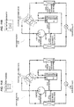
- a heat pump system 200 constituting a car air conditioner or the like includes an accumulator 250 in addition to a compressor 210, an outdoor heat exchanger 220, an indoor heat exchanger 230, an expansion valve 260, a four-way switching valve 240, and the like as in an example illustrated in Fig. 11 .
- a cooling operation and a heating operation are switched (a passage is switched) by the four-way switching valve 240.
- a refrigerant is circulated in a cycle illustrated in Fig. 11A .
- the outdoor heat exchanger 220 serves as a condenser and the indoor heat exchanger 230 serves as an evaporator.
- a refrigerant is circulated in a cycle illustrated in Fig. 11B .
- the outdoor heat exchanger 220 serves as the evaporator and the indoor heat exchanger 230 serves as the condenser.
- a low-temperature and low-pressure gas-liquid refrigerant is introduced from the evaporator (the indoor heat exchanger 230 or the outdoor heat exchanger 220) into the accumulator 250 through the four-way switching valve 240.
- Patent Document 1 discloses an accumulator including: a bottomed cylindrical tank of which an upper surface opening is air-tightly closed by a lid member provided with an inflow port and an outflow port, a gas-liquid separation body which has a hat shape or an inverse thin bowl shape and has a diameter smaller than the inner diameter of the tank, an outflow pipe which has a double pipe structure provided with an inner pipe and an outer pipe and has an upper end connected to the outflow port so as to be suspended, and a strainer which is provided in the vicinity of a bottom portion of the outflow pipe (the outer pipe thereof) and traps and removes the foreign material included in the liquid phase refrigerant and the oil (the refrigerator oil) mixed with the refrigerant.
- the refrigerant which is introduced into the accumulator 250 collides with the gas-liquid separation body so as to be diffused radially and separated into a liquid phase refrigerant and a gas phase refrigerant, the liquid phase refrigerant (including oil) flows downward along the inner peripheral surface of the tank so as to be accumulated in the lower portion of the tank, and the gas phase refrigerant flows downward in the space (the downward gas phase refrigerant flowing passage) formed between the outer pipe and the inner pipe of the outflow pipe and moves upward in the space inside the inner pipe so as to be suctioned to the suction side of the compressor 210. In this way, the refrigerant is circulated.
- the oil which is accumulated in the lower portion of the tank along with the liquid phase refrigerant moves toward the tank bottom portion by a difference in specific weight or property with respect to the liquid phase refrigerant, is suctioned to the gas phase refrigerant suctioned to the suction side of the compressor through the outflow pipe, and is returned to the suction side of the compressor along with the gas phase refrigerant while sequentially passing through the strainer (the mesh filter thereof), the oil returning hole formed in the bottom portion of the outflow pipe (the outer pipe), and the space inside the inner pipe of the outflow pipe. In this way, the oil can be circulated. When the oil passes through the mesh filter, a foreign material such as sludge is trapped and the foreign material is removed from the circulated refrigerant (including oil).
- Patent Document 1 JP 2014-70869 A
- the invention is made in view of the above-described circumstances and an object thereof is to provide an accumulator capable of trapping and removing a foreign material mixed with a liquid phase refrigerant even when the liquid phase refrigerant flows into an outflow pipe and hence decreasing the amount of the foreign material in the circulated refrigerant without causing an increase in size.
- an accumulator includes: a tank provided with an inflow port and an outflow port; an outflow pipe having a double pipe structure including an inner pipe connected to the outflow port so as to be dropped inside the tank and an outer pipe disposed on the outer periphery of the inner pipe; and a strainer provided in the vicinity of a lower end of the outflow pipe and including a mesh filter, in which the mesh filter is disposed between a space formed between the inner pipe and the outer pipe and a space inside the inner pipe and a side portion or a bottom portion of the outer pipe or a casing of the strainer is provided with a communication hole causing the space formed between the inner pipe and the outer pipe to communicate with a lower space of the tank.
- the casing of the strainer includes a cylindrical body portion to which an outer end of the mesh filter is connected and a bottom plate portion which is provided in a lower end of the body portion and has a diameter larger than the body portion, a lower end of the inner pipe is connected to an upper portion of the body portion, a lower end of the outer pipe is connected to an outer periphery of the bottom plate portion, and the communication hole is formed between the outer pipe and the body portion in the bottom plate portion.
- the casing of the strainer further includes a base portion or a support column portion which lifts the bottom plate portion from a tank bottom portion.
- the casing of the strainer includes a cylindrical body portion to which an outer end of the mesh filter is connected and a bottom plate portion which is provided in a lower end of the body portion and has a diameter larger than the body portion, a lower end of the inner pipe is connected to an upper portion of the body portion, a lower end of the outer pipe is connected to an outer periphery of the bottom plate portion, and the communication hole is formed at a side portion of the outer pipe.
- the lower end of the outer pipe is placed on the tank bottom portion.
- a second mesh filter is disposed so as to cover the communication hole forming portion from the outside.
- the accumulator since it is possible to trap and remove the foreign material mixed with the liquid phase refrigerant flowing from the upper portion of the outflow pipe into the space formed between the inner pipe and the output pipe in addition to the foreign material mixed with the liquid phase refrigerant including oil accumulated in the lower space of the tank by the specific strainer provided in the vicinity of the lower end of the outflow pipe, it is possible to effectively decrease the amount of the foreign material in the circulated refrigerant without causing an increase in size (particularly, overall height) of the accumulator. As a result, it is possible to reliably prevent the operation error and the malfunction of each of devices (the compressor, the four-way switching valve, the expansion valve, and the like) constituting the heat pump system.
- devices the compressor, the four-way switching valve, the expansion valve, and the like
- the second mesh filter is disposed so as to cover the communication hole forming portion from the outside, it is possible to trap and remove the foreign material mixed with the liquid phase refrigerant including oil accumulated in the lower space of the tank. Thus, it is possible to obtain an effect in which the blockage of the communication hole can be reliably prevented.
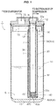
- Fig. 1 is a partially cutaway front view illustrating a first embodiment of an accumulator according to the invention and Fig. 3 is an enlarged half cross-sectional view illustrating a periphery of a strainer of the accumulator of the first embodiment.
- An accumulator 1 of the first embodiment illustrated in the drawing is used as an accumulator 250 of a heat pump system 200 of, for example, a car air conditioner of an electric vehicle as illustrated in Fig. 11 and includes a bottomed cylindrical tank 10 formed of metal such as stainless steel or aluminum alloy.
- a metallic lid member 12 an upper surface opening of the tank 10 is air-tightly closed by a metallic lid member 12.
- the accumulator 1 of the embodiment is disposed, for example, in the vertical direction. That is, the accumulator is installed so that the lid member 12 faces the upper (sky) side and the bottom portion of the tank 10 faces the lower (earth) side.
- the lid member 12 is provided with an inflow port 15 and a stepped outflow port 16 side by side.
- a gas-liquid separation body 18 having a hat shape or an inverse thin bowl shape and having a diameter smaller than the inner diameter of the tank 10 is disposed at the lower side of the lid member 12, an outflow pipe 30 is connected to the outflow port 16, and a strainer 40 is provided in the vicinity of the lower end of the outflow pipe 30.
- the outflow pipe 30 is configured as a double pipe structure which includes an inner pipe 31 formed of synthetic resin and an outer pipe 32 formed of metal and disposed on the outer periphery of the inner pipe 31.
- the inner pipe 31 includes upper and lower thin portions 31 a and 31 b each of which is formed in a step shape so that the upper end has a large diameter for the convenience or the like when the accumulator 1 is assembled (when the inner pipe 31 is press-fixed).
- the upper thin portion 31a is fitted and fixed into the stepped lower portion of the outflow port 16 so as to be suspended and the lower thin portion 31 b is fitted and fixed into an inner peripheral stepped upper portion 42a of a body portion 42A of a casing 42 of the strainer 40 to be described later through press-inserting or the like.
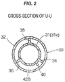
- a plurality of (in an example illustrated in the drawing, three) plate-shaped ribs 36 is provided at the same angular interval so as to protrude outward in the radial direction in a thick portion 31c excluding the upper and lower thin portions 31 a and 31 b of the inner pipe 31 as the cross-section illustrated in Fig. 2 and the outer pipe 32 is inserted and fixed to the outside of the plate-shaped rib 36 through press-fitting.
- the upper end of the outer pipe 32 is positioned in the vicinity of the upper end of the thick portion 31c of the inner pipe 31 and the upper portion of the plate-shaped rib 36 is provided so as to extend upward in relation to the thick portion 31 c.
- the upper thin portion 31a of the inner pipe 31 passes through a passage hole 19 provided in the gas-liquid separation body 18 and passes through the stepped lower portion of the outflow port 16 while being slightly narrowed by the elasticity thereof so that the upper thin portion 31 a is fitted and fixed into the stepped lower portion of the outflow port 16 through press-fitting. Accordingly, the gas-liquid separation body 18 is held and fixed so as to be sandwiched between the upper end surface of the plate-shaped rib 36 and the lower end surface of the lid member 12.
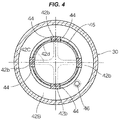
- the strainer 40 includes a flange-shaped portion attached bottomed cylindrical casing 42 which is formed of synthetic resin and a cylindrical mesh filter 45 which is integrated with the casing 42 by insert-molding.
- the mesh filter 45 is made of, for example, a wire net or a synthetic mesh.
- the casing 42 includes a cylindrical body portion 42A, a circular bottom plate portion 42B which has a diameter lager than the body portion 42A while the thin lower end of the outer pipe 32 is fixed by caulking or the like, and a cross-shaped base portion 42C which is used to lift the bottom plate portion 42B to a predetermined height from a tank bottom portion 13 while protruding downward toward the center side of the lower surface of the bottom plate portion 42B.
- the cylindrical body portion 42A includes the inner peripheral stepped upper portion 42a to which the lower thin portion 31 b of the inner pipe 31 is fitted and fixed, four column-shaped portions 42b which are uprightly formed at the same angular interval between the upper portion 42a and the bottom plate portion 42B, and circular band-shaped mesh end embedded portions 42d and 42d each of which has a predetermined thickness and a predetermined band width while including the upper and lower ends of the column-shaped portion 42b.
- the upper and lower ends of the mesh filter 45 made of the wire net or the like are integrated with the upper and lower mesh end embedded portions 42d and 42d so as to be sealed during the insert-molding process and the portion of the column-shaped portion 42b in the mesh filter 45 is also integrated with the column-shaped portion 42b so as to be sealed during the insert-molding process.
- four windows 44 each having a rectangular shape in the side view are defined by four column-shaped portions 42b and the upper and lower mesh end embedded portions 42d and 42d and the mesh filter 45 is stretched on each window 44.
- the mesh filter 45 is disposed between the space (the downward gas phase refrigerant flowing passage) J formed between the inner pipe 31 and the outer pipe 32 and the space I formed inside the inner pipe.
- a communication hole 46 which causes the space J formed between the inner pipe 31 and the outer pipe 32 to communicate with the lower space S of the tank 10 is formed between the outer pipe 32 and the body portion 42A of the bottom plate portion 42B of the strainer 40.
- the communication hole 46 corresponds to the oil returning hole of the accumulator of the related art and herein the hole diameter is set to about, for example, 1 mm.
- a low-temperature and low-pressure gas-liquid-phase refrigerant is introduced from the evaporator into the tank 10 through the inflow port 15, the introduced refrigerant collides with the gas-liquid separation body 18 so as to be diffused radially and separated into the liquid phase refrigerant and the gas phase refrigerant, the liquid phase refrigerant (including oil) flows downward along the inner peripheral surface of the tank 10 so as to be accumulated into the lower space S of the tank 10, and the gas phase refrigerant is suctioned to the suction side of the compressor 210 while sequentially passing through the space J formed between the inner pipe 31 and the outer pipe 32 of the outflow pipe 30, the mesh filter 45 of the strainer 40, and the space I inside the inner pipe. In this way, the refrigerant can be circulated.
- the oil which is accumulated in the lower space S of the tank 10 along with the liquid phase refrigerant moves toward the bottom portion 13 of the tank 10 by a difference in specific weight or property with respect to the liquid phase refrigerant, is suctioned to the gas phase refrigerant suctioned to the suction side of the compressor through the outflow pipe 30, and is returned to the suction side of the compressor along with the gas phase refrigerant while sequentially passing through the communication hole 46 provided in the bottom plate portion 42B, the mesh filter 45 of the strainer 40, and the space I inside the inner pipe. In this way, the oil can be circulated. When the oil passes through the mesh filter 45, a foreign material such as sludge is trapped and the foreign material is removed from the circulated refrigerant (including oil).
- the liquid phase refrigerant can be circulated while being suctioned to the suction side of the compressor 210 along with the gas phase refrigerant while sequentially passing through the space J, the mesh filter 45 of the strainer 40, and the space I inside the inner pipe. For that reason, even when a foreign material is mixed with the liquid phase refrigerant flowing into the space J, the foreign material is trapped when passing through the mesh filter 45 and is removed from the circulated refrigerant (including oil).
- the accumulator 1 of the embodiment since it is possible to trap and remove the foreign material which is mixed with the liquid phase refrigerant flowing from the upper portion of the outflow pipe 30 into the space J formed between the inner pipe 31 and the outer pipe 32 in addition to the foreign material mixed with the liquid phase refrigerant including oil accumulated in the lower space S of the tank 10 by the strainer 40 provided in the vicinity of the lower end of the outflow pipe 30, it is possible to effectively decrease the amount of the foreign material in the circulated refrigerant without increasing the size (particularly, the overall height) of the accumulator. As a result, it is possible to reliably prevent the operation error and the malfunction of each of devices (the compressor, the four-way switching valve, the expansion valve, and the like) constituting the heat pump system.
- devices the compressor, the four-way switching valve, the expansion valve, and the like
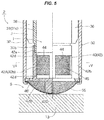
- Fig. 5 is an enlarged half cross-sectional view illustrating a main part of a periphery of a strainer of an accumulator 2 of a second embodiment
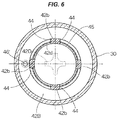
- Fig. 6 is a cross-sectional view taken along an arrow V-V of Fig. 5.
- Figs. 5 and 6 correspond to Figs. 3 and 4 illustrating a main part of the accumulator 1 of the first embodiment.
- a common reference numeral or a related reference numeral (attached with ""') is given to a part corresponding to the part of the accumulator 1 of the first embodiment.
- the configuration of the upper portion (not illustrated) of each of accumulators 2, 3, and 4 of the second embodiment and the third and fourth embodiments described below is basically the same as that of the accumulator 1 of the first embodiment.
- the mesh filter 45 is disposed between the space J formed between the inner pipe 31 and the outer pipe 32 and the space I inside the inner pipe and a communication hole 46' causing the space J formed between the inner pipe 31 and the outer pipe 32 to communicate with the lower space S of the tank 10 is formed between the outer pipe 32 and the body portion 42A of the bottom plate portion 42B of the strainer 40 as in the first embodiment.
- a second mesh filter 55 (different from the mesh filter 45) is disposed so as to cover the entire lower surface of the bottom plate portion 42C.
- the mesh filter 55 is used as the strainer of the accumulator of the related art and is formed in a spherical crown shape of, for example, the same material (metal or synthetic resin) as the mesh filter 45 of the strainer 40.
- a cross-shaped support column portion 42D (smaller than the base portion 42C of the first embodiment) which lifts the bottom plate portion 42B keeping the shape of the mesh filter 55 is provided at the center of the lower surface of the bottom plate portion 42C so as to protrude downward.
- the outer peripheral end of the mesh filter 55 and the outer peripheral end of the bottom plate portion 42B are simultaneously fastened and fixed to the thin lower end of the outer pipe 32 through caulking.
- the outer peripheral ends thereof are integrated with each other in advance by welding or adhering.
- the outer peripheral ends thereof are integrated with each other in advance by welding (spot welding). Accordingly, it is possible to easily perform such caulking at the thin lower end of the outer pipe 32.
- the mesh filter 55 and the bottom plate portion 42B may be integrally molded with each other in advance.
- one of the mesh filter 55 and the bottom plate portion 42B is formed of metal and the other thereof is formed of synthetic resin
- the mesh filter and the bottom plate portion can be integrated with each other through insert-molding or the like.
- the lower end (the top portion) of the mesh filter 55 is fixed to the outer pipe 32 while contacting the tank bottom portion 13 or being slightly separated from the tank bottom portion 13, but may be fixed to the tank bottom portion 13 through press-fitting.
- the liquid phase refrigerant including oil near the tank bottom portion 13 is suctioned to the gas phase refrigerant suctioned to the suction side of the compressor through the outflow pipe 30.
- a foreign material included in the liquid phase refrigerant is first trapped and removed by the second mesh filter 55.
- the liquid phase refrigerant is returned to the suction side of the compressor along with the gas phase refrigerant while sequentially passing through the communication hole 46' provided in the bottom plate portion 42B, the mesh filter 45 of the strainer 40, and the space I inside the inner pipe. In this way, the liquid phase refrigerant can be circulated.
- the second mesh filter 55 is disposed in this way, the foreign material mixed with the liquid phase refrigerant including oil accumulated in the lower space S of the tank 10 can be trapped and removed. Thus, it is possible to obtain an effect in which the blockage of the communication hole 46' can be reliably prevented in addition to the same operation and effect as the accumulator 1 of the first embodiment.
- Fig. 7 is an enlarged half cross-sectional view illustrating a main part of a periphery of a strainer of an accumulator 3 of a third embodiment
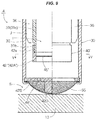
- Fig. 8 is a cross-sectional view taken along an arrow V-V of Fig. 7.
- Figs. 7 and 8 correspond to Figs. 3 and 4 illustrating a main part of the accumulator 1 of the first embodiment.
- a common reference numeral or a related reference numeral (attached with """ is given to a part corresponding to the part of the accumulator 1 of the first embodiment.
- the mesh filter 45 is disposed between the space J formed between the inner pipe 31 and the outer pipe 32 and the space I inside the inner pipe as in the first embodiment, but the communication hole forming position is different from that of the first embodiment.
- a communication hole 46" causing the space J formed between the inner pipe 31 and the outer pipe 32 to communicate with the lower space S of the tank 10 is formed at the side portion near the lower end of the outer pipe 32.
- the base portion 42C existing in the first embodiment is not provided and the thin lower end (the caulking portion) of the outer pipe 32 is fixed while contacting the tank bottom portion 13 or slightly separated from the tank bottom portion 13.
- the thin lower end (the caulking portion) of the outer pipe 32 may be disposed and fixed to the tank bottom portion 13 through press-fitting.
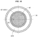
- Fig. 9 is an enlarged half cross-sectional view illustrating a main part of a periphery of a strainer of an accumulator 4 of a fourth embodiment and Fig. 10 is a cross-sectional view taken along an arrow V-V of Fig. 9.
- Figs. 9 and 10 correspond to Figs. 5 and 6 illustrating a main part of the accumulator 2 of the second embodiment.
- a common reference numeral or a related reference numeral (attached with ""') is given to a part corresponding to the part of the accumulator 2 of the second embodiment.
- a strainer 40' of the fourth embodiment includes a casing 42' which has a short cylindrical shape or a cylindrical frame shape and a disk-shaped mesh filter 45' which is integrated with the casing 42' through insert-molding.
- the casing 42' includes the inner peripheral stepped upper portion 42a into which the lower thin portion 31 b of the inner pipe 31 is fitted and fixed and a body portion 42A' into which the outer peripheral end of the disk-shaped mesh filter 45' is buried and sealed during the insert-molding process.
- a bottom structure including the second mesh filter 55 and the bottom plate portion 42B having the support column portion 42D protruding therefrom and having the communication hole 46' formed at a position slightly close to the center basically similar to that of the strainer 40 of the second embodiment is assembled to the lower end of the outer pipe 32.
- the outer peripheral end of the mesh filter 55 and the outer peripheral end of the bottom plate portion 42B are simultaneously fixed to the thin lower end of the outer pipe 32 through caulking.
- the outer pipe 32 may be integrally molded with the bottom plate portion 42B (as the bottomed outer pipe) by synthetic resin. In that case, the communication hole 46' is formed at the bottom portion of the bottomed outer pipe 32.
- the mesh filter 55 and the bottom plate portion 42B may be formed of the same material (metal or synthetic resin) or may be formed of different materials.
- the outer peripheral ends thereof are integrated with each other in advance by welding or adhering.
- the outer peripheral ends thereof are integrated with each other in advance by welding (spot welding). Accordingly, it is possible to easily perform such caulking at the thin lower end of the outer pipe 32.
- the mesh filter 55 and the bottom plate portion 42B may be integrally molded with each other in advance.
- one of the mesh filter 55 and the bottom plate portion 42B is formed of metal and the other thereof is formed of synthetic resin
- the mesh filter and the bottom plate portion may be integrated with each other through insert-molding or the like.
- the mesh filter 45' is disposed between the space J formed between the inner pipe 31 and the outer pipe 32 and the space I inside the inner pipe and the communication hole 46' causing the space J formed between the inner pipe 31 and the outer pipe 32 to communicate with the lower space S of the tank 10 is formed in the bottom plate portion 42B of the strainer 40' as in the second embodiment.
- the second mesh filter 55 is disposed so as to cover the communication hole 46' from the outside.
- the liquid phase refrigerant including oil near the tank bottom portion 13 is suctioned to the gas phase refrigerant suctioned to the suction side of the compressor through the outflow pipe 30.
- a foreign material included in the liquid phase refrigerant is trapped and removed by the second mesh filter 55.
- the liquid phase refrigerant is returned to the suction side of the compressor along with the gas phase refrigerant while sequentially passing through the communication hole 46' provided in the bottom plate portion 42B, the disk-shaped mesh filter 45', and the space I inside the inner pipe. In this way, the liquid phase refrigerant can be circulated.
- the second mesh filter 55 a foreign material such as sludge is trapped, and the foreign material is removed from the circulated refrigerant (including oil).
- the second mesh filter 55 is disposed in this way, it is possible to trap and remove the foreign material mixed with the liquid phase refrigerant including the oil accumulated in the lower space S of the tank 10 and hence to reliably prevent the blockage of the communication hole 46'.
- the liquid phase refrigerant can be circulated while being suctioned to the suction side of the compressor 210 along with the gas phase refrigerant while sequentially passing through the space J, the disk-shaped mesh filter 45', and the space I inside the inner pipe. For that reason, even when a foreign material is mixed with the liquid phase refrigerant flowing into the space J, the foreign material is trapped when passing through the disk-shaped mesh filter 45' and is removed from the circulated refrigerant (including oil).
Landscapes
- Engineering & Computer Science (AREA)
- Chemical & Material Sciences (AREA)
- Analytical Chemistry (AREA)
- Power Engineering (AREA)
- Physics & Mathematics (AREA)
- Mechanical Engineering (AREA)
- Thermal Sciences (AREA)
- General Engineering & Computer Science (AREA)
- Applications Or Details Of Rotary Compressors (AREA)
- Supply Devices, Intensifiers, Converters, And Telemotors (AREA)
- Filtering Of Dispersed Particles In Gases (AREA)
- Compressor (AREA)
Abstract
Description
- The present invention relates to an accumulator (a gas-liquid separator) that is used in a heat pump type refrigeration cycle (hereinafter, referred to as a heat pump system) such as a car air conditioner, a room air conditioner, and a refrigerator.
- In general, a
heat pump system 200 constituting a car air conditioner or the like includes anaccumulator 250 in addition to a compressor 210, anoutdoor heat exchanger 220, anindoor heat exchanger 230, anexpansion valve 260, a four-way switching valve 240, and the like as in an example illustrated inFig. 11 . - In such a
system 200, a cooling operation and a heating operation are switched (a passage is switched) by the four-way switching valve 240. In the cooling operation, a refrigerant is circulated in a cycle illustrated inFig. 11A . At this time, theoutdoor heat exchanger 220 serves as a condenser and theindoor heat exchanger 230 serves as an evaporator. Meanwhile, in the heating operation, a refrigerant is circulated in a cycle illustrated inFig. 11B . At this time, theoutdoor heat exchanger 220 serves as the evaporator and theindoor heat exchanger 230 serves as the condenser. In any operation mode, a low-temperature and low-pressure gas-liquid refrigerant is introduced from the evaporator (theindoor heat exchanger 230 or the outdoor heat exchanger 220) into theaccumulator 250 through the four-way switching valve 240. - As the
accumulator 250, for example,Patent Document 1 discloses an accumulator including: a bottomed cylindrical tank of which an upper surface opening is air-tightly closed by a lid member provided with an inflow port and an outflow port, a gas-liquid separation body which has a hat shape or an inverse thin bowl shape and has a diameter smaller than the inner diameter of the tank, an outflow pipe which has a double pipe structure provided with an inner pipe and an outer pipe and has an upper end connected to the outflow port so as to be suspended, and a strainer which is provided in the vicinity of a bottom portion of the outflow pipe (the outer pipe thereof) and traps and removes the foreign material included in the liquid phase refrigerant and the oil (the refrigerator oil) mixed with the refrigerant. - The refrigerant which is introduced into the
accumulator 250 collides with the gas-liquid separation body so as to be diffused radially and separated into a liquid phase refrigerant and a gas phase refrigerant, the liquid phase refrigerant (including oil) flows downward along the inner peripheral surface of the tank so as to be accumulated in the lower portion of the tank, and the gas phase refrigerant flows downward in the space (the downward gas phase refrigerant flowing passage) formed between the outer pipe and the inner pipe of the outflow pipe and moves upward in the space inside the inner pipe so as to be suctioned to the suction side of the compressor 210. In this way, the refrigerant is circulated. - Further, the oil which is accumulated in the lower portion of the tank along with the liquid phase refrigerant moves toward the tank bottom portion by a difference in specific weight or property with respect to the liquid phase refrigerant, is suctioned to the gas phase refrigerant suctioned to the suction side of the compressor through the outflow pipe, and is returned to the suction side of the compressor along with the gas phase refrigerant while sequentially passing through the strainer (the mesh filter thereof), the oil returning hole formed in the bottom portion of the outflow pipe (the outer pipe), and the space inside the inner pipe of the outflow pipe. In this way, the oil can be circulated. When the oil passes through the mesh filter, a foreign material such as sludge is trapped and the foreign material is removed from the circulated refrigerant (including oil).
- Since the foreign material is trapped and removed by the strainer in this way, it is possible to prevent the blockage and the like caused by the foreign material in an orifice (a small hole) or a gap formed between sliding members of the devices (the compressor, the four-way switching valve, the expansion valve, and the like) constituting the system and hence to prevent the operation error and the malfunction.
- Patent Document 1:
JP 2014-70869 A - Incidentally, in the above-described accumulator, there is a case in which the liquid phase refrigerant directly flows from the upper portion of the outflow pipe into the space (the downward gas phase refrigerant flowing passage) formed between the inner pipe and the outer pipe due to a certain reason. In this case, there is a concern that the foreign material may be mixed with the circulated refrigerant.
- There is a tendency that the flow (the amount and the frequency) of the liquid phase refrigerant toward the outflow pipe increases as a difference in height between the liquid level position of the liquid phase refrigerant and the upper end (opening) position of the outer pipe decreases. Thus, for example, when the overall height of the outflow pipe or the tank is increased so as to increase the upper end (opening) position of the outer pipe, the flow (the amount and the frequency) of the liquid phase refrigerant toward the outflow pipe can be decreased. However, in that case, a problem arises in that the size (particularly, the overall height) of the accumulator increases.
- The invention is made in view of the above-described circumstances and an object thereof is to provide an accumulator capable of trapping and removing a foreign material mixed with a liquid phase refrigerant even when the liquid phase refrigerant flows into an outflow pipe and hence decreasing the amount of the foreign material in the circulated refrigerant without causing an increase in size.
- In order to attain the above-described object, an accumulator according to the invention includes: a tank provided with an inflow port and an outflow port; an outflow pipe having a double pipe structure including an inner pipe connected to the outflow port so as to be dropped inside the tank and an outer pipe disposed on the outer periphery of the inner pipe; and a strainer provided in the vicinity of a lower end of the outflow pipe and including a mesh filter, in which the mesh filter is disposed between a space formed between the inner pipe and the outer pipe and a space inside the inner pipe and a side portion or a bottom portion of the outer pipe or a casing of the strainer is provided with a communication hole causing the space formed between the inner pipe and the outer pipe to communicate with a lower space of the tank.
- In this case, preferably, the casing of the strainer includes a cylindrical body portion to which an outer end of the mesh filter is connected and a bottom plate portion which is provided in a lower end of the body portion and has a diameter larger than the body portion, a lower end of the inner pipe is connected to an upper portion of the body portion, a lower end of the outer pipe is connected to an outer periphery of the bottom plate portion, and the communication hole is formed between the outer pipe and the body portion in the bottom plate portion.
- As a more preferable aspect, the casing of the strainer further includes a base portion or a support column portion which lifts the bottom plate portion from a tank bottom portion.
- Further, preferably, the casing of the strainer includes a cylindrical body portion to which an outer end of the mesh filter is connected and a bottom plate portion which is provided in a lower end of the body portion and has a diameter larger than the body portion, a lower end of the inner pipe is connected to an upper portion of the body portion, a lower end of the outer pipe is connected to an outer periphery of the bottom plate portion, and the communication hole is formed at a side portion of the outer pipe.
- As a still more preferable aspect, the lower end of the outer pipe is placed on the tank bottom portion.
- As the other preferable aspect, a second mesh filter is disposed so as to cover the communication hole forming portion from the outside.
- In the accumulator according to the aspect of the invention, since it is possible to trap and remove the foreign material mixed with the liquid phase refrigerant flowing from the upper portion of the outflow pipe into the space formed between the inner pipe and the output pipe in addition to the foreign material mixed with the liquid phase refrigerant including oil accumulated in the lower space of the tank by the specific strainer provided in the vicinity of the lower end of the outflow pipe, it is possible to effectively decrease the amount of the foreign material in the circulated refrigerant without causing an increase in size (particularly, overall height) of the accumulator. As a result, it is possible to reliably prevent the operation error and the malfunction of each of devices (the compressor, the four-way switching valve, the expansion valve, and the like) constituting the heat pump system.
- Further, since the second mesh filter is disposed so as to cover the communication hole forming portion from the outside, it is possible to trap and remove the foreign material mixed with the liquid phase refrigerant including oil accumulated in the lower space of the tank. Thus, it is possible to obtain an effect in which the blockage of the communication hole can be reliably prevented.
-
-
Fig. 1 is a partially cutaway front view illustrating a first embodiment of an accumulator according to the invention; -
Fig. 2 is an enlarged cross-sectional view taken along an arrow U-U ofFig. 1 ; -
Fig. 3 is an enlarged half cross-sectional view illustrating a main part of a strainer of the accumulator of the first embodiment; -
Fig. 4 is a cross-sectional view taken along an arrow V-V ofFig. 3 ; -
Fig. 5 is an enlarged half cross-sectional view illustrating a main part of a periphery of a strainer of an accumulator of a second embodiment; -
Fig. 6 is a cross-sectional view taken along an arrow V-V ofFig. 5 ; -
Fig. 7 is an enlarged half cross-sectional view illustrating a main part of a periphery of a strainer of an accumulator of a third embodiment; -
Fig. 8 is a cross-sectional view taken along an arrow V-V ofFig. 7 ; -
Fig. 9 is an enlarged half cross-sectional view illustrating a main part of a periphery of a strainer of an accumulator of a fourth embodiment; -
Fig. 10 is a cross-sectional view taken along an arrow V-V ofFig. 9 ; and -
Fig. 11 illustrates an example of a heat pump system, whereFig. 11A is a schematic configuration diagram illustrating a flow (a cycle) of a refrigerant in a cooling operation andFig. 11B is a schematic configuration diagram illustrating a flow (a cycle) of a refrigerant in a heating operation. - Hereinafter, embodiments of the invention will be described with reference to the drawings.
-
Fig. 1 is a partially cutaway front view illustrating a first embodiment of an accumulator according to the invention andFig. 3 is an enlarged half cross-sectional view illustrating a periphery of a strainer of the accumulator of the first embodiment. - An
accumulator 1 of the first embodiment illustrated in the drawing is used as anaccumulator 250 of aheat pump system 200 of, for example, a car air conditioner of an electric vehicle as illustrated inFig. 11 and includes a bottomedcylindrical tank 10 formed of metal such as stainless steel or aluminum alloy. Here, an upper surface opening of thetank 10 is air-tightly closed by ametallic lid member 12. In addition, theaccumulator 1 of the embodiment is disposed, for example, in the vertical direction. That is, the accumulator is installed so that thelid member 12 faces the upper (sky) side and the bottom portion of thetank 10 faces the lower (earth) side. - The
lid member 12 is provided with aninflow port 15 and astepped outflow port 16 side by side. Here, a gas-liquid separation body 18 having a hat shape or an inverse thin bowl shape and having a diameter smaller than the inner diameter of thetank 10 is disposed at the lower side of thelid member 12, anoutflow pipe 30 is connected to theoutflow port 16, and astrainer 40 is provided in the vicinity of the lower end of theoutflow pipe 30. - The
outflow pipe 30 is configured as a double pipe structure which includes aninner pipe 31 formed of synthetic resin and anouter pipe 32 formed of metal and disposed on the outer periphery of theinner pipe 31. - The
inner pipe 31 includes upper and lowerthin portions accumulator 1 is assembled (when theinner pipe 31 is press-fixed). Here, the upperthin portion 31a is fitted and fixed into the stepped lower portion of theoutflow port 16 so as to be suspended and the lowerthin portion 31 b is fitted and fixed into an inner peripheral steppedupper portion 42a of abody portion 42A of acasing 42 of thestrainer 40 to be described later through press-inserting or the like. - A plurality of (in an example illustrated in the drawing, three) plate-shaped
ribs 36 is provided at the same angular interval so as to protrude outward in the radial direction in athick portion 31c excluding the upper and lowerthin portions inner pipe 31 as the cross-section illustrated inFig. 2 and theouter pipe 32 is inserted and fixed to the outside of the plate-shapedrib 36 through press-fitting. The upper end of theouter pipe 32 is positioned in the vicinity of the upper end of thethick portion 31c of theinner pipe 31 and the upper portion of the plate-shapedrib 36 is provided so as to extend upward in relation to thethick portion 31 c. - When the gas-
liquid separation body 18 and theinner pipe 31 are assembled to thelid member 12, the upperthin portion 31a of theinner pipe 31 passes through apassage hole 19 provided in the gas-liquid separation body 18 and passes through the stepped lower portion of theoutflow port 16 while being slightly narrowed by the elasticity thereof so that the upperthin portion 31 a is fitted and fixed into the stepped lower portion of theoutflow port 16 through press-fitting. Accordingly, the gas-liquid separation body 18 is held and fixed so as to be sandwiched between the upper end surface of the plate-shapedrib 36 and the lower end surface of thelid member 12. - Meanwhile, as understood by referring to
Figs. 3 and4 , thestrainer 40 includes a flange-shaped portion attached bottomedcylindrical casing 42 which is formed of synthetic resin and acylindrical mesh filter 45 which is integrated with thecasing 42 by insert-molding. Themesh filter 45 is made of, for example, a wire net or a synthetic mesh. - The
casing 42 includes acylindrical body portion 42A, a circularbottom plate portion 42B which has a diameter lager than thebody portion 42A while the thin lower end of theouter pipe 32 is fixed by caulking or the like, and across-shaped base portion 42C which is used to lift thebottom plate portion 42B to a predetermined height from atank bottom portion 13 while protruding downward toward the center side of the lower surface of thebottom plate portion 42B. - The
cylindrical body portion 42A includes the inner peripheral steppedupper portion 42a to which the lowerthin portion 31 b of theinner pipe 31 is fitted and fixed, four column-shapedportions 42b which are uprightly formed at the same angular interval between theupper portion 42a and thebottom plate portion 42B, and circular band-shaped mesh end embeddedportions portion 42b. The upper and lower ends of themesh filter 45 made of the wire net or the like are integrated with the upper and lower mesh end embeddedportions portion 42b in themesh filter 45 is also integrated with the column-shapedportion 42b so as to be sealed during the insert-molding process. In other words, fourwindows 44 each having a rectangular shape in the side view are defined by four column-shapedportions 42b and the upper and lower mesh end embeddedportions mesh filter 45 is stretched on eachwindow 44. - Thus, in the
accumulator 1 of the embodiment, themesh filter 45 is disposed between the space (the downward gas phase refrigerant flowing passage) J formed between theinner pipe 31 and theouter pipe 32 and the space I formed inside the inner pipe. - Then, a
communication hole 46 which causes the space J formed between theinner pipe 31 and theouter pipe 32 to communicate with the lower space S of thetank 10 is formed between theouter pipe 32 and thebody portion 42A of thebottom plate portion 42B of thestrainer 40. Thecommunication hole 46 corresponds to the oil returning hole of the accumulator of the related art and herein the hole diameter is set to about, for example, 1 mm. - In the
accumulator 1 with such a configuration, as in the related art, a low-temperature and low-pressure gas-liquid-phase refrigerant is introduced from the evaporator into thetank 10 through theinflow port 15, the introduced refrigerant collides with the gas-liquid separation body 18 so as to be diffused radially and separated into the liquid phase refrigerant and the gas phase refrigerant, the liquid phase refrigerant (including oil) flows downward along the inner peripheral surface of thetank 10 so as to be accumulated into the lower space S of thetank 10, and the gas phase refrigerant is suctioned to the suction side of the compressor 210 while sequentially passing through the space J formed between theinner pipe 31 and theouter pipe 32 of theoutflow pipe 30, themesh filter 45 of thestrainer 40, and the space I inside the inner pipe. In this way, the refrigerant can be circulated. - Further, the oil which is accumulated in the lower space S of the
tank 10 along with the liquid phase refrigerant moves toward thebottom portion 13 of thetank 10 by a difference in specific weight or property with respect to the liquid phase refrigerant, is suctioned to the gas phase refrigerant suctioned to the suction side of the compressor through theoutflow pipe 30, and is returned to the suction side of the compressor along with the gas phase refrigerant while sequentially passing through thecommunication hole 46 provided in thebottom plate portion 42B, themesh filter 45 of thestrainer 40, and the space I inside the inner pipe. In this way, the oil can be circulated. When the oil passes through themesh filter 45, a foreign material such as sludge is trapped and the foreign material is removed from the circulated refrigerant (including oil). - Meanwhile, even when the liquid phase refrigerant flows from the upper portion of the
outflow pipe 30 into the space J formed between theinner pipe 31 and theouter pipe 32 due to a certain reason, the liquid phase refrigerant can be circulated while being suctioned to the suction side of the compressor 210 along with the gas phase refrigerant while sequentially passing through the space J, themesh filter 45 of thestrainer 40, and the space I inside the inner pipe. For that reason, even when a foreign material is mixed with the liquid phase refrigerant flowing into the space J, the foreign material is trapped when passing through themesh filter 45 and is removed from the circulated refrigerant (including oil). - In this way, in the
accumulator 1 of the embodiment, since it is possible to trap and remove the foreign material which is mixed with the liquid phase refrigerant flowing from the upper portion of theoutflow pipe 30 into the space J formed between theinner pipe 31 and theouter pipe 32 in addition to the foreign material mixed with the liquid phase refrigerant including oil accumulated in the lower space S of thetank 10 by thestrainer 40 provided in the vicinity of the lower end of theoutflow pipe 30, it is possible to effectively decrease the amount of the foreign material in the circulated refrigerant without increasing the size (particularly, the overall height) of the accumulator. As a result, it is possible to reliably prevent the operation error and the malfunction of each of devices (the compressor, the four-way switching valve, the expansion valve, and the like) constituting the heat pump system. -
Fig. 5 is an enlarged half cross-sectional view illustrating a main part of a periphery of a strainer of anaccumulator 2 of a second embodiment andFig. 6 is a cross-sectional view taken along an arrow V-V ofFig. 5. Figs. 5 and6 correspond toFigs. 3 and4 illustrating a main part of theaccumulator 1 of the first embodiment. Then, inFigs. 5 and6 illustrating theaccumulator 2 of the second embodiment, a common reference numeral or a related reference numeral (attached with ""') is given to a part corresponding to the part of theaccumulator 1 of the first embodiment. Further, the configuration of the upper portion (not illustrated) of each ofaccumulators accumulator 1 of the first embodiment. - Hereinafter, a difference from the first embodiment will be mainly described.
- In the
accumulator 2 of the second embodiment illustrated in the drawing, themesh filter 45 is disposed between the space J formed between theinner pipe 31 and theouter pipe 32 and the space I inside the inner pipe and a communication hole 46' causing the space J formed between theinner pipe 31 and theouter pipe 32 to communicate with the lower space S of thetank 10 is formed between theouter pipe 32 and thebody portion 42A of thebottom plate portion 42B of thestrainer 40 as in the first embodiment. In addition, in the second embodiment, a second mesh filter 55 (different from the mesh filter 45) is disposed so as to cover the entire lower surface of thebottom plate portion 42C. - More specifically, the
mesh filter 55 is used as the strainer of the accumulator of the related art and is formed in a spherical crown shape of, for example, the same material (metal or synthetic resin) as themesh filter 45 of thestrainer 40. A cross-shapedsupport column portion 42D (smaller than thebase portion 42C of the first embodiment) which lifts thebottom plate portion 42B keeping the shape of themesh filter 55 is provided at the center of the lower surface of thebottom plate portion 42C so as to protrude downward. The outer peripheral end of themesh filter 55 and the outer peripheral end of thebottom plate portion 42B are simultaneously fastened and fixed to the thin lower end of theouter pipe 32 through caulking. - Further, when the
mesh filter 55 and thebottom plate portion 42B are formed of resin, the outer peripheral ends thereof are integrated with each other in advance by welding or adhering. Alternatively, when the mesh filter and the bottom plate portion are formed of metal, the outer peripheral ends thereof are integrated with each other in advance by welding (spot welding). Accordingly, it is possible to easily perform such caulking at the thin lower end of theouter pipe 32. - Of course, the
mesh filter 55 and thebottom plate portion 42B may be integrally molded with each other in advance. In this case, when one of themesh filter 55 and thebottom plate portion 42B is formed of metal and the other thereof is formed of synthetic resin, the mesh filter and the bottom plate portion can be integrated with each other through insert-molding or the like. - Further, the lower end (the top portion) of the
mesh filter 55 is fixed to theouter pipe 32 while contacting thetank bottom portion 13 or being slightly separated from thetank bottom portion 13, but may be fixed to thetank bottom portion 13 through press-fitting. - In the
accumulator 2 of the second embodiment with such a configuration, the liquid phase refrigerant including oil near thetank bottom portion 13 is suctioned to the gas phase refrigerant suctioned to the suction side of the compressor through theoutflow pipe 30. Here, a foreign material included in the liquid phase refrigerant is first trapped and removed by thesecond mesh filter 55. Then, the liquid phase refrigerant is returned to the suction side of the compressor along with the gas phase refrigerant while sequentially passing through the communication hole 46' provided in thebottom plate portion 42B, themesh filter 45 of thestrainer 40, and the space I inside the inner pipe. In this way, the liquid phase refrigerant can be circulated. - Since the
second mesh filter 55 is disposed in this way, the foreign material mixed with the liquid phase refrigerant including oil accumulated in the lower space S of thetank 10 can be trapped and removed. Thus, it is possible to obtain an effect in which the blockage of the communication hole 46' can be reliably prevented in addition to the same operation and effect as theaccumulator 1 of the first embodiment. -
Fig. 7 is an enlarged half cross-sectional view illustrating a main part of a periphery of a strainer of an accumulator 3 of a third embodiment andFig. 8 is a cross-sectional view taken along an arrow V-V ofFig. 7. Figs. 7 and8 correspond toFigs. 3 and4 illustrating a main part of theaccumulator 1 of the first embodiment. InFigs. 7 and8 illustrating the accumulator 3 of the third embodiment, a common reference numeral or a related reference numeral (attached with """) is given to a part corresponding to the part of theaccumulator 1 of the first embodiment. - Hereinafter, a different from the first embodiment will be mainly described.
- In the accumulator 3 of the third embodiment illustrated in the drawing, the
mesh filter 45 is disposed between the space J formed between theinner pipe 31 and theouter pipe 32 and the space I inside the inner pipe as in the first embodiment, but the communication hole forming position is different from that of the first embodiment. - That is, in the accumulator 3 of the embodiment, a
communication hole 46" causing the space J formed between theinner pipe 31 and theouter pipe 32 to communicate with the lower space S of thetank 10 is formed at the side portion near the lower end of theouter pipe 32. Thus, thebase portion 42C existing in the first embodiment is not provided and the thin lower end (the caulking portion) of theouter pipe 32 is fixed while contacting thetank bottom portion 13 or slightly separated from thetank bottom portion 13. However, the thin lower end (the caulking portion) of theouter pipe 32 may be disposed and fixed to thetank bottom portion 13 through press-fitting. - Even in the accumulator 3 of the third embodiment with such a configuration, it is possible to obtain the same operation and effect as the
accumulator 1 of the first embodiment. Additionally, in the accumulator 3 of the third embodiment, when the second mesh filter (the strainer) is disposed so as to cover at least thecommunication hole 46", it is possible to obtain an effect in which the blockage of thecommunication hole 46" can be reliably prevented as in the second embodiment. -
Fig. 9 is an enlarged half cross-sectional view illustrating a main part of a periphery of a strainer of anaccumulator 4 of a fourth embodiment andFig. 10 is a cross-sectional view taken along an arrow V-V ofFig. 9. Figs. 9 and10 correspond toFigs. 5 and6 illustrating a main part of theaccumulator 2 of the second embodiment. Here, inFigs. 9 and10 illustrating theaccumulator 4 of the fourth embodiment, a common reference numeral or a related reference numeral (attached with ""') is given to a part corresponding to the part of theaccumulator 2 of the second embodiment. - Hereinafter, a difference from the second embodiment will be mainly described.
- In the
accumulator 4 of the fourth embodiment illustrated in the drawing, the configurations of the strainer and the outer pipe are different from those of the second embodiment. That is, a strainer 40' of the fourth embodiment includes a casing 42' which has a short cylindrical shape or a cylindrical frame shape and a disk-shaped mesh filter 45' which is integrated with the casing 42' through insert-molding. Specifically, the casing 42' includes the inner peripheral steppedupper portion 42a into which the lowerthin portion 31 b of theinner pipe 31 is fitted and fixed and abody portion 42A' into which the outer peripheral end of the disk-shaped mesh filter 45' is buried and sealed during the insert-molding process. - Further, a bottom structure including the
second mesh filter 55 and thebottom plate portion 42B having thesupport column portion 42D protruding therefrom and having the communication hole 46' formed at a position slightly close to the center basically similar to that of thestrainer 40 of the second embodiment is assembled to the lower end of theouter pipe 32. Specifically, the outer peripheral end of themesh filter 55 and the outer peripheral end of thebottom plate portion 42B are simultaneously fixed to the thin lower end of theouter pipe 32 through caulking. Further, theouter pipe 32 may be integrally molded with thebottom plate portion 42B (as the bottomed outer pipe) by synthetic resin. In that case, the communication hole 46' is formed at the bottom portion of the bottomedouter pipe 32. - In addition, the
mesh filter 55 and thebottom plate portion 42B may be formed of the same material (metal or synthetic resin) or may be formed of different materials. - Further, when the
mesh filter 55 and thebottom plate portion 42B are formed of resin, the outer peripheral ends thereof are integrated with each other in advance by welding or adhering. Alternatively, when the mesh filter and the bottom plate portion are formed of metal, the outer peripheral ends thereof are integrated with each other in advance by welding (spot welding). Accordingly, it is possible to easily perform such caulking at the thin lower end of theouter pipe 32. - Of course, the
mesh filter 55 and thebottom plate portion 42B may be integrally molded with each other in advance. In this case, when one of themesh filter 55 and thebottom plate portion 42B is formed of metal and the other thereof is formed of synthetic resin, the mesh filter and the bottom plate portion may be integrated with each other through insert-molding or the like. - Thus, even in the
accumulator 4 of the fourth embodiment, the mesh filter 45' is disposed between the space J formed between theinner pipe 31 and theouter pipe 32 and the space I inside the inner pipe and the communication hole 46' causing the space J formed between theinner pipe 31 and theouter pipe 32 to communicate with the lower space S of thetank 10 is formed in thebottom plate portion 42B of the strainer 40' as in the second embodiment. Additionally, thesecond mesh filter 55 is disposed so as to cover the communication hole 46' from the outside. - Even in the
accumulator 4 of the fourth embodiment with such a configuration, the liquid phase refrigerant including oil near thetank bottom portion 13 is suctioned to the gas phase refrigerant suctioned to the suction side of the compressor through theoutflow pipe 30. Here, a foreign material included in the liquid phase refrigerant is trapped and removed by thesecond mesh filter 55. Then, the liquid phase refrigerant is returned to the suction side of the compressor along with the gas phase refrigerant while sequentially passing through the communication hole 46' provided in thebottom plate portion 42B, the disk-shaped mesh filter 45', and the space I inside the inner pipe. In this way, the liquid phase refrigerant can be circulated. When the refrigerant passes through thesecond mesh filter 55, a foreign material such as sludge is trapped, and the foreign material is removed from the circulated refrigerant (including oil). - Since the
second mesh filter 55 is disposed in this way, it is possible to trap and remove the foreign material mixed with the liquid phase refrigerant including the oil accumulated in the lower space S of thetank 10 and hence to reliably prevent the blockage of the communication hole 46'. - Meanwhile, even when the liquid phase refrigerant flows from the upper portion of the
outflow pipe 30 into the space J formed between theinner pipe 31 and theouter pipe 32 due to a certain reason, the liquid phase refrigerant can be circulated while being suctioned to the suction side of the compressor 210 along with the gas phase refrigerant while sequentially passing through the space J, the disk-shaped mesh filter 45', and the space I inside the inner pipe. For that reason, even when a foreign material is mixed with the liquid phase refrigerant flowing into the space J, the foreign material is trapped when passing through the disk-shaped mesh filter 45' and is removed from the circulated refrigerant (including oil). - Thus, it is possible to obtain the same effect as the first to third embodiments.
Claims (6)
- An accumulator comprising:a tank provided with an inflow port and an outflow port;an outflow pipe having a double pipe structure including an inner pipe connected to the outflow port so as to be dropped inside the tank and an outer pipe disposed on the outer periphery of the inner pipe; anda strainer provided in the vicinity of a lower end of the outflow pipe and including a mesh filter,wherein the mesh filter is disposed between a space formed between the inner pipe and the outer pipe and a space inside the inner pipe and a side portion or a bottom portion of the outer pipe or a casing of the strainer is provided with a communication hole causing the space formed between the inner pipe and the outer pipe to communicate with a lower space of the tank.
- The accumulator according to claim 1,
wherein the casing of the strainer includes a cylindrical body portion to which an outer end of the mesh filter is connected and a bottom plate portion which is provided in a lower end of the body portion and has a diameter larger than the body portion,
wherein a lower end of the inner pipe is connected to an upper portion of the body portion and a lower end of the outer pipe is connected to an outer periphery of the bottom plate portion, and
wherein the communication hole is formed between the outer pipe and the body portion in the bottom plate portion. - The accumulator according to claim 2,
wherein the casing of the strainer further includes a base portion or a support column portion which lifts the bottom plate portion from a tank bottom portion. - The accumulator according to claim 1,
wherein the casing of the strainer includes a cylindrical body portion to which an outer end of the mesh filter is connected and a bottom plate portion which is provided in a lower end of the body portion and has a diameter larger than the body portion,
wherein a lower end of the inner pipe is connected to an upper portion of the body portion and a lower end of the outer pipe is connected to an outer periphery of the bottom plate portion, and
wherein the communication hole is formed at a side portion of the outer pipe. - The accumulator according to claim 4,
wherein the lower end of the outer pipe is placed on a tank bottom portion. - The accumulator according to any one of claims 1 to 5,
wherein a second mesh filter is disposed so as to cover the communication hole forming portion from the outside.
Applications Claiming Priority (1)
| Application Number | Priority Date | Filing Date | Title |
|---|---|---|---|
| JP2015139578A JP6594685B2 (en) | 2015-07-13 | 2015-07-13 | accumulator |
Publications (3)
| Publication Number | Publication Date |
|---|---|
| EP3118543A2 true EP3118543A2 (en) | 2017-01-18 |
| EP3118543A3 EP3118543A3 (en) | 2017-03-01 |
| EP3118543B1 EP3118543B1 (en) | 2023-09-06 |
Family
ID=56116291
Family Applications (1)
| Application Number | Title | Priority Date | Filing Date |
|---|---|---|---|
| EP16173217.7A Active EP3118543B1 (en) | 2015-07-13 | 2016-06-07 | Accumulator |
Country Status (3)
| Country | Link |
|---|---|
| EP (1) | EP3118543B1 (en) |
| JP (1) | JP6594685B2 (en) |
| CN (1) | CN106352617B (en) |
Families Citing this family (3)
| Publication number | Priority date | Publication date | Assignee | Title |
|---|---|---|---|---|
| JP6815036B2 (en) * | 2017-12-01 | 2021-01-20 | 株式会社不二工機 | accumulator |
| WO2019181866A1 (en) * | 2018-03-23 | 2019-09-26 | カルソニックカンセイ株式会社 | Gas-liquid separator |
| JP7197404B2 (en) * | 2018-03-23 | 2022-12-27 | ハイリマレリジャパン株式会社 | gas-liquid separator |
Citations (1)
| Publication number | Priority date | Publication date | Assignee | Title |
|---|---|---|---|---|
| JP2014070869A (en) | 2012-10-02 | 2014-04-21 | Fuji Koki Corp | Accumulator |
Family Cites Families (13)
| Publication number | Priority date | Publication date | Assignee | Title |
|---|---|---|---|---|
| US5636525A (en) * | 1996-04-02 | 1997-06-10 | Multisorb Technologies, Inc. | Saddle type adsorbent unit |
| JP2000356439A (en) * | 1999-06-16 | 2000-12-26 | Denso Corp | accumulator |
| JP2002130871A (en) * | 2000-10-30 | 2002-05-09 | Denso Corp | accumulator |
| JP4180874B2 (en) * | 2002-10-11 | 2008-11-12 | 株式会社不二工機 | accumulator |
| JP4224372B2 (en) * | 2003-09-30 | 2009-02-12 | 株式会社不二工機 | accumulator |
| JP2008032270A (en) * | 2006-07-26 | 2008-02-14 | Denso Corp | accumulator |
| KR100784611B1 (en) * | 2006-08-18 | 2007-12-11 | 주식회사 두원공조 | Gas-liquid separator with internal heat exchanger of cooling system |
| JP2008215727A (en) * | 2007-03-05 | 2008-09-18 | Denso Corp | Refrigerant container and accumulator |
| JP5764372B2 (en) * | 2011-04-15 | 2015-08-19 | 株式会社不二工機 | accumulator |
| CN103712385B (en) * | 2012-10-02 | 2017-09-19 | 株式会社不二工机 | Holder |
| JP2014071869A (en) * | 2012-10-02 | 2014-04-21 | Touch Panel Kenkyusho:Kk | Conductive film and electrostatic capacitance type touch panel |
| JP6068938B2 (en) * | 2012-11-08 | 2017-01-25 | 株式会社不二工機 | accumulator |
| JP6385222B2 (en) * | 2014-09-22 | 2018-09-05 | 株式会社不二工機 | accumulator |
-
2015
- 2015-07-13 JP JP2015139578A patent/JP6594685B2/en active Active
-
2016
- 2016-06-07 EP EP16173217.7A patent/EP3118543B1/en active Active
- 2016-06-24 CN CN201610473025.2A patent/CN106352617B/en active Active
Patent Citations (1)
| Publication number | Priority date | Publication date | Assignee | Title |
|---|---|---|---|---|
| JP2014070869A (en) | 2012-10-02 | 2014-04-21 | Fuji Koki Corp | Accumulator |
Also Published As
| Publication number | Publication date |
|---|---|
| EP3118543B1 (en) | 2023-09-06 |
| CN106352617A (en) | 2017-01-25 |
| EP3118543A3 (en) | 2017-03-01 |
| JP6594685B2 (en) | 2019-10-23 |
| CN106352617B (en) | 2020-09-04 |
| JP2017020731A (en) | 2017-01-26 |
Similar Documents
| Publication | Publication Date | Title |
|---|---|---|
| EP3929505B1 (en) | Accumulator | |
| US10190809B2 (en) | Accumulator | |
| US10215461B2 (en) | Accumulator | |
| EP3118543B1 (en) | Accumulator | |
| EP3118544B1 (en) | Accumulator | |
| EP3495755B1 (en) | Refrigerant container | |
| JP6600654B2 (en) | accumulator | |
| EP3677857A1 (en) | Accumulator | |
| JP6767099B2 (en) | accumulator | |
| EP3671074B1 (en) | Accumulator | |
| KR102330879B1 (en) | refrigerant container | |
| EP3293471A1 (en) | Accumulator | |
| EP3293472B1 (en) | Accumulator | |
| KR20160031394A (en) | An outdoor unit for a an air conditioner | |
| KR20160031231A (en) | An outdoor unit for a an air conditioner | |
| JP6482415B2 (en) | accumulator | |
| WO2018079182A1 (en) | Accumulator |
Legal Events
| Date | Code | Title | Description |
|---|---|---|---|
| PUAI | Public reference made under article 153(3) epc to a published international application that has entered the european phase |
Free format text: ORIGINAL CODE: 0009012 |
|
| STAA | Information on the status of an ep patent application or granted ep patent |
Free format text: STATUS: THE APPLICATION HAS BEEN PUBLISHED |
|
| AK | Designated contracting states |
Kind code of ref document: A2 Designated state(s): AL AT BE BG CH CY CZ DE DK EE ES FI FR GB GR HR HU IE IS IT LI LT LU LV MC MK MT NL NO PL PT RO RS SE SI SK SM TR |
|
| AX | Request for extension of the european patent |
Extension state: BA ME |
|
| PUAL | Search report despatched |
Free format text: ORIGINAL CODE: 0009013 |
|
| AK | Designated contracting states |
Kind code of ref document: A3 Designated state(s): AL AT BE BG CH CY CZ DE DK EE ES FI FR GB GR HR HU IE IS IT LI LT LU LV MC MK MT NL NO PL PT RO RS SE SI SK SM TR |
|
| AX | Request for extension of the european patent |
Extension state: BA ME |
|
| RIC1 | Information provided on ipc code assigned before grant |
Ipc: F25B 43/00 20060101AFI20170125BHEP |
|
| STAA | Information on the status of an ep patent application or granted ep patent |
Free format text: STATUS: REQUEST FOR EXAMINATION WAS MADE |
|
| 17P | Request for examination filed |
Effective date: 20170623 |
|
| RBV | Designated contracting states (corrected) |
Designated state(s): AL AT BE BG CH CY CZ DE DK EE ES FI FR GB GR HR HU IE IS IT LI LT LU LV MC MK MT NL NO PL PT RO RS SE SI SK SM TR |
|
| STAA | Information on the status of an ep patent application or granted ep patent |
Free format text: STATUS: EXAMINATION IS IN PROGRESS |
|
| 17Q | First examination report despatched |
Effective date: 20210511 |
|
| GRAP | Despatch of communication of intention to grant a patent |
Free format text: ORIGINAL CODE: EPIDOSNIGR1 |
|
| STAA | Information on the status of an ep patent application or granted ep patent |
Free format text: STATUS: GRANT OF PATENT IS INTENDED |
|
| INTG | Intention to grant announced |
Effective date: 20230330 |
|
| RIN1 | Information on inventor provided before grant (corrected) |
Inventor name: HOSOKAWA, KOUJI |
|
| GRAS | Grant fee paid |
Free format text: ORIGINAL CODE: EPIDOSNIGR3 |
|
| GRAA | (expected) grant |
Free format text: ORIGINAL CODE: 0009210 |
|
| STAA | Information on the status of an ep patent application or granted ep patent |
Free format text: STATUS: THE PATENT HAS BEEN GRANTED |
|
| AK | Designated contracting states |
Kind code of ref document: B1 Designated state(s): AL AT BE BG CH CY CZ DE DK EE ES FI FR GB GR HR HU IE IS IT LI LT LU LV MC MK MT NL NO PL PT RO RS SE SI SK SM TR |
|
| REG | Reference to a national code |
Ref country code: GB Ref legal event code: FG4D |
|
| REG | Reference to a national code |
Ref country code: CH Ref legal event code: EP |
|
| REG | Reference to a national code |
Ref country code: IE Ref legal event code: FG4D |
|
| REG | Reference to a national code |
Ref country code: DE Ref legal event code: R096 Ref document number: 602016082481 Country of ref document: DE |
|
| REG | Reference to a national code |
Ref country code: LT Ref legal event code: MG9D |
|
| REG | Reference to a national code |
Ref country code: NL Ref legal event code: MP Effective date: 20230906 |
|
| PG25 | Lapsed in a contracting state [announced via postgrant information from national office to epo] |
Ref country code: GR Free format text: LAPSE BECAUSE OF FAILURE TO SUBMIT A TRANSLATION OF THE DESCRIPTION OR TO PAY THE FEE WITHIN THE PRESCRIBED TIME-LIMIT Effective date: 20231207 |
|
| PG25 | Lapsed in a contracting state [announced via postgrant information from national office to epo] |
Ref country code: SE Free format text: LAPSE BECAUSE OF FAILURE TO SUBMIT A TRANSLATION OF THE DESCRIPTION OR TO PAY THE FEE WITHIN THE PRESCRIBED TIME-LIMIT Effective date: 20230906 Ref country code: RS Free format text: LAPSE BECAUSE OF FAILURE TO SUBMIT A TRANSLATION OF THE DESCRIPTION OR TO PAY THE FEE WITHIN THE PRESCRIBED TIME-LIMIT Effective date: 20230906 Ref country code: NO Free format text: LAPSE BECAUSE OF FAILURE TO SUBMIT A TRANSLATION OF THE DESCRIPTION OR TO PAY THE FEE WITHIN THE PRESCRIBED TIME-LIMIT Effective date: 20231206 Ref country code: LV Free format text: LAPSE BECAUSE OF FAILURE TO SUBMIT A TRANSLATION OF THE DESCRIPTION OR TO PAY THE FEE WITHIN THE PRESCRIBED TIME-LIMIT Effective date: 20230906 Ref country code: LT Free format text: LAPSE BECAUSE OF FAILURE TO SUBMIT A TRANSLATION OF THE DESCRIPTION OR TO PAY THE FEE WITHIN THE PRESCRIBED TIME-LIMIT Effective date: 20230906 Ref country code: HR Free format text: LAPSE BECAUSE OF FAILURE TO SUBMIT A TRANSLATION OF THE DESCRIPTION OR TO PAY THE FEE WITHIN THE PRESCRIBED TIME-LIMIT Effective date: 20230906 Ref country code: GR Free format text: LAPSE BECAUSE OF FAILURE TO SUBMIT A TRANSLATION OF THE DESCRIPTION OR TO PAY THE FEE WITHIN THE PRESCRIBED TIME-LIMIT Effective date: 20231207 Ref country code: FI Free format text: LAPSE BECAUSE OF FAILURE TO SUBMIT A TRANSLATION OF THE DESCRIPTION OR TO PAY THE FEE WITHIN THE PRESCRIBED TIME-LIMIT Effective date: 20230906 |
|
| REG | Reference to a national code |
Ref country code: AT Ref legal event code: MK05 Ref document number: 1609030 Country of ref document: AT Kind code of ref document: T Effective date: 20230906 |
|
| PG25 | Lapsed in a contracting state [announced via postgrant information from national office to epo] |
Ref country code: NL Free format text: LAPSE BECAUSE OF FAILURE TO SUBMIT A TRANSLATION OF THE DESCRIPTION OR TO PAY THE FEE WITHIN THE PRESCRIBED TIME-LIMIT Effective date: 20230906 |
|
| PG25 | Lapsed in a contracting state [announced via postgrant information from national office to epo] |
Ref country code: IS Free format text: LAPSE BECAUSE OF FAILURE TO SUBMIT A TRANSLATION OF THE DESCRIPTION OR TO PAY THE FEE WITHIN THE PRESCRIBED TIME-LIMIT Effective date: 20240106 |
|
| PG25 | Lapsed in a contracting state [announced via postgrant information from national office to epo] |
Ref country code: AT Free format text: LAPSE BECAUSE OF FAILURE TO SUBMIT A TRANSLATION OF THE DESCRIPTION OR TO PAY THE FEE WITHIN THE PRESCRIBED TIME-LIMIT Effective date: 20230906 |
|
| PG25 | Lapsed in a contracting state [announced via postgrant information from national office to epo] |
Ref country code: ES Free format text: LAPSE BECAUSE OF FAILURE TO SUBMIT A TRANSLATION OF THE DESCRIPTION OR TO PAY THE FEE WITHIN THE PRESCRIBED TIME-LIMIT Effective date: 20230906 |
|
| PG25 | Lapsed in a contracting state [announced via postgrant information from national office to epo] |
Ref country code: SM Free format text: LAPSE BECAUSE OF FAILURE TO SUBMIT A TRANSLATION OF THE DESCRIPTION OR TO PAY THE FEE WITHIN THE PRESCRIBED TIME-LIMIT Effective date: 20230906 Ref country code: RO Free format text: LAPSE BECAUSE OF FAILURE TO SUBMIT A TRANSLATION OF THE DESCRIPTION OR TO PAY THE FEE WITHIN THE PRESCRIBED TIME-LIMIT Effective date: 20230906 Ref country code: IS Free format text: LAPSE BECAUSE OF FAILURE TO SUBMIT A TRANSLATION OF THE DESCRIPTION OR TO PAY THE FEE WITHIN THE PRESCRIBED TIME-LIMIT Effective date: 20240106 Ref country code: ES Free format text: LAPSE BECAUSE OF FAILURE TO SUBMIT A TRANSLATION OF THE DESCRIPTION OR TO PAY THE FEE WITHIN THE PRESCRIBED TIME-LIMIT Effective date: 20230906 Ref country code: EE Free format text: LAPSE BECAUSE OF FAILURE TO SUBMIT A TRANSLATION OF THE DESCRIPTION OR TO PAY THE FEE WITHIN THE PRESCRIBED TIME-LIMIT Effective date: 20230906 Ref country code: CZ Free format text: LAPSE BECAUSE OF FAILURE TO SUBMIT A TRANSLATION OF THE DESCRIPTION OR TO PAY THE FEE WITHIN THE PRESCRIBED TIME-LIMIT Effective date: 20230906 Ref country code: AT Free format text: LAPSE BECAUSE OF FAILURE TO SUBMIT A TRANSLATION OF THE DESCRIPTION OR TO PAY THE FEE WITHIN THE PRESCRIBED TIME-LIMIT Effective date: 20230906 Ref country code: PT Free format text: LAPSE BECAUSE OF FAILURE TO SUBMIT A TRANSLATION OF THE DESCRIPTION OR TO PAY THE FEE WITHIN THE PRESCRIBED TIME-LIMIT Effective date: 20240108 Ref country code: SK Free format text: LAPSE BECAUSE OF FAILURE TO SUBMIT A TRANSLATION OF THE DESCRIPTION OR TO PAY THE FEE WITHIN THE PRESCRIBED TIME-LIMIT Effective date: 20230906 |
|
| PG25 | Lapsed in a contracting state [announced via postgrant information from national office to epo] |
Ref country code: PL Free format text: LAPSE BECAUSE OF FAILURE TO SUBMIT A TRANSLATION OF THE DESCRIPTION OR TO PAY THE FEE WITHIN THE PRESCRIBED TIME-LIMIT Effective date: 20230906 |
|
| REG | Reference to a national code |
Ref country code: DE Ref legal event code: R097 Ref document number: 602016082481 Country of ref document: DE |
|
| REG | Reference to a national code |
Ref country code: DE Ref legal event code: R082 Ref document number: 602016082481 Country of ref document: DE Representative=s name: WUNDERLICH & HEIM PATENTANWAELTE PARTNERSCHAFT, DE |
|
| PG25 | Lapsed in a contracting state [announced via postgrant information from national office to epo] |
Ref country code: DK Free format text: LAPSE BECAUSE OF FAILURE TO SUBMIT A TRANSLATION OF THE DESCRIPTION OR TO PAY THE FEE WITHIN THE PRESCRIBED TIME-LIMIT Effective date: 20230906 |
|
| PLBE | No opposition filed within time limit |
Free format text: ORIGINAL CODE: 0009261 |
|
| STAA | Information on the status of an ep patent application or granted ep patent |
Free format text: STATUS: NO OPPOSITION FILED WITHIN TIME LIMIT |
|
| PG25 | Lapsed in a contracting state [announced via postgrant information from national office to epo] |
Ref country code: DK Free format text: LAPSE BECAUSE OF FAILURE TO SUBMIT A TRANSLATION OF THE DESCRIPTION OR TO PAY THE FEE WITHIN THE PRESCRIBED TIME-LIMIT Effective date: 20230906 Ref country code: SI Free format text: LAPSE BECAUSE OF FAILURE TO SUBMIT A TRANSLATION OF THE DESCRIPTION OR TO PAY THE FEE WITHIN THE PRESCRIBED TIME-LIMIT Effective date: 20230906 |
|
| 26N | No opposition filed |
Effective date: 20240607 |
|
| PG25 | Lapsed in a contracting state [announced via postgrant information from national office to epo] |
Ref country code: BG Free format text: LAPSE BECAUSE OF FAILURE TO SUBMIT A TRANSLATION OF THE DESCRIPTION OR TO PAY THE FEE WITHIN THE PRESCRIBED TIME-LIMIT Effective date: 20230906 |
|
| PG25 | Lapsed in a contracting state [announced via postgrant information from national office to epo] |
Ref country code: BG Free format text: LAPSE BECAUSE OF FAILURE TO SUBMIT A TRANSLATION OF THE DESCRIPTION OR TO PAY THE FEE WITHIN THE PRESCRIBED TIME-LIMIT Effective date: 20230906 |
|
| PG25 | Lapsed in a contracting state [announced via postgrant information from national office to epo] |
Ref country code: MC Free format text: LAPSE BECAUSE OF FAILURE TO SUBMIT A TRANSLATION OF THE DESCRIPTION OR TO PAY THE FEE WITHIN THE PRESCRIBED TIME-LIMIT Effective date: 20230906 |
|
| REG | Reference to a national code |
Ref country code: CH Ref legal event code: PL |
|
| PG25 | Lapsed in a contracting state [announced via postgrant information from national office to epo] |
Ref country code: LU Free format text: LAPSE BECAUSE OF NON-PAYMENT OF DUE FEES Effective date: 20240607 |
|
| PG25 | Lapsed in a contracting state [announced via postgrant information from national office to epo] |
Ref country code: IE Free format text: LAPSE BECAUSE OF NON-PAYMENT OF DUE FEES Effective date: 20240607 |
|
| PG25 | Lapsed in a contracting state [announced via postgrant information from national office to epo] |
Ref country code: CH Free format text: LAPSE BECAUSE OF NON-PAYMENT OF DUE FEES Effective date: 20240630 Ref country code: BE Free format text: LAPSE BECAUSE OF NON-PAYMENT OF DUE FEES Effective date: 20240630 |
|
| REG | Reference to a national code |
Ref country code: BE Ref legal event code: MM Effective date: 20240630 |
|
| PGFP | Annual fee paid to national office [announced via postgrant information from national office to epo] |
Ref country code: DE Payment date: 20250429 Year of fee payment: 10 |
|
| PGFP | Annual fee paid to national office [announced via postgrant information from national office to epo] |
Ref country code: GB Payment date: 20250501 Year of fee payment: 10 |
|
| PGFP | Annual fee paid to national office [announced via postgrant information from national office to epo] |
Ref country code: IT Payment date: 20250522 Year of fee payment: 10 |
|
| PGFP | Annual fee paid to national office [announced via postgrant information from national office to epo] |
Ref country code: FR Payment date: 20250508 Year of fee payment: 10 |
|
| PG25 | Lapsed in a contracting state [announced via postgrant information from national office to epo] |
Ref country code: CY Free format text: LAPSE BECAUSE OF FAILURE TO SUBMIT A TRANSLATION OF THE DESCRIPTION OR TO PAY THE FEE WITHIN THE PRESCRIBED TIME-LIMIT; INVALID AB INITIO Effective date: 20160607 |
|
| PG25 | Lapsed in a contracting state [announced via postgrant information from national office to epo] |
Ref country code: HU Free format text: LAPSE BECAUSE OF FAILURE TO SUBMIT A TRANSLATION OF THE DESCRIPTION OR TO PAY THE FEE WITHIN THE PRESCRIBED TIME-LIMIT; INVALID AB INITIO Effective date: 20160607 |