JP6587602B2 - Refrigerant container - Google Patents
Refrigerant container Download PDFInfo
- Publication number
- JP6587602B2 JP6587602B2 JP2016252843A JP2016252843A JP6587602B2 JP 6587602 B2 JP6587602 B2 JP 6587602B2 JP 2016252843 A JP2016252843 A JP 2016252843A JP 2016252843 A JP2016252843 A JP 2016252843A JP 6587602 B2 JP6587602 B2 JP 6587602B2
- Authority
- JP
- Japan
- Prior art keywords
- gas
- refrigerant
- phase
- liquid
- tank
- Prior art date
- Legal status (The legal status is an assumption and is not a legal conclusion. Google has not performed a legal analysis and makes no representation as to the accuracy of the status listed.)
- Active
Links
Images


Classifications
-
- F—MECHANICAL ENGINEERING; LIGHTING; HEATING; WEAPONS; BLASTING
- F25—REFRIGERATION OR COOLING; COMBINED HEATING AND REFRIGERATION SYSTEMS; HEAT PUMP SYSTEMS; MANUFACTURE OR STORAGE OF ICE; LIQUEFACTION SOLIDIFICATION OF GASES
- F25B—REFRIGERATION MACHINES, PLANTS OR SYSTEMS; COMBINED HEATING AND REFRIGERATION SYSTEMS; HEAT PUMP SYSTEMS
- F25B43/00—Arrangements for separating or purifying gases or liquids; Arrangements for vaporising the residuum of liquid refrigerant, e.g. by heat
- F25B43/006—Accumulators
-
- B—PERFORMING OPERATIONS; TRANSPORTING
- B60—VEHICLES IN GENERAL
- B60H—ARRANGEMENTS OF HEATING, COOLING, VENTILATING OR OTHER AIR-TREATING DEVICES SPECIALLY ADAPTED FOR PASSENGER OR GOODS SPACES OF VEHICLES
- B60H1/00—Heating, cooling or ventilating [HVAC] devices
- B60H1/32—Cooling devices
- B60H1/3204—Cooling devices using compression
- B60H1/3226—Self-contained devices, i.e. including own drive motor
-
- B—PERFORMING OPERATIONS; TRANSPORTING
- B60—VEHICLES IN GENERAL
- B60H—ARRANGEMENTS OF HEATING, COOLING, VENTILATING OR OTHER AIR-TREATING DEVICES SPECIALLY ADAPTED FOR PASSENGER OR GOODS SPACES OF VEHICLES
- B60H1/00—Heating, cooling or ventilating [HVAC] devices
- B60H1/32—Cooling devices
-
- B—PERFORMING OPERATIONS; TRANSPORTING
- B60—VEHICLES IN GENERAL
- B60H—ARRANGEMENTS OF HEATING, COOLING, VENTILATING OR OTHER AIR-TREATING DEVICES SPECIALLY ADAPTED FOR PASSENGER OR GOODS SPACES OF VEHICLES
- B60H1/00—Heating, cooling or ventilating [HVAC] devices
- B60H1/32—Cooling devices
- B60H1/3204—Cooling devices using compression
- B60H1/3229—Cooling devices using compression characterised by constructional features, e.g. housings, mountings, conversion systems
-
- F—MECHANICAL ENGINEERING; LIGHTING; HEATING; WEAPONS; BLASTING
- F25—REFRIGERATION OR COOLING; COMBINED HEATING AND REFRIGERATION SYSTEMS; HEAT PUMP SYSTEMS; MANUFACTURE OR STORAGE OF ICE; LIQUEFACTION SOLIDIFICATION OF GASES
- F25B—REFRIGERATION MACHINES, PLANTS OR SYSTEMS; COMBINED HEATING AND REFRIGERATION SYSTEMS; HEAT PUMP SYSTEMS
- F25B43/00—Arrangements for separating or purifying gases or liquids; Arrangements for vaporising the residuum of liquid refrigerant, e.g. by heat
- F25B43/04—Arrangements for separating or purifying gases or liquids; Arrangements for vaporising the residuum of liquid refrigerant, e.g. by heat for withdrawing non-condensible gases
- F25B43/043—Arrangements for separating or purifying gases or liquids; Arrangements for vaporising the residuum of liquid refrigerant, e.g. by heat for withdrawing non-condensible gases for compression type systems
-
- B—PERFORMING OPERATIONS; TRANSPORTING
- B60—VEHICLES IN GENERAL
- B60H—ARRANGEMENTS OF HEATING, COOLING, VENTILATING OR OTHER AIR-TREATING DEVICES SPECIALLY ADAPTED FOR PASSENGER OR GOODS SPACES OF VEHICLES
- B60H1/00—Heating, cooling or ventilating [HVAC] devices
- B60H1/32—Cooling devices
- B60H2001/3286—Constructional features
-
- F—MECHANICAL ENGINEERING; LIGHTING; HEATING; WEAPONS; BLASTING
- F25—REFRIGERATION OR COOLING; COMBINED HEATING AND REFRIGERATION SYSTEMS; HEAT PUMP SYSTEMS; MANUFACTURE OR STORAGE OF ICE; LIQUEFACTION SOLIDIFICATION OF GASES
- F25B—REFRIGERATION MACHINES, PLANTS OR SYSTEMS; COMBINED HEATING AND REFRIGERATION SYSTEMS; HEAT PUMP SYSTEMS
- F25B2400/00—General features or devices for refrigeration machines, plants or systems, combined heating and refrigeration systems or heat-pump systems, i.e. not limited to a particular subgroup of F25B
- F25B2400/23—Separators
-
- F—MECHANICAL ENGINEERING; LIGHTING; HEATING; WEAPONS; BLASTING
- F25—REFRIGERATION OR COOLING; COMBINED HEATING AND REFRIGERATION SYSTEMS; HEAT PUMP SYSTEMS; MANUFACTURE OR STORAGE OF ICE; LIQUEFACTION SOLIDIFICATION OF GASES
- F25B—REFRIGERATION MACHINES, PLANTS OR SYSTEMS; COMBINED HEATING AND REFRIGERATION SYSTEMS; HEAT PUMP SYSTEMS
- F25B39/00—Evaporators; Condensers
- F25B39/04—Condensers
Description
本発明は、カーエアコン等のヒートポンプ式冷凍サイクル(以下、ヒートポンプシステムと称する)に使用される冷媒容器に係り、特に、冷媒を液相冷媒と気相冷媒とに分離し、この分離された液相冷媒のみを膨張弁側に導出するレシーバ機能と、前記分離された気相冷媒(+オイル)を圧縮機吸入側に導出するアキュームレータ機能を併せ持つ冷媒容器に関する。 The present invention relates to a refrigerant container used in a heat pump refrigeration cycle (hereinafter referred to as a heat pump system) such as a car air conditioner, and in particular, separates a refrigerant into a liquid phase refrigerant and a gas phase refrigerant, and the separated liquid. The present invention relates to a refrigerant container having both a receiver function for deriving only the phase refrigerant to the expansion valve side and an accumulator function for deriving the separated gas-phase refrigerant (+ oil) to the compressor suction side.
カーエアコン等を構成するヒートポンプシステムとして、例えば特許文献1にも所載のように、圧縮機、凝縮器、蒸発器、膨張弁、流路切換弁、開閉弁等に加えて、気液分離を行って液相冷媒のみを膨張弁に導くためのレシーバと、気液分離を行って気相冷媒(オイルを含む)を圧縮機の吸入側に導くためのアキュームレータとを備えたものがある。
As a heat pump system constituting a car air conditioner or the like, for example, as described in
このようなレシーバとアキュームレータを備えたヒートポンプシステムでは、システム全体の占有スペースの縮小化、部品点数の削減等が要望されている。 In such a heat pump system including a receiver and an accumulator, there is a demand for a reduction in the space occupied by the entire system, a reduction in the number of parts, and the like.
上記要望に沿う一つの方策として、例えば特許文献2(の図16)に所載のように、一つのタンク(容器)に、冷媒を液相冷媒と気相冷媒とに分離し、この分離された液相冷媒のみを膨張弁側に導出するレシーバ機能と、前記分離された気相冷媒を圧縮機吸入側に導出するアキュームレータ機能とを持たせることが考えられる。 As one measure in line with the above request, for example, as described in Patent Document 2 (FIG. 16), the refrigerant is separated into a liquid phase refrigerant and a gas phase refrigerant in one tank (container), and this separation is performed. It is conceivable to provide a receiver function for deriving only the liquid phase refrigerant to the expansion valve side and an accumulator function for deriving the separated gas-phase refrigerant to the compressor suction side.
しかしながら、上記特許文献2には、一つの容器がレシーバ及びアキュームレータとして機能することが示されているだけで、容器の内部構造等までは全く開示されていない。
However,
本発明は、上記事情に鑑みてなされたもので、その目的とするところは、レシーバ機能とアキュームレータ機能を併せ持つ、部品点数の少ない合理的な構造の冷媒容器を提供することにある。 The present invention has been made in view of the above circumstances, and an object thereof is to provide a refrigerant container having a rational structure with a small number of parts, which has both a receiver function and an accumulator function.
前記の目的を達成すべく、本発明に係る冷媒容器は、基本的には、冷媒を一時的に溜めておくことのできるタンクを有し、該タンクの下部に、気液流入口、液相用流出口、及び気相用流出口が設けられ、前記気液流入口から導入された冷媒を液相冷媒と気相冷媒とに分離し、該分離された液相冷媒のみを前記液相用流出口を介して膨張弁側に導出するレシーバ機能と、前記分離された気相冷媒を、前記液相冷媒中に含まれるオイルを伴って前記気相用流出口を介して圧縮機吸入側に導出するアキュームレータ機能とを併せ持ち、前記気液流入口は、前記気液流入口から導入される気液混在状態の冷媒によって、前記タンクの底部付近に溜まった液相冷媒が撹拌される位置に設けられており、前記タンク内に、前記気液流入口から流入する冷媒が衝突するように前記タンクの内径より小径の気液分離促進板が配在されるとともに、前記気相用流出口に、前記タンクの上部から気相冷媒を該気相用流出口に導く気相用流出管が設けられ、該気相用流出管の下端部にストレーナが設けられ、前記気液分離促進板と前記ストレーナとが一体に設けられていることを特徴としている。 In order to achieve the above object, the refrigerant container according to the present invention basically has a tank capable of temporarily storing the refrigerant, and a gas-liquid inlet, a liquid phase is provided at the bottom of the tank. An outlet for gas and an outlet for gas phase are provided, the refrigerant introduced from the gas-liquid inlet is separated into a liquid phase refrigerant and a gas phase refrigerant, and only the separated liquid phase refrigerant is used for the liquid phase A receiver function that leads to the expansion valve side through the outlet, and the separated gas-phase refrigerant to the compressor suction side through the gas-phase outlet with the oil contained in the liquid-phase refrigerant. The gas-liquid inlet is provided at a position where the liquid-phase refrigerant accumulated near the bottom of the tank is stirred by the gas-liquid mixed refrigerant introduced from the gas-liquid inlet. is and, in the tank, the refrigerant flowing from the gas-liquid inlet A gas-liquid separation promoting plate having a diameter smaller than the inner diameter of the tank is disposed so as to collide, and the gas phase refrigerant is led from the upper part of the tank to the gas phase outlet to the gas phase outlet. An outflow pipe is provided, a strainer is provided at the lower end of the outflow pipe for gas phase, and the gas-liquid separation promoting plate and the strainer are provided integrally .
好ましい態様では、前記タンクは、前記気液流入口、前記液相用流出口、及び前記気相用流出口が設けられた底蓋部材によりその下面開口が気密的に閉塞され、該タンク内における前記底蓋部材の上側に、前記気液分離促進板が配在される。 In a preferred embodiment, the tank is hermetically closed at its lower surface opening by a bottom lid member provided with the gas-liquid inlet, the liquid-phase outlet, and the gas-phase outlet. The gas-liquid separation promoting plate is disposed above the bottom lid member .
更に好ましい態様では、前記気相用流出管は、前記気相用流出口に一体的に設けられる。 In a further preferred aspect, the gas phase outlet pipe is provided integrally with the gas phase outlet.
別の好ましい態様では、前記気相用流出口が前記底蓋部材の中央に設けられる。 In another preferred embodiment, the gas phase outlet is provided in the center of the bottom lid member.
更に好ましい態様では、前記気液分離促進板及び前記ストレーナに、乾燥剤入りバッグを保持するバッグ保持部が一体的に設けられる。 In a more preferred embodiment, a bag holding part for holding a bag containing a desiccant is integrally provided on the gas-liquid separation promoting plate and the strainer.
他の好ましい態様では、前記気相用流出口を開閉する開閉弁が付設される。 In another preferred embodiment, an on-off valve for opening and closing the gas phase outlet is provided.
更に好ましい態様では、前記開閉弁は電磁式のものである。 In a further preferred aspect, the on-off valve is an electromagnetic type.
本発明に係る冷媒容器は、レシーバ機能とアキュームレータ機能を併せ持ちながら、レシーバとアキュームレータにおけるタンク部分、流入口部分、気液分離部分、及びストレーナ部分等を共用化できるので、部品点数の少ない合理的な構造とすることができ、そのため、当該冷媒容器が採用されたヒートポンプシステムでは、システム全体の占有スペースの縮小化、部品点数の削減等が図られ、コスト低減や小型化等を効果的に図ることができる。 Since the refrigerant container according to the present invention has both the receiver function and the accumulator function, the tank part, the inlet part, the gas-liquid separation part, the strainer part, etc. in the receiver and the accumulator can be shared. Therefore, in the heat pump system in which the refrigerant container is adopted, the space occupied by the entire system can be reduced, the number of parts can be reduced, and cost reduction and downsizing can be effectively achieved. Can do.
また、当該冷媒容器に開閉弁が付設され、該開閉弁の開閉(ON−OFF)でシステムの運転状態に応じてレシーバとして機能する状態とアキュームレータとして機能する状態とを切り換えられるので、例えば開閉弁を外部に設ける場合に比して、システムの配管系等をシンプルなものとすることができる。 Further, an opening / closing valve is attached to the refrigerant container, and the opening / closing (ON-OFF) of the opening / closing valve can be switched between a state functioning as a receiver and a state functioning as an accumulator according to the operating state of the system. Compared with the case where the system is provided outside, the piping system of the system can be simplified.
上記に加え、本発明に係る冷媒容器では、気液混在状態の冷媒を上向きに導入して、気液分離促進板に衝突させて放射状に拡散させ、衝突拡散した冷媒がタンクの内周面と当該気液分離促進板の外周面との間の隙間を通って液相冷媒が撹拌されるとともに、気相冷媒が液内で上昇することによっても液相冷媒がさらに撹拌される。そのため、液相冷媒が一気に爆発的に沸騰する突沸現象及びそれに伴う衝撃音の発生を効果的に抑えることができるという効果も得られる。 In addition to the above, in the refrigerant container according to the present invention, the refrigerant in a gas-liquid mixed state is introduced upward, collides with the gas-liquid separation promoting plate and diffuses radially, and the collision-diffused refrigerant and the inner peripheral surface of the tank The liquid-phase refrigerant is stirred through the gap between the gas-liquid separation promoting plate and the outer peripheral surface, and the liquid-phase refrigerant is further stirred by the gas-phase refrigerant rising in the liquid. Therefore, the effect that the generation | occurrence | production of the bumping phenomenon in which a liquid-phase refrigerant | coolant boils explosively at a stretch, and the impact sound accompanying it can also be acquired.
以下、本発明の実施形態を図面を参照しながら説明する。 Embodiments of the present invention will be described below with reference to the drawings.
[第1実施形態]
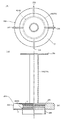
図1は、本発明に係る冷媒容器の第1実施形態を示す部分切欠半縦断面図である。
[First Embodiment]
FIG. 1 is a partially cut-out half vertical sectional view showing a first embodiment of a refrigerant container according to the present invention.
図示実施形態の冷媒容器1は、例えば電気自動車用カーエアコンを構成するヒートポンプシステムに用いられるもので、ステンレスあるいはアルミ合金等の金属製の、下面が開口した天面部付き円筒状のタンク10を有し、このタンク10の下面開口は、同じ金属製の底蓋部材12により気密的に閉塞されている。なお、本実施形態の冷媒容器1は、例えば、図示のように縦置き、つまり、底蓋部材12を下(地)側、タンク10の天面部13を上(天)側にして設置される。
The
底蓋部材12には、いずれも該底蓋部材12を貫通してその上下に開口するように、左端側に気液流入口15、中央に大径の気相用流出口17、右端側に比較的小径の液相用流出口16が並設されている。なお、本実施形態の冷媒容器1では、気液流入口15は凝縮器に接続され、液相用流出口16は膨張弁に接続され、気相用流出口17は圧縮機の吸入側に接続される。
The
気相用流出口17には、タンク10の上部から気相冷媒を当該気相用流出口17に導くための直管(中心線に沿った直線状の管)からなる気相用流出管30が一体的に設けられている。
The gas-
底蓋部材12の上面側中央部分(中央の気相用流出口17と右端側の液相用流出口16を含む部分)には、後述する内蔵ユニット20をスナップフィット式で連結するための環状凹部が形成された短円筒状の内嵌連結部19が突設されている。
An annular for connecting a built-in
また、タンク10内には、内蔵ユニット20が配在されている。この内蔵ユニット20は、例えば合成樹脂製とされ、図2も併せて参照すればよくわかるように、その下部に環状円板状の気液分離促進板22を備える。気液分離促進板22は、気液流入口15からタンク10内に流入した冷媒が衝突して放射状に拡散するとともに、衝突拡散した冷媒がタンク10の内周面と当該気液分離促進板22の外周面との間を通って上側に流動するように、その外径がタンク10の内径より若干小さくされるとともに、その内径が後述するストレーナ40の内径と略等しい環状円板とされ、その下面が前記気液流入口15と対向するように底蓋部材12(における気液流入口15)の上面から所定距離上側に配置されている。
A built-in
また、気液分離促進板22の下面側中央には、前記底蓋部材12に設けられた内嵌連結部19の環状凹部に嵌り込む環状突起が形成された短円筒状の外嵌連結部29が下向きに突設されている。このようにされることにより、底蓋部材12と内蔵ユニット20とをスナップフィット式で連結できるので、組み立てが簡単容易となっている。
In addition, a short cylindrical outer
前記気液分離促進板22の上面側中央には、ストレーナ40が設けられるとともに、その上面側外周の4箇所には等角度間隔(すなわち90°間隔)で補強立板部23が立設されており、該補強立板部23の外周部はタンク10の内周に当接せしめられている。
A
前記ストレーナ40の上側で補強立板部23の内周側には、円筒状ないし平面視C字状に巻かれた乾燥剤M入りバッグ70の略全体が押し込まれて保持される有底円筒状のバッグ保持部24が一体的に設けられている。バッグ保持部24には、肉厚方向に冷媒を通すための複数の長穴26が形成されている。なお、バッグ保持部24内に収容されるバッグ70は、通気性・通水性並びに所要の形状保持性を有するフェルト等の布状体で作製され、その中に粒状の乾燥剤Mが略満杯に充填されており、所定の高さを有している。また、バッグ保持部24の内周側には、前記気相用流出管30が内挿(圧入)される小径短円筒状の中央筒状部27が設けられており、バッグ保持部24内に収容されたバッグ70の内側に、若干の隙間を持って前記気相用流出管30が内挿されている。勿論、中央筒状部27に気相用流出管30を圧入し、その後、バッグ保持部24の内壁に沿うようにバッグ70を挿入しても良い。
On the inner peripheral side of the reinforcing
一方、前記ストレーナ40は、気液分離促進板22上に一体に設けられており、円筒状の網目フィルタ45と、この網目フィルタ45が固着されたケース部42とからなっている。網目フィルタ45は、例えば、金網や合成樹脂製のメッシュ材等から作製される。ケース部42は、上下の環状円板部とそれらの間に位置する補強立板部23の内周端部(4箇所)とで構成されている。すなわち、4本の柱状部(内周端部)の間に側面視矩形の4つの窓が画成され、この各窓部分に網目フィルタ45が張られていることになる。なお、網目フィルタ45は、ケース部42(内蔵ユニット20)の成形時にインサート成形により一体化されても良い。
On the other hand, the
前記底蓋部材12に一体に設けられた気相用流出管30の下端部近く、言い換えれば、網目フィルタ45の内側で液相用流出口16より上側に、オイル戻し孔36が設けられている。このオイル戻し孔36の孔径は例えば1mm前後に設定されている。
An
上記に加え、本実施形態の冷媒容器1は、冷房運転時にはレシーバとして機能させるとともに、暖房運転時にはアキュームレータとして機能させる必要があるため、図示は省略されているが、気相用流出口17(あるいは、それに続く気相冷媒導出流路)を、冷房運転時には閉じ、暖房運転時には開く例えば電磁式の開閉弁が一体的又は別体で設けられる。
In addition to the above, the
このような構成とされた冷媒容器1の冷房運転時と暖房運転時の動作を説明する。
The operation | movement at the time of air_conditionaing | cooling operation and heating operation of the refrigerant |
冷房運転時及び暖房運転時のいずれも、凝縮器から気液流入口15を介してタンク10内に上向きに導入された気液混在状態の冷媒は、気液分離促進板22下面の左端近くに衝突して放射状に拡散され、衝突拡散した冷媒がタンク10の内周面と当該気液分離促進板22の外周面との間の隙間を通って上側に向かって整流化されて、液相冷媒と気相冷媒とが効果的に分離される。この場合、液相冷媒(オイルを含む)はタンク10の下部空間に溜まるとともに、気相冷媒はタンク10の上部空間に上昇する。
In both the cooling operation and the heating operation, the gas-liquid mixed refrigerant introduced upward into the
冷房運転時には、前記開閉弁が閉弁状態(電源OFF)とされ、気相用流出口17が閉じられるので、気相冷媒は圧縮機吸入側には導出されない。
During the cooling operation, the on-off valve is closed (power OFF) and the gas-
また、この冷房運転時には、タンク10の下部空間に溜まった液相冷媒は、タンク10内部と膨張弁側との圧力差により、ストレーナ40(の網目フィルタ45)を通って液相用流出口16から膨張弁に導かれる。
Further, during this cooling operation, the liquid-phase refrigerant accumulated in the lower space of the
したがって、この冷房運転時には、本実施形態の冷媒容器1はレシーバ(レシーバドライヤー)として機能する。
Therefore, during this cooling operation, the
それに対し、暖房運転時には、前記開閉弁が開弁状態(電源ON)とされ、気相用流出口17が開かれるので、気相冷媒は、タンク10の上部空間→気相用流出管30→気相用流出口17を介して圧縮機吸入側に直接吸入されて循環せしめられる。
On the other hand, during the heating operation, the on-off valve is opened (power ON) and the gas-
この暖房運転時には、タンク10の下部空間に溜まった液相冷媒は、圧力差の関係で膨張弁へはほとんど流れない。
During this heating operation, the liquid refrigerant accumulated in the lower space of the
また、液相冷媒とともにタンク10の下部空間に溜まるオイルは、液相冷媒との比重や性状の相違等によりタンク10の底蓋部材12側に移動していき、気相用流出管30を介して圧縮機吸入側に吸入される気相冷媒に吸引されて、ストレーナ40の網目フィルタ45→気液流出管30の下端部付近に設けられたオイル戻し孔36を通って気相冷媒とともに圧縮機吸入側に戻されて循環せしめられる。網目フィルタ45を通る際にはスラッジ等の異物が捕捉され、異物は、循環する冷媒(オイルを含む)から取り除かれる。
Also, the oil accumulated in the lower space of the
したがって、この暖房運転時には、本実施形態の冷媒容器1はアキュームレータとして機能する。
Therefore, during this heating operation, the
上記のように、本実施形態の冷媒容器1は、レシーバ機能とアキュームレータ機能を併せ持ちながら、レシーバとアキュームレータにおけるタンク部分(タンク10)、流入口部分(気液流入口15)、気液分離部分(気液分離促進板22)、及びストレーナ部分(ストレーナ40)を共用化しているので、部品点数の少ない合理的な構造とすることができ、そのため、当該冷媒容器1が採用されたヒートポンプシステムでは、システム全体の占有スペースの縮小化、部品点数の削減等が図られ、コスト低減や小型化等を効果的に図ることができる。
As described above, the
また、当該冷媒容器1に開閉弁を付設して、該開閉弁の開閉(ON−OFF)でシステムの運転状態に応じてレシーバとして機能する状態とアキュームレータとして機能する状態とを切り換えられるようにされているので、例えば外部に開閉弁を設ける場合に比して、システムの配管系等をシンプルなものとすることができる。
Further, an opening / closing valve is attached to the
上記に加え、本実施形態の冷媒容器1では、気液混在状態の冷媒をタンク10の下部に設けられた気液流入口15からタンク10内に上向きに導入して、気液分離促進板22に衝突させて放射状に拡散させ、衝突拡散した冷媒がタンク10の内周面と当該気液分離促進板22の外周面との間の隙間を通って液相冷媒が撹拌されるとともに、気相冷媒が液内で上昇することによっても液相冷媒がさらに撹拌される。このようにタンク10に溜まる液相冷媒を撹拌することにより、液相冷媒が一気に爆発的に沸騰する突沸現象及びそれに伴う衝撃音の発生を抑えることが可能となる。
In addition to the above, in the
[第2実施形態]
図3は、本発明に係る冷媒容器の第2実施形態を示す部分切欠半縦断面図である。
[Second Embodiment]
FIG. 3 is a partially cut-out half longitudinal sectional view showing a second embodiment of the refrigerant container according to the present invention.
図示実施形態の冷媒容器2が、前述した第1実施形態の冷媒容器1と相違するのは、内蔵ユニット20におけるバッグ保持部の構造と、底蓋部材12と内蔵ユニット20との連結構造部分であり、他の部分は基本的には同じであるので、以下においては相違点のみを説明する。
The
本実施形態の冷媒容器2では、底蓋部材12の上面側中央部分には、内蔵ユニット20Aをねじ込み式で連結するための雄ねじ部19Aが設けられる一方、内蔵ユニット20A側には、前記雄ねじ部19Aに螺合する雌ねじ部29Aが設けられている。このようなねじ込み式でも、組み立てが簡単容易となる。
In the
また、本実施形態では、図3に加えて図4を参照すればよくわかるように、内蔵ユニット20Aにおけるストレーナ40の上側で補強立板部23Aの内周側に、前記気相用流出管30が内挿される小径の長円筒部27Aを持つボビン状のバッグ保持部24Aが設けられている。このボビン状のバッグ保持部24Aは、その長円筒部27Aに乾燥剤M入りバッグ70を巻き付けてその外周に結束バンド28を巻き回して固定保持するようになっている。この場合、保持されているバッグ70は円筒形ないし平面視C字状となっており、バッグ70の上端及び下端は、バッグ保持部24Aの上下一対のフランジ部25a、26bに若干押し付けられている。
In the present embodiment, as can be understood by referring to FIG. 4 in addition to FIG. 3, the gas-
他の構成は、基本的には上記第1実施形態と略同じであり、上記第1実施形態と略同様な作用効果が得られることは詳述するまでも無い。 Other configurations are basically the same as those of the first embodiment, and it is needless to mention that substantially the same functions and effects as those of the first embodiment can be obtained.
なお、上述の実施形態においては、気相用流出口17を開閉弁で開閉するようにされているが、それに加えて、液相用流出口16を開閉するための開閉弁を設けて、該開閉弁を気相冷媒側とは逆理で開閉するようにしてもよく、さらに、気相用と液相用の開閉弁を纏めて四方弁としてもよい。
In the above-described embodiment, the gas-
また、当該冷媒容器1に上記開閉弁や四方弁を必ずしも設ける必要はなく、それらを外部流路、例えば液相用流出口と膨張弁とを結ぶ流路や気相用流出口と圧縮機吸入側とを結ぶ流路に介装するようにしてもよい。
In addition, it is not always necessary to provide the on-off valve and the four-way valve in the
1 冷媒容器(第1実施形態)
2 冷媒容器(第2実施形態)
10 タンク
12 底蓋部材
13 タンクの天面部
15 気液流入口
16 液相用流出口
17 気相用流出口
20 内蔵ユニット
22 気液分離促進板
23 補強立板部
24 バッグ保持部
30 気相用流出管
36 オイル戻し孔
40 ストレーナ
45 網目フィルタ
70 バッグ
M 乾燥剤
1 Refrigerant container (first embodiment)
2 Refrigerant container (second embodiment)
DESCRIPTION OF
Claims (7)
前記気液流入口は、前記気液流入口から導入される気液混在状態の冷媒によって、前記タンクの底部付近に溜まった液相冷媒が撹拌される位置に設けられており、
前記タンク内に、前記気液流入口から流入する冷媒が衝突するように前記タンクの内径より小径の気液分離促進板が配在されるとともに、前記気相用流出口に、前記タンクの上部から気相冷媒を該気相用流出口に導く気相用流出管が設けられ、該気相用流出管の下端部にストレーナが設けられ、前記気液分離促進板と前記ストレーナとが一体に設けられていることを特徴とする冷媒容器。 It has a tank that can temporarily store the refrigerant, and a gas-liquid inlet, a liquid-phase outlet, and a gas-phase outlet are provided in the lower part of the tank, and are introduced from the gas-liquid inlet. A receiver function for separating the separated refrigerant into a liquid-phase refrigerant and a gas-phase refrigerant, and leading only the separated liquid-phase refrigerant to the expansion valve side via the liquid-phase outlet, and the separated gas-phase refrigerant Combined with the accumulator function that leads the refrigerant to the compressor suction side through the gas-phase outlet with the oil contained in the liquid-phase refrigerant,
The gas-liquid inlet is provided at a position where the liquid-phase refrigerant accumulated near the bottom of the tank is stirred by the gas-liquid mixed refrigerant introduced from the gas-liquid inlet ,
A gas-liquid separation promoting plate having a diameter smaller than the inner diameter of the tank is disposed in the tank so that the refrigerant flowing from the gas-liquid inlet collides with the tank, and the upper part of the tank is disposed at the gas-phase outlet. A gas-phase outflow pipe for introducing the gas-phase refrigerant from the gas-phase outlet to the gas-phase outlet, a strainer is provided at the lower end of the gas-phase outflow pipe, and the gas-liquid separation promoting plate and the strainer are integrated with each other. refrigerant container shall be the being provided.
Priority Applications (6)
| Application Number | Priority Date | Filing Date | Title |
|---|---|---|---|
| JP2016252843A JP6587602B2 (en) | 2016-12-27 | 2016-12-27 | Refrigerant container |
| EP17885677.9A EP3495754A4 (en) | 2016-12-27 | 2017-10-17 | Refrigerant container |
| US16/314,183 US10821811B2 (en) | 2016-12-27 | 2017-10-17 | Refrigerant container |
| PCT/JP2017/037449 WO2018123216A1 (en) | 2016-12-27 | 2017-10-17 | Refrigerant container |
| KR1020187025747A KR102330879B1 (en) | 2016-12-27 | 2017-10-17 | refrigerant container |
| CN201780024040.1A CN109073298B (en) | 2016-12-27 | 2017-10-17 | Refrigerant container |
Applications Claiming Priority (1)
| Application Number | Priority Date | Filing Date | Title |
|---|---|---|---|
| JP2016252843A JP6587602B2 (en) | 2016-12-27 | 2016-12-27 | Refrigerant container |
Publications (3)
| Publication Number | Publication Date |
|---|---|
| JP2018105554A JP2018105554A (en) | 2018-07-05 |
| JP2018105554A5 JP2018105554A5 (en) | 2018-09-06 |
| JP6587602B2 true JP6587602B2 (en) | 2019-10-09 |
Family
ID=62710918
Family Applications (1)
| Application Number | Title | Priority Date | Filing Date |
|---|---|---|---|
| JP2016252843A Active JP6587602B2 (en) | 2016-12-27 | 2016-12-27 | Refrigerant container |
Country Status (6)
| Country | Link |
|---|---|
| US (1) | US10821811B2 (en) |
| EP (1) | EP3495754A4 (en) |
| JP (1) | JP6587602B2 (en) |
| KR (1) | KR102330879B1 (en) |
| CN (1) | CN109073298B (en) |
| WO (1) | WO2018123216A1 (en) |
Families Citing this family (2)
| Publication number | Priority date | Publication date | Assignee | Title |
|---|---|---|---|---|
| EP3936793A4 (en) * | 2019-03-05 | 2022-11-16 | Fujikoki Corporation | Refrigerant container |
| CN114370726A (en) * | 2022-01-21 | 2022-04-19 | 天津双昊车用空调有限公司 | Gas-liquid separator with liquid accumulator function |
Family Cites Families (31)
| Publication number | Priority date | Publication date | Assignee | Title |
|---|---|---|---|---|
| JPS572371U (en) * | 1980-06-06 | 1982-01-07 | ||
| US4458505A (en) * | 1983-03-25 | 1984-07-10 | Parker-Hannifin Corporation | Suction line accumulator |
| JPH02169970A (en) * | 1988-12-22 | 1990-06-29 | Nippondenso Co Ltd | Liquid reservoir |
| JPH0461262A (en) | 1990-06-28 | 1992-02-27 | Ibiden Co Ltd | Electronic component mounting board |
| JPH0731093Y2 (en) * | 1990-09-27 | 1995-07-19 | 新明和工業株式会社 | Refrigeration equipment |
| JPH07146035A (en) * | 1993-11-19 | 1995-06-06 | Mitsubishi Electric Corp | Oil separator |
| JP3510673B2 (en) * | 1994-06-15 | 2004-03-29 | 三洋電機株式会社 | accumulator |
| JPH0968371A (en) * | 1995-08-31 | 1997-03-11 | Nippon Soken Inc | Gas/liquid separator |
| JP3339332B2 (en) * | 1996-11-06 | 2002-10-28 | 三菱電機株式会社 | Accumulator, refrigeration cycle device |
| JPH10170107A (en) * | 1996-12-10 | 1998-06-26 | Mitsubishi Heavy Ind Ltd | Reversible direction receiver |
| KR20030062872A (en) * | 2002-01-21 | 2003-07-28 | 엘지전자 주식회사 | Accumulator/receiver assembly for air conditioner |
| JP4091416B2 (en) | 2002-12-27 | 2008-05-28 | 昭和電工株式会社 | Receiver tank for refrigeration cycle, heat exchanger with receiver tank, and condensing device for refrigeration cycle |
| JP4776438B2 (en) * | 2006-05-26 | 2011-09-21 | サンデン株式会社 | Refrigeration cycle |
| KR20080010182A (en) * | 2006-07-26 | 2008-01-30 | 현대자동차주식회사 | Receiver drier |
| JP2008075894A (en) * | 2006-09-19 | 2008-04-03 | Daikin Ind Ltd | Gas-liquid separator |
| JP2007085730A (en) * | 2006-12-18 | 2007-04-05 | Mitsubishi Electric Corp | Air conditioner and method of operating air conditioner |
| JP2008196721A (en) * | 2007-02-08 | 2008-08-28 | Mitsubishi Heavy Ind Ltd | Gas-liquid separator |
| JP2012093051A (en) * | 2010-10-28 | 2012-05-17 | Fuji Koki Corp | Gas-liquid separator for heat pump and injection type heat pump system |
| JP2012136147A (en) | 2010-12-27 | 2012-07-19 | Tgk Co Ltd | Vehicle air conditioner |
| WO2012108149A1 (en) * | 2011-02-08 | 2012-08-16 | パナソニック株式会社 | Gas liquid separator and freeze cycle device |
| JP2015034637A (en) * | 2011-11-22 | 2015-02-19 | パナソニック株式会社 | Gas-liquid separator and refrigeration cycle device |
| JP5982114B2 (en) * | 2011-11-24 | 2016-08-31 | 株式会社不二工機 | Gas-liquid separator |
| JP2013184596A (en) | 2012-03-08 | 2013-09-19 | Denso Corp | Refrigerating cycle device for air-conditioning vehicle and for temperature-conditioning parts constituting vehicle |
| JP2013245917A (en) * | 2012-05-29 | 2013-12-09 | Panasonic Corp | Gas-liquid separator and refrigerating cycle device |
| JP5861574B2 (en) * | 2012-06-22 | 2016-02-16 | 株式会社デンソー | Pressure reducing device and refrigeration cycle device |
| CN103575001B (en) * | 2012-07-25 | 2016-03-02 | 珠海格力电器股份有限公司 | Flash vessel and comprise the air-conditioner of this flash vessel |
| JP6068938B2 (en) * | 2012-11-08 | 2017-01-25 | 株式会社不二工機 | accumulator |
| JP6055291B2 (en) * | 2012-11-27 | 2016-12-27 | 株式会社不二工機 | accumulator |
| DE102013206357A1 (en) * | 2013-04-11 | 2014-10-16 | Behr Gmbh & Co. Kg | collector |
| JP2016114308A (en) * | 2014-12-16 | 2016-06-23 | 東芝キヤリア株式会社 | Intermediate pressure receiver and refrigeration cycle device |
| JP6600654B2 (en) * | 2016-10-25 | 2019-10-30 | 株式会社不二工機 | accumulator |
-
2016
- 2016-12-27 JP JP2016252843A patent/JP6587602B2/en active Active
-
2017
- 2017-10-17 US US16/314,183 patent/US10821811B2/en active Active
- 2017-10-17 EP EP17885677.9A patent/EP3495754A4/en active Pending
- 2017-10-17 CN CN201780024040.1A patent/CN109073298B/en active Active
- 2017-10-17 WO PCT/JP2017/037449 patent/WO2018123216A1/en unknown
- 2017-10-17 KR KR1020187025747A patent/KR102330879B1/en active IP Right Grant
Also Published As
| Publication number | Publication date |
|---|---|
| CN109073298B (en) | 2021-06-22 |
| JP2018105554A (en) | 2018-07-05 |
| KR102330879B1 (en) | 2021-11-24 |
| US10821811B2 (en) | 2020-11-03 |
| EP3495754A1 (en) | 2019-06-12 |
| WO2018123216A1 (en) | 2018-07-05 |
| US20190160918A1 (en) | 2019-05-30 |
| KR20190102137A (en) | 2019-09-03 |
| CN109073298A (en) | 2018-12-21 |
| EP3495754A4 (en) | 2020-04-08 |
Similar Documents
| Publication | Publication Date | Title |
|---|---|---|
| US10926608B2 (en) | Refrigerant container | |
| CN106352618B (en) | Storage device | |
| JP6587602B2 (en) | Refrigerant container | |
| JP6155005B2 (en) | accumulator | |
| CN113439189B (en) | Liquid storage device | |
| CN109964090B (en) | Liquid storage device | |
| CN106352620B (en) | Liquid storage device | |
| EP3671074B1 (en) | Accumulator | |
| WO2019107011A1 (en) | Accumulator | |
| JP5982114B2 (en) | Gas-liquid separator | |
| WO2018079182A1 (en) | Accumulator | |
| JP6055278B2 (en) | accumulator | |
| KR20100085258A (en) | Accumulator for refrigerator | |
| JP2019086211A (en) | Liquid reservoir |
Legal Events
| Date | Code | Title | Description |
|---|---|---|---|
| A521 | Request for written amendment filed |
Free format text: JAPANESE INTERMEDIATE CODE: A523 Effective date: 20180723 |
|
| A621 | Written request for application examination |
Free format text: JAPANESE INTERMEDIATE CODE: A621 Effective date: 20180723 |
|
| A131 | Notification of reasons for refusal |
Free format text: JAPANESE INTERMEDIATE CODE: A131 Effective date: 20190514 |
|
| A521 | Request for written amendment filed |
Free format text: JAPANESE INTERMEDIATE CODE: A523 Effective date: 20190606 |
|
| TRDD | Decision of grant or rejection written | ||
| A01 | Written decision to grant a patent or to grant a registration (utility model) |
Free format text: JAPANESE INTERMEDIATE CODE: A01 Effective date: 20190813 |
|
| A61 | First payment of annual fees (during grant procedure) |
Free format text: JAPANESE INTERMEDIATE CODE: A61 Effective date: 20190910 |
|
| R150 | Certificate of patent or registration of utility model |
Ref document number: 6587602 Country of ref document: JP Free format text: JAPANESE INTERMEDIATE CODE: R150 |
|
| R250 | Receipt of annual fees |
Free format text: JAPANESE INTERMEDIATE CODE: R250 |
|
| R250 | Receipt of annual fees |
Free format text: JAPANESE INTERMEDIATE CODE: R250 |