EP3118492A1 - Structure for securing diaphragm, diaphragm pump and valve device provided with said structure, and method for securing diaphragm - Google Patents
Structure for securing diaphragm, diaphragm pump and valve device provided with said structure, and method for securing diaphragm Download PDFInfo
- Publication number
- EP3118492A1 EP3118492A1 EP15764809.8A EP15764809A EP3118492A1 EP 3118492 A1 EP3118492 A1 EP 3118492A1 EP 15764809 A EP15764809 A EP 15764809A EP 3118492 A1 EP3118492 A1 EP 3118492A1
- Authority
- EP
- European Patent Office
- Prior art keywords
- frame
- diaphragm
- arm portions
- chest
- securing
- Prior art date
- Legal status (The legal status is an assumption and is not a legal conclusion. Google has not performed a legal analysis and makes no representation as to the accuracy of the status listed.)
- Granted
Links
- 238000000034 method Methods 0.000 title claims description 11
- 239000012530 fluid Substances 0.000 claims description 49
- 238000006073 displacement reaction Methods 0.000 claims description 24
- 210000000038 chest Anatomy 0.000 description 56
- 210000002445 nipple Anatomy 0.000 description 10
- 230000000717 retained effect Effects 0.000 description 9
- 239000012528 membrane Substances 0.000 description 8
- 239000000463 material Substances 0.000 description 6
- -1 polypropylene Polymers 0.000 description 6
- 238000005520 cutting process Methods 0.000 description 5
- 238000010586 diagram Methods 0.000 description 5
- 230000000295 complement effect Effects 0.000 description 4
- 229920001971 elastomer Polymers 0.000 description 4
- 238000004519 manufacturing process Methods 0.000 description 3
- 238000003825 pressing Methods 0.000 description 3
- 239000000126 substance Substances 0.000 description 3
- 229920002943 EPDM rubber Polymers 0.000 description 2
- 239000004696 Poly ether ether ketone Substances 0.000 description 2
- 239000004734 Polyphenylene sulfide Substances 0.000 description 2
- 239000004743 Polypropylene Substances 0.000 description 2
- 238000004458 analytical method Methods 0.000 description 2
- 230000005489 elastic deformation Effects 0.000 description 2
- 230000002093 peripheral effect Effects 0.000 description 2
- 229920002530 polyetherether ketone Polymers 0.000 description 2
- 229920000642 polymer Polymers 0.000 description 2
- 229920006324 polyoxymethylene Polymers 0.000 description 2
- 229920000069 polyphenylene sulfide Polymers 0.000 description 2
- 229920001343 polytetrafluoroethylene Polymers 0.000 description 2
- 239000004810 polytetrafluoroethylene Substances 0.000 description 2
- XEEYBQQBJWHFJM-UHFFFAOYSA-N Iron Chemical group [Fe] XEEYBQQBJWHFJM-UHFFFAOYSA-N 0.000 description 1
- 229920000459 Nitrile rubber Polymers 0.000 description 1
- 229920006169 Perfluoroelastomer Polymers 0.000 description 1
- 229930182556 Polyacetal Natural products 0.000 description 1
- 239000000853 adhesive Substances 0.000 description 1
- 230000001070 adhesive effect Effects 0.000 description 1
- 230000004888 barrier function Effects 0.000 description 1
- JUPQTSLXMOCDHR-UHFFFAOYSA-N benzene-1,4-diol;bis(4-fluorophenyl)methanone Chemical compound OC1=CC=C(O)C=C1.C1=CC(F)=CC=C1C(=O)C1=CC=C(F)C=C1 JUPQTSLXMOCDHR-UHFFFAOYSA-N 0.000 description 1
- 230000003247 decreasing effect Effects 0.000 description 1
- 238000007599 discharging Methods 0.000 description 1
- 229910052571 earthenware Inorganic materials 0.000 description 1
- 230000000694 effects Effects 0.000 description 1
- 239000013013 elastic material Substances 0.000 description 1
- 230000007613 environmental effect Effects 0.000 description 1
- 229920001973 fluoroelastomer Polymers 0.000 description 1
- 239000004570 mortar (masonry) Substances 0.000 description 1
- 229920001155 polypropylene Polymers 0.000 description 1
- 229920002379 silicone rubber Polymers 0.000 description 1
- 239000004945 silicone rubber Substances 0.000 description 1
- 238000009751 slip forming Methods 0.000 description 1
- 125000000383 tetramethylene group Chemical group [H]C([H])([*:1])C([H])([H])C([H])([H])C([H])([H])[*:2] 0.000 description 1
Images




Classifications
-
- F—MECHANICAL ENGINEERING; LIGHTING; HEATING; WEAPONS; BLASTING
- F04—POSITIVE - DISPLACEMENT MACHINES FOR LIQUIDS; PUMPS FOR LIQUIDS OR ELASTIC FLUIDS
- F04B—POSITIVE-DISPLACEMENT MACHINES FOR LIQUIDS; PUMPS
- F04B45/00—Pumps or pumping installations having flexible working members and specially adapted for elastic fluids
- F04B45/04—Pumps or pumping installations having flexible working members and specially adapted for elastic fluids having plate-like flexible members, e.g. diaphragms
-
- F—MECHANICAL ENGINEERING; LIGHTING; HEATING; WEAPONS; BLASTING
- F04—POSITIVE - DISPLACEMENT MACHINES FOR LIQUIDS; PUMPS FOR LIQUIDS OR ELASTIC FLUIDS
- F04B—POSITIVE-DISPLACEMENT MACHINES FOR LIQUIDS; PUMPS
- F04B43/00—Machines, pumps, or pumping installations having flexible working members
- F04B43/0009—Special features
- F04B43/0054—Special features particularities of the flexible members
-
- F—MECHANICAL ENGINEERING; LIGHTING; HEATING; WEAPONS; BLASTING
- F04—POSITIVE - DISPLACEMENT MACHINES FOR LIQUIDS; PUMPS FOR LIQUIDS OR ELASTIC FLUIDS
- F04B—POSITIVE-DISPLACEMENT MACHINES FOR LIQUIDS; PUMPS
- F04B43/00—Machines, pumps, or pumping installations having flexible working members
- F04B43/02—Machines, pumps, or pumping installations having flexible working members having plate-like flexible members, e.g. diaphragms
- F04B43/06—Pumps having fluid drive
-
- F—MECHANICAL ENGINEERING; LIGHTING; HEATING; WEAPONS; BLASTING
- F04—POSITIVE - DISPLACEMENT MACHINES FOR LIQUIDS; PUMPS FOR LIQUIDS OR ELASTIC FLUIDS
- F04B—POSITIVE-DISPLACEMENT MACHINES FOR LIQUIDS; PUMPS
- F04B43/00—Machines, pumps, or pumping installations having flexible working members
- F04B43/12—Machines, pumps, or pumping installations having flexible working members having peristaltic action
- F04B43/14—Machines, pumps, or pumping installations having flexible working members having peristaltic action having plate-like flexible members
-
- F—MECHANICAL ENGINEERING; LIGHTING; HEATING; WEAPONS; BLASTING
- F04—POSITIVE - DISPLACEMENT MACHINES FOR LIQUIDS; PUMPS FOR LIQUIDS OR ELASTIC FLUIDS
- F04B—POSITIVE-DISPLACEMENT MACHINES FOR LIQUIDS; PUMPS
- F04B53/00—Component parts, details or accessories not provided for in, or of interest apart from, groups F04B1/00 - F04B23/00 or F04B39/00 - F04B47/00
- F04B53/10—Valves; Arrangement of valves
- F04B53/1087—Valve seats
-
- F—MECHANICAL ENGINEERING; LIGHTING; HEATING; WEAPONS; BLASTING
- F04—POSITIVE - DISPLACEMENT MACHINES FOR LIQUIDS; PUMPS FOR LIQUIDS OR ELASTIC FLUIDS
- F04B—POSITIVE-DISPLACEMENT MACHINES FOR LIQUIDS; PUMPS
- F04B53/00—Component parts, details or accessories not provided for in, or of interest apart from, groups F04B1/00 - F04B23/00 or F04B39/00 - F04B47/00
- F04B53/16—Casings; Cylinders; Cylinder liners or heads; Fluid connections
-
- F—MECHANICAL ENGINEERING; LIGHTING; HEATING; WEAPONS; BLASTING
- F15—FLUID-PRESSURE ACTUATORS; HYDRAULICS OR PNEUMATICS IN GENERAL
- F15B—SYSTEMS ACTING BY MEANS OF FLUIDS IN GENERAL; FLUID-PRESSURE ACTUATORS, e.g. SERVOMOTORS; DETAILS OF FLUID-PRESSURE SYSTEMS, NOT OTHERWISE PROVIDED FOR
- F15B15/00—Fluid-actuated devices for displacing a member from one position to another; Gearing associated therewith
- F15B15/08—Characterised by the construction of the motor unit
- F15B15/10—Characterised by the construction of the motor unit the motor being of diaphragm type
-
- F—MECHANICAL ENGINEERING; LIGHTING; HEATING; WEAPONS; BLASTING
- F16—ENGINEERING ELEMENTS AND UNITS; GENERAL MEASURES FOR PRODUCING AND MAINTAINING EFFECTIVE FUNCTIONING OF MACHINES OR INSTALLATIONS; THERMAL INSULATION IN GENERAL
- F16J—PISTONS; CYLINDERS; SEALINGS
- F16J15/00—Sealings
- F16J15/50—Sealings between relatively-movable members, by means of a sealing without relatively-moving surfaces, e.g. fluid-tight sealings for transmitting motion through a wall
- F16J15/52—Sealings between relatively-movable members, by means of a sealing without relatively-moving surfaces, e.g. fluid-tight sealings for transmitting motion through a wall by means of sealing bellows or diaphragms
-
- F—MECHANICAL ENGINEERING; LIGHTING; HEATING; WEAPONS; BLASTING
- F16—ENGINEERING ELEMENTS AND UNITS; GENERAL MEASURES FOR PRODUCING AND MAINTAINING EFFECTIVE FUNCTIONING OF MACHINES OR INSTALLATIONS; THERMAL INSULATION IN GENERAL
- F16J—PISTONS; CYLINDERS; SEALINGS
- F16J3/00—Diaphragms; Bellows; Bellows pistons
- F16J3/02—Diaphragms
-
- F—MECHANICAL ENGINEERING; LIGHTING; HEATING; WEAPONS; BLASTING
- F16—ENGINEERING ELEMENTS AND UNITS; GENERAL MEASURES FOR PRODUCING AND MAINTAINING EFFECTIVE FUNCTIONING OF MACHINES OR INSTALLATIONS; THERMAL INSULATION IN GENERAL
- F16K—VALVES; TAPS; COCKS; ACTUATING-FLOATS; DEVICES FOR VENTING OR AERATING
- F16K11/00—Multiple-way valves, e.g. mixing valves; Pipe fittings incorporating such valves
- F16K11/02—Multiple-way valves, e.g. mixing valves; Pipe fittings incorporating such valves with all movable sealing faces moving as one unit
- F16K11/022—Multiple-way valves, e.g. mixing valves; Pipe fittings incorporating such valves with all movable sealing faces moving as one unit comprising a deformable member
-
- F—MECHANICAL ENGINEERING; LIGHTING; HEATING; WEAPONS; BLASTING
- F16—ENGINEERING ELEMENTS AND UNITS; GENERAL MEASURES FOR PRODUCING AND MAINTAINING EFFECTIVE FUNCTIONING OF MACHINES OR INSTALLATIONS; THERMAL INSULATION IN GENERAL
- F16K—VALVES; TAPS; COCKS; ACTUATING-FLOATS; DEVICES FOR VENTING OR AERATING
- F16K11/00—Multiple-way valves, e.g. mixing valves; Pipe fittings incorporating such valves
- F16K11/02—Multiple-way valves, e.g. mixing valves; Pipe fittings incorporating such valves with all movable sealing faces moving as one unit
- F16K11/04—Multiple-way valves, e.g. mixing valves; Pipe fittings incorporating such valves with all movable sealing faces moving as one unit comprising only lift valves
-
- F—MECHANICAL ENGINEERING; LIGHTING; HEATING; WEAPONS; BLASTING
- F16—ENGINEERING ELEMENTS AND UNITS; GENERAL MEASURES FOR PRODUCING AND MAINTAINING EFFECTIVE FUNCTIONING OF MACHINES OR INSTALLATIONS; THERMAL INSULATION IN GENERAL
- F16K—VALVES; TAPS; COCKS; ACTUATING-FLOATS; DEVICES FOR VENTING OR AERATING
- F16K11/00—Multiple-way valves, e.g. mixing valves; Pipe fittings incorporating such valves
- F16K11/02—Multiple-way valves, e.g. mixing valves; Pipe fittings incorporating such valves with all movable sealing faces moving as one unit
- F16K11/04—Multiple-way valves, e.g. mixing valves; Pipe fittings incorporating such valves with all movable sealing faces moving as one unit comprising only lift valves
- F16K11/052—Multiple-way valves, e.g. mixing valves; Pipe fittings incorporating such valves with all movable sealing faces moving as one unit comprising only lift valves with pivoted closure members, e.g. butterfly valves
- F16K11/0525—Multiple-way valves, e.g. mixing valves; Pipe fittings incorporating such valves with all movable sealing faces moving as one unit comprising only lift valves with pivoted closure members, e.g. butterfly valves the closure members being pivoted around an essentially central axis
-
- F—MECHANICAL ENGINEERING; LIGHTING; HEATING; WEAPONS; BLASTING
- F16—ENGINEERING ELEMENTS AND UNITS; GENERAL MEASURES FOR PRODUCING AND MAINTAINING EFFECTIVE FUNCTIONING OF MACHINES OR INSTALLATIONS; THERMAL INSULATION IN GENERAL
- F16K—VALVES; TAPS; COCKS; ACTUATING-FLOATS; DEVICES FOR VENTING OR AERATING
- F16K31/00—Actuating devices; Operating means; Releasing devices
- F16K31/02—Actuating devices; Operating means; Releasing devices electric; magnetic
- F16K31/06—Actuating devices; Operating means; Releasing devices electric; magnetic using a magnet, e.g. diaphragm valves, cutting off by means of a liquid
- F16K31/0603—Multiple-way valves
- F16K31/0641—Multiple-way valves the valve member being a diaphragm
-
- F—MECHANICAL ENGINEERING; LIGHTING; HEATING; WEAPONS; BLASTING
- F16—ENGINEERING ELEMENTS AND UNITS; GENERAL MEASURES FOR PRODUCING AND MAINTAINING EFFECTIVE FUNCTIONING OF MACHINES OR INSTALLATIONS; THERMAL INSULATION IN GENERAL
- F16K—VALVES; TAPS; COCKS; ACTUATING-FLOATS; DEVICES FOR VENTING OR AERATING
- F16K31/00—Actuating devices; Operating means; Releasing devices
- F16K31/02—Actuating devices; Operating means; Releasing devices electric; magnetic
- F16K31/06—Actuating devices; Operating means; Releasing devices electric; magnetic using a magnet, e.g. diaphragm valves, cutting off by means of a liquid
- F16K31/10—Actuating devices; Operating means; Releasing devices electric; magnetic using a magnet, e.g. diaphragm valves, cutting off by means of a liquid with additional mechanism between armature and closure member
- F16K31/105—Actuating devices; Operating means; Releasing devices electric; magnetic using a magnet, e.g. diaphragm valves, cutting off by means of a liquid with additional mechanism between armature and closure member for rotating valves
Definitions
- the present invention relates to a structure for securing a diaphragm which divides a space into a first chest and a second chest, to a case which forms the space therein, a diaphragm pump and a valve device which are equipped with the same, and a method of securing a diaphragm.
- Patent document 1 discloses a diaphragm pump having a structure such that a diaphragm is secured between a pair of frames, wherein the frames are mutually-coupled by the use of pairs of screws and screw nuts in order to suppress a leakage of the fluid from an edge portion of the diaphragm.
- Patent document 1 Japanese Patent Application Publication No. H11-183359
- the leakage of the fluid is caused when the force of the paired frames pressing the diaphragm becomes insufficient locally or overall. Therefore, in the structure for securing the diaphragm, a large number of screws and nuts are used in order to press the diaphragm evenly by a sufficient force.
- a primary object is to provide a structure for securing a diaphragm and others capable of achieving a cost-cutting by reducing the number of parts and making the assembling easy.
- the present invention is a structure for securing a diaphragm which divides a space into a first chest and a second chest, to a case which forms the space therein, characterized in that the case has a first frame having a first concave portion defining the first chest, and a second frame having a second concave portion defining the second chest, the first frame has a first frame main body opposed to the second frame, and first arm portions disposed intermittently along an outer edge of the first frame main body and extending toward the second frame, the second frame has a second frame main body opposed to the first frame, and second arm portions disposed intermittently along an outer edge of the second frame main body and extending toward the first frame, and an edge portion of the diaphragm is compressed and secured between the first frame and the second frame which are fitted with each other, and characterized by further comprising a fastener for constricting the first arm portions and the second arm portions from the outer side of the case.
- the first arm portions and the second arm portions are provided with a positional displacement preventing means to maintain the position of the fastener.
- the positional displacement preventing means comprises a first retaining projection disposed on each of the first arm portions and jutting out outwardly of the case on the second frame main body side of the fastener, and a second retaining projection disposed on each of the second arm portions and jutting out outwardly of the case on the first frame main body side of the fastener.
- the positional displacement preventing means is an annular groove extending along an outer edge of the case in the outer circumference surfaces of the first arm portions and the second arm portions.
- first arm portions and the second arm portions are alternately dispersed along the outer edge of the case.
- first arm portions and the second arm portions are continuously provided along the outer circumference of the case.
- the edge portion of the diaphragm is provided with a thick part having a larger thickness.
- the first frame and/or the second frame are provided with a positioning groove at which the thick part is disposed.
- the present invention is a diaphragm pump equipped with the structure for securing a diaphragm as set forth in any one of claims 1-8 and characterized in that the first frame is provided with a first port communicating with the first chest, the second frame is provided with a second port communicating with the second chest, a fluid for driving the diaphragm is fed to the first chest via the first port, and a fluid being treated flows in and flows out of the second chest via the second port.
- the present invention is a valve device equipped with the structure for securing a diaphragm as set forth in claims 1-8, and characterized in that the first chest of the first frame is provided with a driving means for driving the diaphragm, the second frame has an inflow port for allowing the fluid to flow into the second chest, and an outflow port for allowing the fluid to flow out of the second chest, the outflow port has an opening around which a valve seat is formed, and the diaphragm sits on and leaves the valve seat to close and open the outflow port.
- the present invention is a method for securing a diaphragm which divides a space into a first chest and a second chest, to a case which forms the space therein, characterized in that the case has a first frame having a first concave portion defining the first chest, and a second frame having a second concave portion defining the second chest, the first frame has a first frame main body opposed to the second frame, and first arm portions disposed intermittently along an outer edge of the first frame main body and extending toward the second frame, and the second frame has a second frame main body opposed to the first frame, and second arm portions disposed intermittently along an outer edge of the second frame main body and extending toward the first frame, and characterized by comprising a fitting step of fitting the first frame with the second frame, a diaphragm holding step of compressing and folding an edge portion of the diaphragm between the first frame and the second frame, and a fastener attaching step of constricting the first frame and the second frame by attaching a fast
- the present invention is the diaphragm securing structure for securing the diaphragm which divides the space into the first chest and the second chest, to the case which forms the space therein, wherein the case has the first frame having the first concave portion defining the first chest, and the second frame having the second concave portion defining the second chest, and the edge portion of the diaphragm is compressed and held between the first frame and the second frame which are fitted with each other, whereby the fluid being treated is suppressed from leaking from the edge portion of the diaphragm.
- the first frame has the first frame main body opposed to the second frame, and the first arm portions disposed intermittently along the outer edge of the first frame main body and extending toward the second frame
- the second frame has the second frame main body opposed to the first frame, and the second arm portions disposed intermittently along the outer edge of the second frame main body and extending toward the first frame.
- the structure for securing a diaphragm comprises the fastener for constricting the first arm portions and the second arm portions from the outside of the case, therefore, it is possible to achieve a state in which the first frame and the second frame are firmly fitted with each other.
- the diaphragm pump according to the present invention has the structure for securing a diaphragm, wherein the fluid for driving the diaphragm is fed to the first chest of the first frame via the first port, and the fluid being treated flows in and flows out of the second chest via the second port.
- the diaphragm pump has the simple and inexpensive structure, it is possible to feed an accurate quantity of the fluid being treated.
- the valve device has the structure for securing a diaphragm, wherein the first chest of the first frame is provided with the driving means for driving the diaphragm, the second frame has the inflow port for allowing the fluid to flow into the second chest, and the outflow port for allowing the fluid to flow out of the second chest, the outflow port has the opening around which the valve seat is formed, and the diaphragm sits on and leaves the valve seat to close and open the outflow port.
- the method of securing a diaphragm according to the present invention comprises the frame fitting step of fitting the first frame and the second frame with each other. Thereby, the first frame and the second frame are firmly fitted with each other with sufficient strength.
- the securing method further comprises the diaphragm holding step of compressing and folding the edge portion of the diaphragm between the first frame and the second frame, therefore, the fluid being treated can be suppressed from leaking from the edge portion of the diaphragm.
- the securing method further comprises the fastener attaching step of constricting the first frame and the second frame by attaching the fastener from the outside of the case to achieve a strong fitting state, therefore, the first frame and the second frame are firmly united and the leakage of the fluid being treated from the edge portion of the diaphragm can be further suppressed.
- Figure 1 shows a general structure of a diaphragm pump 1 as a first embodiment of the present invention.
- the diaphragm pump 1 is to feed a fluid being treated such as test sample at a constant quantity.
- the diaphragm pump 1 has a case 2 forming a space 20 therein, and a diaphragm 3 dividing the space 20 into a first chest 21 and a second chest 22.
- a fluid such as gas and discharging the fluid
- the diaphragm 3 is driven and transformed, and the fluid is fed from the second chest 22 at a constant quantity.
- the volume of the discharged fluid is determined by the volume of the space 20, the volume of the diaphragm 3 occupying the space 20 and the like.
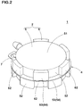
- FIGs 2 and 3 the external appearance of the diaphragm pump 1 is shown.
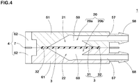
- Figure 4 and Figure 5 there are shown the A-A line section and B-B line section of the diaphragm pump 1 shown in Figure 3 .
- Figure 6 there is shown an assembly perspective diagram of the diaphragm pump 1.
- the diaphragm 3 is secured to the case 2 by a securing structure 4.
- the case 2 of the diaphragm pump 1 has a first frame 5 having a first concave portion 50 and a second frame 6 having a second concave portion 60.
- the first frame 5 and the second frame 6 fitted with each other achieve a stiff fitted state by a fastener 7.
- the first concave portion 50 forms a space 20a on the first chest 21 side.
- the second concave portion 60 forms a space 20b on the second chest 22 side.
- the first concave portion 50 is opposed to the second concave portion 60.
- the first concave portion 50 and the second concave portion 60 are formed in the form of an earthenware mortar.
- the materials of the first frame 5 and the second frame 6 are determined in consideration of chemical resistance and the like. For example, PP(polypropylene), POM(polyacetal), PEEK(polyether ether ketone), PPS(polyphenylene sulfide), PTFE(polytetrafluoroethylene) or the like is used.
- the first frame 5 and the second frame 6 are mechanically united by fitting without using adhesive, therefore, materials of poor adhesiveness can be used, and the freedom of choice of material is increased.
- the diaphragm 3 has a membrane portion 31 dividing the space 20 into the first chest 21 and the second chest 22, and an edge portion 32 formed at the outer peripheral edge of the membrane portion 31.
- the edge portion 32 is secured between the first frame 5 and the second frame 6.
- the edge portion 32 of the diaphragm 3 is compressed and held between the first frame 5 and the second frame 6 which are fitted with each other. Thereby, the fluid being treated is suppressed from leaking from the edge portion 32 of the diaphragm 3.
- the diaphragm 3 is formed from an elastic material which comprises, as the rubber component, at least one of Ethylene Propylene Diene (EPDM), fluoro rubber(FKM, FPM, FFKM), hydrogenated nitrile rubber (HNBR), butylene rubber (IIR) and silicone rubber(VMQ) for example.
- EPDM Ethylene Propylene Diene
- FKM, FPM, FFKM fluoro rubber
- HNBR hydrogenated nitrile rubber
- IIR butylene rubber
- silicone rubber(VMQ) silicone rubber
- Figure 7 shows the first frame 5.
- the first frame 5 has the first concave portion 50, a first frame main body 51 opposed to the second frame 6, and first arm portions 52 for holding the second frame 6 in a retained state.
- the first concave portion 50 is formed in an inner end face of the first frame main body 51 which face is opposed to the second frame 6 across the diaphragm.
- the first frame main body 51 is generally column-shaped.
- the first arm portions 52 are disposed intermittently along an outer edge of the first frame main body 51.
- first frame 5 and the second frame 6 are formed in the identical shape as shown in Figures 6 and 7 . Accordingly, the first frame 5 and the second frame 6 can be manufactured by the use of the same mold, and the production cost of the diaphragm pump 1 can be reduced.
- the second frame 6 has a second frame main body 61 opposed to the first frame 5, and second arm portions 62 for holding the first frame 5 in a retained state.
- the second concave portion 60 is formed in an inner end face of the second frame main body 61 which face is opposed to the first frame 5.
- the second frame main body 61 is generally column-shaped.
- the second arm portions 62 are disposed intermittently along the outer edge of the second frame main body 61.
- the fastener 7 is attached to the first arm portions 52 and the second arm portions 62 from the outside of the case 2.
- an elastically deformable metallic snap ring is used as the fastener 7.
- the fastener 7 may be configured to be detachable from the first arm portions 52 and the second arm portions 62.
- the first arm portions 52 and the second arm portions 62 are tightened by the fastener 7, and the first frame 5 is held in the retained state.
- the first frame 5 and the second frame 6 are fitted with each other and united without fastening screws and screw nuts. Therefore, it becomes possible to reduce the number of parts used in the structure 4 for securing the diaphragm 3, making the assembling easy, to achieve the cost-cutting. Further, it becomes possible to make the structure of the diaphragm pump 1 simple and inexpensive.
- the first arm portions 52 are provided with a positional displacement preventing means 53 to maintain the position of the fastener 7.
- the positional displacement preventing means 53 comprises a first retaining projection 54 jutting out outwardly of the case 2 on the second frame main body 61 side of the fastener 7 disposed in each first arm portion 52.
- the second arm portions 62 are provided with a positional displacement preventing means 63 to maintain the position of the fastener 7.
- the positional displacement preventing means 63 comprises a second retaining projection 64 jutting out outwardly of the case 2 on the first frame main body 51 side of the fastener 7 disposed in each second arm portion 62.
- the fastener 7 biases the first retaining projection 54 toward the tip end of the first arm portion 52, and biases the second retaining projection 64 toward the tip end of the second arm portion 62.
- the first frame main body 51 and the second frame main body 61 are closely contacted with each other, and the edge portion 32 of the diaphragm 3 is secured between the first frame main body 51 and the second frame main body 61 in a compressed state. Therefore, the fluid being treated is further suppressed from leaking from the edge portion 32 of the diaphragm 3.
- the modes of the positional displacement preventing means 53 and 63 are not limited to the above described first retaining projection 54 and the second retaining projection 64. Any mode which functions to maintain the position of the fastener 7 may be employed.
- the positional displacement preventing means 53, 63 may be an annular groove (not shown) extending along an outer edge of the case 2 in the outer circumference surface of the first arm portions 52 and the second arm portions 62. By the annular groove, the position of the fastener 7 is maintained, and the contact of the first frame main body 51 with the second frame main body 61 is improved by the biasing force caused by the fastener 7, therefore, the leakage of the fluid being treated from the edge portion 32 of the diaphragm 3 is further suppressed.
- the first frame 5 is provided with a first port 57 communicating with the first chest 21.
- the first port 57 is provided at the tip end with a nipple 58 for connecting a pipe (not shown). Through the first port 57 and the pipe, gas for driving the diaphragm 3 flows in and flows out of the first chest 21.
- the first arm portions 52 are formed not to interfere the nipple 58.
- the first port 57 extends along the end face of the column-shaped first frame 5 and communicates with the nipple 58 formed on the side surface.
- the first port 57 may be configured so as to extend toward the end face of the column-shaped first frame 5.
- the nipple 58 is formed on the end face of the first frame 5.
- the second frame 6 is provided with a second port 67 communicating with the second chest 22.
- the second port 67 is provided at the tip end with a nipple 68 for connecting a pipe (not shown).
- a pipe not shown.
- the second arm portions 62 are formed not to interfere the nipple 68.
- the first frame 5 and the second frame 6 are fitted with each other so that the nipple 58 overlaps the nipple 68 in a plan view.
- the second port 67 extends along the end face of the column-shaped second frame 6, and communicates with the nipple 68 formed on the side surface.
- the second port 67 may be configured so as to extend toward the end face of the column-shaped second frame 6.
- the nipple 68 is formed on the end face of the second frame 6.
- the first arm portions 52 and the second arm portions 62 are alternately disposed along the outer circumference of the case 2. Thereby, it becomes possible to evenly compress the edge portion 32 of the diaphragm 3, and the fluid being treated is further suppressed from leaking from the edge portion 32 of the diaphragm 3.
- the first arm portions 52 and the arm portions 62 are continuously provided along the outer circumference of the case 2. Thereby, it becomes possible to evenly compress the edge portion 32 of the diaphragm 3 with sufficient strength, and the leakage of the fluid being treated from the edge portion 32 of the diaphragm 3 is further suppressed.
- third concave portions 59 are provided between the adjacent first arm portions 52 of the first frame 5.
- the third concave portion 59 is formed in a stepped shape complementary with the second arm portion 62 of the second frame 6.
- the third concave portions 59 fit with the second arm portions 62 of the second frame 6.
- fourth concave portions 69 are provided between the adjacent second arm portions 62 of the second frame 6, on the other hand.
- the fourth concave portion 69 is formed in a stepped shape complementary with the first arm portion 52 of the first frame 5.
- the fourth concave portions 69 fit with the first arm portions 52 of the first frame 5.
- the first frame 5 is provided with a groove 55 in which the thick part 33 fits.
- the second frame 6 is provided with a groove 65 in which the thick part 33 fits.
- the total of the depths of the groove 55 and the groove 65 is set to be smaller than the thickness of the thick part 33.
- the method of securing the diaphragm comprises a frame fitting step, a diaphragm holding step, and a fastener attaching step.
- the first concave portion 50 (cf. Figure 5 ) and the second concave portion 60 are opposed to each other across the diaphragm 3, and the first frame 5 and the second frame 6 are fitted with each other so that the first arm portions 52 and the arm portions 62 are arranged alternately along the outer edge of the case 2.
- FIG 9 shows a valve device as a second embodiment of the present invention.
- the valve device 8 has a case 2A forming a space 20A therein, and a diaphragm 3A dividing the space 20A into a first chest 21A and a second chest 22A.
- the diaphragm 3A is secured to the case 2A by a securing structure 4A.
- the case 2A has a first frame 5A having a first concave portion 50A, and a second frame 6A having a second concave portion 60A.
- the first concave portion 50A forms a space on the first chest 21A side.
- the second concave portion 60A forms a space on the second chest 22A side.
- the edge portion 32A of the diaphragm 3A is compressed and held between the first frame 5A and the second frame 6A which are fitted with each other. Thereby, the leakage of the fluid being treated from the edge portion 32A of the diaphragm 3A is suppressed.
- the materials of the first frame 5A and the second frame 6A are the same as those of the first frame 5 and the second frame 6 in the first embodiment.
- the material of the diaphragm 3A is the same as that of the diaphragm 3 in the first embodiment.
- the driving means 80 has an oscillating member 81 oscillating integrally with the diaphragm 3A, a first plunger (moving core) 82 for pressing one end of the oscillating member 81, a second plunger 83 for pressing the other end of the oscillating member 81 and the like.
- the oscillating member 81 is housed in the space 20A.
- the oscillating member 81 is freely turnably supported by the shaft member 81a. Both ends of the shaft member 81a are supposed by the first frame 5A.
- the first plunger 82 is driven by a first coiled spring 84, a solenoidal coil 85 and a fixed iron core 86, and transmits its driving force to the oscillating member 81.
- the second plunger 83 is driven by a second coiled spring 87, and transmits its driving force to the oscillating member 81.
- the spring load of the first coiled spring 84 is set to be more than the spring load of the second coiled spring 87.
- the oscillating member 81 and the diaphragm 3A receive the driving force transmitted by the first plunger 82 and the second plunger 83, and they are turned around the shaft member 81a like a seesaw.
- the second frame 6A has an inflow port (Common port) 71 for flowing the fluid into the second chest 22A, and a NC (Normally Close) outflow port 72 and NO (Normally Open) outflow port 73 for flowing the fluid out of the second chest 22A.
- the NC outflow port 72 has an opening 72b around which a valve seat 72a is formed.
- the diaphragm 3A sits on and leaves the valve seat 72a to close and open the NC outflow port 72.
- the NO outflow port 73 has an opening 73b around which a valve seat 73a is formed.
- the diaphragm 3A sits on and leaves the valve seat 73a to close and open the NO outflow port 73.
- valve device 8 is so called electromagnetic valve to switch the flow paths such that, by the electromagnetic force caused by the solenoidal coil 85 of the driving means 80, the diaphragm 3A is actuated to open and close the NC outflow port 72 and the NO outflow port 73.
- the inflow port 71 is always opened, and the fluid is fed into the second chest 22A through the inflow port 71.
- the spring load of the first coiled spring 84 is larger than the spring load of the second coiled spring 87, an elastomeric force generated by the first coiled spring 84 is larger than an elastomeric force generated by the second coiled spring 87.
- the oscillating member 81 and the diaphragm 3A maintain such a posture that they are turned counterclockwise in the figure, wherein the NC outflow port 72 is closed, and the NO outflow port 73 is opened. Thereby, the fluid flowing into the second chest 22A from the inflow port 71 is discharged from the NO outflow port 73 as indicated by arrow (A).
- Figure 10 shows the valve device 8 in a state such that the solenoidal coil 85 is energized.
- the electromagnetic force thereof moves the first plunger 82 toward a direction to compress the first coiled spring 84.
- the second plunger 83 presses the oscillating member 81, therefore, the oscillating member 81 and the diaphragm 3A are turned clockwise, and the NO outflow port 73 is closed, and the NC outflow port 72 is opened.
- the fluid flowing into the second chest 22A from the inflow port 71 as indicated by arrow B is discharged from the NC outflow port 72.
- FIG 11 is a perspective view of the case 2A which the valve device 8 is equipped with.
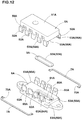
- Figure 12 is an assembling perspective diagram of the case 2 and the diaphragm 3A.
- the first frame 5A has the first concave portion 50A, a first frame main body 51A opposed to the second frame 6A, and first arm portions 52A for holding the second frame 6 in a retained state.
- the first concave portion 50A is formed in an inner end face of the first frame main body 51A which face is opposed to the second frame 6A.
- the first arm portions 52A are disposed along an outer edge of the first frame main body 51A.
- the second frame 6A has a second frame main body 61A opposed to the first frame 5A, and second arm portions 62A for holding the first frame 5A in a retained state.
- the second frame main body 61A is provided in the inner end face opposed to the first frame 5A with the second concave portion 60A.
- the second arm portions 62A are disposed along an outer edge of the second frame main body 61A.
- the second frame 6A is held in the retained state. Further, by the frictional force occurring between the second arm portions 62A and the first frame 5A, a strong fitted state of the first frame 5A and the second frame 6A is realized.
- the fastener 7A is attached to the first arm portions 52A and the second arm portions 62A from the outside of the case 2A.
- an elastically deformable metallic snap ring is used as the fastener 7A.
- the fastener 7A may be configured to be detachable from the first arm portions 52A and the second arm portions 62A. when the fastener 7A is attached to the first arm portions 52 and the second arm portions 62, the first arm portions 52 and the second arm portions 62 are tightened by the fastener 7A, and the first frame 5A is held in the retained state. Thereby, the first frame 5A and the second frame 6A are fitted with each other and united without fastening screws and screw nuts.
- a pair of the fasteners 7A divided into two are used in consideration of easiness when attached to the first arm portions 52 and the second arm portions 62, but it may be possible to use a single annular fastener.
- the first arm portions 52A are provided with a positional displacement preventing means 53A for maintaining the position of the fastener 7A.
- the positional displacement preventing means 53A comprises a first retaining projection 54A jutting out outwardly of the case 2A on the second frame main body 61A side of the fastener 7A disposed in each of the first arm portions 52A.
- the second arm portions 62A are provided with a positional displacement preventing means 63A for maintaining the position of the fastener 7A.
- the positional displacement preventing means 63A comprises a second retaining projection 64A jutting out outwardly of the case 2A on the first frame main body 51A side of the fastener 7A disposed in each of the second arm portions 62A.
- the fastener 7A biases the first retaining projections 54A toward the tip ends of the first arm portions 52A, and biases the second retaining projections 64A toward the tip ends of the second arm portions 62A as a counteraction.
- the first frame main body 51A and the second frame main body 61A closely contact with each other, and the edge portion 32A of the diaphragm 3A is secured between the first frame main body 51A and the second frame main body 61A in a compressed state. Therefore, the leakage of the fluid being treated at the edge portion 32A of the diaphragm 3A is further suppressed.
- an outer edge of the first frame main body 51A is provided with third concave portions 56A as the positional displacement preventing means 53A.
- an outer edge of the second frame main body 61A is provided with fourth concave portions 66A as the positional displacement preventing means 63A.
- the third concave portions 56A and the fourth concave portions 66A are fitted by protruding portions 70A which are formed at the tip ends of the fastener 7A so as to protrude inwardly.
- the mode of the positional displacement preventing means 53A is not limited to the above described first retaining projections 54A and third concave portions 56A. Any mode may be employed as far as it has a function to maintain the position of the fastener 7A.
- the mode of the positional displacement preventing means 63A is not limited to the above described second retaining projections 64A and fourth concave portions 66A. Any mode may be employed as far as it has a function to maintain the position of the fastener 7A.
- the positional displacement preventing means 53A, 63A may be an annular groove (not shown) extending along the outer edge of the case 2A in the outer circumference surfaces of the first arm portions 52A and the second arm portions 62A.
- Such annular groove can maintain the position of the fastener 7A, and the contact between the first frame main body 51A and the second frame main body 61A is improved by the biasing force caused by the fastener 7A, therefore, the leakage of the fluid being treated from the edge portion 32A of the diaphragm 3A is further suppressed.
- the first arm portions 52A and the second arm portions 62A are alternately disposed along the outer circumference of the case 2A. Thereby, it becomes possible to evenly compress the edge portion 32A of the diaphragm 3A, and the leakage of the fluid being treated from the edge portion 32A of the diaphragm 3A is further suppressed.
- first arm portions 52A and the second arm portions 62A are continuously provided along the outer circumference of the case 2A. Thereby, it becomes possible to evenly compress the edge portion 32A of the diaphragm 3A with sufficient strength, therefore, the leakage of the fluid being treated from the edge portion 32A of the diaphragm 3A is further suppressed.
- fifth concave portions 59A are formed between the adjacent first arm portions 52A of the first frame 5A.
- the fifth concave portion 59A is formed in a stepped shape complementary with the second arm portion 62A of the second frame 6A.
- the fifth concave portions 59A are fitted with the second arm portions 62A of the second frame 6A.
- sixth concave portions 69A are formed between the adjacent second arm portions 62A of the second frame 6A.
- the sixth concave portions 69A are formed in a stepped shape complementary with the first arm portion 52A of the first frame 5A.
- the sixth concave portions 69A are fitted with the first arm portions 52A of the first frame 5A. Thereby, the first frame 5A and the second frame 6A are fitted each other strongly and united. Therefore, the leakage of the fluid being treated from the edge portion 32A of the diaphragm 3A is further suppressed.
- the edge portion 32A of the diaphragm 3A is continuously provided with a thick part 33A whose thickness is more than the membrane portion 31A. Thereby, the durability of the diaphragm 3A is fully secured, and the first frame 5A and the second frame 6A can hold the diaphragm 3A, while exerting an enough pressure to the thick part 33A. Thus, the leakage of the fluid being treated from the edge portion 32A of the diaphragm 3A is further suppressed.
- the second frame 6A is provided with a groove 65A in which the thick part 33A is fitted.
- the method of securing the diaphragm 3A comprises a frame fitting step, a diaphragm holding step, and a fastener attaching step.
- the first concave portion 50A (cf. Figure 9 ) is opposed to the second concave portion 60A across the diaphragm 3A, and the first frame 5A and the second frame 6A are fitted with each other so that the first arm portions 52A and the second arm portions 62A are alternately arranged along the outer edge of the case 2A.
- the edge portion 32A of the diaphragm 3A are compressed and held between the first frame 5A and the second frame 6A.
- the fastener 7A is attached to the first arm portions 52A and the second arm portions 62A from the outside of the case 2A.
- the first arm portions 52A and the second arm portions 62A are constricted by the fastener 7A, and the first frame 5A and the second frame 6A are held in the retained state. Therefore, it is possible to achieve a state in which the first frame 5A and the second frame 6A are firmly fitted with each other, and the first frame 5A and the second frame 6A are strongly united.
- valve device according to the present invention, the present invention can be embodied in various forms without being limited to the illustrated embodiments.
Landscapes
- Engineering & Computer Science (AREA)
- General Engineering & Computer Science (AREA)
- Mechanical Engineering (AREA)
- Physics & Mathematics (AREA)
- Fluid Mechanics (AREA)
- Reciprocating Pumps (AREA)
- Sealing Devices (AREA)
- Diaphragms And Bellows (AREA)
Abstract
Description
- The present invention relates to a structure for securing a diaphragm which divides a space into a first chest and a second chest, to a case which forms the space therein, a diaphragm pump and a valve device which are equipped with the same, and a method of securing a diaphragm.
- In various analyses such as chemical examination, environmental analyses and biotechnological research, a diaphragm pump and a valve device which are equipped with a diaphragm are employed in order to feed an accurate quantity of a fluid being treated.
For example,Patent document 1 discloses a diaphragm pump having a structure such that a diaphragm is secured between a pair of frames, wherein the frames are mutually-coupled by the use of pairs of screws and screw nuts in order to suppress a leakage of the fluid from an edge portion of the diaphragm. - Patent document 1: Japanese Patent Application Publication No.
H11-183359 - The leakage of the fluid is caused when the force of the paired frames pressing the diaphragm becomes insufficient locally or overall. Therefore, in the structure for securing the diaphragm, a large number of screws and nuts are used in order to press the diaphragm evenly by a sufficient force.
- In the structure for securing the diaphragm, however, since the number of the parts increases, this becomes a limiting factor of cost-cutting of the diaphragm pump and the valve device. Further, the work of fastening the screws and nuts is time-consuming, and forces the worker to bear the burden, and a man-hour required for assembling the diaphragm pump and the valve device is increased.
- In view of the circumstances as described above, the present invention was made, and a primary object is to provide a structure for securing a diaphragm and others capable of achieving a cost-cutting by reducing the number of parts and making the assembling easy.
- The present invention is a structure for securing a diaphragm which divides a space into a first chest and a second chest, to a case which forms the space therein,
characterized in that
the case has a first frame having a first concave portion defining the first chest, and a second frame having a second concave portion defining the second chest,
the first frame has a first frame main body opposed to the second frame, and first arm portions disposed intermittently along an outer edge of the first frame main body and extending toward the second frame,
the second frame has a second frame main body opposed to the first frame, and second arm portions disposed intermittently along an outer edge of the second frame main body and extending toward the first frame, and
an edge portion of the diaphragm is compressed and secured between the first frame and the second frame which are fitted with each other, and
characterized by further comprising
a fastener for constricting the first arm portions and the second arm portions from the outer side of the case. - In the valve device according to the present invention, it is desirable that the first arm portions and the second arm portions are provided with a positional displacement preventing means to maintain the position of the fastener.
- In the valve device according to the present invention, it is desirable that the positional displacement preventing means comprises
a first retaining projection disposed on each of the first arm portions and jutting out outwardly of the case on the second frame main body side of the fastener, and
a second retaining projection disposed on each of the second arm portions and jutting out outwardly of the case on the first frame main body side of the fastener. - In the valve device according to the present invention, it is desirable that the positional displacement preventing means is an annular groove extending along an outer edge of the case in the outer circumference surfaces of the first arm portions and the second arm portions.
- In the valve device according to the present invention, it is desirable that the first arm portions and the second arm portions are alternately dispersed along the outer edge of the case.
- In the valve device according to the present invention, it is desirable that the first arm portions and the second arm portions are continuously provided along the outer circumference of the case.
- In the valve device according to the present invention, it is desirable that
the edge portion of the diaphragm is provided with a thick part having a larger thickness. - In the valve device according to the present invention, it is desirable that the first frame and/or the second frame are provided with a positioning groove at which the thick part is disposed.
- The present invention is a diaphragm pump equipped with the structure for securing a diaphragm as set forth in any one of claims 1-8 and characterized in that
the first frame is provided with a first port communicating with the first chest,
the second frame is provided with a second port communicating with the second chest,
a fluid for driving the diaphragm is fed to the first chest via the first port, and
a fluid being treated flows in and flows out of the second chest via the second port. - The present invention is a valve device equipped with the structure for securing a diaphragm as set forth in claims 1-8, and characterized in that
the first chest of the first frame is provided with a driving means for driving the diaphragm,
the second frame has an inflow port for allowing the fluid to flow into the second chest, and an outflow port for allowing the fluid to flow out of the second chest,
the outflow port has an opening around which a valve seat is formed, and
the diaphragm sits on and leaves the valve seat to close and open the outflow port. - The present invention is a method for securing a diaphragm which divides a space into a first chest and a second chest, to a case which forms the space therein,
characterized in that
the case has a first frame having a first concave portion defining the first chest, and a second frame having a second concave portion defining the second chest,
the first frame has a first frame main body opposed to the second frame, and first arm portions disposed intermittently along an outer edge of the first frame main body and extending toward the second frame, and
the second frame has a second frame main body opposed to the first frame, and second arm portions disposed intermittently along an outer edge of the second frame main body and extending toward the first frame, and
characterized by comprising
a fitting step of fitting the first frame with the second frame,
a diaphragm holding step of compressing and folding an edge portion of the diaphragm between the first frame and the second frame, and
a fastener attaching step of constricting the first frame and the second frame by attaching a fastener to the first arm portions and the second arm portions from the outside of the case. - The present invention is the diaphragm securing structure for securing the diaphragm which divides the space into the first chest and the second chest, to the case which forms the space therein, wherein the case has the first frame having the first concave portion defining the first chest, and the second frame having the second concave portion defining the second chest, and the edge portion of the diaphragm is compressed and held between the first frame and the second frame which are fitted with each other, whereby the fluid being treated is suppressed from leaking from the edge portion of the diaphragm.
- The first frame has the first frame main body opposed to the second frame, and the first arm portions disposed intermittently along the outer edge of the first frame main body and extending toward the second frame, and the second frame has the second frame main body opposed to the first frame, and the second arm portions disposed intermittently along the outer edge of the second frame main body and extending toward the first frame. Further, the structure for securing a diaphragm comprises the fastener for constricting the first arm portions and the second arm portions from the outside of the case, therefore, it is possible to achieve a state in which the first frame and the second frame are firmly fitted with each other. Thus, it becomes possible to reduce the number of parts used in the structure for securing the diaphragm, making the assembling easy, to achieve the cost-cutting.
- The diaphragm pump according to the present invention has the structure for securing a diaphragm, wherein the fluid for driving the diaphragm is fed to the first chest of the first frame via the first port, and the fluid being treated flows in and flows out of the second chest via the second port. Thereby, although the diaphragm pump has the simple and inexpensive structure, it is possible to feed an accurate quantity of the fluid being treated.
- The valve device according to the present invention has the structure for securing a diaphragm, wherein the first chest of the first frame is provided with the driving means for driving the diaphragm, the second frame has the inflow port for allowing the fluid to flow into the second chest, and the outflow port for allowing the fluid to flow out of the second chest, the outflow port has the opening around which the valve seat is formed, and the diaphragm sits on and leaves the valve seat to close and open the outflow port. Thereby, although the valve device has the simple and inexpensive structure, it is possible to feed an accurate quantity of the fluid being treated.
- The method of securing a diaphragm according to the present invention comprises the frame fitting step of fitting the first frame and the second frame with each other. Thereby, the first frame and the second frame are firmly fitted with each other with sufficient strength. The securing method further comprises the diaphragm holding step of compressing and folding the edge portion of the diaphragm between the first frame and the second frame, therefore, the fluid being treated can be suppressed from leaking from the edge portion of the diaphragm. The securing method further comprises the fastener attaching step of constricting the first frame and the second frame by attaching the fastener from the outside of the case to achieve a strong fitting state, therefore, the first frame and the second frame are firmly united and the leakage of the fluid being treated from the edge portion of the diaphragm can be further suppressed.
-
- [
Figure 1 ] A diagram showing a part of the structure of an analyzing device equipped with a diaphragm pump as an embodiment of the present invention. - [
Figure 2 ] A perspective view of the diaphragm pump shown inFigure 1 . - [
Figure 3 ] A plan view of the diaphragm pump shown inFigure 2 . - [
Figure 4 ] A cross sectional view of the diaphragm shown inFigure 3 taken along line A-A. - [
Figure 5 ] A cross sectional view of the diaphragm shown inFigure 3 taken along line B-B. - [
Figure 6 ] An assembling perspective diagram of the diaphragm pump shown inFigure 2 . - [
Figure 7 ] A perspective view of the first or second case shown inFigure 6 . - [
Figure 8 ] A cross sectional view of the diaphragm shown inFigure 6 . - [
Figure 9 ] A cross sectional view showing the structure of a valve device as another embodiment of the present invention. - [
Figure 10 ] A cross sectional view showing a state of the valve device shown inFigure 9 in which the solenoidal coil is energized. - [
Figure 11 ] A perspective view of the case shown inFigure 9 . - [
Figure 12 ] An assembling perspective diagram of the case shown inFigure 11 . - Embodiments of the present invention will be described hereunder in conjunction with drawings.
-
Figure 1 shows a general structure of adiaphragm pump 1 as a first embodiment of the present invention. - The
diaphragm pump 1 is to feed a fluid being treated such as test sample at a constant quantity.
Thediaphragm pump 1 has acase 2 forming aspace 20 therein, and adiaphragm 3 dividing thespace 20 into afirst chest 21 and asecond chest 22.
By filling up thefirst chest 21 with a fluid such as gas and discharging the fluid, the fluid being treated is fed from thesecond chest 22. - Namely, by the gas filling up the
first chest 21 and discharged therefrom, thediaphragm 3 is driven and transformed, and the fluid is fed from thesecond chest 22 at a constant quantity.
The volume of the discharged fluid is determined by the volume of thespace 20, the volume of thediaphragm 3 occupying thespace 20 and the like. - In
Figures 2 and3 , the external appearance of thediaphragm pump 1 is shown.
InFigure 4 andFigure 5 , there are shown the A-A line section and B-B line section of thediaphragm pump 1 shown inFigure 3 . InFigure 6 , there is shown an assembly perspective diagram of thediaphragm pump 1. - The
diaphragm 3 is secured to thecase 2 by a securingstructure 4. - The
case 2 of thediaphragm pump 1 has afirst frame 5 having a firstconcave portion 50 and asecond frame 6 having a secondconcave portion 60.
Thefirst frame 5 and thesecond frame 6 fitted with each other achieve a stiff fitted state by afastener 7.
The firstconcave portion 50 forms aspace 20a on thefirst chest 21 side.
The secondconcave portion 60 forms aspace 20b on thesecond chest 22 side.
The firstconcave portion 50 is opposed to the secondconcave portion 60.
The firstconcave portion 50 and the secondconcave portion 60 are formed in the form of an earthenware mortar. - The materials of the
first frame 5 and thesecond frame 6 are determined in consideration of chemical resistance and the like. For example, PP(polypropylene), POM(polyacetal), PEEK(polyether ether ketone), PPS(polyphenylene sulfide), PTFE(polytetrafluoroethylene) or the like is used.
In this embodiment, thefirst frame 5 and thesecond frame 6 are mechanically united by fitting without using adhesive, therefore, materials of poor adhesiveness can be used, and the freedom of choice of material is increased. - As shown in
Figures 4 and5 , thediaphragm 3 has amembrane portion 31 dividing thespace 20 into thefirst chest 21 and thesecond chest 22, and anedge portion 32 formed at the outer peripheral edge of themembrane portion 31.
Theedge portion 32 is secured between thefirst frame 5 and thesecond frame 6.
By the elastic deformation of themembrane portion 31, thefirst chest 21 and thesecond chest 22 are alternately increased and decreased in their volumes. - The
edge portion 32 of thediaphragm 3 is compressed and held between thefirst frame 5 and thesecond frame 6 which are fitted with each other. Thereby, the fluid being treated is suppressed from leaking from theedge portion 32 of thediaphragm 3. - The
diaphragm 3 is formed from an elastic material which comprises, as the rubber component, at least one of Ethylene Propylene Diene (EPDM), fluoro rubber(FKM, FPM, FFKM), hydrogenated nitrile rubber (HNBR), butylene rubber (IIR) and silicone rubber(VMQ) for example.
If a rubber material including double bonds in its polymer main chain is used, there is a possibility that, during long-time use, the polymer main chain is broken, and it becomes impossible to maintain the durability of thediaphragm 3.
In particular, Ethylene Propylene Diene (EPDM) is preferred as the rubber component from the point of view of gas barrier, heat resistance, chemical resistance and production cost. -
Figure 7 shows thefirst frame 5.
As shown inFigures 2 ,3 ,5 ,7 etc., thefirst frame 5 has the firstconcave portion 50, a first framemain body 51 opposed to thesecond frame 6, andfirst arm portions 52 for holding thesecond frame 6 in a retained state.
The firstconcave portion 50 is formed in an inner end face of the first framemain body 51 which face is opposed to thesecond frame 6 across the diaphragm.
The first framemain body 51 is generally column-shaped.
Thefirst arm portions 52 are disposed intermittently along an outer edge of the first framemain body 51. - In this embodiment, the
first frame 5 and thesecond frame 6 are formed in the identical shape as shown inFigures 6 and7 . Accordingly, thefirst frame 5 and thesecond frame 6 can be manufactured by the use of the same mold, and the production cost of thediaphragm pump 1 can be reduced. - The
second frame 6 has a second framemain body 61 opposed to thefirst frame 5, andsecond arm portions 62 for holding thefirst frame 5 in a retained state.
The secondconcave portion 60 is formed in an inner end face of the second framemain body 61 which face is opposed to thefirst frame 5.
The second framemain body 61 is generally column-shaped.
Thesecond arm portions 62 are disposed intermittently along the outer edge of the second framemain body 61. - By the frictional force occurring between the
first arm portions 52 and thesecond frame 6 when thefirst frame 5 and thesecond frame 6 are fitted with each other, thesecond frame 6 is held in the retained state.
Further, by the frictional force occurring between thesecond arm portions 62 and thefirst frame 5, a strong fitted state of thefirst frame 5 and thesecond frame 6 is realized. - The
fastener 7 is attached to thefirst arm portions 52 and thesecond arm portions 62 from the outside of thecase 2. In this embodiment, as thefastener 7, an elastically deformable metallic snap ring is used.
Thefastener 7 may be configured to be detachable from thefirst arm portions 52 and thesecond arm portions 62.
when thefastener 7 is attached to thefirst arm portions 52 and thesecond arm portions 62, thefirst arm portions 52 and thesecond arm portions 62 are tightened by thefastener 7, and thefirst frame 5 is held in the retained state.
Thereby, thefirst frame 5 and thesecond frame 6 are fitted with each other and united without fastening screws and screw nuts. Therefore, it becomes possible to reduce the number of parts used in thestructure 4 for securing thediaphragm 3, making the assembling easy, to achieve the cost-cutting. Further, it becomes possible to make the structure of thediaphragm pump 1 simple and inexpensive. - The
first arm portions 52 are provided with a positionaldisplacement preventing means 53 to maintain the position of thefastener 7.
The positionaldisplacement preventing means 53 comprises afirst retaining projection 54 jutting out outwardly of thecase 2 on the second framemain body 61 side of thefastener 7 disposed in eachfirst arm portion 52.
By being provided in thefirst arm portion 52 with thefirst retaining projection 54, the outside of thefirst arm portion 52 is stepped. The inside of thefirst arm portions 52 is also stepped. - Similarly, the
second arm portions 62 are provided with a positionaldisplacement preventing means 63 to maintain the position of thefastener 7.
The positionaldisplacement preventing means 63 comprises asecond retaining projection 64 jutting out outwardly of thecase 2 on the first framemain body 51 side of thefastener 7 disposed in eachsecond arm portion 62.
By being provided in thesecond arm portion 62 with thesecond retaining projection 64, the outside of thesecond arm portion 62 is stepped. The inside of thesecond arm portions 62 is also stepped. - when the
fastener 7 is attached to thecase 2, thefastener 7 biases thefirst retaining projection 54 toward the tip end of thefirst arm portion 52, and biases thesecond retaining projection 64 toward the tip end of thesecond arm portion 62. Thereby, the first framemain body 51 and the second framemain body 61 are closely contacted with each other, and theedge portion 32 of thediaphragm 3 is secured between the first framemain body 51 and the second framemain body 61 in a compressed state. Therefore, the fluid being treated is further suppressed from leaking from theedge portion 32 of thediaphragm 3. - The modes of the positional
displacement preventing means projection 54 and thesecond retaining projection 64. Any mode which functions to maintain the position of thefastener 7 may be employed. For example, the positionaldisplacement preventing means case 2 in the outer circumference surface of thefirst arm portions 52 and thesecond arm portions 62.
By the annular groove, the position of thefastener 7 is maintained, and the contact of the first framemain body 51 with the second framemain body 61 is improved by the biasing force caused by thefastener 7, therefore, the leakage of the fluid being treated from theedge portion 32 of thediaphragm 3 is further suppressed. - As shown in
Figures 4 and7 , thefirst frame 5 is provided with afirst port 57 communicating with thefirst chest 21. Thefirst port 57 is provided at the tip end with anipple 58 for connecting a pipe (not shown).
Through thefirst port 57 and the pipe, gas for driving thediaphragm 3 flows in and flows out of thefirst chest 21.
Thefirst arm portions 52 are formed not to interfere thenipple 58. - In this embodiment, the
first port 57 extends along the end face of the column-shapedfirst frame 5 and communicates with thenipple 58 formed on the side surface. But, thefirst port 57 may be configured so as to extend toward the end face of the column-shapedfirst frame 5. In this case, thenipple 58 is formed on the end face of thefirst frame 5. - As shown in
Figures 4 and7 , thesecond frame 6 is provided with asecond port 67 communicating with thesecond chest 22. Thesecond port 67 is provided at the tip end with anipple 68 for connecting a pipe (not shown).
Through thesecond port 67 and the pipe, the fluid being treated flows in and flows out of thesecond chest 22.
Incidentally, thesecond arm portions 62 are formed not to interfere thenipple 68.
Thefirst frame 5 and thesecond frame 6 are fitted with each other so that thenipple 58 overlaps thenipple 68 in a plan view. - In this embodiment, the
second port 67 extends along the end face of the column-shapedsecond frame 6, and communicates with thenipple 68 formed on the side surface. But, thesecond port 67 may be configured so as to extend toward the end face of the column-shapedsecond frame 6. In this case, thenipple 68 is formed on the end face of thesecond frame 6. - As shown in
Figures 2 and6 , thefirst arm portions 52 and thesecond arm portions 62 are alternately disposed along the outer circumference of thecase 2. Thereby, it becomes possible to evenly compress theedge portion 32 of thediaphragm 3, and the fluid being treated is further suppressed from leaking from theedge portion 32 of thediaphragm 3. - Further, in this embodiment, the
first arm portions 52 and thearm portions 62 are continuously provided along the outer circumference of thecase 2. Thereby, it becomes possible to evenly compress theedge portion 32 of thediaphragm 3 with sufficient strength, and the leakage of the fluid being treated from theedge portion 32 of thediaphragm 3 is further suppressed. - As shown in
Figures 6 and7 , between the adjacentfirst arm portions 52 of thefirst frame 5, thirdconcave portions 59 are provided. The thirdconcave portion 59 is formed in a stepped shape complementary with thesecond arm portion 62 of thesecond frame 6. The thirdconcave portions 59 fit with thesecond arm portions 62 of thesecond frame 6. By the fitting, thefirst frame 5 and thesecond frame 6 are more strongly fitted with each other and united. Therefore, the leakage of the fluid being treated from theedge portion 32 of thediaphragm 3 is further suppressed. - Between the adjacent
second arm portions 62 of thesecond frame 6, on the other hand, fourthconcave portions 69 are provided. The fourthconcave portion 69 is formed in a stepped shape complementary with thefirst arm portion 52 of thefirst frame 5. The fourthconcave portions 69 fit with thefirst arm portions 52 of thefirst frame 5. Thereby, thefirst frame 5 and thesecond frame 6 are more strongly fitted with each other and united. Therefore, the leakage of the fluid being treated from theedge portion 32 of thediaphragm 3 is further suppressed. -
Figure 8 shows the A-A line section of thediaphragm 3. In theedge portion 32 of thediaphragm 3, athick part 33 whose thickness is more than that of themembrane portion 31 is continuously formed. Thereby, thefirst frame 5 and thesecond frame 6 can hold thediaphragm 3 by exerting enough pressure to thethick part 33, while securing sufficient durability for thediaphragm 3, and the leakage of the fluid being treated from theedge portion 32 of thediaphragm 3 is further suppressed. - As shown in
Figure 7 , thefirst frame 5 is provided with agroove 55 in which thethick part 33 fits.
Similarly, thesecond frame 6 is provided with agroove 65 in which thethick part 33 fits.
The total of the depths of thegroove 55 and thegroove 65 is set to be smaller than the thickness of thethick part 33.
By thegrooves thick part 33 is moderately compressed, and the leakage of the fluid being treated from theedge portion 32 of thediaphragm 3 is further suppressed.
When assembling thediaphragm 3 in the inside of thefirst frame 5 and thesecond frame 6, thegrooves diaphragm pump 1. - Hereinafter, a method of securing the
diaphragm 3 to thecase 2 in this embodiment will be described with reference toFigure 6 .
The method of securing the diaphragm comprises a frame fitting step, a diaphragm holding step, and a fastener attaching step. - In the frame fitting step, the first concave portion 50 (cf.
Figure 5 ) and the secondconcave portion 60 are opposed to each other across thediaphragm 3, and
thefirst frame 5 and thesecond frame 6 are fitted with each other so that thefirst arm portions 52 and thearm portions 62 are arranged alternately along the outer edge of thecase 2. - In the diaphragm holding step, the
edge portion 32 of thediaphragm 3 is compressed and held between thefirst frame 5 and thesecond frame 6. - In the subsequent fastener attaching step, the
fastener 7 is attached to thefirst arm portions 52 and thesecond arm portions 62 from the outside of thecase 2.
Thereby, thefirst arm portions 52 and thesecond arm portions 62 are tightened by thefastener 7. Thus, the strong fitted state of thefirst frame 5 and thesecond frame 6 is realized, and thefirst frame 5 and thesecond frame 6 are strongly united. -
Figure 9 shows a valve device as a second embodiment of the present invention.
Thevalve device 8 has acase 2A forming aspace 20A therein, and adiaphragm 3A dividing thespace 20A into afirst chest 21A and asecond chest 22A.
Thediaphragm 3A is secured to thecase 2A by a securingstructure 4A. - The
case 2A has afirst frame 5A having a firstconcave portion 50A, and asecond frame 6A having a secondconcave portion 60A. The firstconcave portion 50A forms a space on thefirst chest 21A side. The secondconcave portion 60A forms a space on thesecond chest 22A side. - The
diaphragm 3A has amembrane portion 31A dividing thespace 20A into thefirst chest 21A and thesecond chest 22A, and anedge portion 32A formed at the outer peripheral edge of themembrane portion 31A.
Theedge portion 32A is secured between thefirst frame 5A and thesecond frame 6A.
By the elastic deformation of themembrane portion 31A, thediaphragm 3A can make oscillating movements. - The
edge portion 32A of thediaphragm 3A is compressed and held between thefirst frame 5A and thesecond frame 6A which are fitted with each other. Thereby, the leakage of the fluid being treated from theedge portion 32A of thediaphragm 3A is suppressed. - The materials of the
first frame 5A and thesecond frame 6A are the same as those of thefirst frame 5 and thesecond frame 6 in the first embodiment.
The material of thediaphragm 3A is the same as that of thediaphragm 3 in the first embodiment. - The first
concave portion 50A of thefirst frame 5A, namely, thefirst chest 21A is provided with a driving means 80 for driving thediaphragm 3A.
Thediaphragm 3A is oscillated by being driven by the driving means 80. - The driving means 80 has an oscillating
member 81 oscillating integrally with thediaphragm 3A, a first plunger (moving core) 82 for pressing one end of the oscillatingmember 81, asecond plunger 83 for pressing the other end of the oscillatingmember 81 and the like.
The oscillatingmember 81 is housed in thespace 20A.
The oscillatingmember 81 is freely turnably supported by theshaft member 81a.
Both ends of theshaft member 81a are supposed by thefirst frame 5A. - The
first plunger 82 is driven by a firstcoiled spring 84, asolenoidal coil 85 and a fixediron core 86, and transmits its driving force to the oscillatingmember 81.
Thesecond plunger 83 is driven by a secondcoiled spring 87, and transmits its driving force to the oscillatingmember 81. The spring load of the firstcoiled spring 84 is set to be more than the spring load of the secondcoiled spring 87.
The oscillatingmember 81 and thediaphragm 3A receive the driving force transmitted by thefirst plunger 82 and thesecond plunger 83, and they are turned around theshaft member 81a like a seesaw. - The
second frame 6A has an inflow port (Common port) 71 for flowing the fluid into thesecond chest 22A, and a NC (Normally Close)outflow port 72 and NO (Normally Open)outflow port 73 for flowing the fluid out of thesecond chest 22A.
TheNC outflow port 72 has anopening 72b around which avalve seat 72a is formed. Thediaphragm 3A sits on and leaves thevalve seat 72a to close and open theNC outflow port 72.
TheNO outflow port 73 has anopening 73b around which avalve seat 73a is formed. Thediaphragm 3A sits on and leaves thevalve seat 73a to close and open theNO outflow port 73.
By the turning of the oscillatingmember 81, either one of theNC outflow port 72 and theNO outflow port 73 is closed, and the other is opened. Thereby, the ports are alternately opened and closed.
In this embodiment, thevalve device 8 is so called electromagnetic valve to switch the flow paths such that, by the electromagnetic force caused by thesolenoidal coil 85 of the driving means 80, thediaphragm 3A is actuated to open and close theNC outflow port 72 and theNO outflow port 73. - Hereinafter, the opening-closing action of the
valve device 8 will be described. - The
inflow port 71 is always opened, and the fluid is fed into thesecond chest 22A through theinflow port 71.
As previously mentioned, since the spring load of the firstcoiled spring 84 is larger than the spring load of the secondcoiled spring 87, an elastomeric force generated by the firstcoiled spring 84 is larger than an elastomeric force generated by the secondcoiled spring 87.
At normal times, therefore, as shown inFigure 9 , the oscillatingmember 81 and thediaphragm 3A maintain such a posture that they are turned counterclockwise in the figure, wherein theNC outflow port 72 is closed, and theNO outflow port 73 is opened.
Thereby, the fluid flowing into thesecond chest 22A from theinflow port 71 is discharged from theNO outflow port 73 as indicated by arrow (A). -
Figure 10 shows thevalve device 8 in a state such that thesolenoidal coil 85 is energized.
when a predetermined electric current flows through thesolenoidal coil 85, the electromagnetic force thereof moves thefirst plunger 82 toward a direction to compress the firstcoiled spring 84. At this moment, thesecond plunger 83 presses the oscillatingmember 81, therefore, the oscillatingmember 81 and thediaphragm 3A are turned clockwise, and theNO outflow port 73 is closed, and theNC outflow port 72 is opened.
Thereby, the fluid flowing into thesecond chest 22A from theinflow port 71 as indicated by arrow B is discharged from theNC outflow port 72. -
Figure 11 is a perspective view of thecase 2A which thevalve device 8 is equipped with.
Figure 12 is an assembling perspective diagram of thecase 2 and thediaphragm 3A.
Thefirst frame 5A has the firstconcave portion 50A, a first framemain body 51A opposed to thesecond frame 6A, andfirst arm portions 52A for holding thesecond frame 6 in a retained state.
As shown inFigure 9 , the firstconcave portion 50A is formed in an inner end face of the first framemain body 51A which face is opposed to thesecond frame 6A.
Thefirst arm portions 52A are disposed along an outer edge of the first framemain body 51A.
Thesecond frame 6A has a second framemain body 61A opposed to thefirst frame 5A, andsecond arm portions 62A for holding thefirst frame 5A in a retained state.
The second framemain body 61A is provided in the inner end face opposed to thefirst frame 5A with the secondconcave portion 60A.
Thesecond arm portions 62A are disposed along an outer edge of the second framemain body 61A. - By the frictional force occurring between the
first arm portions 52A and thesecond frame 6A when thefirst frame 5A and thesecond frame 6A are fitted with each other, thesecond frame 6A is held in the retained state.
Further, by the frictional force occurring between thesecond arm portions 62A and thefirst frame 5A, a strong fitted state of thefirst frame 5A and thesecond frame 6A is realized. - The
fastener 7A is attached to thefirst arm portions 52A and thesecond arm portions 62A from the outside of thecase 2A. In this embodiment, as thefastener 7A, an elastically deformable metallic snap ring is used.
Thefastener 7A may be configured to be detachable from thefirst arm portions 52A and thesecond arm portions 62A.
when thefastener 7A is attached to thefirst arm portions 52 and thesecond arm portions 62, thefirst arm portions 52 and thesecond arm portions 62 are tightened by thefastener 7A, and thefirst frame 5A is held in the retained state.
Thereby, thefirst frame 5A and thesecond frame 6A are fitted with each other and united without fastening screws and screw nuts. Therefore, it becomes possible to reduce the number of parts used in thestructure 4A for securing thediaphragm 3A, making the assembling easy, to achieve the cost-cutting. Further, it becomes possible to make the structure of thevalve device 8 simple and inexpensive.
In this embodiment, a pair of thefasteners 7A divided into two are used in consideration of easiness when attached to thefirst arm portions 52 and thesecond arm portions 62, but it may be possible to use a single annular fastener. - The
first arm portions 52A are provided with a positional displacement preventing means 53A for maintaining the position of thefastener 7A.
The positional displacement preventing means 53A comprises afirst retaining projection 54A jutting out outwardly of thecase 2A on the second framemain body 61A side of thefastener 7A disposed in each of thefirst arm portions 52A.
By being provided in thefirst arm portion 52A with thefirst retaining projection 54A, the outside of thefirst arm portion 52A is stepped. The inside of thefirst arm portions 52A is also stepped. - Similarly, the
second arm portions 62A are provided with a positional displacement preventing means 63A for maintaining the position of thefastener 7A.
The positional displacement preventing means 63A comprises asecond retaining projection 64A jutting out outwardly of thecase 2A on the first framemain body 51A side of thefastener 7A disposed in each of thesecond arm portions 62A.
By being provided in thesecond arm portion 62A with thesecond retaining projection 64A, the outside of thesecond arm portion 62A is stepped. The inside of thesecond arm portions 62A is also stepped. - when the
fastener 7A is attached to thecase 2A, thefastener 7A biases thefirst retaining projections 54A toward the tip ends of thefirst arm portions 52A, and biases thesecond retaining projections 64A toward the tip ends of thesecond arm portions 62A as a counteraction.
Thereby, the first framemain body 51A and the second framemain body 61A closely contact with each other, and theedge portion 32A of thediaphragm 3A is secured between the first framemain body 51A and the second framemain body 61A in a compressed state. Therefore, the leakage of the fluid being treated at theedge portion 32A of thediaphragm 3A is further suppressed. - In this embodiment, as shown in
Figure 12 , an outer edge of the first framemain body 51A is provided with thirdconcave portions 56A as the positional displacement preventing means 53A. Similarly, an outer edge of the second framemain body 61A is provided with fourthconcave portions 66A as the positional displacement preventing means 63A.
The thirdconcave portions 56A and the fourthconcave portions 66A are fitted by protrudingportions 70A which are formed at the tip ends of thefastener 7A so as to protrude inwardly.
By the fitting of the protrudingportions 70A to the thirdconcave portion 56A and the fourthconcave portion 66A, the positional displacement and coming off of thefastener 7A can be prevented. - The mode of the positional displacement preventing means 53A is not limited to the above described first retaining
projections 54A and thirdconcave portions 56A. Any mode may be employed as far as it has a function to maintain the position of thefastener 7A.
Similarly, the mode of the positional displacement preventing means 63A is not limited to the above describedsecond retaining projections 64A and fourthconcave portions 66A. Any mode may be employed as far as it has a function to maintain the position of thefastener 7A.
For example, the positional displacement preventing means 53A, 63A may be an annular groove (not shown) extending along the outer edge of thecase 2A in the outer circumference surfaces of thefirst arm portions 52A and thesecond arm portions 62A.
Such annular groove can maintain the position of thefastener 7A, and the contact between the first framemain body 51A and the second framemain body 61A is improved by the biasing force caused by thefastener 7A, therefore, the leakage of the fluid being treated from theedge portion 32A of thediaphragm 3A is further suppressed. - The
first arm portions 52A and thesecond arm portions 62A are alternately disposed along the outer circumference of thecase 2A. Thereby, it becomes possible to evenly compress theedge portion 32A of thediaphragm 3A, and the leakage of the fluid being treated from theedge portion 32A of thediaphragm 3A is further suppressed. - Further, in this embodiment, the
first arm portions 52A and thesecond arm portions 62A are continuously provided along the outer circumference of thecase 2A. Thereby, it becomes possible to evenly compress theedge portion 32A of thediaphragm 3A with sufficient strength, therefore, the leakage of the fluid being treated from theedge portion 32A of thediaphragm 3A is further suppressed. - Between the adjacent
first arm portions 52A of thefirst frame 5A, fifthconcave portions 59A are formed. The fifthconcave portion 59A is formed in a stepped shape complementary with thesecond arm portion 62A of thesecond frame 6A.
The fifthconcave portions 59A are fitted with thesecond arm portions 62A of thesecond frame 6A.
Thereby, thefirst frame 5A and thesecond frame 6A are strongly fitted with each other and united. Therefore, the leakage of the fluid being treated from theedge portion 32A of thediaphragm 3A is further suppressed. - Between the adjacent
second arm portions 62A of thesecond frame 6A, on the other hand, sixthconcave portions 69A are formed. The sixthconcave portions 69A are formed in a stepped shape complementary with thefirst arm portion 52A of thefirst frame 5A.
The sixthconcave portions 69A are fitted with thefirst arm portions 52A of thefirst frame 5A. Thereby, thefirst frame 5A and thesecond frame 6A are fitted each other strongly and united. Therefore, the leakage of the fluid being treated from theedge portion 32A of thediaphragm 3A is further suppressed. - The
edge portion 32A of thediaphragm 3A is continuously provided with athick part 33A whose thickness is more than themembrane portion 31A. Thereby, the durability of thediaphragm 3A is fully secured, and thefirst frame 5A and thesecond frame 6A can hold thediaphragm 3A, while exerting an enough pressure to thethick part 33A. Thus, the leakage of the fluid being treated from theedge portion 32A of thediaphragm 3A is further suppressed. - The
second frame 6A is provided with agroove 65A in which thethick part 33A is fitted. - Hereinafter, a method of securing diaphragm (A) which is to secure the
diaphragm 3A to thecase 2A in this embodiment, will be described with reference toFigure 11 .
The method of securing thediaphragm 3A comprises a frame fitting step, a diaphragm holding step, and a fastener attaching step. - In the frame fitting step, the first
concave portion 50A (cf.Figure 9 ) is opposed to the secondconcave portion 60A across thediaphragm 3A, and
thefirst frame 5A and thesecond frame 6A are fitted with each other so that thefirst arm portions 52A and thesecond arm portions 62A are alternately arranged along the outer edge of thecase 2A. - In the diaphragm holding step, the
edge portion 32A of thediaphragm 3A are compressed and held between thefirst frame 5A and thesecond frame 6A. - In the subsequent fastener attaching step, the
fastener 7A is attached to thefirst arm portions 52A and thesecond arm portions 62A from the outside of thecase 2A.
Thereby, thefirst arm portions 52A and thesecond arm portions 62A are constricted by thefastener 7A, and thefirst frame 5A and thesecond frame 6A are held in the retained state. Therefore, it is possible to achieve a state in which thefirst frame 5A and thesecond frame 6A are firmly fitted with each other, and thefirst frame 5A and thesecond frame 6A are strongly united. - while detailed description has been made of the valve device according to the present invention, the present invention can be embodied in various forms without being limited to the illustrated embodiments.
-
- 1
- diaphragm pump
- 2
- case
- 3
- diaphragm
- 4
- securing structure
- 5
- first frame
- 6
- second frame
- 7
- fastener
- 8
- valve device
- 20
- space
- 21
- first chest
- 22
- second chest
- 32
- edge portion
- 33
- thick part
- 50
- first concave portion
- 51
- first frame main body
- 52
- first arm portions
- 53
- positional displacement preventing means
- 54
- first retaining projection
- 60
- second concave portion
- 61
- second frame main body
- 62
- second arm portions
- 63
- positional displacement preventing means
- 64
- second retaining projection
- 71
- inflow port
- 72
- NC outflow port
- 73
- NO outflow port
- 80
- driving means
Claims (11)
- A structure for securing a diaphragm which divides a space into a first chest and a second chest, to a case which forms the space therein,
characterized in thatthe case has a first frame having a first concave portion defining the first chest, and a second frame having a second concave portion defining the second chest,the first frame has a first frame main body opposed to the second frame, and first arm portions disposed intermittently along an outer edge of the first frame main body and extending toward the second frame,the second frame has a second frame main body opposed to the first frame, and second arm portions disposed intermittently along an outer edge of the second frame main body and extending toward the first frame,an edge portion of the diaphragm is compressed and held between the first frame and the second frame which are fitted with each other, andcharacterized by further includinga fastener for constricting the first arm portions and the second arm portions from the outside of the case. - The structure for securing a diaphragm as set forth in claim 1,
wherein the first arm portions and the second arm portions are provided with a positional displacement preventing means to maintain the position of the fastener. - The structure for securing a diaphragm as set forth in claim 2, wherein the positional displacement preventing means comprises a first retaining projection disposed on each of the first arm portions and jutting out outwardly of the case on the second frame main body side of the fastener, and
a second retaining projection disposed on each of the second arm portions and jutting out outwardly of the case on the first frame main body side of the fastener. - The structure for securing a diaphragm as set forth in claim 2, wherein the positional displacement preventing means is an annular groove extending along an outer edge of the case in the outer circumference surfaces of the first arm portions and the second arm portions.
- The structure for securing a diaphragm as set forth in any one of claims 1-4, wherein the first arm portions and the second arm portions are alternately dispersed along the outer edge of the case.
- The structure for securing a diaphragm as set forth in any one of claims 1-5, wherein the first arm portions and the second arm portions are continuously provided along the outer circumference of the case.
- The structure for securing a diaphragm as set forth in any one of claims 1-6, wherein the edge portion of the diaphragm is provided with a thick part having a larger thickness.
- The structure for securing a diaphragm as set forth in claim 7, wherein the first frame and/or the second frame is provided with a positioning groove at which the thick part is disposed.
- A diaphragm pump equipped with the structure for securing a diaphragm as set forth in any one of claims 1-8 and characterized in thatthe first frame is provided with a first port communicating with the first chest,the second frame is provided with a second port communicating with the second chest,a fluid for driving the diaphragm is fed to the first chest via the first port, anda fluid being treated flows in and flows out of the second chest via the second port.
- A valve device having the structure for securing a diaphragm as set forth in any one of claims 1-7 and characterized in thatthe first chest of the first frame is provided with a driving means for driving the diaphragm,the second frame has an inflow port for flowing the fluid into the second chest, and an outflow port for flowing the fluid out of the second chest,the outflow port has an opening around which a valve seat is formed, whereinthe diaphragm sits on and leaves the valve seat to close and open the outflow port.
- A method of securing a diaphragm which divides a space into a first chest and a second chest, to a case forming the space therein,
characterized in thatthe case has a first frame having a first concave portion defining the first chest, and a second frame having a second concave portion defining the second chest,the first frame has a first frame main body opposed to the second frame, and first arm portions disposed intermittently along an outer edge of the first frame main body and extending toward the second frame, andthe second frame has a second frame main body opposed to the first frame, and second arm portions disposed intermittently along an outer edge of the second frame main body and extending toward the first frame, andcharacterized by comprisinga fitting step of fitting the first frame with the second frame,a diaphragm holding step of compressing and folding an edge portion of the diaphragm between the first frame and the second frame, anda fastener attaching step of constricting the first frame and the second frame by attaching a fastener to the first arm portions and the second arm portionsfrom the outside of the case.
Applications Claiming Priority (2)
| Application Number | Priority Date | Filing Date | Title |
|---|---|---|---|
| JP2014058750A JP5952848B2 (en) | 2014-03-20 | 2014-03-20 | Diaphragm fixing structure, diaphragm pump and valve device including the same, and diaphragm fixing method |
| PCT/JP2015/051851 WO2015141278A1 (en) | 2014-03-20 | 2015-01-23 | Structure for securing diaphragm, diaphragm pump and valve device provided with said structure, and method for securing diaphragm |
Publications (3)
| Publication Number | Publication Date |
|---|---|
| EP3118492A1 true EP3118492A1 (en) | 2017-01-18 |
| EP3118492A4 EP3118492A4 (en) | 2017-11-01 |
| EP3118492B1 EP3118492B1 (en) | 2021-06-30 |
Family
ID=54144258
Family Applications (1)
| Application Number | Title | Priority Date | Filing Date |
|---|---|---|---|
| EP15764809.8A Active EP3118492B1 (en) | 2014-03-20 | 2015-01-23 | Structure for securing diaphragm, diaphragm pump and valve device provided with said structure, and method for securing diaphragm |
Country Status (6)
| Country | Link |
|---|---|
| US (1) | US10107280B2 (en) |
| EP (1) | EP3118492B1 (en) |
| JP (1) | JP5952848B2 (en) |
| KR (1) | KR102339441B1 (en) |
| CN (1) | CN106062439B (en) |
| WO (1) | WO2015141278A1 (en) |
Families Citing this family (3)
| Publication number | Priority date | Publication date | Assignee | Title |
|---|---|---|---|---|
| US10677238B2 (en) * | 2017-11-08 | 2020-06-09 | Ingersoll-Rand Industrial U.S., Inc. | Filled resin layer separated pump housing |
| CA3152421A1 (en) * | 2019-10-03 | 2021-04-08 | Emmanuel N. ILONGO | Cleaning system for diaphragm pump |
| CN118188430A (en) * | 2024-02-05 | 2024-06-14 | 正星科技股份有限公司 | High-pressure diaphragm compressor membrane head for hydrogen refueling station |
Family Cites Families (18)
| Publication number | Priority date | Publication date | Assignee | Title |
|---|---|---|---|---|
| US2364111A (en) * | 1942-03-20 | 1944-12-05 | John W Tucker | Pump and the like |
| US2445293A (en) * | 1947-01-30 | 1948-07-13 | Flexitallic Gasket Co Inc | Diaphragm pump |
| US3039272A (en) * | 1958-11-13 | 1962-06-19 | Union Carbide Corp | Fluid actuating device |
| JPS4731201Y1 (en) * | 1969-05-13 | 1972-09-19 | ||
| JPS49130266U (en) * | 1973-03-12 | 1974-11-08 | ||
| JPS5338495Y2 (en) * | 1974-10-09 | 1978-09-19 | ||
| US4160433A (en) * | 1978-02-17 | 1979-07-10 | Olson Engineering Inc. | Modulating air control valve |
| US4387788A (en) * | 1982-01-21 | 1983-06-14 | Lectron Products, Inc. | Diaphragm pressure ring for tone generators |
| JPS58165282U (en) * | 1982-04-30 | 1983-11-02 | 藤倉ゴム工業株式会社 | Piston type fluid actuator |
| JPS60155667U (en) * | 1984-03-27 | 1985-10-17 | 株式会社ナブコ | Hydraulic fluid reservoir |
| IT229674Y1 (en) * | 1993-02-26 | 1999-01-29 | Alcatel Dial Face Spa | PIEZOCERAMIC CAPSULE FOR TELEPHONE DEVICES |
| JP3792034B2 (en) | 1997-12-22 | 2006-06-28 | シスメックス株式会社 | Particle analyzer |
| JP3834745B2 (en) | 1999-05-11 | 2006-10-18 | 応研精工株式会社 | Small pump |
| JP2002139161A (en) * | 2000-11-06 | 2002-05-17 | Smc Corp | Two-way valve |
| JP4324906B2 (en) * | 2003-06-26 | 2009-09-02 | 株式会社ニッキ | Pulsating diaphragm fuel pump |
| JP5161703B2 (en) * | 2008-08-26 | 2013-03-13 | シスメックス株式会社 | Reagent preparation device, sample processing device, and reagent preparation method |
| CN103362786B (en) * | 2013-07-12 | 2018-07-13 | 重庆中镭科技有限公司 | A kind of Minitype piezoelectric diaphragm pump |
| JP6014072B2 (en) * | 2014-03-20 | 2016-10-25 | 住友ゴム工業株式会社 | Diaphragm fixing structure, diaphragm pump and valve device including the same |
-
2014
- 2014-03-20 JP JP2014058750A patent/JP5952848B2/en not_active Expired - Fee Related
-
2015
- 2015-01-23 KR KR1020167026674A patent/KR102339441B1/en not_active Expired - Fee Related
- 2015-01-23 US US15/127,258 patent/US10107280B2/en not_active Expired - Fee Related
- 2015-01-23 EP EP15764809.8A patent/EP3118492B1/en active Active
- 2015-01-23 CN CN201580011711.1A patent/CN106062439B/en not_active Expired - Fee Related
- 2015-01-23 WO PCT/JP2015/051851 patent/WO2015141278A1/en not_active Ceased
Also Published As
| Publication number | Publication date |
|---|---|
| WO2015141278A1 (en) | 2015-09-24 |
| EP3118492A4 (en) | 2017-11-01 |
| JP2015183722A (en) | 2015-10-22 |
| CN106062439B (en) | 2018-05-22 |
| KR102339441B1 (en) | 2021-12-14 |
| CN106062439A (en) | 2016-10-26 |
| US20170107981A1 (en) | 2017-04-20 |
| US10107280B2 (en) | 2018-10-23 |
| JP5952848B2 (en) | 2016-07-13 |
| EP3118492B1 (en) | 2021-06-30 |
| KR20160133471A (en) | 2016-11-22 |
Similar Documents
| Publication | Publication Date | Title |
|---|---|---|
| JP6212463B2 (en) | Small solenoid valve | |
| EP3128174B1 (en) | Diaphragm affixation structure, and diaphragm pump and valve device each comprising same | |
| EP3006798B1 (en) | Valve device | |
| KR20170096995A (en) | Capacity control valve | |
| EP3118492B1 (en) | Structure for securing diaphragm, diaphragm pump and valve device provided with said structure, and method for securing diaphragm | |
| WO2005008108B1 (en) | Extended stroke valve and diaphragm | |
| JP2008002511A (en) | Air operated valve | |
| CN112204280A (en) | Pinch valve | |
| CN105814348A (en) | Valve device | |
| US20250075808A1 (en) | Control valve | |
| US8632051B2 (en) | Solenoid | |
| JP4744319B2 (en) | Diaphragm valve | |
| CN109323012B (en) | Slide type three-way electromagnetic valve | |
| CN101208553A (en) | Valve device | |
| US8613425B2 (en) | Valve seal member and valve | |
| EP4417844B1 (en) | Three-way valve | |
| CN112228589B (en) | A valve structure and solenoid valve device | |
| CN108953740B (en) | Electromagnetic valve | |
| JP2015152075A (en) | Diaphragm valve structure and solenoid valve | |
| JP2023037929A (en) | diaphragm valve | |
| US20220221063A1 (en) | Diaphragm Poppet Valve | |
| JP2008144817A (en) | Air operated valve | |
| CN106233054B (en) | Thermostat device | |
| CN217234571U (en) | Electromagnetic valve | |
| CN211344102U (en) | Sealing diaphragm and corresponding three-way valve |
Legal Events
| Date | Code | Title | Description |
|---|---|---|---|
| STAA | Information on the status of an ep patent application or granted ep patent |
Free format text: STATUS: THE INTERNATIONAL PUBLICATION HAS BEEN MADE |
|
| PUAI | Public reference made under article 153(3) epc to a published international application that has entered the european phase |
Free format text: ORIGINAL CODE: 0009012 |
|
| STAA | Information on the status of an ep patent application or granted ep patent |
Free format text: STATUS: REQUEST FOR EXAMINATION WAS MADE |
|
| 17P | Request for examination filed |
Effective date: 20161006 |
|
| AK | Designated contracting states |
Kind code of ref document: A1 Designated state(s): AL AT BE BG CH CY CZ DE DK EE ES FI FR GB GR HR HU IE IS IT LI LT LU LV MC MK MT NL NO PL PT RO RS SE SI SK SM TR |
|
| AX | Request for extension of the european patent |
Extension state: BA ME |
|
| DAX | Request for extension of the european patent (deleted) | ||
| A4 | Supplementary search report drawn up and despatched |
Effective date: 20170929 |
|
| RIC1 | Information provided on ipc code assigned before grant |
Ipc: F04B 43/02 20060101ALI20170925BHEP Ipc: F04B 53/16 20060101ALI20170925BHEP Ipc: F16J 15/52 20060101ALI20170925BHEP Ipc: F16J 3/02 20060101AFI20170925BHEP Ipc: F04B 53/10 20060101ALI20170925BHEP Ipc: F04B 43/00 20060101ALI20170925BHEP Ipc: F16K 7/12 20060101ALI20170925BHEP Ipc: F04B 43/06 20060101ALI20170925BHEP Ipc: F04B 45/04 20060101ALI20170925BHEP |
|
| RIC1 | Information provided on ipc code assigned before grant |
Ipc: F04B 53/16 20060101ALI20201202BHEP Ipc: F16J 15/52 20060101ALI20201202BHEP Ipc: F04B 45/04 20060101ALI20201202BHEP Ipc: F16K 11/04 20060101ALI20201202BHEP Ipc: F16K 31/06 20060101ALI20201202BHEP Ipc: F16K 11/02 20060101ALI20201202BHEP Ipc: F16J 3/02 20060101AFI20201202BHEP Ipc: F04B 43/00 20060101ALI20201202BHEP Ipc: F16K 31/10 20060101ALI20201202BHEP |
|
| GRAP | Despatch of communication of intention to grant a patent |
Free format text: ORIGINAL CODE: EPIDOSNIGR1 |
|
| STAA | Information on the status of an ep patent application or granted ep patent |
Free format text: STATUS: GRANT OF PATENT IS INTENDED |
|
| INTG | Intention to grant announced |
Effective date: 20210118 |
|
| GRAS | Grant fee paid |
Free format text: ORIGINAL CODE: EPIDOSNIGR3 |
|
| GRAA | (expected) grant |
Free format text: ORIGINAL CODE: 0009210 |
|
| STAA | Information on the status of an ep patent application or granted ep patent |
Free format text: STATUS: THE PATENT HAS BEEN GRANTED |
|
| AK | Designated contracting states |
Kind code of ref document: B1 Designated state(s): AL AT BE BG CH CY CZ DE DK EE ES FI FR GB GR HR HU IE IS IT LI LT LU LV MC MK MT NL NO PL PT RO RS SE SI SK SM TR |
|
| REG | Reference to a national code |
Ref country code: CH Ref legal event code: EP |
|
| REG | Reference to a national code |
Ref country code: AT Ref legal event code: REF Ref document number: 1406630 Country of ref document: AT Kind code of ref document: T Effective date: 20210715 |
|
| REG | Reference to a national code |
Ref country code: DE Ref legal event code: R096 Ref document number: 602015070876 Country of ref document: DE |
|
| REG | Reference to a national code |
Ref country code: IE Ref legal event code: FG4D |
|
| REG | Reference to a national code |
Ref country code: LT Ref legal event code: MG9D |
|
| PG25 | Lapsed in a contracting state [announced via postgrant information from national office to epo] |
Ref country code: BG Free format text: LAPSE BECAUSE OF FAILURE TO SUBMIT A TRANSLATION OF THE DESCRIPTION OR TO PAY THE FEE WITHIN THE PRESCRIBED TIME-LIMIT Effective date: 20210930 Ref country code: HR Free format text: LAPSE BECAUSE OF FAILURE TO SUBMIT A TRANSLATION OF THE DESCRIPTION OR TO PAY THE FEE WITHIN THE PRESCRIBED TIME-LIMIT Effective date: 20210630 Ref country code: FI Free format text: LAPSE BECAUSE OF FAILURE TO SUBMIT A TRANSLATION OF THE DESCRIPTION OR TO PAY THE FEE WITHIN THE PRESCRIBED TIME-LIMIT Effective date: 20210630 |
|
| REG | Reference to a national code |
Ref country code: NL Ref legal event code: MP Effective date: 20210630 |
|
| REG | Reference to a national code |
Ref country code: AT Ref legal event code: MK05 Ref document number: 1406630 Country of ref document: AT Kind code of ref document: T Effective date: 20210630 |
|
| PG25 | Lapsed in a contracting state [announced via postgrant information from national office to epo] |
Ref country code: LV Free format text: LAPSE BECAUSE OF FAILURE TO SUBMIT A TRANSLATION OF THE DESCRIPTION OR TO PAY THE FEE WITHIN THE PRESCRIBED TIME-LIMIT Effective date: 20210630 Ref country code: GR Free format text: LAPSE BECAUSE OF FAILURE TO SUBMIT A TRANSLATION OF THE DESCRIPTION OR TO PAY THE FEE WITHIN THE PRESCRIBED TIME-LIMIT Effective date: 20211001 Ref country code: RS Free format text: LAPSE BECAUSE OF FAILURE TO SUBMIT A TRANSLATION OF THE DESCRIPTION OR TO PAY THE FEE WITHIN THE PRESCRIBED TIME-LIMIT Effective date: 20210630 Ref country code: SE Free format text: LAPSE BECAUSE OF FAILURE TO SUBMIT A TRANSLATION OF THE DESCRIPTION OR TO PAY THE FEE WITHIN THE PRESCRIBED TIME-LIMIT Effective date: 20210630 Ref country code: NO Free format text: LAPSE BECAUSE OF FAILURE TO SUBMIT A TRANSLATION OF THE DESCRIPTION OR TO PAY THE FEE WITHIN THE PRESCRIBED TIME-LIMIT Effective date: 20210930 |
|
| PG25 | Lapsed in a contracting state [announced via postgrant information from national office to epo] |
Ref country code: CZ Free format text: LAPSE BECAUSE OF FAILURE TO SUBMIT A TRANSLATION OF THE DESCRIPTION OR TO PAY THE FEE WITHIN THE PRESCRIBED TIME-LIMIT Effective date: 20210630 Ref country code: EE Free format text: LAPSE BECAUSE OF FAILURE TO SUBMIT A TRANSLATION OF THE DESCRIPTION OR TO PAY THE FEE WITHIN THE PRESCRIBED TIME-LIMIT Effective date: 20210630 Ref country code: SK Free format text: LAPSE BECAUSE OF FAILURE TO SUBMIT A TRANSLATION OF THE DESCRIPTION OR TO PAY THE FEE WITHIN THE PRESCRIBED TIME-LIMIT Effective date: 20210630 Ref country code: SM Free format text: LAPSE BECAUSE OF FAILURE TO SUBMIT A TRANSLATION OF THE DESCRIPTION OR TO PAY THE FEE WITHIN THE PRESCRIBED TIME-LIMIT Effective date: 20210630 Ref country code: ES Free format text: LAPSE BECAUSE OF FAILURE TO SUBMIT A TRANSLATION OF THE DESCRIPTION OR TO PAY THE FEE WITHIN THE PRESCRIBED TIME-LIMIT Effective date: 20210630 Ref country code: RO Free format text: LAPSE BECAUSE OF FAILURE TO SUBMIT A TRANSLATION OF THE DESCRIPTION OR TO PAY THE FEE WITHIN THE PRESCRIBED TIME-LIMIT Effective date: 20210630 Ref country code: PT Free format text: LAPSE BECAUSE OF FAILURE TO SUBMIT A TRANSLATION OF THE DESCRIPTION OR TO PAY THE FEE WITHIN THE PRESCRIBED TIME-LIMIT Effective date: 20211102 Ref country code: NL Free format text: LAPSE BECAUSE OF FAILURE TO SUBMIT A TRANSLATION OF THE DESCRIPTION OR TO PAY THE FEE WITHIN THE PRESCRIBED TIME-LIMIT Effective date: 20210630 Ref country code: AT Free format text: LAPSE BECAUSE OF FAILURE TO SUBMIT A TRANSLATION OF THE DESCRIPTION OR TO PAY THE FEE WITHIN THE PRESCRIBED TIME-LIMIT Effective date: 20210630 |
|
| PG25 | Lapsed in a contracting state [announced via postgrant information from national office to epo] |
Ref country code: PL Free format text: LAPSE BECAUSE OF FAILURE TO SUBMIT A TRANSLATION OF THE DESCRIPTION OR TO PAY THE FEE WITHIN THE PRESCRIBED TIME-LIMIT Effective date: 20210630 |
|
| REG | Reference to a national code |
Ref country code: DE Ref legal event code: R097 Ref document number: 602015070876 Country of ref document: DE |
|
| PG25 | Lapsed in a contracting state [announced via postgrant information from national office to epo] |
Ref country code: DK Free format text: LAPSE BECAUSE OF FAILURE TO SUBMIT A TRANSLATION OF THE DESCRIPTION OR TO PAY THE FEE WITHIN THE PRESCRIBED TIME-LIMIT Effective date: 20210630 |
|
| PGFP | Annual fee paid to national office [announced via postgrant information from national office to epo] |
Ref country code: DE Payment date: 20220329 Year of fee payment: 8 |
|
| PLBE | No opposition filed within time limit |
Free format text: ORIGINAL CODE: 0009261 |
|
| STAA | Information on the status of an ep patent application or granted ep patent |
Free format text: STATUS: NO OPPOSITION FILED WITHIN TIME LIMIT |
|
| PG25 | Lapsed in a contracting state [announced via postgrant information from national office to epo] |
Ref country code: AL Free format text: LAPSE BECAUSE OF FAILURE TO SUBMIT A TRANSLATION OF THE DESCRIPTION OR TO PAY THE FEE WITHIN THE PRESCRIBED TIME-LIMIT Effective date: 20210630 |
|
| 26N | No opposition filed |
Effective date: 20220331 |
|
| PG25 | Lapsed in a contracting state [announced via postgrant information from national office to epo] |
Ref country code: IT Free format text: LAPSE BECAUSE OF FAILURE TO SUBMIT A TRANSLATION OF THE DESCRIPTION OR TO PAY THE FEE WITHIN THE PRESCRIBED TIME-LIMIT Effective date: 20210630 |
|
| PG25 | Lapsed in a contracting state [announced via postgrant information from national office to epo] |
Ref country code: MC Free format text: LAPSE BECAUSE OF FAILURE TO SUBMIT A TRANSLATION OF THE DESCRIPTION OR TO PAY THE FEE WITHIN THE PRESCRIBED TIME-LIMIT Effective date: 20210630 |
|
| REG | Reference to a national code |
Ref country code: CH Ref legal event code: PL |
|
| GBPC | Gb: european patent ceased through non-payment of renewal fee |
Effective date: 20220123 |
|
| REG | Reference to a national code |
Ref country code: BE Ref legal event code: MM Effective date: 20220131 |
|
| PG25 | Lapsed in a contracting state [announced via postgrant information from national office to epo] |
Ref country code: LU Free format text: LAPSE BECAUSE OF NON-PAYMENT OF DUE FEES Effective date: 20220123 Ref country code: GB Free format text: LAPSE BECAUSE OF NON-PAYMENT OF DUE FEES Effective date: 20220123 |
|
| PG25 | Lapsed in a contracting state [announced via postgrant information from national office to epo] |
Ref country code: FR Free format text: LAPSE BECAUSE OF NON-PAYMENT OF DUE FEES Effective date: 20220131 Ref country code: BE Free format text: LAPSE BECAUSE OF NON-PAYMENT OF DUE FEES Effective date: 20220131 |
|
| PG25 | Lapsed in a contracting state [announced via postgrant information from national office to epo] |
Ref country code: LI Free format text: LAPSE BECAUSE OF NON-PAYMENT OF DUE FEES Effective date: 20220131 Ref country code: CH Free format text: LAPSE BECAUSE OF NON-PAYMENT OF DUE FEES Effective date: 20220131 |
|
| PG25 | Lapsed in a contracting state [announced via postgrant information from national office to epo] |
Ref country code: IE Free format text: LAPSE BECAUSE OF NON-PAYMENT OF DUE FEES Effective date: 20220123 |
|
| PG25 | Lapsed in a contracting state [announced via postgrant information from national office to epo] |
Ref country code: LT Free format text: LAPSE BECAUSE OF FAILURE TO SUBMIT A TRANSLATION OF THE DESCRIPTION OR TO PAY THE FEE WITHIN THE PRESCRIBED TIME-LIMIT Effective date: 20210630 |
|
| REG | Reference to a national code |
Ref country code: DE Ref legal event code: R119 Ref document number: 602015070876 Country of ref document: DE |
|
| PG25 | Lapsed in a contracting state [announced via postgrant information from national office to epo] |
Ref country code: DE Free format text: LAPSE BECAUSE OF NON-PAYMENT OF DUE FEES Effective date: 20230801 |
|
| PG25 | Lapsed in a contracting state [announced via postgrant information from national office to epo] |
Ref country code: HU Free format text: LAPSE BECAUSE OF FAILURE TO SUBMIT A TRANSLATION OF THE DESCRIPTION OR TO PAY THE FEE WITHIN THE PRESCRIBED TIME-LIMIT; INVALID AB INITIO Effective date: 20150123 |
|
| PG25 | Lapsed in a contracting state [announced via postgrant information from national office to epo] |
Ref country code: MK Free format text: LAPSE BECAUSE OF FAILURE TO SUBMIT A TRANSLATION OF THE DESCRIPTION OR TO PAY THE FEE WITHIN THE PRESCRIBED TIME-LIMIT Effective date: 20210630 Ref country code: CY Free format text: LAPSE BECAUSE OF FAILURE TO SUBMIT A TRANSLATION OF THE DESCRIPTION OR TO PAY THE FEE WITHIN THE PRESCRIBED TIME-LIMIT Effective date: 20210630 |
|
| PG25 | Lapsed in a contracting state [announced via postgrant information from national office to epo] |
Ref country code: TR Free format text: LAPSE BECAUSE OF FAILURE TO SUBMIT A TRANSLATION OF THE DESCRIPTION OR TO PAY THE FEE WITHIN THE PRESCRIBED TIME-LIMIT Effective date: 20210630 |
|
| PG25 | Lapsed in a contracting state [announced via postgrant information from national office to epo] |
Ref country code: MT Free format text: LAPSE BECAUSE OF FAILURE TO SUBMIT A TRANSLATION OF THE DESCRIPTION OR TO PAY THE FEE WITHIN THE PRESCRIBED TIME-LIMIT Effective date: 20210630 |