EP3118361A1 - Installation and method for making a multi-layer nonwoven fabric from at least one loose fibre web - Google Patents
Installation and method for making a multi-layer nonwoven fabric from at least one loose fibre web Download PDFInfo
- Publication number
- EP3118361A1 EP3118361A1 EP16001135.9A EP16001135A EP3118361A1 EP 3118361 A1 EP3118361 A1 EP 3118361A1 EP 16001135 A EP16001135 A EP 16001135A EP 3118361 A1 EP3118361 A1 EP 3118361A1
- Authority
- EP
- European Patent Office
- Prior art keywords
- batt
- compaction
- layer
- solidification
- loose fibers
- Prior art date
- Legal status (The legal status is an assumption and is not a legal conclusion. Google has not performed a legal analysis and makes no representation as to the accuracy of the status listed.)
- Granted
Links
- 239000000835 fiber Substances 0.000 title claims abstract description 97
- 238000000034 method Methods 0.000 title claims abstract description 13
- 238000009434 installation Methods 0.000 title claims description 11
- 239000004745 nonwoven fabric Substances 0.000 title description 4
- 238000005056 compaction Methods 0.000 claims abstract description 46
- 238000009960 carding Methods 0.000 claims abstract description 33
- 238000007596 consolidation process Methods 0.000 claims abstract description 24
- 238000012546 transfer Methods 0.000 claims abstract description 22
- 238000000151 deposition Methods 0.000 claims abstract description 14
- 238000007711 solidification Methods 0.000 claims description 41
- 230000008023 solidification Effects 0.000 claims description 41
- 239000000463 material Substances 0.000 claims description 15
- 238000012545 processing Methods 0.000 claims description 14
- 239000002184 metal Substances 0.000 claims description 10
- 238000004519 manufacturing process Methods 0.000 claims description 5
- 239000004744 fabric Substances 0.000 claims description 4
- 238000005452 bending Methods 0.000 description 5
- XLYOFNOQVPJJNP-UHFFFAOYSA-N water Substances O XLYOFNOQVPJJNP-UHFFFAOYSA-N 0.000 description 4
- 238000003860 storage Methods 0.000 description 3
- 238000003780 insertion Methods 0.000 description 2
- 230000037431 insertion Effects 0.000 description 2
- 238000005259 measurement Methods 0.000 description 2
- 230000001419 dependent effect Effects 0.000 description 1
- 230000008021 deposition Effects 0.000 description 1
- 238000011161 development Methods 0.000 description 1
- 230000018109 developmental process Effects 0.000 description 1
- 230000010354 integration Effects 0.000 description 1
- 239000000203 mixture Substances 0.000 description 1
- 238000005728 strengthening Methods 0.000 description 1
Images


Classifications
-
- D—TEXTILES; PAPER
- D04—BRAIDING; LACE-MAKING; KNITTING; TRIMMINGS; NON-WOVEN FABRICS
- D04H—MAKING TEXTILE FABRICS, e.g. FROM FIBRES OR FILAMENTARY MATERIAL; FABRICS MADE BY SUCH PROCESSES OR APPARATUS, e.g. FELTS, NON-WOVEN FABRICS; COTTON-WOOL; WADDING ; NON-WOVEN FABRICS FROM STAPLE FIBRES, FILAMENTS OR YARNS, BONDED WITH AT LEAST ONE WEB-LIKE MATERIAL DURING THEIR CONSOLIDATION
- D04H1/00—Non-woven fabrics formed wholly or mainly of staple fibres or like relatively short fibres
- D04H1/40—Non-woven fabrics formed wholly or mainly of staple fibres or like relatively short fibres from fleeces or layers composed of fibres without existing or potential cohesive properties
- D04H1/42—Non-woven fabrics formed wholly or mainly of staple fibres or like relatively short fibres from fleeces or layers composed of fibres without existing or potential cohesive properties characterised by the use of certain kinds of fibres insofar as this use has no preponderant influence on the consolidation of the fleece
- D04H1/4374—Non-woven fabrics formed wholly or mainly of staple fibres or like relatively short fibres from fleeces or layers composed of fibres without existing or potential cohesive properties characterised by the use of certain kinds of fibres insofar as this use has no preponderant influence on the consolidation of the fleece using different kinds of webs, e.g. by layering webs
-
- D—TEXTILES; PAPER
- D04—BRAIDING; LACE-MAKING; KNITTING; TRIMMINGS; NON-WOVEN FABRICS
- D04H—MAKING TEXTILE FABRICS, e.g. FROM FIBRES OR FILAMENTARY MATERIAL; FABRICS MADE BY SUCH PROCESSES OR APPARATUS, e.g. FELTS, NON-WOVEN FABRICS; COTTON-WOOL; WADDING ; NON-WOVEN FABRICS FROM STAPLE FIBRES, FILAMENTS OR YARNS, BONDED WITH AT LEAST ONE WEB-LIKE MATERIAL DURING THEIR CONSOLIDATION
- D04H1/00—Non-woven fabrics formed wholly or mainly of staple fibres or like relatively short fibres
- D04H1/70—Non-woven fabrics formed wholly or mainly of staple fibres or like relatively short fibres characterised by the method of forming fleeces or layers, e.g. reorientation of fibres
- D04H1/72—Non-woven fabrics formed wholly or mainly of staple fibres or like relatively short fibres characterised by the method of forming fleeces or layers, e.g. reorientation of fibres the fibres being randomly arranged
-
- D—TEXTILES; PAPER
- D04—BRAIDING; LACE-MAKING; KNITTING; TRIMMINGS; NON-WOVEN FABRICS
- D04H—MAKING TEXTILE FABRICS, e.g. FROM FIBRES OR FILAMENTARY MATERIAL; FABRICS MADE BY SUCH PROCESSES OR APPARATUS, e.g. FELTS, NON-WOVEN FABRICS; COTTON-WOOL; WADDING ; NON-WOVEN FABRICS FROM STAPLE FIBRES, FILAMENTS OR YARNS, BONDED WITH AT LEAST ONE WEB-LIKE MATERIAL DURING THEIR CONSOLIDATION
- D04H1/00—Non-woven fabrics formed wholly or mainly of staple fibres or like relatively short fibres
- D04H1/40—Non-woven fabrics formed wholly or mainly of staple fibres or like relatively short fibres from fleeces or layers composed of fibres without existing or potential cohesive properties
- D04H1/44—Non-woven fabrics formed wholly or mainly of staple fibres or like relatively short fibres from fleeces or layers composed of fibres without existing or potential cohesive properties the fleeces or layers being consolidated by mechanical means, e.g. by rolling
- D04H1/46—Non-woven fabrics formed wholly or mainly of staple fibres or like relatively short fibres from fleeces or layers composed of fibres without existing or potential cohesive properties the fleeces or layers being consolidated by mechanical means, e.g. by rolling by needling or like operations to cause entanglement of fibres
- D04H1/48—Non-woven fabrics formed wholly or mainly of staple fibres or like relatively short fibres from fleeces or layers composed of fibres without existing or potential cohesive properties the fleeces or layers being consolidated by mechanical means, e.g. by rolling by needling or like operations to cause entanglement of fibres in combination with at least one other method of consolidation
- D04H1/49—Non-woven fabrics formed wholly or mainly of staple fibres or like relatively short fibres from fleeces or layers composed of fibres without existing or potential cohesive properties the fleeces or layers being consolidated by mechanical means, e.g. by rolling by needling or like operations to cause entanglement of fibres in combination with at least one other method of consolidation entanglement by fluid jet in combination with another consolidation means
-
- D—TEXTILES; PAPER
- D04—BRAIDING; LACE-MAKING; KNITTING; TRIMMINGS; NON-WOVEN FABRICS
- D04H—MAKING TEXTILE FABRICS, e.g. FROM FIBRES OR FILAMENTARY MATERIAL; FABRICS MADE BY SUCH PROCESSES OR APPARATUS, e.g. FELTS, NON-WOVEN FABRICS; COTTON-WOOL; WADDING ; NON-WOVEN FABRICS FROM STAPLE FIBRES, FILAMENTS OR YARNS, BONDED WITH AT LEAST ONE WEB-LIKE MATERIAL DURING THEIR CONSOLIDATION
- D04H1/00—Non-woven fabrics formed wholly or mainly of staple fibres or like relatively short fibres
- D04H1/40—Non-woven fabrics formed wholly or mainly of staple fibres or like relatively short fibres from fleeces or layers composed of fibres without existing or potential cohesive properties
- D04H1/44—Non-woven fabrics formed wholly or mainly of staple fibres or like relatively short fibres from fleeces or layers composed of fibres without existing or potential cohesive properties the fleeces or layers being consolidated by mechanical means, e.g. by rolling
- D04H1/46—Non-woven fabrics formed wholly or mainly of staple fibres or like relatively short fibres from fleeces or layers composed of fibres without existing or potential cohesive properties the fleeces or layers being consolidated by mechanical means, e.g. by rolling by needling or like operations to cause entanglement of fibres
- D04H1/492—Non-woven fabrics formed wholly or mainly of staple fibres or like relatively short fibres from fleeces or layers composed of fibres without existing or potential cohesive properties the fleeces or layers being consolidated by mechanical means, e.g. by rolling by needling or like operations to cause entanglement of fibres by fluid jet
-
- D—TEXTILES; PAPER
- D04—BRAIDING; LACE-MAKING; KNITTING; TRIMMINGS; NON-WOVEN FABRICS
- D04H—MAKING TEXTILE FABRICS, e.g. FROM FIBRES OR FILAMENTARY MATERIAL; FABRICS MADE BY SUCH PROCESSES OR APPARATUS, e.g. FELTS, NON-WOVEN FABRICS; COTTON-WOOL; WADDING ; NON-WOVEN FABRICS FROM STAPLE FIBRES, FILAMENTS OR YARNS, BONDED WITH AT LEAST ONE WEB-LIKE MATERIAL DURING THEIR CONSOLIDATION
- D04H1/00—Non-woven fabrics formed wholly or mainly of staple fibres or like relatively short fibres
- D04H1/40—Non-woven fabrics formed wholly or mainly of staple fibres or like relatively short fibres from fleeces or layers composed of fibres without existing or potential cohesive properties
- D04H1/44—Non-woven fabrics formed wholly or mainly of staple fibres or like relatively short fibres from fleeces or layers composed of fibres without existing or potential cohesive properties the fleeces or layers being consolidated by mechanical means, e.g. by rolling
- D04H1/46—Non-woven fabrics formed wholly or mainly of staple fibres or like relatively short fibres from fleeces or layers composed of fibres without existing or potential cohesive properties the fleeces or layers being consolidated by mechanical means, e.g. by rolling by needling or like operations to cause entanglement of fibres
- D04H1/498—Non-woven fabrics formed wholly or mainly of staple fibres or like relatively short fibres from fleeces or layers composed of fibres without existing or potential cohesive properties the fleeces or layers being consolidated by mechanical means, e.g. by rolling by needling or like operations to cause entanglement of fibres entanglement of layered webs
-
- D—TEXTILES; PAPER
- D04—BRAIDING; LACE-MAKING; KNITTING; TRIMMINGS; NON-WOVEN FABRICS
- D04H—MAKING TEXTILE FABRICS, e.g. FROM FIBRES OR FILAMENTARY MATERIAL; FABRICS MADE BY SUCH PROCESSES OR APPARATUS, e.g. FELTS, NON-WOVEN FABRICS; COTTON-WOOL; WADDING ; NON-WOVEN FABRICS FROM STAPLE FIBRES, FILAMENTS OR YARNS, BONDED WITH AT LEAST ONE WEB-LIKE MATERIAL DURING THEIR CONSOLIDATION
- D04H1/00—Non-woven fabrics formed wholly or mainly of staple fibres or like relatively short fibres
- D04H1/70—Non-woven fabrics formed wholly or mainly of staple fibres or like relatively short fibres characterised by the method of forming fleeces or layers, e.g. reorientation of fibres
-
- D—TEXTILES; PAPER
- D04—BRAIDING; LACE-MAKING; KNITTING; TRIMMINGS; NON-WOVEN FABRICS
- D04H—MAKING TEXTILE FABRICS, e.g. FROM FIBRES OR FILAMENTARY MATERIAL; FABRICS MADE BY SUCH PROCESSES OR APPARATUS, e.g. FELTS, NON-WOVEN FABRICS; COTTON-WOOL; WADDING ; NON-WOVEN FABRICS FROM STAPLE FIBRES, FILAMENTS OR YARNS, BONDED WITH AT LEAST ONE WEB-LIKE MATERIAL DURING THEIR CONSOLIDATION
- D04H18/00—Needling machines
- D04H18/04—Needling machines with water jets
Definitions
- the present invention relates to a system and a method, comprising at least one carding machine for producing a batt and in the material direction below at least one device for depositing a layer of loose fibers on a conveyor belt, wherein the layer of loose fibers can be transferred to the FIB. Furthermore, the invention relates to a Schrägsiebformer.
- the invention therefore has the object to provide a device for solidifying a Faserflores, which is adapted to be arranged between a carding machine and a subsequent processing station of loose fibers.
- the system comprising at least one carding machine for producing a batt and in the material direction below at least one device for depositing a layer of loose fibers on a conveyor belt, wherein the layer of loose fibers can be transferred to the FIB includes the technical teaching that in the field the transfer of the layer of loose fibers is arranged on the batt a Festfest Trentsvorraum which is capable of solidifying the batt with a first compaction and a first solidification.
- the advantage is achieved that the batt comes into contact with a pre-consolidation with the loose fibers and both can be processed together at a higher speed.
- quality losses in the storage of loose fibers on the solidified Faserflor be avoided.
- the device is designed such that the solidification device has a second compaction and a second solidification.
- Very light batts may preferably be processed with the first compaction and the first consolidation, and thicker bumps with a higher strength optionally with the second compaction and the second consolidation.
- the first compaction is formed as a bent sheet metal.
- the bent sheet metal is made of a plastic or metal whose adjustable bias or bending over the entire width of the web exerts a variable compressive force on the batt.
- the solidification device is integrated into the system for depositing the layer of loose fibers.
- the carding machine can be connected directly to the system component for the production and storage of a layer of loose fibers, which reduces the space requirement.
- the system for depositing a layer of loose fibers has an endless conveyor belt, in which a deflection roller is arranged such that it can be used as a second compaction.
- a deflection roller is arranged such that it can be used as a second compaction.
- the device is designed such that the deflection roller is designed to be movable or adjustable.
- the amount of compaction of the layer of loose fibers can be adjusted simultaneously with the batt.
- the introduction of the batt can be facilitated, or the entire system can be operated so that no loose fibers are used for certain nonwoven qualities.
- the transfer of the layer of loose fibers to the fiber web takes place.
- the batt has sufficient strength to allow the plant to operate with high productivity through the first compaction and the first consolidation, which are arranged in the material flow direction in front of the guide roller.
- the fiber web By arranging the second consolidation in the material flow direction downstream of the deflection roller, the fiber web can be bonded to the layer of loose fibers at a higher pressure.
- the system for depositing a layer of loose fibers is formed as Schrägsiebformer, are connected to the wet-laid loose fibers with the batt.
- the pre-consolidation of the batt results in a higher stability for the deposition of the wet laid fibers, whereby the entire system can be operated at a higher speed.
- the method for producing a multi-ply nonwoven in which a layer of loose fibers can be applied to a batt and solidified before subsequent processing in a consolidation station is characterized in that the batt is solidifiable by means of a first compaction and a first consolidation before the layer of loose fibers can be applied.
- the method is designed such that the batt is selectively or additionally solidifiable by means of a second compaction and a second solidification.
- the driving style of the solidifying device can be adapted to the batt produced in the carding machine and its strength.
- the first solidification of the batt is carried out with a nozzle bar, which operates at a pressure of 15-40 bar.
- the second consolidation also takes place with a nozzle bar, which operates at a pressure of 15-80 bar.
- the Schrägsiebformer invention for producing and depositing a layer of wet-laid loose fibers on a Formiersieb in which the layer of fibers with the top on a batt is deposited, wherein the batt is transferred unversuit from a carding machine on a conveyor belt of Schrägsiebformers is characterized in that prior to the transfer of the layer of fibers to the batt, a first compaction and a first consolidation of the batt occurs.
- the solidification device is thus integrated into the inclined screen former, which shortens the overall plant layout and makes it possible to produce at a higher speed.
- a second compaction and a second consolidation of the batt with the layer of fibers takes place.
- the solidification of the batt with the layer of loose fibers can thus gradually carried out, whereby the entire product can be processed with a higher strength.
- the second compaction is carried out by an adjustable guide roller, with which the forming fabric is deflected.
- the compaction takes place at the transfer point, where the loose fibers are transferred to the batt.
- the first compaction and solidification before the diverting roll increase the strength of the fibrous web to take over the loose fibers as the support layer, and the subsequent second consolidation after the diverting roll connects the two fiber layers together.
- FIG. 1 a part of a plant 1 for producing a nonwoven fabric with a known carding machine 20 is shown, which has an inlet side 21 for fiber flakes and one or more outlet sides 23 for batt 30.
- a feeder 10 is arranged, for example, a Rüttelschachtspeiser with which the fiber flakes are deposited on a conveyor belt 11.
- the carding machine 20 with a card feeder with be integrated integrated thickness measurement, in which the weight is determined by the web thickness measurement.
- the fiber flakes are fed to the inlet side 21 of the system and directed over unspecified elements such as feed rollers, pre-drum and transfer unit to the drum 22, so that the fiber flakes are dissolved and aligned to single fiber.
- unspecified elements such as feed rollers, pre-drum and transfer unit to the drum 22, so that the fiber flakes are dissolved and aligned to single fiber.
- Wender- and worker rollers hold the fibers on the pre-drum or on the spool 22, so that a fibrous web 30 is formed, which is transported to the spool 22 by a doffer roll towards the outlet side 23.
- One or more upsetting rolls adjoin the take-off rolls, as well as a take-off unit in the form of a circulating conveyor belt 24, which optionally can be equipped with one or more transfer rolls.
- FIG. 1 shown carding machine 20 is equipped with a lower and an upper take-off unit 24, 25 and can thus produce two separate layers Fibrous 30. It is of course also possible to equip the carding machine 20 with only one deduction unit
- the batt 30 is solidified and transferred to a conveyor belt 55 of a Schrägsiebformers 50.
- the operation of the solidification device 40 will be described with reference to FIGS. 2 to 5 described.
- the solidification device 40 may be arranged as a separate and independent plant component between the carding machine 20 and the Schrägsiebformer 50. This is based on the FIGS. 2 and 3 described. Alternatively, the integration of the solidifying device 40 in the region of the guide roller 54 in the subsequent fiber processing plant can be done, which with the FIGS. 4 and 5 is described using the example of a Schrägsiebformers 50. The However, solidification device 40 could also be integrated into any other system component with which loose fibers are deposited on a transport element.
- the transfer of the batt 30 from the outlet side 23 of the carding machine 20 to the solidification device 40 and / or further into the Schrägsiebformer 50 can be carried out in free transfer from band to band 47.
- a suction roll, a transfer belt or a transfer roller may be used.
- the Schrägsiebformer 50 has a headbox 51, with a layer of loose fibers wet on a forming belt 53 can be stored. Below the headbox 51, one or more suction zones 52 are arranged, with which the water can be removed. The fibers thus lie loosely on the forming belt 53 and are transported to a deflection roller 54 which forms a transfer point, on which the layer of loose fibers with the upper side, ie upside down, can be deposited on a conveyor belt 55 arranged below the forming belt 53 , Since the fibrous web 30 can already rest on the conveyor belt 55 from the carding machine 20, a transfer of the loose fibers takes place upside down on the fibrous web 30 on the transport belt 55.
- a further solidification station 60 is arranged, which consists of at least one water bar with associated suction and high pressure water jets at 40 - 250 bar connecting the batt with the loosely laid fibers.
- the elements of the solidification device 40 are all oriented along a line of entry 41, in the material flow direction (arrow) the outlet side 23 of the carding machine 20 with the conveyor belt 55 of the Schrägsiebformers 50 connects.
- the batt 30 is preconsolidated for transfer to the inclined wire former 50.
- the fibrous web 30 is guided from an outlet side 23 of the carding machine 20 via a conveyor belt 47 to the conveyor belt 55 of the Schrägsiebformers 50. Due to the direction of material flow takes place with the compaction of the batt 30 at the same time an alignment of the fibers at least on one surface of the batt 30.
- the compaction 42 can be very space-saving solution by a bent sheet metal made of plastic or metal, the adjustable bias or bending over the entire width of the web exerts a variable compressive force on the batt 30. It is also a standing or rotatable roller possible, which acts on the batt 30 with its own weight, bias or a further contact force.
- a subsequent solidification 43 for example in the form of a nozzle bar 43a and an opposite suction 43b, swirls the fibers together so that the batt 30 has a higher strength.
- the nozzle bar 43a preferably operates at a low pressure of 15-40 bar in order not to destroy the batt 30.
- the compaction 42 is arranged in the area of the outlet side 23 of the carding machine 20 prior to the first consolidation 43 in order to run into the nozzle bar 43 a with a minimum strength of the fibrous web 30.
- An adjustable roller 44 which is subsequently arranged in the material flow direction, presses the fiber web 30 out of the entry line 41-in this case downward-and further compacts the fiber web 30.
- Another subsequently arranged second consolidation 45 is not in operation in this embodiment, but can be switched at any time.
- a support 46 is arranged, which has a transfer, not shown, to the conveyor belt 55 of the inclined wire former 50 follows.
- the fact that the roller 44 presses the batt 30 from the entry line 41, at least at the support points of the support 46 and the suction 43b results in a contact point with the batt 30 and the conveyor belt 47th
- the support 46 and the suction 43b at the contact points with the batt 30 a rounding 46a, 43c or bevel.
- the roller 44 is designed to be movable in or out of the entry line 41, ie by, for example, a vertical method or pivoting.
- the batt 30 is supported by two rollers 48, 49, wherein a compaction 42 may cooperate with one of the rollers 48 or 49.
- a compaction 42 may cooperate with one of the rollers 48 or 49.
- the combination of a over the entire width of the web biased sheet of plastic or metal whose adjustable bias or bending over the entire width of the web exerts a variable compressive force on the batt 30, with a roller 48 or 49 a very space-saving solution
- the solidification 43 is put out of operation, since the batt 30 is compacted again by the deflection of the movable roller 44, and only then is solidified by means of nozzle bar 45a and suction 45b.
- the nozzle bar 45a preferably operates at a low pressure of 15-40 bar in order not to destroy the batt.
- Both embodiments have the advantage that the batt 30 comes into contact with the layer of loose fibers (pulp or the wet-laid fibers of the oblique wire former) and is further processed together, whereby the processing speed can be increased or very light batts can be processed without loss of quality are.
- the operation of the solidification device 40 after FIG. 2 is particularly suitable for very light fibrous webs with low strength.
- the driving style of the solidification device according to FIG. 3 may be more suitable for higher strength batt. All embodiments have in common that both the compaction 42, 44, 54 as well as the solidifications 43, 45 are each separately switched on or off or extendable.
- the fibrous web 30 is guided from an outlet side 23 of the carding machine 20 to the conveyor belt 55 of the Schrägsiebformers 50.
- This conveyor belt 55 is deflected in the region of the roller 56 and moves in the material flow direction with the batt 30 (arrow) to the guide roller 54 to. Due to the direction of material flow takes place with the compaction of the batt 30 at the same time an orientation of the fibers at least on one surface of the fiber web 30.
- the compaction 42 can be very space-saving solution by a bent sheet metal made of plastic or metal, whose adjustable bias or bending over the entire width of the web exerts a variable compressive force on the batt.
- a subsequent one Solidification 43 for example in the form of a nozzle bar 43a and an opposite suction 43b, swirls the fibers together so that the batt 30 has a higher strength.
- the nozzle bar preferably operates at a low pressure of 15-40 bar in order not to destroy the batt.
- the compaction 42 is arranged in the region of the outlet side 23 of the carding machine 20 prior to the first consolidation 43 in order to run into the nozzle bar 43 a with a minimum strength of the fiber web.
- An adjustable deflection roller 54 which is subsequently arranged in the material flow direction, deflects the forming fabric 53, on which the layer of loosely laid fibers coming from a pulp installation or the inclined wire former 50 shown here is deposited.
- the transfer of the layer of loose fibers is carried upside down on the batt 30, wherein the baffle 54 at the same time the bobbin 30 from the entry line - in this case pushes down - and thereby the batt 30 and the loose fibers compacted.
- Another subsequently arranged second consolidation 45 is not in operation in this embodiment, but can be switched at any time. After the second solidification 45, a support 46 is arranged, which supports and guides the conveyor belt 55.
- the roller 54 is designed to be movable in or out of the entry line 41, for example by a vertical method or pivoting. Since the Schrägsiebformer and the carding machine are part of an overall system that provide further or alternative process steps for processing loose fibers or a carded web, can be operated by the pivoting of the guide roller 54, the entire system without the Schrägsiebformer. For example, a carded web may be processed without the layer of loosely laid fibers from the slant former in conjunction with a subsequently further feedable web, staple fibers, continuous fibers, spunbond, or carded web to produce multilayer webs.
- the batt 30 is supported by two rollers 48, 49, wherein a compaction 42 may cooperate with one of the rollers 48 or 49.
- a compaction 42 may cooperate with one of the rollers 48 or 49.
- the combination of a over the entire width of the web biased sheet of plastic or metal, the adjustable bias or bending over the entire width of the web exerts a variable compressive force on the batt, with a roller 48 or 49 a very space-saving solution.
- the solidification 43 is put out of operation, since the batt 30 is compacted again by the deflection of the movable guide roller 54, and only then by means of nozzle bar 45a and suction 45b is solidified.
- This nozzle bar 45a preferably operates at a mean pressure of 15-80 bar, so as not to wash away the loose fibers on the batt 30.
- the deflection roller 54 by means of which the loosely laid fibers are deposited by the forming fabric 55 over the head on the nonwoven fabric 30, the loose fibers are compacted with the nonwoven fabric 30 at the same time. Only subsequently does the solidification take place through the nozzle bar 45a.
- the subsequent support 46 for guiding and supporting the conveyor belt 55 a rounding 46 a so as not to damage the batt 30.
- the insertion or transfer of the batt 30 can be made easier by the carding machine 20 in the Schrägsiebformer 50, and at the same time the size of the compaction can be influenced.
- these embodiments have the advantage that the batt 30 can optionally come into contact with the loose fibers (pulp or wet laid fibers of the oblique wire former) with or without preconsolidation, and in case of preconsolidation the processing speed can be increased, or alternatively very light bobbins can be processed .
- Another advantage of these embodiments is the possible integratability of the solidification device 40 in the Schrägsiebformer 50, wherein the movable / pivotable arrangement of the guide roller 54 on the one hand makes the overall system flexible, on the other hand so that a compaction of Fibrous 30 and loose fibers is possible and adjustable.
Abstract
Die vorliegende Erfindung betrifft eine Anlage und ein Verfahren, aufweisend mindestens eine Krempelanlage (20) zur Herstellung eines Faserflors und in Materiallaufrichtung nachfolgend mindestens eine Vorrichtung zur Ablage einer Schicht von losen Fasern auf einem Transportband, wobei die Schicht von losen Fasern auf den Faserflor (30) übergebbar ist. Die Erfindung ist dadurch gekennzeichnet, dass im Bereich der Übergabe der losen Fasern auf den Faserflor (30) eine Verfestigungsvorrichtung (40) angeordnet ist, die geeignet ist, mit einer ersten Kompaktierung (42) und einer ersten Verfestigung (43) den Faserflor (30) zu verfestigen.The present invention relates to a system and a method, comprising at least one carding machine (20) for producing a batt and subsequently at least one apparatus for depositing a layer of loose fibers on a conveyor belt, the layer of loose fibers being applied to the batt (30) ) can be transferred. The invention is characterized in that in the region of the transfer of the loose fibers to the batt (30) a hardening device (40) is arranged, which is suitable with a first compaction (42) and a first consolidation (43) the batt (30 ).
Description
Die vorliegende Erfindung betrifft eine Anlage und ein Verfahren, aufweisend mindestens eine Krempelanlage zur Herstellung eines Faserflors und in Materiallaufrichtung nachfolgend mindestens eine Vorrichtung zur Ablage einer Schicht von losen Fasern auf einem Transportband, wobei die Schicht von losen Fasern auf den Faserflor übergebbar ist. Weiterhin betrifft die Erfindung einen Schrägsiebformer.The present invention relates to a system and a method, comprising at least one carding machine for producing a batt and in the material direction below at least one device for depositing a layer of loose fibers on a conveyor belt, wherein the layer of loose fibers can be transferred to the FIB. Furthermore, the invention relates to a Schrägsiebformer.
Bei der Herstellung von nassgelegten Fasern sollen diese oft mit anderen Faserqualitäten kombiniert werden. Hierzu wird nach dem Stand der Technik (
Weiterhin ist es bekannt, losen Pulp auf ein vorverfestigtes Vlies aufzubringen und beides miteinander mittels Wasserstrahlen zu verfestigen und zu verbinden.Furthermore, it is known to apply loose pulp on a pre-consolidated nonwoven and to solidify both together by means of water jets and connect.
Möchte man der Verarbeitungsstation, die lose Fasern, insbesondere Pulp, nass oder trocken auf einem Transportband ablegt, eine Krempelanlage voran stellen, um mit den zu produzierenden Fasermischungen flexibler zu sein, ergibt sich das Problem, dass der aus der Krempelanlage produzierte Faserflor eine zu geringe Festigkeit aufweist, um als mögliche Trägerschicht für lose gelegte Fasern zu dienen. Ein weiteres Problem liegt darin, dass der Faserflor eine so geringe Festigkeit aufweisen kann, dass die Übergabe von einem ersten zu einem zweiten Transportmittel technologisch anspruchsvoll sein kann, wodurch sich infolge eine Qualitätsminderung und/oder eine geringere Produktionsleistung ergibt.If you want the processing station that deposits loose fibers, especially pulp, wet or dry on a conveyor belt, a Prepare carding machine in order to be more flexible with the fiber blends to be produced, there is the problem that the produced from the carding machine bobbin has too low a strength to serve as a possible carrier layer for loose laid fibers. Another problem is that the batt may have such a low strength that the transfer from a first to a second means of transport may be technologically demanding, thereby resulting in a reduction in quality and / or a lower production rate.
Die Erfindung stellt sich daher die Aufgabe, eine Vorrichtung zur Verfestigung eines Faserflores zu schaffen, die geeignet ist, zwischen einer Krempelanlage und einer nachfolgenden Verarbeitungsstation von losen Fasern angeordnet zu werden.The invention therefore has the object to provide a device for solidifying a Faserflores, which is adapted to be arranged between a carding machine and a subsequent processing station of loose fibers.
Diese Aufgabe wird ausgehend von dem Anspruch 1 und ausgehend von dem Verfahren nach Anspruch 12 mit den jeweils kennzeichnenden Merkmalen gelöst. Vorteilhafte Weiterbildungen der Erfindung sind in den abhängigen Ansprüchen angegeben.This object is achieved starting from the
Weiterhin wird die Aufgabe durch den Schrägsiebformer nach Anspruch 16 gelöst.Furthermore, the object is achieved by the Schrägsiebformer according to claim 16.
Die Anlage, aufweisend mindestens eine Krempelanlage zur Herstellung eines Faserflors und in Materiallaufrichtung nachfolgend mindestens eine Vorrichtung zur Ablage einer Schicht von losen Fasern auf einem Transportband, wobei die Schicht von losen Fasern auf den Faserflor übergebbar sind, schließt die technische Lehre ein, dass im Bereich der Übergabe der Schicht von losen Fasern auf den Faserflor eine Verfestigungsvorrichtung angeordnet ist, die geeignet ist, mit einer ersten Kompaktierung und einer ersten Verfestigung den Faserflor zu verfestigen. Damit wird der Vorteil erreicht, dass der Faserflor mit einer Vorverfestigung mit den losen Fasern in Kontakt kommt und beide zusammen mit einer höheren Geschwindigkeit verarbeitet werden können. Weiterhin sind Qualitätsverluste bei der Ablage von losen Fasern auf dem verfestigten Faserflor vermeidbar.The system, comprising at least one carding machine for producing a batt and in the material direction below at least one device for depositing a layer of loose fibers on a conveyor belt, wherein the layer of loose fibers can be transferred to the FIB includes the technical teaching that in the field the transfer of the layer of loose fibers is arranged on the batt a Festfestigungsvorrichtung which is capable of solidifying the batt with a first compaction and a first solidification. Thus, the advantage is achieved that the batt comes into contact with a pre-consolidation with the loose fibers and both can be processed together at a higher speed. Furthermore, quality losses in the storage of loose fibers on the solidified Faserflor be avoided.
Gemäß einem vorteilhaften Ausführungsbeispiel ist die Vorrichtung derart ausgebildet, dass die Verfestigungsvorrichtung eine zweite Kompaktierung und eine zweite Verfestigung aufweist. Sehr leichte Faserflore können bevorzugt mit der ersten Kompaktierung und der ersten Verfestigung bearbeitet werden, und dickere Faserflore mit einer höheren Festigkeit wahlweise mit der zweiten Kompaktierung und der zweiten Verfestigung.According to an advantageous embodiment, the device is designed such that the solidification device has a second compaction and a second solidification. Very light batts may preferably be processed with the first compaction and the first consolidation, and thicker bumps with a higher strength optionally with the second compaction and the second consolidation.
Nach einer weiteren vorteilhaften Ausführungsform ist die erste Kompaktierung als ein gebogenes Blech ausgebildet. Es ergibt sich eine sehr platzsparende Lösung, bei der das gebogene Blech aus einem Kunststoff oder Metall herstellbar ist, dessen einstellbare Vorspannung bzw. Biegung über die gesamte Breite der Warenbahn eine variierbare Druckkraft auf den Faserflor ausübt.According to a further advantageous embodiment, the first compaction is formed as a bent sheet metal. This results in a very space-saving solution in which the bent sheet metal is made of a plastic or metal whose adjustable bias or bending over the entire width of the web exerts a variable compressive force on the batt.
Insbesondere kann aber vorgesehen sein, dass die Verfestigungsvorrichtung in die Anlage zur Ablage der Schicht von losen Fasern integriert ist. Damit kann die Krempelanlage direkt an die Anlagenkomponente zur Herstellung und Ablage einer Schicht von losen Fasern angebunden werden, was den Platzbedarf vermindert.In particular, however, it can be provided that the solidification device is integrated into the system for depositing the layer of loose fibers. Thus, the carding machine can be connected directly to the system component for the production and storage of a layer of loose fibers, which reduces the space requirement.
Gemäß einer weiteren vorteilhaften Ausführungsform der Erfindung ist vorgesehen, dass die Anlage zur Ablage einer Schicht von losen Fasern ein endloses Transportband aufweist, bei dem eine Umlenkwalze derart angeordnet ist, dass diese als zweite Kompaktierung verwendbar ist. Damit muss nur noch eine erste und zweite Verfestigung mit jeweils einem Düsenbalken und eine erste Kompaktierung integriert werden.According to a further advantageous embodiment of the invention, it is provided that the system for depositing a layer of loose fibers has an endless conveyor belt, in which a deflection roller is arranged such that it can be used as a second compaction. Thus, only a first and second consolidation with a nozzle beam and a first compaction must be integrated.
Mit Vorteil ist die Vorrichtung derart ausgestaltet, dass die Umlenkwalze verfahrbar bzw. einstellbar ausgebildet ist. Damit kann die Höhe der Kompaktierung der Schicht von losen Fasern gleichzeitig mit dem Faserflor eingestellt werden. Weiterhin kann durch ein Anheben der Umlenkwalze das Einführen des Faserflors erleichtert werden, oder die Gesamtanlage so betrieben werden, dass für bestimmte Vliesqualitäten keine losen Fasern verwendet werden.Advantageously, the device is designed such that the deflection roller is designed to be movable or adjustable. Thus, the amount of compaction of the layer of loose fibers can be adjusted simultaneously with the batt. Furthermore, by lifting the deflection roller, the introduction of the batt can be facilitated, or the entire system can be operated so that no loose fibers are used for certain nonwoven qualities.
Vorteilhafterweise erfolgt im Bereich der Umlenkwalze die Übergabe der Schicht von losen Fasern auf den Faserflor. Der Faserflor hat durch die erste Kompaktierung und die erste Verfestigung, die in Materialflussrichtung vor der Umlenkwalze angeordnet sind, eine ausreichende Festigkeit, um die Anlage mit hoher Produktivität betreiben zu können.Advantageously, in the area of the deflection roller, the transfer of the layer of loose fibers to the fiber web takes place. The batt has sufficient strength to allow the plant to operate with high productivity through the first compaction and the first consolidation, which are arranged in the material flow direction in front of the guide roller.
Dadurch, dass die zweite Verfestigung in Materialflussrichtung nach der Umlenkwalze angeordnet ist, kann mit einem höheren Druck der Faserflor mit der Schicht von losen Fasern verbunden werden.By arranging the second consolidation in the material flow direction downstream of the deflection roller, the fiber web can be bonded to the layer of loose fibers at a higher pressure.
Mit Vorteil ist die Anlage zur Ablage einer Schicht von losen Fasern als Schrägsiebformer ausgebildet, mit dem nass gelegte lose Fasern mit dem Faserflor verbunden werden. Die Vorverfestigung des Faserflors ergibt für die Ablage der nass gelegten Fasern eine höhere Stabilität, wodurch mit einer höheren Geschwindigkeit die Gesamtanlage betrieben werden kann.Advantageously, the system for depositing a layer of loose fibers is formed as Schrägsiebformer, are connected to the wet-laid loose fibers with the batt. The pre-consolidation of the batt results in a higher stability for the deposition of the wet laid fibers, whereby the entire system can be operated at a higher speed.
Das Verfahren zur Herstellung eines mehrlagigen Vlieses, bei dem auf einen Faserflor eine Schicht aus losen Fasern aufbringbar ist und vor einer nachfolgenden Verarbeitung in einer Verfestigungsstation verfestigbar ist, ist dadurch gekennzeichnet, dass der Faserflor mittels einer ersten Kompaktierung und einer ersten Verfestigung verfestigbar ist, bevor die Schicht aus losen Fasern aufbringbar ist. Damit wird der Vorteil erreicht, dass der Faserflor mit einer Vorverfestigung mit den losen Fasern in Kontakt kommt und beide zusammen mit einer höheren Geschwindigkeit verarbeitet werden können. Weiterhin sind Qualitätsverluste bei der Ablage von losen Fasern auf dem verfestigten Faserflor vermeidbar.The method for producing a multi-ply nonwoven in which a layer of loose fibers can be applied to a batt and solidified before subsequent processing in a consolidation station is characterized in that the batt is solidifiable by means of a first compaction and a first consolidation before the layer of loose fibers can be applied. This achieves the advantage that the batt contact preconsolidation with the loose fibers and both can be processed together at a higher speed. Furthermore, quality losses in the storage of loose fibers on the solidified Faserflor be avoided.
Mit Vorteil ist das Verfahren derart ausgestaltet, dass der Faserflor mittels einer zweiten Kompaktierung und einer zweiten Verfestigung wahlweise oder ergänzend verfestigbar ist. Damit kann die Fahrweise der Verfestigungsvorrichtung an das in der Krempelanlage erzeugte Faserflor und deren Festigkeit angepasst werden.Advantageously, the method is designed such that the batt is selectively or additionally solidifiable by means of a second compaction and a second solidification. Thus, the driving style of the solidifying device can be adapted to the batt produced in the carding machine and its strength.
Vorteilhafterweise erfolgt die erste Verfestigung des Faserflors mit einem Düsenbalken, der mit einem Druck von 15 - 40 bar arbeitet.
Die zweite Verfestigung erfolgt ebenfalls mit einem Düsenbalken, der mit einem Druck von 15 - 80 bar arbeitet.Advantageously, the first solidification of the batt is carried out with a nozzle bar, which operates at a pressure of 15-40 bar.
The second consolidation also takes place with a nozzle bar, which operates at a pressure of 15-80 bar.
Der erfindungsgemäße Schrägsiebformer zur Herstellung und Ablage einer Schicht von nassgelegten losen Fasern auf einem Formiersieb, bei dem die Schicht von Fasern mit der Oberseite auf einem Faserflor ablegbar ist, wobei der Faserflor unverfestigt von einer Krempelanlage auf ein Transportband des Schrägsiebformers übergeben wird, ist dadurch gekennzeichnet, dass vor der Übergabe der Schicht von Fasern auf den Faserflor eine erste Kompaktierung und eine erste Verfestigung des Faserflors erfolgt. Die Verfestigungsvorrichtung ist damit in den Schrägsiebformer integriert, was das gesamte Anlagenlayout verkürzt und es ermöglicht, mit einer höheren Geschwindigkeit zu produzieren.The Schrägsiebformer invention for producing and depositing a layer of wet-laid loose fibers on a Formiersieb in which the layer of fibers with the top on a batt is deposited, wherein the batt is transferred unverfestigt from a carding machine on a conveyor belt of Schrägsiebformers is characterized in that prior to the transfer of the layer of fibers to the batt, a first compaction and a first consolidation of the batt occurs. The solidification device is thus integrated into the inclined screen former, which shortens the overall plant layout and makes it possible to produce at a higher speed.
Vorteilhafterweise erfolgt nach der ersten Kompaktierung und ersten Verfestigung des Faserflors eine zweite Kompaktierung und eine zweite Verfestigung des Faserflors mit der Schicht von Fasern. Die Verfestigung des Faserflors mit der Schicht von losen Fasern kann damit stufenweise erfolgen, wodurch das Gesamtprodukt mit einer höheren Festigkeit verarbeitet werden kann.Advantageously, after the first compaction and first consolidation of the batt, a second compaction and a second consolidation of the batt with the layer of fibers takes place. The solidification of the batt with the layer of loose fibers can thus gradually carried out, whereby the entire product can be processed with a higher strength.
In bevorzugter Ausführungsform erfolgt die zweite Kompaktierung durch eine verstellbare Umlenkwalze, mit der das Formiersieb umgelenkt wird. Die Kompaktierung erfolgt damit an der Übergabestelle, an der die losen Fasern auf den Faserflor übergeben werden. Die erste Kompaktierung und Verfestigung vor der Umlenkwalze erhöhen die Festigkeit des Faserflores zur Übernahme der losen Fasern als Trägerschicht, und die nachfolgende zweite Verfestigung nach der der Umlenkwalze verbindet beide Faserschichten miteinander.In a preferred embodiment, the second compaction is carried out by an adjustable guide roller, with which the forming fabric is deflected. The compaction takes place at the transfer point, where the loose fibers are transferred to the batt. The first compaction and solidification before the diverting roll increase the strength of the fibrous web to take over the loose fibers as the support layer, and the subsequent second consolidation after the diverting roll connects the two fiber layers together.
Weitere, die Erfindung verbessernde Maßnahmen werden nachstehend gemeinsam mit der Beschreibung eines bevorzugten Ausführungsbeispiels der Erfindung anhand der Figuren näher dargestellt. Es zeigt:
- Fig. 1
- ein Layout einer Faserverarbeitungsvorrichtung mit einer Krempelanlage und einem Schrägsiebformer;
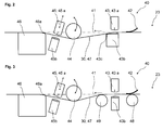
- Fig. 2
- eine erste Ausführungsform einer Vorrichtung zur Verfestigung eines Faserflores von einer Krempelanlage an eine weitere Verarbeitungsstation;
- Fig. 3
- eine zweite Ausführungsform einer Vorrichtung zur Verfestigung eines Faserflores von einer Krempelanlage an eine weitere Verarbeitungsstation;
- Fig. 4
- eine dritte Ausführungsform einer Vorrichtung zur Verfestigung eines Faserflores von einer Krempelanlage an eine weitere Verarbeitungsstation, beispielsweise einen Schrägsiebformer;
- Fig. 5
- eine vierte Ausführungsform einer Vorrichtung zur Verfestigung eines Faserflores von einer Krempelanlage an eine weitere Verarbeitungsstation, beispielsweise einen Schrägsiebformer.
- Fig. 1
- a layout of a fiber processing apparatus with a carding machine and a Schrägsiebformer;
- Fig. 2
- a first embodiment of an apparatus for solidifying a Faserflores of a carding machine to a further processing station;
- Fig. 3
- a second embodiment of an apparatus for solidifying a Faserflores of a carding machine to a further processing station;
- Fig. 4
- a third embodiment of an apparatus for solidifying a Faserflores of a carding machine to another processing station, such as a Schrägsiebformer;
- Fig. 5
- a fourth embodiment of an apparatus for solidifying a Faserflores of a carding machine to another processing station, such as a Schrägsiebformer.
In
In der Krempelanlage 20 werden die Faserflocken an der Einlaufseite 21 der Anlage zugeführt und über nicht näher bezeichnete Elemente wie Einzugswalzen, Vortrommel und Übertragungseinheit bis zum Tambour 22 geleitet, so dass die Faserflocken bis zur Einzelfaser aufgelöst und ausgerichtet werden. Während des Transportvorganges der Faserflocken halten Wender- und Arbeiterwalzen die Fasern auf der Vortrommel bzw. auf dem Tambour 22, so dass sich ein Faserflor 30 bildet, der nach dem Tambour 22 von einer Abnehmerwalze in Richtung Auslaufseite 23 transportiert wird. An die Abnehmerwalzen schließen sich eine oder mehrere Stauchwalzen an, sowie ein Abzugsaggregat in Form eines umlaufenden Transportbandes 24, das gegebenenfalls mit einer oder mehreren Übergabewalzen ausgestattet sein kann. Die in
In der Verfestigungsvorrichtung 40 wird der Faserflor 30 verfestigt und auf ein Transportband 55 eines Schrägsiebformers 50 übergeben. Die Funktionsweise der Verfestigungsvorrichtung 40 wird anhand der
Die Verfestigungsvorrichtung 40 kann als separate und eigenständige Anlagenkomponente zwischen der Krempelanlage 20 und dem Schrägsiebformer 50 angeordnet sein. Dies wird anhand der
Die Übergabe des Faserflors 30 von der Auslaufseite 23 der Krempelanlage 20 zur Verfestigungsvorrichtung 40 und/oder weiter in den Schrägsiebformer 50 kann in freier Übergabe von Band zu Band 47 erfolgen. Alternativ kann eine Saugwalze, ein Übergabeband oder eine Übergabewalze verwendet werden.The transfer of the
Der Schrägsiebformer 50 weist einen Stoffauflauf 51 auf, mit dem eine Schicht von losen Fasern nass auf einem Formierband 53 abgelegt werden kann. Unterhalb des Stoffauflaufes 51 sind eine oder mehrere Saugzonen 52 angeordnet, mit denen das Wasser abgezogen werden kann. Die Fasern liegen damit lose auf dem Formierband 53 auf und werden bis zu einer Umlenkwalze 54, die eine Übergabestelle bildet, transportiert, an der die Schicht von losen Fasern mit der Oberseite, also kopfüber, auf einem unterhalb des Formierbandes 53 angeordneten Transportband 55 ablegbar sind. Da auf diesem Transportband 55 schon der Faserflor 30 von der Krempelanlage 20 aufliegen kann, erfolgt auf dem Transportband 55 eine Übergabe der losen Fasern kopfüber auf dem Faserflor 30.The
In Materialflussrichtung nach dem Schrägsiebformer 50 ist eine weitere Verfestigungsstation 60 angeordnet, die aus mindestens einem Wasserbalken mit zugehöriger Absaugung besteht und mit Hochdruckwasserstrahlen mit 40 - 250 bar den Faserflor mit den lose gelegten Fasern verbindet.In the material flow direction after the
Die Elemente der Verfestigungsvorrichtung 40 orientieren sich alle entlang einer Einfahrlinie 41, die in Materialflussrichtung (Pfeil) die Auslaufseite 23 der Krempelanlage 20 mit dem Transportband 55 des Schrägsiebformers 50 verbindet. In dieser Verfestigungsvorrichtung 40 wird der Faserflor 30 für die Übergabe an den Schrägsiebformer 50 vorverfestigt.The elements of the
In einer ersten Ausführungsform nach der
In dem Ausführungsbeispiel der
Beide Ausführungsformen haben den Vorteil, dass der Faserflor 30 mit einer Vorverfestigung mit der Schicht von losen Fasern (Pulp oder den nassgelegten Fasern des Schrägsiebformers) in Kontakt kommt und zusammen weiter verarbeitet wird, wodurch die Verarbeitungsgeschwindigkeit erhöht werden kann oder sehr leichte Faserflore ohne Qualitätsverlust verarbeitbar sind. Die Fahrweise der Verfestigungsvorrichtung 40 nach
In einer dritten Ausführungsform nach der
Eine in Materialflussrichtung nachfolgend angeordnete einstellbare Umlenkwalze 54 lenkt das Formiersieb 53 um, auf dem die Schicht von lose gelegten Fasern, die aus einer Pulpanlage oder dem hier dargestellten Schrägsiebformer 50 kommen, abgelegt werden. In diesem Ausführungsbeispiel erfolgt die Übergabe der Schicht von losen Fasern kopfüber auf dem Faserflor 30, wobei die Umlenkwalze 54 den Faserflor 30 gleichzeitig aus der Einfahrlinie - in diesem Fall nach unten drückt - und dabei den Faserflor 30 und die losen Fasern kompaktiert. Eine weitere nachfolgend angeordnete zweite Verfestigung 45 ist in diesem Ausführungsbeispiel nicht in Betrieb, kann aber jederzeit dazu geschaltet werden. Nach der zweiten Verfestigung 45 ist eine Auflage 46 angeordnet, die das Transportband 55 abstützt und führt. Dadurch, dass die Walze 54 den Faserflor 30 aus der Einfahrlinie 41 drückt, ergibt sich zumindest an den Auflagepunkten der Auflage 46 und der Absaugung 43b eine Kontaktstelle mit dem Faserflor 30 und den aufgelegten losen Fasern. Um dies möglichst schonend zu gestalten und den Faserflor 30 nicht zu beschädigen, weisen die Auflage 46 und die Absaugung 43b an den Kontaktstellen mit dem Faserflor 30 eine Rundung 46a, 43c bzw. Abschrägung auf. Durch die Umlenkung des Faserflors 30 an der Rundung 43c, durch die Walze 54 und durch die Rundung 46a erfolgt jeweils eine weitere leichte Kompaktierung der Faserverbindung.An
Vorteilhafterweise ist die Walze 54 in die Einfahrlinie 41 herein oder heraus fahrbar gestaltet, also durch beispielsweise ein vertikales Verfahren oder Verschwenken. Da der Schrägsiebformer und die Krempelanlage Teil einer Gesamtanlage sind, die weitere oder alternative Verfahrensschritte zur Verarbeitung von losen Fasern oder von einem Krempelvlies vorsehen, kann durch das Hochschwenken der Umlenkwalze 54 die Gesamtanlage auch ohne den Schrägsiebformer betrieben werden. Beispielsweise kann ein Krempelvlies ohne die Schicht von lose gelegte Fasern aus dem Schrägsiebformer in Verbindung mit einem nachfolgend weiteren zuführbaren Vlies, Stapelfasern, Endlosfasern, Spunbond oder kardiertem Vlies zur Herstellung von mehrschichtigen Vliesen verarbeitet werden.Advantageously, the
In dem Ausführungsbeispiel der
Auch hier weist die nachfolgende Auflage 46 zur Führung und Abstützung des Transportbandes 55 eine Rundung 46a auf, um den Faserflor 30 nicht zu beschädigen. Durch die Verfahrbarkeit von der Walze 54 und der Verfestigung 45 in oder aus der Ausfahrlinie heraus kann einerseits das Einlegen oder Übergeben des Faserflores 30 von der Krempelanlage 20 in den Schrägsiebformer 50 leichter gestaltet werden, und gleichzeitig die Größe der Kompaktierung beeinflusst werden.Again, the
Diese Ausführungsformen haben den Vorteil, dass der Faserflor 30 wahlweise mit oder ohne Vorverfestigung mit den losen Fasern (Pulp oder den nassgelegten Fasern des Schrägsiebformers) in Kontakt kommen kann und bei einer Vorverfestigung die Verarbeitungsgeschwindigkeit erhöht werden kann, oder alternativ sehr leichte Faserflore verarbeitet werden können. Ein weiterer Vorteil dieser Ausführungsformen ist die mögliche Integrierbarkeit der Verfestigungsvorrichtung 40 in den Schrägsiebformer 50, wobei die verfahrbare/verschwenkbare Anordnung der Umlenkwalze 54 einerseits die Gesamtanlage flexibel macht, andererseits damit eine Kompaktierung von Faserflor 30 und losen Fasern möglich und einstellbar ist.These embodiments have the advantage that the
Allen Ausführungsformen ist gemeinsam, dass sowohl die erste und zweite Kompaktierung wie auch die erste und zweite Verfestigung variabel ein- und ausschaltbar sind, je nach Anlagenkonfiguration.All embodiments have in common that both the first and second compaction as well as the first and second solidification are variable on and off, depending on the system configuration.
- 11
- Anlageinvestment
- 1010
- SpeiserSpeiser
- 1111
- Transportbandconveyor belt
- 2020
- Krempelanlageroller card
- 2121
- Einlaufseiteinlet side
- 2222
- Tambourdrummer
- 2323
- Auslaufseiteoutlet side
- 2424
- Transportbandconveyor belt
- 2525
- Transportbandconveyor belt
- 3030
- Faserflorbatt
- 4040
- Verfestigungsvorrichtungsolidifying means
- 4141
- EinfahrlinieEinfahrlinie
- 4242
- Kompaktierungcompacting
- 4343
- Verfestigungconsolidation
- 43a43a
- Düsenbalkennozzle beam
- 43b43b
- Absaugungsuction
- 43c43c
- Rundungcurve
- 4444
- Walzeroller
- 4545
- Verfestigungconsolidation
- 45a45a
- Düsenbalkennozzle beam
- 45b45b
- Absaugungsuction
- 4646
- Auflageedition
- 46a46a
- Rundungcurve
- 4747
- Transportbandconveyor belt
- 4848
- Walzeroller
- 4949
- Walzeroller
- 5050
- SchrägsiebformerSchrägsiebformer
- 5151
- Stoffauflaufheadbox
- 5252
- Saugzonensuction zones
- 5353
- Formierbandforming belt
- 5454
- Umlenkwalzedeflecting
- 5555
- Transportbandconveyor belt
- 5656
- Walzeroller
- 6060
- Verfestigungsstationstrengthening station
Claims (18)
Applications Claiming Priority (1)
| Application Number | Priority Date | Filing Date | Title |
|---|---|---|---|
| DE102015111340.6A DE102015111340A1 (en) | 2015-07-14 | 2015-07-14 | Plant and method for producing a multi-layer nonwoven fabric from at least one unconsolidated batt |
Publications (2)
| Publication Number | Publication Date |
|---|---|
| EP3118361A1 true EP3118361A1 (en) | 2017-01-18 |
| EP3118361B1 EP3118361B1 (en) | 2019-02-27 |
Family
ID=56026627
Family Applications (1)
| Application Number | Title | Priority Date | Filing Date |
|---|---|---|---|
| EP16001135.9A Revoked EP3118361B1 (en) | 2015-07-14 | 2016-05-19 | Installation and method for making a multi-layer nonwoven fabric from at least one loose fibre web |
Country Status (3)
| Country | Link |
|---|---|
| EP (1) | EP3118361B1 (en) |
| CN (1) | CN106350944B (en) |
| DE (1) | DE102015111340A1 (en) |
Cited By (7)
| Publication number | Priority date | Publication date | Assignee | Title |
|---|---|---|---|---|
| CN107385987A (en) * | 2017-09-15 | 2017-11-24 | 宁波华辰机械有限公司 | A kind of inclined wire paper making equipment |
| EP3495544A1 (en) * | 2017-12-08 | 2019-06-12 | Trützschler GmbH & Co. KG | Device for hydro-needling nonwoven fabrics, tissues or knitted fabrics |
| CN112725949A (en) * | 2020-12-11 | 2021-04-30 | 孙建平 | A conveying equipment for refined cotton |
| WO2021139932A1 (en) * | 2020-01-10 | 2021-07-15 | TRüTZSCHLER GMBH & CO. KG | System and method for producing a single- or multi-layer nonwoven |
| CN115074917A (en) * | 2022-07-15 | 2022-09-20 | 厦门当盛新材料有限公司 | Novel bacterium-blocking breathable fabric and preparation method thereof |
| EP4067549B1 (en) | 2021-03-29 | 2023-01-25 | Andritz Küsters GmbH | System and method for consolidating layers comprising fibres to a nonwoven web |
| WO2023104365A1 (en) * | 2021-12-06 | 2023-06-15 | Trützschler Group SE | System and method for producing a single-layer or multi-layer nonwoven |
Families Citing this family (2)
| Publication number | Priority date | Publication date | Assignee | Title |
|---|---|---|---|---|
| CN107190420A (en) * | 2017-07-26 | 2017-09-22 | 唐新雄 | Super dry and comfortable hot-wind nonwoven cloth fabric process units |
| CN110592803B (en) * | 2019-10-10 | 2020-09-04 | 上海盈兹无纺布有限公司 | Hot-air non-woven fabric hot-press forming equipment and method for preparing non-woven fabric |
Citations (5)
| Publication number | Priority date | Publication date | Assignee | Title |
|---|---|---|---|---|
| WO2001063032A1 (en) * | 2000-02-24 | 2001-08-30 | Fleissner Gmbh & Co. Maschinenfabrik | Method and device for producing composite nonwovens by means of hydrodynamic needling |
| WO2008074665A1 (en) * | 2006-12-16 | 2008-06-26 | Oerlikon Textile Gmbh & Co. Kg | Method of, and apparatus for, producing a nonwoven |
| EP1929080B1 (en) | 2005-09-26 | 2009-04-29 | Kimberly-Clark Worldwide, Inc. | Manufacturing process for combining a layer of pulp fibers with another substrate |
| EP2096207A1 (en) * | 2008-02-28 | 2009-09-02 | Voith Patent GmbH | Inclined screen former of a machine for producing a sheet of fibrous material from at least one fibrous suspension |
| WO2015049018A1 (en) * | 2013-10-01 | 2015-04-09 | TRüTZSCHLER GMBH & CO. KG | Precompressor for smoothing and/or compacting a carded sliver in a winding machine, winding machine and method of operating a winding machine |
Family Cites Families (8)
| Publication number | Priority date | Publication date | Assignee | Title |
|---|---|---|---|---|
| FR2849869B1 (en) * | 2003-01-14 | 2005-09-09 | Ahlstrom Brignoud | METHOD FOR MANUFACTURING A COMPOSITE NON-WOVEN FABRIC AND INSTALLATION FOR CARRYING OUT SAID METHOD |
| ATE521744T1 (en) * | 2007-03-29 | 2011-09-15 | Truetzschler Nonwovens Gmbh | DEVICE FOR PROCESSING FLOATS |
| EP3321405A1 (en) * | 2008-09-11 | 2018-05-16 | Albany International Corp. | Permeable belt for the manufacture of tissue, towel and nonwovens |
| CN102560903B (en) * | 2011-12-30 | 2015-05-13 | 山东俊富非织造材料有限公司 | Multi-layer composite basalt non-woven material and preparation method thereof |
| CN103006391B (en) * | 2012-12-19 | 2014-05-07 | 博爱(中国)膨化芯材有限公司 | Composite dustless paper and production process and application thereof |
| CN103074776B (en) * | 2013-01-29 | 2015-08-19 | 杭州诺邦无纺股份有限公司 | Microcapsules fill nonwoven fabric and preparation method |
| DE102013101431B4 (en) * | 2013-02-13 | 2016-06-23 | TRüTZSCHLER GMBH & CO. KG | Apparatus and method for the hydrodynamic consolidation of nonwovens, fabrics and knitted fabrics |
| CN103590193B (en) * | 2013-11-11 | 2015-07-29 | 杭州创蓝无纺布有限公司 | Wet method spunlace non-woven cloth process units and technique thereof |
-
2015
- 2015-07-14 DE DE102015111340.6A patent/DE102015111340A1/en active Pending
-
2016
- 2016-05-19 EP EP16001135.9A patent/EP3118361B1/en not_active Revoked
- 2016-06-06 CN CN201610391051.0A patent/CN106350944B/en active Active
Patent Citations (5)
| Publication number | Priority date | Publication date | Assignee | Title |
|---|---|---|---|---|
| WO2001063032A1 (en) * | 2000-02-24 | 2001-08-30 | Fleissner Gmbh & Co. Maschinenfabrik | Method and device for producing composite nonwovens by means of hydrodynamic needling |
| EP1929080B1 (en) | 2005-09-26 | 2009-04-29 | Kimberly-Clark Worldwide, Inc. | Manufacturing process for combining a layer of pulp fibers with another substrate |
| WO2008074665A1 (en) * | 2006-12-16 | 2008-06-26 | Oerlikon Textile Gmbh & Co. Kg | Method of, and apparatus for, producing a nonwoven |
| EP2096207A1 (en) * | 2008-02-28 | 2009-09-02 | Voith Patent GmbH | Inclined screen former of a machine for producing a sheet of fibrous material from at least one fibrous suspension |
| WO2015049018A1 (en) * | 2013-10-01 | 2015-04-09 | TRüTZSCHLER GMBH & CO. KG | Precompressor for smoothing and/or compacting a carded sliver in a winding machine, winding machine and method of operating a winding machine |
Cited By (12)
| Publication number | Priority date | Publication date | Assignee | Title |
|---|---|---|---|---|
| CN107385987A (en) * | 2017-09-15 | 2017-11-24 | 宁波华辰机械有限公司 | A kind of inclined wire paper making equipment |
| CN107385987B (en) * | 2017-09-15 | 2023-08-04 | 宁波华辰机械有限公司 | Inclined wire papermaking equipment |
| EP3495544A1 (en) * | 2017-12-08 | 2019-06-12 | Trützschler GmbH & Co. KG | Device for hydro-needling nonwoven fabrics, tissues or knitted fabrics |
| WO2021139932A1 (en) * | 2020-01-10 | 2021-07-15 | TRüTZSCHLER GMBH & CO. KG | System and method for producing a single- or multi-layer nonwoven |
| WO2021139933A3 (en) * | 2020-01-10 | 2021-08-26 | TRüTZSCHLER GMBH & CO. KG | System and method for producing a single- or multi-layer nonwoven |
| CN115023516A (en) * | 2020-01-10 | 2022-09-06 | 特吕茨施勒集团欧洲公司 | Apparatus and method for producing single-layer or multi-layer nonwoven fabrics |
| CN112725949A (en) * | 2020-12-11 | 2021-04-30 | 孙建平 | A conveying equipment for refined cotton |
| CN112725949B (en) * | 2020-12-11 | 2023-06-23 | 宁夏德圣亚科技有限公司 | Conveying equipment for refined cotton |
| EP4067549B1 (en) | 2021-03-29 | 2023-01-25 | Andritz Küsters GmbH | System and method for consolidating layers comprising fibres to a nonwoven web |
| WO2023104365A1 (en) * | 2021-12-06 | 2023-06-15 | Trützschler Group SE | System and method for producing a single-layer or multi-layer nonwoven |
| CN115074917A (en) * | 2022-07-15 | 2022-09-20 | 厦门当盛新材料有限公司 | Novel bacterium-blocking breathable fabric and preparation method thereof |
| CN115074917B (en) * | 2022-07-15 | 2023-09-19 | 厦门当盛新材料有限公司 | Novel bacteria-resistant breathable fabric and preparation method thereof |
Also Published As
| Publication number | Publication date |
|---|---|
| DE102015111340A1 (en) | 2017-01-19 |
| CN106350944B (en) | 2018-11-09 |
| CN106350944A (en) | 2017-01-25 |
| EP3118361B1 (en) | 2019-02-27 |
Similar Documents
| Publication | Publication Date | Title |
|---|---|---|
| EP3118361B1 (en) | Installation and method for making a multi-layer nonwoven fabric from at least one loose fibre web | |
| EP3283679B1 (en) | Plant and method for connecting a web of fibrous material to a nonwoven or consolidating it therewith | |
| DE3224118C1 (en) | Card for making nonwovens from fibrous materials | |
| DE102013113493A1 (en) | stacker | |
| EP2420604B1 (en) | Non-woven fabric laying machine and method for laying a non-woven fabric | |
| EP3250750A1 (en) | Method and device for producing wet-laid non-woven fabrics | |
| EP3495543B1 (en) | System and method for creating a spunbonded fabric | |
| EP3110997B1 (en) | Carding apparatus and carding method | |
| WO2021228514A1 (en) | System and method for producing a single- or multi-layer nonwoven | |
| EP3061855B1 (en) | Roller card and method for fixing at least one fibre web | |
| AT501434B1 (en) | VLIESZUFÜHRVORRICHTUNG | |
| DE102016217400A1 (en) | Method and device for producing a wet laid nonwoven fabric | |
| EP4067548B1 (en) | System for consolidating layers comprising fibres to a nonwoven web | |
| DE19929105A1 (en) | Process and device for the production of structured nonwovens by means of hydrodynamic needling | |
| WO2019025108A1 (en) | Carding machine | |
| DE102016217401A1 (en) | Method and device for producing a wet laid nonwoven fabric | |
| EP4087966A2 (en) | System and method for producing a single- or multi-layer nonwoven | |
| EP2539498B1 (en) | Device for solidifying a material web | |
| EP2716801B1 (en) | Stacker and method for operating a stacker | |
| EP4168616B1 (en) | Method for the continuous production of nonwoven fabric, and associated nonwoven fabric production apparatus and nonwoven board | |
| WO2023104365A1 (en) | System and method for producing a single-layer or multi-layer nonwoven | |
| DE60304367T2 (en) | METHOD AND DEVICE FOR STABILIZING RIMS OF A NONWOVEN MATERIAL | |
| EP4086388A1 (en) | Apparatus and method for producing a fluid jet needled fibrous web from at least one fibrous suspension | |
| EP3088603B1 (en) | Method and device for the preparation of wet placed nonwoven fabrics | |
| EP4299807A1 (en) | Method for forming a nonwoven from several layers of fibre webs by means of a cross-lapper, cross-lapper and use thereof |
Legal Events
| Date | Code | Title | Description |
|---|---|---|---|
| PUAI | Public reference made under article 153(3) epc to a published international application that has entered the european phase |
Free format text: ORIGINAL CODE: 0009012 |
|
| STAA | Information on the status of an ep patent application or granted ep patent |
Free format text: STATUS: THE APPLICATION HAS BEEN PUBLISHED |
|
| AK | Designated contracting states |
Kind code of ref document: A1 Designated state(s): AL AT BE BG CH CY CZ DE DK EE ES FI FR GB GR HR HU IE IS IT LI LT LU LV MC MK MT NL NO PL PT RO RS SE SI SK SM TR |
|
| AX | Request for extension of the european patent |
Extension state: BA ME |
|
| STAA | Information on the status of an ep patent application or granted ep patent |
Free format text: STATUS: REQUEST FOR EXAMINATION WAS MADE |
|
| 17P | Request for examination filed |
Effective date: 20170718 |
|
| RBV | Designated contracting states (corrected) |
Designated state(s): AL AT BE BG CH CY CZ DE DK EE ES FI FR GB GR HR HU IE IS IT LI LT LU LV MC MK MT NL NO PL PT RO RS SE SI SK SM TR |
|
| STAA | Information on the status of an ep patent application or granted ep patent |
Free format text: STATUS: EXAMINATION IS IN PROGRESS |
|
| 17Q | First examination report despatched |
Effective date: 20180221 |
|
| GRAP | Despatch of communication of intention to grant a patent |
Free format text: ORIGINAL CODE: EPIDOSNIGR1 |
|
| STAA | Information on the status of an ep patent application or granted ep patent |
Free format text: STATUS: GRANT OF PATENT IS INTENDED |
|
| INTG | Intention to grant announced |
Effective date: 20180917 |
|
| GRAS | Grant fee paid |
Free format text: ORIGINAL CODE: EPIDOSNIGR3 |
|
| GRAA | (expected) grant |
Free format text: ORIGINAL CODE: 0009210 |
|
| STAA | Information on the status of an ep patent application or granted ep patent |
Free format text: STATUS: THE PATENT HAS BEEN GRANTED |
|
| AK | Designated contracting states |
Kind code of ref document: B1 Designated state(s): AL AT BE BG CH CY CZ DE DK EE ES FI FR GB GR HR HU IE IS IT LI LT LU LV MC MK MT NL NO PL PT RO RS SE SI SK SM TR |
|
| REG | Reference to a national code |
Ref country code: GB Ref legal event code: FG4D Free format text: NOT ENGLISH |
|
| REG | Reference to a national code |
Ref country code: CH Ref legal event code: EP |
|
| REG | Reference to a national code |
Ref country code: AT Ref legal event code: REF Ref document number: 1101483 Country of ref document: AT Kind code of ref document: T Effective date: 20190315 |
|
| REG | Reference to a national code |
Ref country code: IE Ref legal event code: FG4D Free format text: LANGUAGE OF EP DOCUMENT: GERMAN |
|
| REG | Reference to a national code |
Ref country code: DE Ref legal event code: R096 Ref document number: 502016003485 Country of ref document: DE |
|
| REG | Reference to a national code |
Ref country code: NL Ref legal event code: MP Effective date: 20190227 |
|
| REG | Reference to a national code |
Ref country code: LT Ref legal event code: MG4D |
|
| PG25 | Lapsed in a contracting state [announced via postgrant information from national office to epo] |
Ref country code: SE Free format text: LAPSE BECAUSE OF FAILURE TO SUBMIT A TRANSLATION OF THE DESCRIPTION OR TO PAY THE FEE WITHIN THE PRESCRIBED TIME-LIMIT Effective date: 20190227 Ref country code: NL Free format text: LAPSE BECAUSE OF FAILURE TO SUBMIT A TRANSLATION OF THE DESCRIPTION OR TO PAY THE FEE WITHIN THE PRESCRIBED TIME-LIMIT Effective date: 20190227 Ref country code: PT Free format text: LAPSE BECAUSE OF FAILURE TO SUBMIT A TRANSLATION OF THE DESCRIPTION OR TO PAY THE FEE WITHIN THE PRESCRIBED TIME-LIMIT Effective date: 20190627 Ref country code: FI Free format text: LAPSE BECAUSE OF FAILURE TO SUBMIT A TRANSLATION OF THE DESCRIPTION OR TO PAY THE FEE WITHIN THE PRESCRIBED TIME-LIMIT Effective date: 20190227 Ref country code: NO Free format text: LAPSE BECAUSE OF FAILURE TO SUBMIT A TRANSLATION OF THE DESCRIPTION OR TO PAY THE FEE WITHIN THE PRESCRIBED TIME-LIMIT Effective date: 20190527 Ref country code: LT Free format text: LAPSE BECAUSE OF FAILURE TO SUBMIT A TRANSLATION OF THE DESCRIPTION OR TO PAY THE FEE WITHIN THE PRESCRIBED TIME-LIMIT Effective date: 20190227 |
|
| PG25 | Lapsed in a contracting state [announced via postgrant information from national office to epo] |
Ref country code: IS Free format text: LAPSE BECAUSE OF FAILURE TO SUBMIT A TRANSLATION OF THE DESCRIPTION OR TO PAY THE FEE WITHIN THE PRESCRIBED TIME-LIMIT Effective date: 20190627 Ref country code: GR Free format text: LAPSE BECAUSE OF FAILURE TO SUBMIT A TRANSLATION OF THE DESCRIPTION OR TO PAY THE FEE WITHIN THE PRESCRIBED TIME-LIMIT Effective date: 20190528 Ref country code: HR Free format text: LAPSE BECAUSE OF FAILURE TO SUBMIT A TRANSLATION OF THE DESCRIPTION OR TO PAY THE FEE WITHIN THE PRESCRIBED TIME-LIMIT Effective date: 20190227 Ref country code: LV Free format text: LAPSE BECAUSE OF FAILURE TO SUBMIT A TRANSLATION OF THE DESCRIPTION OR TO PAY THE FEE WITHIN THE PRESCRIBED TIME-LIMIT Effective date: 20190227 Ref country code: BG Free format text: LAPSE BECAUSE OF FAILURE TO SUBMIT A TRANSLATION OF THE DESCRIPTION OR TO PAY THE FEE WITHIN THE PRESCRIBED TIME-LIMIT Effective date: 20190527 Ref country code: RS Free format text: LAPSE BECAUSE OF FAILURE TO SUBMIT A TRANSLATION OF THE DESCRIPTION OR TO PAY THE FEE WITHIN THE PRESCRIBED TIME-LIMIT Effective date: 20190227 |
|
| PG25 | Lapsed in a contracting state [announced via postgrant information from national office to epo] |
Ref country code: CZ Free format text: LAPSE BECAUSE OF FAILURE TO SUBMIT A TRANSLATION OF THE DESCRIPTION OR TO PAY THE FEE WITHIN THE PRESCRIBED TIME-LIMIT Effective date: 20190227 Ref country code: ES Free format text: LAPSE BECAUSE OF FAILURE TO SUBMIT A TRANSLATION OF THE DESCRIPTION OR TO PAY THE FEE WITHIN THE PRESCRIBED TIME-LIMIT Effective date: 20190227 Ref country code: RO Free format text: LAPSE BECAUSE OF FAILURE TO SUBMIT A TRANSLATION OF THE DESCRIPTION OR TO PAY THE FEE WITHIN THE PRESCRIBED TIME-LIMIT Effective date: 20190227 Ref country code: IT Free format text: LAPSE BECAUSE OF FAILURE TO SUBMIT A TRANSLATION OF THE DESCRIPTION OR TO PAY THE FEE WITHIN THE PRESCRIBED TIME-LIMIT Effective date: 20190227 Ref country code: EE Free format text: LAPSE BECAUSE OF FAILURE TO SUBMIT A TRANSLATION OF THE DESCRIPTION OR TO PAY THE FEE WITHIN THE PRESCRIBED TIME-LIMIT Effective date: 20190227 Ref country code: DK Free format text: LAPSE BECAUSE OF FAILURE TO SUBMIT A TRANSLATION OF THE DESCRIPTION OR TO PAY THE FEE WITHIN THE PRESCRIBED TIME-LIMIT Effective date: 20190227 Ref country code: SK Free format text: LAPSE BECAUSE OF FAILURE TO SUBMIT A TRANSLATION OF THE DESCRIPTION OR TO PAY THE FEE WITHIN THE PRESCRIBED TIME-LIMIT Effective date: 20190227 Ref country code: AL Free format text: LAPSE BECAUSE OF FAILURE TO SUBMIT A TRANSLATION OF THE DESCRIPTION OR TO PAY THE FEE WITHIN THE PRESCRIBED TIME-LIMIT Effective date: 20190227 |
|
| REG | Reference to a national code |
Ref country code: DE Ref legal event code: R026 Ref document number: 502016003485 Country of ref document: DE |
|
| PG25 | Lapsed in a contracting state [announced via postgrant information from national office to epo] |
Ref country code: PL Free format text: LAPSE BECAUSE OF FAILURE TO SUBMIT A TRANSLATION OF THE DESCRIPTION OR TO PAY THE FEE WITHIN THE PRESCRIBED TIME-LIMIT Effective date: 20190227 Ref country code: SM Free format text: LAPSE BECAUSE OF FAILURE TO SUBMIT A TRANSLATION OF THE DESCRIPTION OR TO PAY THE FEE WITHIN THE PRESCRIBED TIME-LIMIT Effective date: 20190227 |
|
| RAP2 | Party data changed (patent owner data changed or rights of a patent transferred) |
Owner name: TRUETZSCHLER GMBH & CO. KG Owner name: VOITH PATENT GMBH |
|
| PLBI | Opposition filed |
Free format text: ORIGINAL CODE: 0009260 |
|
| PLAX | Notice of opposition and request to file observation + time limit sent |
Free format text: ORIGINAL CODE: EPIDOSNOBS2 |
|
| REG | Reference to a national code |
Ref country code: CH Ref legal event code: PL |
|
| 26 | Opposition filed |
Opponent name: ANDRITZ KUESTERS GMBH Effective date: 20191121 |
|
| PG25 | Lapsed in a contracting state [announced via postgrant information from national office to epo] |
Ref country code: MC Free format text: LAPSE BECAUSE OF FAILURE TO SUBMIT A TRANSLATION OF THE DESCRIPTION OR TO PAY THE FEE WITHIN THE PRESCRIBED TIME-LIMIT Effective date: 20190227 Ref country code: LI Free format text: LAPSE BECAUSE OF NON-PAYMENT OF DUE FEES Effective date: 20190531 Ref country code: CH Free format text: LAPSE BECAUSE OF NON-PAYMENT OF DUE FEES Effective date: 20190531 |
|
| REG | Reference to a national code |
Ref country code: BE Ref legal event code: MM Effective date: 20190531 |
|
| PLBB | Reply of patent proprietor to notice(s) of opposition received |
Free format text: ORIGINAL CODE: EPIDOSNOBS3 |
|
| PG25 | Lapsed in a contracting state [announced via postgrant information from national office to epo] |
Ref country code: SI Free format text: LAPSE BECAUSE OF FAILURE TO SUBMIT A TRANSLATION OF THE DESCRIPTION OR TO PAY THE FEE WITHIN THE PRESCRIBED TIME-LIMIT Effective date: 20190227 Ref country code: LU Free format text: LAPSE BECAUSE OF NON-PAYMENT OF DUE FEES Effective date: 20190519 |
|
| PG25 | Lapsed in a contracting state [announced via postgrant information from national office to epo] |
Ref country code: TR Free format text: LAPSE BECAUSE OF FAILURE TO SUBMIT A TRANSLATION OF THE DESCRIPTION OR TO PAY THE FEE WITHIN THE PRESCRIBED TIME-LIMIT Effective date: 20190227 |
|
| PG25 | Lapsed in a contracting state [announced via postgrant information from national office to epo] |
Ref country code: IE Free format text: LAPSE BECAUSE OF NON-PAYMENT OF DUE FEES Effective date: 20190519 |
|
| PG25 | Lapsed in a contracting state [announced via postgrant information from national office to epo] |
Ref country code: BE Free format text: LAPSE BECAUSE OF NON-PAYMENT OF DUE FEES Effective date: 20190531 |
|
| PLAY | Examination report in opposition despatched + time limit |
Free format text: ORIGINAL CODE: EPIDOSNORE2 |
|
| PLAL | Information related to reply to examination report in opposition modified |
Free format text: ORIGINAL CODE: EPIDOSCORE3 |
|
| PLBC | Reply to examination report in opposition received |
Free format text: ORIGINAL CODE: EPIDOSNORE3 |
|
| GBPC | Gb: european patent ceased through non-payment of renewal fee |
Effective date: 20200519 |
|
| APBM | Appeal reference recorded |
Free format text: ORIGINAL CODE: EPIDOSNREFNO |
|
| APBP | Date of receipt of notice of appeal recorded |
Free format text: ORIGINAL CODE: EPIDOSNNOA2O |
|
| APAH | Appeal reference modified |
Free format text: ORIGINAL CODE: EPIDOSCREFNO |
|
| PG25 | Lapsed in a contracting state [announced via postgrant information from national office to epo] |
Ref country code: GB Free format text: LAPSE BECAUSE OF NON-PAYMENT OF DUE FEES Effective date: 20200519 |
|
| PG25 | Lapsed in a contracting state [announced via postgrant information from national office to epo] |
Ref country code: CY Free format text: LAPSE BECAUSE OF FAILURE TO SUBMIT A TRANSLATION OF THE DESCRIPTION OR TO PAY THE FEE WITHIN THE PRESCRIBED TIME-LIMIT Effective date: 20190227 |
|
| APBQ | Date of receipt of statement of grounds of appeal recorded |
Free format text: ORIGINAL CODE: EPIDOSNNOA3O |
|
| PG25 | Lapsed in a contracting state [announced via postgrant information from national office to epo] |
Ref country code: HU Free format text: LAPSE BECAUSE OF FAILURE TO SUBMIT A TRANSLATION OF THE DESCRIPTION OR TO PAY THE FEE WITHIN THE PRESCRIBED TIME-LIMIT; INVALID AB INITIO Effective date: 20160519 Ref country code: MT Free format text: LAPSE BECAUSE OF FAILURE TO SUBMIT A TRANSLATION OF THE DESCRIPTION OR TO PAY THE FEE WITHIN THE PRESCRIBED TIME-LIMIT Effective date: 20190227 |
|
| PG25 | Lapsed in a contracting state [announced via postgrant information from national office to epo] |
Ref country code: MK Free format text: LAPSE BECAUSE OF FAILURE TO SUBMIT A TRANSLATION OF THE DESCRIPTION OR TO PAY THE FEE WITHIN THE PRESCRIBED TIME-LIMIT Effective date: 20190227 |
|
| REG | Reference to a national code |
Ref country code: AT Ref legal event code: PC Ref document number: 1101483 Country of ref document: AT Kind code of ref document: T Owner name: VOITH PATENT GMBH, DE Effective date: 20220516 Ref country code: AT Ref legal event code: PC Ref document number: 1101483 Country of ref document: AT Kind code of ref document: T Owner name: TRUETZSCHLER GROUP SE, DE Effective date: 20220516 |
|
| REG | Reference to a national code |
Ref country code: DE Ref legal event code: R081 Ref document number: 502016003485 Country of ref document: DE Owner name: VOITH PATENT GMBH, DE Free format text: FORMER OWNERS: TRUETZSCHLER GMBH & CO. KG, 41199 MOENCHENGLADBACH, DE; VOITH PATENT GMBH, 89522 HEIDENHEIM, DE Ref country code: DE Ref legal event code: R081 Ref document number: 502016003485 Country of ref document: DE Owner name: TRUETZSCHLER GROUP SE, DE Free format text: FORMER OWNERS: TRUETZSCHLER GMBH & CO. KG, 41199 MOENCHENGLADBACH, DE; VOITH PATENT GMBH, 89522 HEIDENHEIM, DE |
|
| PLAB | Opposition data, opponent's data or that of the opponent's representative modified |
Free format text: ORIGINAL CODE: 0009299OPPO |
|
| R26 | Opposition filed (corrected) |
Opponent name: ANDRITZ KUESTERS GMBH Effective date: 20191121 |
|
| PGFP | Annual fee paid to national office [announced via postgrant information from national office to epo] |
Ref country code: FR Payment date: 20230526 Year of fee payment: 8 Ref country code: DE Payment date: 20230519 Year of fee payment: 8 |
|
| P01 | Opt-out of the competence of the unified patent court (upc) registered |
Effective date: 20230622 |
|
| PGFP | Annual fee paid to national office [announced via postgrant information from national office to epo] |
Ref country code: AT Payment date: 20230522 Year of fee payment: 8 |
|
| RAP2 | Party data changed (patent owner data changed or rights of a patent transferred) |
Owner name: VOITH PATENT GMBH Owner name: TRUETZSCHLER GROUP SE |
|
| REG | Reference to a national code |
Ref country code: DE Ref legal event code: R103 Ref document number: 502016003485 Country of ref document: DE Ref country code: DE Ref legal event code: R064 Ref document number: 502016003485 Country of ref document: DE |
|
| APBU | Appeal procedure closed |
Free format text: ORIGINAL CODE: EPIDOSNNOA9O |
|
| RDAF | Communication despatched that patent is revoked |
Free format text: ORIGINAL CODE: EPIDOSNREV1 |
|
| RDAG | Patent revoked |
Free format text: ORIGINAL CODE: 0009271 |
|
| STAA | Information on the status of an ep patent application or granted ep patent |
Free format text: STATUS: PATENT REVOKED |
|
| REG | Reference to a national code |
Ref country code: CH Ref legal event code: PL |
|
| 27W | Patent revoked |
Effective date: 20231026 |
|
| REG | Reference to a national code |
Ref country code: AT Ref legal event code: MA03 Ref document number: 1101483 Country of ref document: AT Kind code of ref document: T Effective date: 20231026 |