EP3118153B2 - Verfahren zur hinderniserfassung bei einem flurförderzeug - Google Patents
Verfahren zur hinderniserfassung bei einem flurförderzeug Download PDFInfo
- Publication number
- EP3118153B2 EP3118153B2 EP16177593.7A EP16177593A EP3118153B2 EP 3118153 B2 EP3118153 B2 EP 3118153B2 EP 16177593 A EP16177593 A EP 16177593A EP 3118153 B2 EP3118153 B2 EP 3118153B2
- Authority
- EP
- European Patent Office
- Prior art keywords
- map
- industrial truck
- sensor
- objects
- obstacles
- Prior art date
- Legal status (The legal status is an assumption and is not a legal conclusion. Google has not performed a legal analysis and makes no representation as to the accuracy of the status listed.)
- Active
Links
Images


Classifications
-
- B—PERFORMING OPERATIONS; TRANSPORTING
- B66—HOISTING; LIFTING; HAULING
- B66F—HOISTING, LIFTING, HAULING OR PUSHING, NOT OTHERWISE PROVIDED FOR, e.g. DEVICES WHICH APPLY A LIFTING OR PUSHING FORCE DIRECTLY TO THE SURFACE OF A LOAD
- B66F9/00—Devices for lifting or lowering bulky or heavy goods for loading or unloading purposes
- B66F9/06—Devices for lifting or lowering bulky or heavy goods for loading or unloading purposes movable, with their loads, on wheels or the like, e.g. fork-lift trucks
- B66F9/063—Automatically guided
-
- B—PERFORMING OPERATIONS; TRANSPORTING
- B66—HOISTING; LIFTING; HAULING
- B66F—HOISTING, LIFTING, HAULING OR PUSHING, NOT OTHERWISE PROVIDED FOR, e.g. DEVICES WHICH APPLY A LIFTING OR PUSHING FORCE DIRECTLY TO THE SURFACE OF A LOAD
- B66F17/00—Safety devices, e.g. for limiting or indicating lifting force
- B66F17/003—Safety devices, e.g. for limiting or indicating lifting force for fork-lift trucks
-
- B—PERFORMING OPERATIONS; TRANSPORTING
- B66—HOISTING; LIFTING; HAULING
- B66F—HOISTING, LIFTING, HAULING OR PUSHING, NOT OTHERWISE PROVIDED FOR, e.g. DEVICES WHICH APPLY A LIFTING OR PUSHING FORCE DIRECTLY TO THE SURFACE OF A LOAD
- B66F9/00—Devices for lifting or lowering bulky or heavy goods for loading or unloading purposes
- B66F9/06—Devices for lifting or lowering bulky or heavy goods for loading or unloading purposes movable, with their loads, on wheels or the like, e.g. fork-lift trucks
- B66F9/075—Constructional features or details
- B66F9/0755—Position control; Position detectors
-
- G—PHYSICS
- G05—CONTROLLING; REGULATING
- G05D—SYSTEMS FOR CONTROLLING OR REGULATING NON-ELECTRIC VARIABLES
- G05D1/00—Control of position, course, altitude or attitude of land, water, air or space vehicles, e.g. using automatic pilots
- G05D1/20—Control system inputs
- G05D1/24—Arrangements for determining position or orientation
- G05D1/242—Means based on the reflection of waves generated by the vehicle
-
- G—PHYSICS
- G05—CONTROLLING; REGULATING
- G05D—SYSTEMS FOR CONTROLLING OR REGULATING NON-ELECTRIC VARIABLES
- G05D1/00—Control of position, course, altitude or attitude of land, water, air or space vehicles, e.g. using automatic pilots
- G05D1/20—Control system inputs
- G05D1/24—Arrangements for determining position or orientation
- G05D1/246—Arrangements for determining position or orientation using environment maps, e.g. simultaneous localisation and mapping [SLAM]
- G05D1/2464—Arrangements for determining position or orientation using environment maps, e.g. simultaneous localisation and mapping [SLAM] using an occupancy grid
-
- G—PHYSICS
- G05—CONTROLLING; REGULATING
- G05D—SYSTEMS FOR CONTROLLING OR REGULATING NON-ELECTRIC VARIABLES
- G05D1/00—Control of position, course, altitude or attitude of land, water, air or space vehicles, e.g. using automatic pilots
- G05D1/60—Intended control result
- G05D1/617—Safety or protection, e.g. defining protection zones around obstacles or avoiding hazards
- G05D1/622—Obstacle avoidance
- G05D1/633—Dynamic obstacles
-
- G—PHYSICS
- G05—CONTROLLING; REGULATING
- G05D—SYSTEMS FOR CONTROLLING OR REGULATING NON-ELECTRIC VARIABLES
- G05D2105/00—Specific applications of the controlled vehicles
- G05D2105/20—Specific applications of the controlled vehicles for transportation
- G05D2105/28—Specific applications of the controlled vehicles for transportation of freight
-
- G—PHYSICS
- G05—CONTROLLING; REGULATING
- G05D—SYSTEMS FOR CONTROLLING OR REGULATING NON-ELECTRIC VARIABLES
- G05D2107/00—Specific environments of the controlled vehicles
- G05D2107/70—Industrial sites, e.g. warehouses or factories
-
- G—PHYSICS
- G05—CONTROLLING; REGULATING
- G05D—SYSTEMS FOR CONTROLLING OR REGULATING NON-ELECTRIC VARIABLES
- G05D2109/00—Types of controlled vehicles
- G05D2109/10—Land vehicles
-
- G—PHYSICS
- G05—CONTROLLING; REGULATING
- G05D—SYSTEMS FOR CONTROLLING OR REGULATING NON-ELECTRIC VARIABLES
- G05D2111/00—Details of signals used for control of position, course, altitude or attitude of land, water, air or space vehicles
- G05D2111/10—Optical signals
- G05D2111/17—Coherent light, e.g. laser signals
Definitions
- the invention relates to a method for detecting obstacles in an industrial truck.
- the invention relates to a method for detecting obstacles in the environment of an industrial truck, especially an industrial truck intended for order picking, wherein the industrial truck has a sensor for monitoring the environment, which is connected to a control device and detects a monitoring area by evaluating the data from the sensor.
- a method for detecting obstacles is known from US 2015 0120 125A .
- One of the many possible uses for industrial trucks is assembling goods for delivery to a customer, i.e. order picking.
- special industrial trucks are used to drive through the storage area, for example through rows of shelves.
- Such order picking industrial trucks can be designed so that a person rides along during order picking, but also walks alongside the industrial truck when assembling the goods and driving along a shelf in order to take goods from the shelf and place them on a pallet or in a transport container on the industrial truck.
- Remote controls are known for making it easier to operate the order picking truck. Such remote controls allow the person carrying out the order picking, the picker or operator, to leave the order picking truck and control its movements using the remote control. A known variant of this is that the picker requests that the vehicle move forwards by pressing a button, with the order picking truck moving as long as the button is pressed.
- Control systems for automatically guiding the order picking truck are known, which react to obstacles in a racking aisle by causing the truck to move out of the way.
- Optical sensors are often used for these automatic movements, such as a laser scanner, which can detect obstacles or objects in the racking aisle.
- the disadvantage of this state of the art is that the evasive action takes place regardless of whether and how quickly an object is moving as an obstacle.
- the present invention is therefore based on the object of providing a method for detecting obstacles in an industrial truck, in particular in an industrial truck for order picking, which avoids the aforementioned disadvantages and with which unnecessary evasive movements in front of obstacles in automatic operation are avoided.
- the object is achieved according to the invention in that in a method for detecting obstacles in the surroundings of an industrial truck, in particular an industrial truck intended for order picking, wherein the industrial truck has a sensor for monitoring the surroundings, which is connected to a control device, and detects a monitoring area by evaluating the data from the sensor, objects detected in the surroundings of the industrial truck are entered into a map in the data and the monitoring area is continuously re-detected, wherein for objects at the same absolute position in the map a weighting is increased and for objects missing at the same position the weighting of a registered object is reduced up to and including deletion of the object.
- the sensor which can be any type of sensor suitable for detecting objects in the environment, preferably an optical sensor, records pixels or data and recognizes them as obstacles or objects using known methods of evaluation, in particular image processing. These are entered into a map.
- the data is recorded by the sensor in a continuously repeated manner, for example with a laser scanner with each rotation of the laser beam. This results in a sequence of data sets, whereby an object that is again in the same place is given a higher weighting in the map, and an object that is no longer present in this place is given a lower weighting. This can be done by is reduced. This can be done by increasing the weighting in a certain number of steps from an initial entry value up to a maximum value.
- a fast-moving person is entered in the map at one point as the object with the smallest value in a first step, and since he or she is no longer at this point in the next data set, this object is immediately removed again in a second step and weighted down by the same value.
- This makes it possible to distinguish between relevant, static objects as obstacles and, on the other hand, irrelevant, dynamic obstacles.
- This can be done, for example, using a threshold value for the weighting or if only objects that have reached a maximum weighting are regarded as static objects. There is no unintentional evasive action by people walking through a surveillance area or other vehicles driving ahead if only the relevant objects are regarded as obstacles.
- the map is advantageously a grid map.
- the map is a stationary, global map.
- This card is, for example, fixed in relation to a warehouse or a part of a warehouse in which the industrial truck moves.
- the map can be a map relative to the industrial truck.
- the map moves with the industrial truck, whereby the relative change in location of the entries in the map can be corrected and taken into account due to the movements of the industrial truck.
- a virtual sensor positioned in the map captures sensor data about obstacles in the vicinity of the industrial truck from the map and sends it to a vehicle control system.
- This virtual sensor which can be implemented by a control computer, for example, can have a freely selectable model in terms of an opening angle, a resolution and a range of scanning beams that can be emitted virtually.
- the virtual sensor is freely positioned on the map and provides sensor data about obstacles. Obstacles or objects outside the monitoring range of the actual sensor can also be detected, as the range can be larger and, in particular, objects hidden by obstacles can also be detected.
- the virtual sensor data does not contain any information about dynamic objects, nor are they specially marked. If the virtual sensor data is therefore used by a vehicle control system for the automatic driving of the industrial truck, there will be no unwanted evasive movements due to dynamic objects, such as a person walking through the monitoring area.
- the virtual sensor is arranged at the position of the industrial truck in the map
- the virtual sensor has the same viewing angle as the actual sensor on the industrial truck. This can, for example, be aligned towards the front in the direction of travel.
- the sensor is a laser scanner.
- State-of-the-art digital image processing and image recognition methods can be used to evaluate the sensor data.
- the method described above also makes it possible to track the movement of dynamic objects in the map.
- the Fig.1 shows schematically an industrial truck 1 that moves itself in the direction of the arrow shown, in which the method according to the invention is carried out, with a person as the order picker 2 and further obstacles 3, for example pallets with goods.
- a sensor 4 in the form of a laser scanner 5 uses laser beams 6 to detect the static obstacles 3 as static objects 7 and the order picker 2 as a dynamic object 8, which moves as indicated by the arrow, in a monitoring space 9 of the industrial truck 1.
- the Fig. 2 shows schematically a map 10 in the form of a grid map 11 or grid map for detecting objects 7,8 in the vicinity of the industrial truck 1 of the Fig.1 .
- the static objects 7 are shown darker in the display, corresponding to a higher or maximum weighting. This can, for example, correspond to a high numerical value that is assigned to a field of the grid map.
- the dynamic objects 8 in the map 10 correspond to the positions taken one after the other by the picker 2 in the Fig.1 and are in a lighter shade of gray.
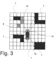
- the Fig.3 shows a schematic of a virtual sensor check of the grid map 12.
- a virtual sensor 13 is arranged at a position of the industrial truck 1 in the grid map 12.
- the static objects 7 are detected using virtual scanning beams 14.
- the dynamic object 8 is not detected and no sensor data is passed on to a vehicle control system, for example. This can be done by only detecting objects 7 with a weighting above a threshold value or with a maximum weighting.
Landscapes
- Engineering & Computer Science (AREA)
- Structural Engineering (AREA)
- Transportation (AREA)
- Automation & Control Theory (AREA)
- Physics & Mathematics (AREA)
- General Physics & Mathematics (AREA)
- Remote Sensing (AREA)
- Life Sciences & Earth Sciences (AREA)
- Geology (AREA)
- Mechanical Engineering (AREA)
- Radar, Positioning & Navigation (AREA)
- Aviation & Aerospace Engineering (AREA)
- Civil Engineering (AREA)
- Control Of Position, Course, Altitude, Or Attitude Of Moving Bodies (AREA)
- Traffic Control Systems (AREA)
Description
- Die Erfindung betrifft ein Verfahren zur Hinderniserfassung bei einem Flurförderzeug. Insbesondere betrifft die Erfindung ein Verfahren zur Erfassung von Hindernissen in der Umgebung eines Flurförderzeugs, vor allem eines für das Kommissionieren vorgesehenen Flurförderzeugs, wobei das Flurförderzeug zur Überwachung der Umgebung einen Sensor aufweist, der mit einer Steuerungsvorrichtung verbunden ist, und durch Auswertung der Daten des Sensors einen Überwachungsbereich erfasst. Ein solches Verfahren zur Erfassung von Hindernissen ist bekannt aus
US 2015 0120 125A . Unter den vielfältigen Einsatzmöglichkeiten für Flurförderzeugen ist auch das Zusammenstellen von Waren für eine Lieferung an einen Kunden, das Kommissionieren. Dabei werden in Lagerhäusern spezielle Flurförderzeuge eingesetzt, mit denen durch den Lagerbereich, beispielsweise durch Regalreihen gefahren wird. Solche Kommissionierflurförderzeuge können dabei so ausgelegt sein, dass eine Person während des Kommissionierens mitfährt, aber auch beim Zusammenstellen der Waren und beim Fahren an einem Regal entlang zu Fuß neben dem Flurförderzeug mitläuft, um Waren aus dem Regal zu entnehmen und diese auf eine Palette oder in einen Transportbehälter auf dem Flurförderzeug abzulegen. - Für die erleichterte Bedienung des Kommissionierflurförderzeugs sind dabei Fernbedienungen bekannt. Durch solche Fernbedienungen hat die kommissionierende Person, der Kommissionierer oder Bediener, die Möglichkeit, das Kommissionierflurförderzeug zu verlassen und dessen Fahrbewegungen mit der Fernbedienung anzusteuern. Eine bekannte Variante hierfür ist, dass der Kommissionierer durch einen Knopfdruck ein Vorwärtsfahren des Fahrzeugs anfordert, wobei das Kommissionierflurförderzeug so lange fährt, wie der Knopf gedrückt bleibt.
- Bekannt sind dabei Steuerungen zur automatischen Führung des Kommissionierflurförderzeugs, die auf in einem Regalgang sich befindende Hindernisse reagiert, indem das Flurförderzeug ausweicht. Verwendet werden für diese automatischen Fahrbewegungen häufig optische Sensoren, beispielsweise ein Laserscanner, mit dem Hindernisse bzw. Objekte im Regalgang erkannt werden können.
- Nachteilig an diesem Stand der Technik ist, dass das Ausweichen unabhängig davon erfolgt, ob und wie schnell sich ein Objekt als Hindernis bewegt. Daher kommt es dazu, dass das Flurförderzeug vor Hindernissen in der Bewegungsrichtung des Fahrzeuges stets bereits frühzeitig ausweicht, unabhängig davon, ob es sich dabei um statische oder sich bewegende Hindernisse handelt, mit der Folge ungewollter seitliche Ausweichbewegungen des Flurförderzeugs und von Zeitverlusten. Insbesondere führt dies dazu, dass auch ein Kommissionierer, der sich außerhalb des Flurförderzeugs befindet und den Erfassungsbereich des Sensors durchquert, bereits eine Ausweichbewegung verursachen kann. Es ist gerade beim Kommissionieren jedoch sehr häufig, dass der Kommissionierer einen solchen Bereich außerhalb einer engeren Kollisionssicherheitszone, jedoch innerhalb des Erfassungsbereichs des Sensors rasch durchquert, um möglichst effiziente und mit kurzen Laufwegen Waren zu erreichen.
- Weiterhin ist es auch wünschenswert, die Umgebung möglichst lückenlos zu erfassen im Bereich vor und um das Flurförderzeug. Nach dem bekannten Stand der Technik kann jedoch nur in der Hauptfahrrichtung, soweit der optische Sensor sehen kann, die Umgebung erfasst werden und es stehen keine Informationen für den durch Hindernisse oder Gegenstände verdeckten Bereich zur Verfügung.
- Der vorliegenden Erfindung liegt daher die Aufgabe zugrunde, ein Verfahren zur Erfassung von Hindernissen bei einem Flurförderzeug, insbesondere bei einem Flurförderzeug zur Kommissionierung, zur Verfügung zu stellen, dass die zuvor genannten Nachteile vermeidet und mit dem nicht unbedingt erforderliche Ausweichbewegungen vor Hindernissen im automatischen Betrieb vermieden werden.
- Diese Aufgabe wird durch ein Verfahren mit den Merkmalen des unabhängigen Patentanspruchs 1 gelöst. Vorteilhafte Weiterbildungen der Erfindung sind in den Unteransprüchen angegeben.
- Die Aufgabe wird erfindungsgemäß dadurch gelöst, dass bei einem Verfahren zur Erfassung von Hindernissen in der Umgebung eines Flurförderzeugs, insbesondere eines für das Kommissionieren vorgesehenen Flurförderzeugs, wobei das Flurförderzeug zur Überwachung der Umgebung einen Sensor aufweist, der mit einer Steuerungsvorrichtung verbunden ist, und durch Auswertung der Daten des Sensors einen Überwachungsbereich erfasst, in den Daten in der Umgebung des Flurförderzeug erfasste Objekte in eine Karte eingetragen werden sowie kontinuierlich der Überwachungsbereich erneut erfasst wird, wobei bei Objekten an derselben absoluten Position in der Karte eine Gewichtung erhöht wird und bei an derselben Position fehlenden Objekten die Gewichtung eines eingetragenen Objekts verringert wird bis hin zu einer Löschung des Objekts.
- Durch den Sensor, bei dem es sich um jegliche Art von für die Erfassung von Objekten in der Umgebung geeigneten Sensor handeln kann, bevorzugt einen optischen Sensor, werden Bildpunkte bzw. Daten erfasst und mit bekannten Methoden der Auswertung, insbesondere der Bildverarbeitung, als Hindernisse bzw. Objekte erkannt. Diese werden in eine Karte eingetragen. Die Erfassung der Daten durch den Sensor erfolgt sich kontinuierlich wiederholend, beispielsweise bei einem Laserscanner mit jedem Umlauf des Laserstrahls. Es ergibt sich somit eine Abfolge von Datensätzen, wobei in der Karte ein Objekt, das erneut an derselben Stelle sich befindet, höher gewichtet wird, und ein Objekt das an dieser Stelle nicht mehr vorhanden ist, in der Gewichtung herabgesetzt wird. Dies kann erfolgen, indem von einem herabgesetzt wird. Dies kann erfolgen, indem von einem ersten Eintragswert bis zu einem Maximalwert in einer bestimmten Anzahl von Schritten die Gewichtung jeweils erhöht wird. Dadurch wird beispielsweise eine sich schnell bewegende Person in einem ersten Schritt in der Karte an einer Stelle als Objekt mit dem kleinsten Wert eingetragen und de sie beim folgenden Datensatz bereits nicht mehr an dieser Stelle ist, wird dieses Objekt in einem zweiten Schritt gleich wieder ausgetragen, da um denselben Wert wieder heruntergewichtet. In der Folge wird es möglich, zwischen relevanten, statischen Objekten als Hindernissen und auf der anderen Seite nicht relevanten, dynamischen Hindernissen zu unterscheiden. Dies kann beispielsweise anhand eines Schwellenwerts für die Gewichtung erfolgen oder auch, wenn als statische Objekte nur solche Objekte angesehen werden, die eine maximale Gewichtung erreicht haben. Es ergibt sich kein ungewolltes Ausweichen bei durch einen Überwachungsbereich laufenden Personen sowie vorbelfahrenden anderen Fahrzeugen, wenn nur die relevanten Objekte als Hindernisse betrachtet werden.
- Vorteilhaft ist die Karte eine Gitternetzkarte.
- In eine solche Gitternetzkarte, auch bezeichnet Gridmap, werden Objekte mit einem Wert in die Gitterfelder eingetragen.
- In einer günstigen Ausgestaltung des Verfahrens ist die Karte eine ortsfeste, globale Karte.
- Diese Karte ist beispielsweise ortsfest gegenüber einem Lager oder einem Teilbereich eines Lagers, in dem sich das Flurförderzeug bewegt.
- Die Karte kann eine relativ auf das Flurförderzeug bezogene Karte sein.
- Die Karte bewegt sich hier mit dem Flurförderzeug mit, wobei die relative Ortsveränderung der Einträge in der Karte aufgrund der Fahrbewegungen des Flurförderzeugs korrigiert und mitgerechnet werden kann.
- Es werden durch einen virtuellen Sensor, der in der Karte positioniert ist, Sensordaten über Hindernisse in der Umgebung des Flurförderzeugs aus der Karte erfasst und an eine Fahrzeugsteuerung geleitet.
- Dieser virtuelle Sensor, der beispielsweise von einem Steuerungscomputer umgesetzt werden kann, kann eine frei wähibare Modellierung aufweisen in Bezug auf einen Öffnungswinkel, eine Auflösung sowie eine Reichweite virtuell auszusendender Abtaststrahlen. Der virtuelle Sensor wird frei in der Karte positioniert und liefert Sensordaten über Hindernisse. Dabei können auch Hindernisse bzw. Objekte außerhalb des Überwachungsbereichs des tatsächlichen Sensors erfasst werden, da die Reichweite größer gefasst sein kann und insbesondere auch durch Hindernisse verdeckte Objekte erfasst werden können. In den virtuellen Sensordaten sind keine Informationen über dynamische Objekte enthalten bzw werden diese besonders markiert. Wenn die virtuellen Sensordaten daher durch eine Fahrzeugsteuerung für das automatische Fahren des Flurförderzeugs eingesetzt werden, so kommt es nicht zu ungewollten Ausweichbewegungen aufgrund dynamischer Objekte, wie etwa einer durch den Überwachungsbereich laufenden Person.
- In einer Ausgestaltung des Verfahrens ist der virtuelle Sensor an der Position des Flurförderzeugs in der Karte angeordnet
- Dadurch hat der virtuelle Sensor denselben Blickwinkel wie der tatsächliche Sensor auf dem Flurförderzeug. Dieser kann beispielsweise ausgerichtet sein in Fahrtrichtung nach vorne.
- Der Sensor ist ein Laserscanner.
- Für die Auswertung der Daten des Sensors können die nach dem Stand der Technik bekannten Methoden der digitalen Bildverarbeitung Bilderkennung eingesetzt wird. Durch das zuvor beschriebene Verfahren wird es auch möglich die Bewegung dynamischer Objekte in der Karte zu Verfolgen.
- Weitere Vorteile und Einzelheiten der Erfindung werden anhand des in den schematischen Figuren dargestellten Ausführungsbeispieis näher erläutert. Hierbei zeigt
- Fig. 1
- schematisch ein Flurförderzeug mit einem Kommissionierer und weiteren Hindernissen, bei dem das erfindungsgemäße Verfahren durchgeführt wird,
- Fig. 2
- schematisch eine Gitternetzkarte zur Erfassung von Objekten in der Umgebung des Flurförderzeugs der
Fig. 1 und - Fig. 3
- schematisch eine virtuelle Sensorüberprüfung der Gitternetzkarte.
- Die
Fig. 1 zeigt schematisch ein Flurförderzeug 1, dass sich selbst in Richtung des dargestellten Pfeils bewegt, bei dem das erfindungsgemäße Verfahren durchgeführt wird, mit einer Person als Kommissionierer 2 und weiteren Hindernissen 3, beispielsweise Paletten mit Waren. Ein Sensor 4 in Form eines Laserscanners 5 erfasst durch Laserstrahlen 6 die statischen Hindernisse 3 als statische Objekte 7 und den Kommissionierer 2 als dynamisches Objekt 8, das sich wie durch den Pfeil angedeutet bewegt, in einem Überwachungsraum 9 des Flurförderzeugs 1. - Die
Fig. 2 zeigt schematisch eine Karte 10 in Form einer Gitternetzkarte 11 bzw. Gridmap zur Erfassung von Objekten 7,8 in der Umgebung des Flurförderzeugs 1 derFig. 1 . dabei sind die statischen Objekte 7 dunkler eingetragen in der Darstellung, entsprechend einer höheren oder maximalen Gewichtung. Dies kann beispielsweise einem hohen Zahlenwert entsprechen, der einem Feld der Gitternetzkarte zugeordnet wird. Die dynamischen Objekte 8 in der Karte 10 entsprechen den nacheinander eingenommenen Positionen des Kommissionlerers 2 in derFig. 1 und sind in einem helleren Grautung. - Die
Fig. 3 zeigt schematisch eine virtuelle Sensorüberprüfung der Gitternetzkarte 12. Ein virtueller Sensor 13 ist an einer Position des Flurförderzeug 1 in der Gitternetzkarte 12 angeordnet. Mithilfe von virtuellen Abtaststrahlen 14 werden die statischen Objekte 7 erfasst. Das dynamische Objekt 8 wird nicht erfasst und über dieses werden keine Sensordaten beispielsweise an eine Fahrzeugsteuerung weitergegeben. Dies kann dadurch erfolgen, dass nur Objekte 7 mit einer Gewichtung oberhalb eines Schwellenwertes oder mit Maximalgewichtung erfasst werden.
Claims (5)
- Verfahren zur Erfassung von Hindernissen (3) in der Umgebung eines Flurförderzeugs (1), insbesondere eines für das Kommissionieren vorgesehenen Flurförderzeugs(1), wobei das Flurförderzeug (1) zur Überwachung der Umgebung einen Sensor (4) aufweist, der mit einer Steuerungsvorrichtung verbunden ist, und durch Auswertung der Daten des Sensors (4) einen Überwachungsbereich (9) erfasst,
wobei in den Daten in der Umgebung des Flurförderzeug (1) erfasste Objekte (7,8) in eine Karte (10) eingetragen werden sowie kontinuierlich der Überwachungsbereich (6) erneut erfasst wird, dadurch gekennzeichnet, dass bei Objekten (7) an derselben absoluten Position in der Karte eine Gewichtung erhöht wird und bei an derselben Position fehlenden Objekten (8) die Gewichtung eines eingetragenen Objekts (8) verringert wird bis hin zu einer Löschung des Objekts (8), wobei der Sensor (4) ein Laserscanner (5) ist, und dadurch gekennzeichnet, dass durch einen virtuellen Sensor (13), der in der Karte (10) positioniert ist, Sensordaten über Hindernisse in der Umgebung des Flurförderzeugs (1) aus der Karte (10) erfasst werden und an eine Fahrzeugsteuerung geleitet werden. - Verfahren nach Anspruch 1,
dadurch gekennzeichnet,
dass die Karte (10) eine Gitternetzkarte (12) ist. - Verfahren nach Anspruch 1 oder 2,
dadurch gekennzeichnet,
dass die Karte (10) eine ortsfeste, globale Karte ist. - Verfahren nach Anspruch 1 oder 2,
dadurch gekennzeichnet,
dass die Karte (10) eine relativ auf das Flurförderzeug (1) bezogene Karte ist. - Verfahren nach einem der Ansprüche 1 bis 4,
dadurch gekennzeichnet,
dass der virtuelle Sensor (13) an der Position des Flurförderzeugs (1) in der Karte (10) angeordnet ist.
Applications Claiming Priority (1)
| Application Number | Priority Date | Filing Date | Title |
|---|---|---|---|
| DE102015111613.8A DE102015111613A1 (de) | 2015-07-17 | 2015-07-17 | Verfahren zur Hinderniserfassung bei einem Flurförderzeug |
Publications (4)
| Publication Number | Publication Date |
|---|---|
| EP3118153A1 EP3118153A1 (de) | 2017-01-18 |
| EP3118153B1 EP3118153B1 (de) | 2018-04-11 |
| EP3118153B9 EP3118153B9 (de) | 2018-09-12 |
| EP3118153B2 true EP3118153B2 (de) | 2024-09-25 |
Family
ID=56292623
Family Applications (1)
| Application Number | Title | Priority Date | Filing Date |
|---|---|---|---|
| EP16177593.7A Active EP3118153B2 (de) | 2015-07-17 | 2016-07-01 | Verfahren zur hinderniserfassung bei einem flurförderzeug |
Country Status (2)
| Country | Link |
|---|---|
| EP (1) | EP3118153B2 (de) |
| DE (1) | DE102015111613A1 (de) |
Families Citing this family (4)
| Publication number | Priority date | Publication date | Assignee | Title |
|---|---|---|---|---|
| DE102018100758A1 (de) | 2018-01-15 | 2019-07-18 | Jungheinrich Aktiengesellschaft | Verfahren zur Steuerung eines Flurförderzeugs sowie ein System aus einer übergeordneten Steuereinheit und einem Fluförderzeug |
| US12221330B2 (en) | 2020-02-21 | 2025-02-11 | Crown Equipment Corporation | Lighting floor on sides of material handling vehicle to indicate limited or non-limited area |
| DE102020105334A1 (de) | 2020-02-28 | 2021-09-02 | Viatcheslav Tretyakov | Verfahren für ein Steuern eines fahrerlosen Transportfahrzeugs und Steuerungssystem, das angepasst ist, um das Verfahren auszuführen |
| DE102021130254A1 (de) | 2021-11-19 | 2023-05-25 | Jungheinrich Aktiengesellschaft | Verfahren zum handhaben von störungen in flurförderzeugen |
Family Cites Families (9)
| Publication number | Priority date | Publication date | Assignee | Title |
|---|---|---|---|---|
| DE4408329C2 (de) | 1994-03-11 | 1996-04-18 | Siemens Ag | Verfahren zum Aufbau einer zellular strukturierten Umgebungskarte von einer selbstbeweglichen mobilen Einheit, welche sich mit Hilfe von auf Wellenreflexion basierenden Sensoren orientiert |
| US7584020B2 (en) | 2006-07-05 | 2009-09-01 | Battelle Energy Alliance, Llc | Occupancy change detection system and method |
| CN102576228A (zh) | 2009-08-31 | 2012-07-11 | Neato机器人技术公司 | 移动机器人环境的同时定位和地图绘制的方法和设备 |
| EP2797832B1 (de) | 2011-12-30 | 2025-02-05 | Seegrid Corporation | Selbstnavigierendes fahrzeug mit sichtfeldoptimierender sensorpositionierung und verfahren zum erhalt |
| US8965561B2 (en) | 2013-03-15 | 2015-02-24 | Cybernet Systems Corporation | Automated warehousing using robotic forklifts |
| DE202013004209U1 (de) | 2013-05-07 | 2013-07-25 | Ralf Bär | Fahrerloses Transportfahrzeug, insbesondere für die Materialbereitstellung an Montagelinien |
| DE102013211126A1 (de) | 2013-06-14 | 2014-12-18 | Robert Bosch Gmbh | Verfahren zum Modellieren eines Umfelds eines Fahrzeugs |
| US9354070B2 (en) | 2013-10-31 | 2016-05-31 | Crown Equipment Corporation | Systems, methods, and industrial vehicles for determining the visibility of features |
| DE102014200279A1 (de) | 2014-01-10 | 2015-07-16 | Robert Bosch Gmbh | Verfahren und Vorrichtung zum Detektieren von Objekten in einem Umfeld eines Fahrzeugs |
-
2015
- 2015-07-17 DE DE102015111613.8A patent/DE102015111613A1/de active Pending
-
2016
- 2016-07-01 EP EP16177593.7A patent/EP3118153B2/de active Active
Also Published As
| Publication number | Publication date |
|---|---|
| DE102015111613A1 (de) | 2017-01-19 |
| EP3118153A1 (de) | 2017-01-18 |
| EP3118153B9 (de) | 2018-09-12 |
| EP3118153B1 (de) | 2018-04-11 |
Similar Documents
| Publication | Publication Date | Title |
|---|---|---|
| EP3323770B1 (de) | Verfahren zur bereitstellung der positionen von lagerplätzen in einem lager und flurförderzeug | |
| EP2851331B1 (de) | Verfahren zur Steuerung eines Kommissionierflurförderzeugs | |
| DE112010003000B4 (de) | Sichtsystem zum Überwachen von Menschen in dynamischen Umgebungen | |
| EP3118153B2 (de) | Verfahren zur hinderniserfassung bei einem flurförderzeug | |
| EP3316181B1 (de) | Verfahren zum erkennen von objekten in einem lager und flurförderzeug mit einer einrichtung zum erkennen von objekten in einem lager | |
| DE102015211761B4 (de) | Überwachungssystem für einen Kommissionierarbeitsplatz und Verfahren zum Kommissionieren | |
| DE102018205964A1 (de) | Verfahren und Steuergerät zum Navigieren eines autonomen Flurförderfahrzeugs | |
| EP3118152B1 (de) | Verfahren zur geschwindigkeitssteuerung eines kommissionierflurförderzeugs | |
| DE102012108034A1 (de) | Steuerungsverfahren für Flurförderzeug sowie Flurförderzeug | |
| EP3981731B1 (de) | Verfahren zur bestimmung von abstandswerten zu einem flurförderzeug sowie ein solches | |
| DE102015111697A1 (de) | Verfahren zur Steuerung eines Kommissionierflurförderzeugs | |
| DE102017120996A1 (de) | Verfahren und Vorrichtung zur Kollisionsvermeidung beim Betrieb eines Flurförderzeugs | |
| DE102012108028A1 (de) | Steuerverfahren für Lastabsetzung eines Flurförderzeugs sowie Flurförderzeug | |
| DE102015113445A1 (de) | Verfahren zur Geschwindigkeitssteuerung eines Kommissionierflurförderzeugs | |
| EP3977225B1 (de) | Verfahren zur erstellung einer umgebungskarte für die verwendung bei der autonomen navigation eines mobilen roboters | |
| EP2385014A1 (de) | Flurförderzeug mit einer Einrichtung zur Identifizierung eines geladenen Transportgutes, und Verfahren zur Identifizierung eines geladenen Transportgutes eines Flurförderzeugs | |
| EP2107336A1 (de) | Verfahren und Vorrichtung zur Bilderkennung von bewegten Objekten, wie etwa in Förderanlagen | |
| EP3947246B1 (de) | Verfahren zur lagerungsunterstützung bei einem flurförderzeug und flurförderzeug | |
| DE102014113264A1 (de) | Steuersystem für einen Kommissionier-Arbeitsplatz und Verfahren zum Kommissionieren | |
| EP3476793B1 (de) | Betrieb eines flurförderzeugs und entsprechendes flurförderzeug | |
| WO2020200537A1 (de) | Verfahren und system zur identifikation von schüttgut | |
| DE102013012908A1 (de) | Kommissioniersystem | |
| DE102013112016B4 (de) | Flurförderzeug mit einem Hubhöhenassistenzsystem | |
| EP3118707B1 (de) | Verfahren zur fahrsteuerung eines kommissionierflurförderzeug | |
| DE102023125123B4 (de) | Verfahren zum Betreiben eines Flurförderzeugs in einem Lager und Flurförderzeug |
Legal Events
| Date | Code | Title | Description |
|---|---|---|---|
| PUAI | Public reference made under article 153(3) epc to a published international application that has entered the european phase |
Free format text: ORIGINAL CODE: 0009012 |
|
| STAA | Information on the status of an ep patent application or granted ep patent |
Free format text: STATUS: THE APPLICATION HAS BEEN PUBLISHED |
|
| AK | Designated contracting states |
Kind code of ref document: A1 Designated state(s): AL AT BE BG CH CY CZ DE DK EE ES FI FR GB GR HR HU IE IS IT LI LT LU LV MC MK MT NL NO PL PT RO RS SE SI SK SM TR |
|
| AX | Request for extension of the european patent |
Extension state: BA ME |
|
| STAA | Information on the status of an ep patent application or granted ep patent |
Free format text: STATUS: REQUEST FOR EXAMINATION WAS MADE |
|
| 17P | Request for examination filed |
Effective date: 20170622 |
|
| RBV | Designated contracting states (corrected) |
Designated state(s): AL AT BE BG CH CY CZ DE DK EE ES FI FR GB GR HR HU IE IS IT LI LT LU LV MC MK MT NL NO PL PT RO RS SE SI SK SM TR |
|
| GRAP | Despatch of communication of intention to grant a patent |
Free format text: ORIGINAL CODE: EPIDOSNIGR1 |
|
| STAA | Information on the status of an ep patent application or granted ep patent |
Free format text: STATUS: GRANT OF PATENT IS INTENDED |
|
| INTG | Intention to grant announced |
Effective date: 20171215 |
|
| GRAS | Grant fee paid |
Free format text: ORIGINAL CODE: EPIDOSNIGR3 |
|
| GRAA | (expected) grant |
Free format text: ORIGINAL CODE: 0009210 |
|
| STAA | Information on the status of an ep patent application or granted ep patent |
Free format text: STATUS: THE PATENT HAS BEEN GRANTED |
|
| AK | Designated contracting states |
Kind code of ref document: B1 Designated state(s): AL AT BE BG CH CY CZ DE DK EE ES FI FR GB GR HR HU IE IS IT LI LT LU LV MC MK MT NL NO PL PT RO RS SE SI SK SM TR |
|
| REG | Reference to a national code |
Ref country code: GB Ref legal event code: FG4D Free format text: NOT ENGLISH |
|
| REG | Reference to a national code |
Ref country code: CH Ref legal event code: EP |
|
| REG | Reference to a national code |
Ref country code: AT Ref legal event code: REF Ref document number: 987806 Country of ref document: AT Kind code of ref document: T Effective date: 20180415 |
|
| REG | Reference to a national code |
Ref country code: IE Ref legal event code: FG4D Free format text: LANGUAGE OF EP DOCUMENT: GERMAN |
|
| REG | Reference to a national code |
Ref country code: DE Ref legal event code: R096 Ref document number: 502016000824 Country of ref document: DE |
|
| REG | Reference to a national code |
Ref country code: FR Ref legal event code: PLFP Year of fee payment: 3 |
|
| REG | Reference to a national code |
Ref country code: SE Ref legal event code: TRGR |
|
| REG | Reference to a national code |
Ref country code: NL Ref legal event code: MP Effective date: 20180411 |
|
| REG | Reference to a national code |
Ref country code: LT Ref legal event code: MG4D |
|
| REG | Reference to a national code |
Ref country code: CH Ref legal event code: PK Free format text: BERICHTIGUNG B9 |
|
| PG25 | Lapsed in a contracting state [announced via postgrant information from national office to epo] |
Ref country code: NL Free format text: LAPSE BECAUSE OF FAILURE TO SUBMIT A TRANSLATION OF THE DESCRIPTION OR TO PAY THE FEE WITHIN THE PRESCRIBED TIME-LIMIT Effective date: 20180411 |
|
| PG25 | Lapsed in a contracting state [announced via postgrant information from national office to epo] |
Ref country code: LT Free format text: LAPSE BECAUSE OF FAILURE TO SUBMIT A TRANSLATION OF THE DESCRIPTION OR TO PAY THE FEE WITHIN THE PRESCRIBED TIME-LIMIT Effective date: 20180411 Ref country code: PL Free format text: LAPSE BECAUSE OF FAILURE TO SUBMIT A TRANSLATION OF THE DESCRIPTION OR TO PAY THE FEE WITHIN THE PRESCRIBED TIME-LIMIT Effective date: 20180411 Ref country code: ES Free format text: LAPSE BECAUSE OF FAILURE TO SUBMIT A TRANSLATION OF THE DESCRIPTION OR TO PAY THE FEE WITHIN THE PRESCRIBED TIME-LIMIT Effective date: 20180411 Ref country code: BG Free format text: LAPSE BECAUSE OF FAILURE TO SUBMIT A TRANSLATION OF THE DESCRIPTION OR TO PAY THE FEE WITHIN THE PRESCRIBED TIME-LIMIT Effective date: 20180711 Ref country code: NO Free format text: LAPSE BECAUSE OF FAILURE TO SUBMIT A TRANSLATION OF THE DESCRIPTION OR TO PAY THE FEE WITHIN THE PRESCRIBED TIME-LIMIT Effective date: 20180711 Ref country code: FI Free format text: LAPSE BECAUSE OF FAILURE TO SUBMIT A TRANSLATION OF THE DESCRIPTION OR TO PAY THE FEE WITHIN THE PRESCRIBED TIME-LIMIT Effective date: 20180411 Ref country code: AL Free format text: LAPSE BECAUSE OF FAILURE TO SUBMIT A TRANSLATION OF THE DESCRIPTION OR TO PAY THE FEE WITHIN THE PRESCRIBED TIME-LIMIT Effective date: 20180411 |
|
| PG25 | Lapsed in a contracting state [announced via postgrant information from national office to epo] |
Ref country code: LV Free format text: LAPSE BECAUSE OF FAILURE TO SUBMIT A TRANSLATION OF THE DESCRIPTION OR TO PAY THE FEE WITHIN THE PRESCRIBED TIME-LIMIT Effective date: 20180411 Ref country code: RS Free format text: LAPSE BECAUSE OF FAILURE TO SUBMIT A TRANSLATION OF THE DESCRIPTION OR TO PAY THE FEE WITHIN THE PRESCRIBED TIME-LIMIT Effective date: 20180411 Ref country code: HR Free format text: LAPSE BECAUSE OF FAILURE TO SUBMIT A TRANSLATION OF THE DESCRIPTION OR TO PAY THE FEE WITHIN THE PRESCRIBED TIME-LIMIT Effective date: 20180411 Ref country code: GR Free format text: LAPSE BECAUSE OF FAILURE TO SUBMIT A TRANSLATION OF THE DESCRIPTION OR TO PAY THE FEE WITHIN THE PRESCRIBED TIME-LIMIT Effective date: 20180712 |
|
| PG25 | Lapsed in a contracting state [announced via postgrant information from national office to epo] |
Ref country code: PT Free format text: LAPSE BECAUSE OF FAILURE TO SUBMIT A TRANSLATION OF THE DESCRIPTION OR TO PAY THE FEE WITHIN THE PRESCRIBED TIME-LIMIT Effective date: 20180813 |
|
| REG | Reference to a national code |
Ref country code: DE Ref legal event code: R026 Ref document number: 502016000824 Country of ref document: DE |
|
| PLBI | Opposition filed |
Free format text: ORIGINAL CODE: 0009260 |
|
| PG25 | Lapsed in a contracting state [announced via postgrant information from national office to epo] |
Ref country code: DK Free format text: LAPSE BECAUSE OF FAILURE TO SUBMIT A TRANSLATION OF THE DESCRIPTION OR TO PAY THE FEE WITHIN THE PRESCRIBED TIME-LIMIT Effective date: 20180411 Ref country code: RO Free format text: LAPSE BECAUSE OF FAILURE TO SUBMIT A TRANSLATION OF THE DESCRIPTION OR TO PAY THE FEE WITHIN THE PRESCRIBED TIME-LIMIT Effective date: 20180411 Ref country code: SK Free format text: LAPSE BECAUSE OF FAILURE TO SUBMIT A TRANSLATION OF THE DESCRIPTION OR TO PAY THE FEE WITHIN THE PRESCRIBED TIME-LIMIT Effective date: 20180411 Ref country code: CZ Free format text: LAPSE BECAUSE OF FAILURE TO SUBMIT A TRANSLATION OF THE DESCRIPTION OR TO PAY THE FEE WITHIN THE PRESCRIBED TIME-LIMIT Effective date: 20180411 Ref country code: EE Free format text: LAPSE BECAUSE OF FAILURE TO SUBMIT A TRANSLATION OF THE DESCRIPTION OR TO PAY THE FEE WITHIN THE PRESCRIBED TIME-LIMIT Effective date: 20180411 |
|
| PLAX | Notice of opposition and request to file observation + time limit sent |
Free format text: ORIGINAL CODE: EPIDOSNOBS2 |
|
| 26 | Opposition filed |
Opponent name: STRAWMAN LIMITED Effective date: 20190109 |
|
| PG25 | Lapsed in a contracting state [announced via postgrant information from national office to epo] |
Ref country code: IT Free format text: LAPSE BECAUSE OF FAILURE TO SUBMIT A TRANSLATION OF THE DESCRIPTION OR TO PAY THE FEE WITHIN THE PRESCRIBED TIME-LIMIT Effective date: 20180411 Ref country code: SM Free format text: LAPSE BECAUSE OF FAILURE TO SUBMIT A TRANSLATION OF THE DESCRIPTION OR TO PAY THE FEE WITHIN THE PRESCRIBED TIME-LIMIT Effective date: 20180411 |
|
| PG25 | Lapsed in a contracting state [announced via postgrant information from national office to epo] |
Ref country code: LU Free format text: LAPSE BECAUSE OF NON-PAYMENT OF DUE FEES Effective date: 20180701 Ref country code: MC Free format text: LAPSE BECAUSE OF FAILURE TO SUBMIT A TRANSLATION OF THE DESCRIPTION OR TO PAY THE FEE WITHIN THE PRESCRIBED TIME-LIMIT Effective date: 20180411 |
|
| REG | Reference to a national code |
Ref country code: BE Ref legal event code: MM Effective date: 20180731 |
|
| REG | Reference to a national code |
Ref country code: IE Ref legal event code: MM4A |
|
| PG25 | Lapsed in a contracting state [announced via postgrant information from national office to epo] |
Ref country code: IE Free format text: LAPSE BECAUSE OF NON-PAYMENT OF DUE FEES Effective date: 20180701 |
|
| PG25 | Lapsed in a contracting state [announced via postgrant information from national office to epo] |
Ref country code: SI Free format text: LAPSE BECAUSE OF FAILURE TO SUBMIT A TRANSLATION OF THE DESCRIPTION OR TO PAY THE FEE WITHIN THE PRESCRIBED TIME-LIMIT Effective date: 20180411 Ref country code: BE Free format text: LAPSE BECAUSE OF NON-PAYMENT OF DUE FEES Effective date: 20180731 |
|
| PLBB | Reply of patent proprietor to notice(s) of opposition received |
Free format text: ORIGINAL CODE: EPIDOSNOBS3 |
|
| PG25 | Lapsed in a contracting state [announced via postgrant information from national office to epo] |
Ref country code: MT Free format text: LAPSE BECAUSE OF FAILURE TO SUBMIT A TRANSLATION OF THE DESCRIPTION OR TO PAY THE FEE WITHIN THE PRESCRIBED TIME-LIMIT Effective date: 20180411 |
|
| REG | Reference to a national code |
Ref country code: CH Ref legal event code: PL |
|
| PG25 | Lapsed in a contracting state [announced via postgrant information from national office to epo] |
Ref country code: TR Free format text: LAPSE BECAUSE OF FAILURE TO SUBMIT A TRANSLATION OF THE DESCRIPTION OR TO PAY THE FEE WITHIN THE PRESCRIBED TIME-LIMIT Effective date: 20180411 |
|
| PG25 | Lapsed in a contracting state [announced via postgrant information from national office to epo] |
Ref country code: LI Free format text: LAPSE BECAUSE OF NON-PAYMENT OF DUE FEES Effective date: 20190731 Ref country code: CH Free format text: LAPSE BECAUSE OF NON-PAYMENT OF DUE FEES Effective date: 20190731 |
|
| PG25 | Lapsed in a contracting state [announced via postgrant information from national office to epo] |
Ref country code: MK Free format text: LAPSE BECAUSE OF NON-PAYMENT OF DUE FEES Effective date: 20180411 Ref country code: HU Free format text: LAPSE BECAUSE OF FAILURE TO SUBMIT A TRANSLATION OF THE DESCRIPTION OR TO PAY THE FEE WITHIN THE PRESCRIBED TIME-LIMIT; INVALID AB INITIO Effective date: 20160701 Ref country code: CY Free format text: LAPSE BECAUSE OF FAILURE TO SUBMIT A TRANSLATION OF THE DESCRIPTION OR TO PAY THE FEE WITHIN THE PRESCRIBED TIME-LIMIT Effective date: 20180411 |
|
| PG25 | Lapsed in a contracting state [announced via postgrant information from national office to epo] |
Ref country code: IS Free format text: LAPSE BECAUSE OF FAILURE TO SUBMIT A TRANSLATION OF THE DESCRIPTION OR TO PAY THE FEE WITHIN THE PRESCRIBED TIME-LIMIT Effective date: 20180811 |
|
| GBPC | Gb: european patent ceased through non-payment of renewal fee |
Effective date: 20200701 |
|
| PG25 | Lapsed in a contracting state [announced via postgrant information from national office to epo] |
Ref country code: GB Free format text: LAPSE BECAUSE OF NON-PAYMENT OF DUE FEES Effective date: 20200701 |
|
| RIC2 | Information provided on ipc code assigned after grant |
Ipc: B66F 17/00 20060101AFI20210518BHEP Ipc: B66F 9/06 20060101ALI20210518BHEP Ipc: B66F 9/075 20060101ALI20210518BHEP |
|
| APAH | Appeal reference modified |
Free format text: ORIGINAL CODE: EPIDOSCREFNO |
|
| APBM | Appeal reference recorded |
Free format text: ORIGINAL CODE: EPIDOSNREFNO |
|
| APBP | Date of receipt of notice of appeal recorded |
Free format text: ORIGINAL CODE: EPIDOSNNOA2O |
|
| APBQ | Date of receipt of statement of grounds of appeal recorded |
Free format text: ORIGINAL CODE: EPIDOSNNOA3O |
|
| REG | Reference to a national code |
Ref country code: AT Ref legal event code: MM01 Ref document number: 987806 Country of ref document: AT Kind code of ref document: T Effective date: 20210701 |
|
| PG25 | Lapsed in a contracting state [announced via postgrant information from national office to epo] |
Ref country code: AT Free format text: LAPSE BECAUSE OF NON-PAYMENT OF DUE FEES Effective date: 20210701 |
|
| P01 | Opt-out of the competence of the unified patent court (upc) registered |
Effective date: 20230518 |
|
| APBU | Appeal procedure closed |
Free format text: ORIGINAL CODE: EPIDOSNNOA9O |
|
| PUAH | Patent maintained in amended form |
Free format text: ORIGINAL CODE: 0009272 |
|
| STAA | Information on the status of an ep patent application or granted ep patent |
Free format text: STATUS: PATENT MAINTAINED AS AMENDED |
|
| 27A | Patent maintained in amended form |
Effective date: 20240925 |
|
| AK | Designated contracting states |
Kind code of ref document: B2 Designated state(s): AL AT BE BG CH CY CZ DE DK EE ES FI FR GB GR HR HU IE IS IT LI LT LU LV MC MK MT NL NO PL PT RO RS SE SI SK SM TR |
|
| REG | Reference to a national code |
Ref country code: DE Ref legal event code: R102 Ref document number: 502016000824 Country of ref document: DE |
|
| REG | Reference to a national code |
Ref country code: SE Ref legal event code: RPEO |
|
| PGFP | Annual fee paid to national office [announced via postgrant information from national office to epo] |
Ref country code: DE Payment date: 20250722 Year of fee payment: 10 |
|
| PGFP | Annual fee paid to national office [announced via postgrant information from national office to epo] |
Ref country code: FR Payment date: 20250723 Year of fee payment: 10 |
|
| PGFP | Annual fee paid to national office [announced via postgrant information from national office to epo] |
Ref country code: SE Payment date: 20250723 Year of fee payment: 10 |