EP3117545B1 - Method and arrangement for configuring csi measurements - Google Patents
Method and arrangement for configuring csi measurements Download PDFInfo
- Publication number
- EP3117545B1 EP3117545B1 EP14838341.7A EP14838341A EP3117545B1 EP 3117545 B1 EP3117545 B1 EP 3117545B1 EP 14838341 A EP14838341 A EP 14838341A EP 3117545 B1 EP3117545 B1 EP 3117545B1
- Authority
- EP
- European Patent Office
- Prior art keywords
- csi
- wireless device
- resource
- network node
- measurements
- Prior art date
- Legal status (The legal status is an assumption and is not a legal conclusion. Google has not performed a legal analysis and makes no representation as to the accuracy of the status listed.)
- Active
Links
- 238000005259 measurement Methods 0.000 title claims description 90
- 238000000034 method Methods 0.000 title claims description 78
- 230000008569 process Effects 0.000 claims description 36
- 230000005540 biological transmission Effects 0.000 claims description 31
- 230000003068 static effect Effects 0.000 claims description 18
- 238000012935 Averaging Methods 0.000 claims description 9
- 230000001419 dependent effect Effects 0.000 claims description 8
- 230000006978 adaptation Effects 0.000 claims description 4
- 238000010586 diagram Methods 0.000 description 7
- 238000004590 computer program Methods 0.000 description 4
- 239000013256 coordination polymer Substances 0.000 description 4
- 238000013468 resource allocation Methods 0.000 description 4
- 238000004891 communication Methods 0.000 description 3
- 230000011664 signaling Effects 0.000 description 3
- 238000012546 transfer Methods 0.000 description 3
- 101150071746 Pbsn gene Proteins 0.000 description 2
- 230000008901 benefit Effects 0.000 description 2
- 238000013507 mapping Methods 0.000 description 2
- 230000007246 mechanism Effects 0.000 description 2
- 101000741965 Homo sapiens Inactive tyrosine-protein kinase PRAG1 Proteins 0.000 description 1
- 101001018494 Homo sapiens Pro-MCH Proteins 0.000 description 1
- 102100038659 Inactive tyrosine-protein kinase PRAG1 Human genes 0.000 description 1
- 102100033721 Pro-MCH Human genes 0.000 description 1
- 230000002776 aggregation Effects 0.000 description 1
- 238000004220 aggregation Methods 0.000 description 1
- 230000006399 behavior Effects 0.000 description 1
- 230000001427 coherent effect Effects 0.000 description 1
- 238000005516 engineering process Methods 0.000 description 1
- 230000007774 longterm Effects 0.000 description 1
- 238000010295 mobile communication Methods 0.000 description 1
- 230000004044 response Effects 0.000 description 1
- 230000002441 reversible effect Effects 0.000 description 1
Images


Classifications
-
- H—ELECTRICITY
- H04—ELECTRIC COMMUNICATION TECHNIQUE
- H04W—WIRELESS COMMUNICATION NETWORKS
- H04W72/00—Local resource management
- H04W72/04—Wireless resource allocation
- H04W72/044—Wireless resource allocation based on the type of the allocated resource
- H04W72/0446—Resources in time domain, e.g. slots or frames
-
- H—ELECTRICITY
- H04—ELECTRIC COMMUNICATION TECHNIQUE
- H04L—TRANSMISSION OF DIGITAL INFORMATION, e.g. TELEGRAPHIC COMMUNICATION
- H04L1/00—Arrangements for detecting or preventing errors in the information received
- H04L1/0001—Systems modifying transmission characteristics according to link quality, e.g. power backoff
- H04L1/0023—Systems modifying transmission characteristics according to link quality, e.g. power backoff characterised by the signalling
- H04L1/0026—Transmission of channel quality indication
-
- H—ELECTRICITY
- H04—ELECTRIC COMMUNICATION TECHNIQUE
- H04L—TRANSMISSION OF DIGITAL INFORMATION, e.g. TELEGRAPHIC COMMUNICATION
- H04L5/00—Arrangements affording multiple use of the transmission path
- H04L5/003—Arrangements for allocating sub-channels of the transmission path
- H04L5/0048—Allocation of pilot signals, i.e. of signals known to the receiver
-
- H—ELECTRICITY
- H04—ELECTRIC COMMUNICATION TECHNIQUE
- H04W—WIRELESS COMMUNICATION NETWORKS
- H04W24/00—Supervisory, monitoring or testing arrangements
- H04W24/10—Scheduling measurement reports ; Arrangements for measurement reports
-
- H—ELECTRICITY
- H04—ELECTRIC COMMUNICATION TECHNIQUE
- H04W—WIRELESS COMMUNICATION NETWORKS
- H04W72/00—Local resource management
- H04W72/20—Control channels or signalling for resource management
- H04W72/23—Control channels or signalling for resource management in the downlink direction of a wireless link, i.e. towards a terminal
-
- H—ELECTRICITY
- H04—ELECTRIC COMMUNICATION TECHNIQUE
- H04W—WIRELESS COMMUNICATION NETWORKS
- H04W8/00—Network data management
- H04W8/22—Processing or transfer of terminal data, e.g. status or physical capabilities
-
- H—ELECTRICITY
- H04—ELECTRIC COMMUNICATION TECHNIQUE
- H04L—TRANSMISSION OF DIGITAL INFORMATION, e.g. TELEGRAPHIC COMMUNICATION
- H04L5/00—Arrangements affording multiple use of the transmission path
- H04L5/14—Two-way operation using the same type of signal, i.e. duplex
-
- H—ELECTRICITY
- H04—ELECTRIC COMMUNICATION TECHNIQUE
- H04W—WIRELESS COMMUNICATION NETWORKS
- H04W72/00—Local resource management
- H04W72/50—Allocation or scheduling criteria for wireless resources
- H04W72/54—Allocation or scheduling criteria for wireless resources based on quality criteria
- H04W72/542—Allocation or scheduling criteria for wireless resources based on quality criteria using measured or perceived quality
Definitions
- the present invention relates generally to channel state information (CSI) measurements in wireless communication systems, and in particular to methods and arrangements for configuration of CSI interference measurements.
- CSI channel state information
- LTE The 3rd Generation Partnership Project (3GPP) is responsible for the standardization of the Universal Mobile Telecommunication System (UMTS) and Long Term Evolution (LTE).
- UMTS Universal Mobile Telecommunication System
- LTE Long Term Evolution
- E-UTRAN Evolved Universal Terrestrial Access Network
- LTE is a technology for realizing high-speed packet-based communication that can reach high data rates both in the downlink and in the uplink, and is thought of as a next generation mobile communication system relative to UMTS.
- LTE allows for a system bandwidth of 20 MHz, or up to 100 Hz when carrier aggregation is employed.
- LTE is also able to operate in different frequency bands and can operate in at least Frequency Division Duplex (FDD) and Time Division Duplex (TDD) modes.
- FDD Frequency Division Duplex
- TDD Time Division Duplex
- LTE uses Orthogonal Frequency Division Multiplexing, OFDM, in the downlink and Discrete Fourier Transform, DFT-spread OFDM in the uplink.
- OFDM Orthogonal Frequency Division Multiplexing
- DFT-spread OFDM in the uplink.
- the basic LTE downlink physical resource can thus be seen as a time-frequency grid as illustrated in Fig 1 , where each resource element corresponds to one OFDM subcarrier during one OFDM symbol interval.
- resource allocation in LTE is typically described in terms of resource blocks (RB), where a resource block corresponds to one slot (0.5 ms) in the time domain and 12 contiguous subcarriers in the frequency domain.
- RB resource blocks
- a pair of two adjacent resource blocks in time direction (1.0 ms) is known as a resource block pair.
- Resource blocks are numbered in the frequency domain, starting with 0 from one end of the system bandwidth.
- VRB virtual resource blocks
- PRB physical resource blocks
- Downlink transmissions are dynamically scheduled, i.e., in each subframe the base station transmits control information about to which terminals data is transmitted and upon which resource blocks the data is transmitted, in the current downlink subframe.
- CFI Control Format Indicator
- PCFICH Physical CFI channel
- the control region also contains physical downlink control channels (PDCCH) and possibly also physical Hybrid Automatic Repeat Request (HARQ) indication channels (PHICH) carrying ACK/NACK for the uplink transmission.
- PDCH physical downlink control channels
- HARQ Hybrid Automatic Repeat Request
- the downlink subframe also contains common reference symbols (CRS), also referred to as cell-specific reference symbols, which are known to the receiver and used for coherent demodulation of e.g. the control information.
- CRS common reference symbols
- each radio frame of 10 ms is divided into two half-frames of 5 ms, and each half-frame consists of five subframes of length 1 ms.
- each subframe is either a downlink subframe, an uplink subframe or a special subframe giving rise to different TDD configurations, as shown e.g. in figure 7 .
- the special subframe provides a guard period when switching from downlink to uplink transmission, or vice versa.
- the supported uplink-downlink configurations in LTE TDD are listed in Table 1 where, for each subframe in a radio frame, "D” denotes the subframe is reserved for downlink transmissions, “U” denotes the subframe is reserved for uplink transmissions and "S” denotes a special subframe with the three fields: A downlink part, DwPTS, a guard period, GP and an uplink part UpPTS, which are shown in figure 6 .
- the length of DwPTS and UpPTS is given by Table 1 subject to the total length of DwPTS, GP and UpPTS being equal to 1 ms.
- Each subframe consists of two slots, each of length 0.5 ms.
- Uplink-downlink configurations with both 5 ms and 10 ms downlink-to-uplink switch-point periodicity are supported.
- the special subframe exists in both half-frames.
- the special subframe exists in the first half-frame only.
- Subframes 0 and 5 and DwPTS are always reserved for downlink transmission.
- UpPTS and the subframe immediately following the special subframe are always reserved for uplink transmission.
- TDD configuration In a TDD cell, a TDD configuration is characterized by both uplink-downlink configuration and special subframe configuration. Therefore, the term TDD configuration used hereinafter refers to a combination of uplink-downlink configuration and special subframe configuration. It should be noted that more TDD configurations than the ones listed in table 1 may be introduced in the future. The herein described embodiments are not limited to the existing TDD configurations, rather they are equally applicable to new configurations that may be defined in future.
- Dynamic TDD is currently discussed in 3GPP. With dynamic TDD, each cell can switch its UL-DL configuration according to instantaneous traffic demand.
- the subframes can be divided into two types: static subframes and flexible subframes.
- the static subframes have fixed link directions, i.e. they are either designated as static downlink subframes, or static uplink subframes, while flexible subframes can be dynamically changed between the uplink (UL) and downlink (DL) directions.
- the interference situations may be different.
- the inter-cell interference comes from the neighboring eNB(s) while in flexible subframes the inter-cell interference could either come from neighboring eNB(s) or certain UE(s) served by the neighboring eNB(s) who are currently scheduled with UL transmissions.
- separate CSI measurements are preferred for the two types of subframes so that DL scheduling as well as link adaptation can be properly performed.
- Enhanced inter-cell interference coordination eICIC
- FeICIC cell range expansion
- a UE in the CRE area will experience severe interference from the high power macro base station.
- time domain ICIC e.g. almost blank subframe (ABS)
- ABS subframes and non-ABS subframes are specified.
- the UE For a UE in transmission modes 1-8 or in transmission mode 9 when the parameter pmi-RI-Report is not configured by higher layers, the UE shall derive the channel measurements for computing Channel Quality Information (CQI) based on CRS. For a UE in transmission mode 9 when parameter pmi-RI-Report is configured by higher layers, the UE shall derive the channel measurements based on non-zero power Channel-State Information (CSI) reference signals (NZP CSI-RS). For the above cases (transmission modes 1-9), it is not specified in current standard specifications how to perform interference measurements, but according to common understanding, the interference measurement is based on CRS.
- CQI Channel Quality Information
- NZP CSI-RS non-zero power Channel-State Information
- Zero-power as well as non-zero-power CSI-RS resource configurations may be associated with:
- the zero-power CSI-RS resources may, for example, correspond to (non-zero power) CSI-RS of other terminals within the cell, or within neighboring cells. Thus, despite the name, the zero-power CSI-RS resources do not necessarily have zero power.
- the zero-power CSI-RS resources may also correspond to CSI-IM resources, which will be described in more detail below.
- UE:s configured in transmission mode 10 may be configured with one or more zero-power CSI-RS resource configuration(s).
- one or more CSI processes can be configured for a UE per serving cell.
- a CSI reported by the UE corresponds to a CSI process.
- CSI processes are configured via Radio Resource Control (RRC) signaling, and may be configured with or without PMI/RI reporting.
- RRC Radio Resource Control
- the network node may for example configure the UE to provide CSI reports corresponding to different transmission hypotheses, or to different interference conditions.
- each CSI process is associated with a CSI-RS resource (defined in Section 7.2.5 of TS 36.213).
- the UE shall derive the channel measurements based on only the non-zero power CSI-RS within a configured CSI-RS resource associated with the CSI process.
- Each CSI process is further associated with a CSI-interference measurement (CSI-IM) resource (defined in Section 7.2.6 of TS 36.213).
- CSI-IM CSI-interference measurement
- a CSI-IM configuration is associated with a zero-power CSI RS configuration, and the UE shall derive the interference measurements based on only the zero power CSI-RS within the configured CSI-IM resource associated with the CSI process.
- the UE could derive channel measurements and/or interference measurements based on additional parameters as well.
- Two CSI subframe sets may also be configured for a CSI process, enabling the UE to do separate CSI measurements in the different subsets of subframes.
- the CSI subframe sets are defined for each CSI process in Transmission Mode (TM) 10. It is not excluded that more than two subframe sets will be available in future versions of the standard.
- WO 2012/064265 A1 (Siomina et al), published May 18, 2012 and 3GPP DRAFT R1-120983 "Resources for Interference Measurements", Huawei, HiSilicon, published March 20, 2012 are considered to represent the closest relevant prior art and disclose configuration of interference measurement.
- An object of some embodiments is to provide an improved mechanism for configuring CSI measurement for a wireless device, e.g. a user equipment.
- the invention is defined solely by the appended claims. Any other references to embodiments not falling within the scope of claimed subject-matter are to be interpreted as examples for understanding the invention.
- the object is achieved by providing a UE capability indicator to notify the eNB whether a restriction of CSI-IM resource configuration applies or not, thus enabling the eNB to configure CSI-IM properly.
- This indicator does not differentiate between FDD/TDD and may in particular be used for Rel-12 and beyond UEs.
- Some embodiments provide a method performed by a network node for configuring interference measurements for a wireless device.
- the network node receives, from the wireless device, information indicating whether a channel state information interference measurement, CSI-IM, resource configuration restriction applies for the wireless device.
- the information indicates whether the wireless device is restricted to receiving CSI-IM resource configurations that are all completely overlapping with one zero-power channel-state information reference signal, CSI-RS, resource configuration which can be configured for the wireless device.
- the network node further configures CSI-IM resources for the wireless device based on the information.
- the network node comprises a processor and a memory, the memory containing instructions executable by the processor, whereby the network node is operable to receive, from the wireless device, information indicating whether a channel state information interference measurement, CSI-IM, resource configuration restriction applies for the wireless device, and further operable to configure CSI-IM resources for the wireless device based on the information.
- the information indicates whether the wireless device is restricted to receiving CSI-IM resource configurations that are all completely overlapping with one zero-power channel-state information reference signal, CSI-RS, resource configuration which can be configured for the wireless device.
- Yet further embodiments provide a method performed by a wireless device for performing channel state information, CSI, measurements.
- the wireless device transmits, to a network node, information indicating whether a CSI-IM resource configuration restriction applies for the wireless device.
- the information indicates whether the wireless device is restricted to receiving CSI-IM resource configurations that are all completely overlapping with one zero-power channel-state information reference signal, CSI-RS, resource configuration which can be configured for the wireless device.
- the wireless device further receives, from the network node, one or more CSI-IM resource configurations, wherein the configurations are dependent on whether the CSI-IM resource configuration restriction applies for the wireless device.
- the wireless device then performs measurements in accordance with the received one or more configurations, and transmits one or more CSI reports comprising the measurements to the network node.
- Still further embodiments provide a wireless device configured for performing channel state information, CSI, measurements.
- the wireless device comprises a processor and a memory.
- the memory contains instructions executable by the processor, whereby the wireless device is operable to transmit, to a network node, information indicating whether a CSI-IM resource configuration restriction applies for the wireless device.
- the information indicates whether the wireless device is restricted to receiving CSI-IM resource configurations that are all completely overlapping with one zero-power channel-state information reference signal, CSI-RS, resource configuration which can be configured for the wireless device.
- the device is further operable to receive, from the network node, one or more CSI-IM resource configurations, wherein the configurations are dependent on whether the CSI-IM resource configuration restriction applies for the wireless device.
- the device is operable to perform measurements in accordance with the received one or more configurations, and transmit one or more CSI reports comprising the measurements to the network node.
- An advantage of some embodiments is providing a mechanism for differentiating UE capabilities in handling restriction of CSI-IM resource configurations, by providing information to the eNB indicating whether the UE is bound by configuration restrictions. This information enables the eNB to configure CSI-IM resources in a flexible way when this is supported by the UE, and to take other measures when flexible configuration of CSI-IM resources is not supported by the UE. Hence, the eNB is enabled to adaptively configure the CSI-IM resources, thereby improving measurement results and avoiding undefined UE behaviour.
- the eNB cannot assume a UE will handle a CSI-IM configuration that does not meet the following conditions: A UE is not expected to receive CSI-IM resource configuration(s) that are not all completely overlapping with one zero-power CSI-RS resource configuration which can be configured for the UE. A UE is not expected to receive a CSI-IM resource configuration that is not completely overlapping with one of the zero-power CSI-RS resource configurations defined in Section 7.2.7 of 3GPP TS 36.213 v11.3.0.
- Section 7.2.7 of 3GPP TS 36.213 provides the following definition of zero-power CSI-RS resources:
- This CSI-IM resource configuration restriction is further explained for the case of dynamic TDD in the following.
- the UE shall derive channel measurements based on the configured non-zero power CSI-RS and derive interference measurements based on the configured CSI-IM.
- the UE shall derive channel measurements based on the configured non-zero power CSI-RS and derive interference measurements based on the configured CSI-IM.
- this CSI-IM resource configuration should be completely overlapping with one of the zero-power CSI-RS resource configurations.
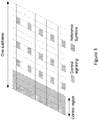
- ZP CSI-RS configurations They should have a periodicity which is a multiple of 5ms. Therefore, it is not possible to have one CSI-IM resource covering both of the CSI measurement sets, since the interval between the two types of subframes is not an integer multiple of 5ms as shown in Figure 4 .
- the first measurement set "CSI set 0" has been configured to cover the static downlink subframes
- the second measurement set "CSI set 1" covers the flexible subframes.
- subframe 0 a static downlink subframe in CSI set 0
- the distance to the subframes in CSI set 1 is either 3, 4, 8, or 9, none of which is a multiple of 5. The same applies for all the other subframes in CSI set 0.
- the UE is configured with two CSI processes and reports multiple CSI reflecting different channel and interference conditions in the two types of subframes.
- the downlink transmit power could be different between the two types of subframes if downlink transmit power control is applied. This can well be captured by the parameter Pc that is associated with each CSI process. Therefore, the channel part can be measured based on one common NZP CSI-RS resource configured in the static DL subframes.
- one possibility is to configure two CSI-IM resources in the two types of subframes so that different interference levels can be measured.
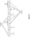
- the CSI-IM resource configurations namely that a UE is not expected to receive CSI-IM resource configuration(s) that are not all completely overlapping with one zero-power CSI-RS resource configuration which can be configured for the UE.
- all CSI-IM resources for the UE must be configured in a way such that they fall on a k ⁇ 5 ms time grid, where k is an integer and the smallest value of k is 1.
- a first CSI-IM resource configuration "CSI-IM 0" covers static downlink subframes 0 and 5 (which are 5 subframes apart) and a second CSI-IM resource configuration “CSI-IM 1" covers flexible subframes 3 and 8 (also 5 subframes apart).
- configuration "CSI-IM 1" might have been configured to cover flexible subframes 4 and 8 (indicated by the dashed lines).
- neither of these configurations would be allowable, because the subframes in CSI-IM 0 and CSI-IM 1 do not lie on the same k ⁇ 5 ms time grid.
- CSI-IM resource configuration restrictions are that some terminals (e.g. release 11 terminals configured in transmission mode 1-9) can only be configured with one single zero-power CSI-RS configuration, and the periodicity of this configuration must be a multiple of 5 ms.
- CSI-IM resources would be configured without the restriction, it would not be possible to configure those terminals to be aware of all the resources where zero-power CSI-RS are transmitted. This could cause decoding problems for these terminals, if they were to be scheduled in the subframes where zero-power CSI-RS are transmitted, because a different PDSCH mapping is used in those subframes. More specifically, the PDSCH mapping avoids the resource elements corresponding to the set of CSI-RS configured for the terminal.
- some embodiments provide a UE capability indicator, by which the UE may indicate to the network whether or not the CSI-IM resource configuration restriction applies.
- a UE capability indicator is sent from the UE to the eNB to indicate whether there is a restriction of CSI-IM resource configuration, whenever the network sends a request for UE capability information.
- the UE capability indicator could be a new field in the Feature group indicators as shown in Table 2.
- the UE may set this field to 1 if the restriction of CSI-IM resource configuration does not apply for the UE.
- the reverse interpretation of the bit is also possible, i.e. the field may be set to 0 if the restriction does not apply, as long as the UE and eNB both agree on the interpretation of the field.
- a new information element e.g. CSI-IM-configuration-norestriction
- UE-EUTRA-Capability a new information element added in the current UE capability IE UE-EUTRA-Capability.
- the UE shall set this field to "supported” if the resource of CSI-IM resource configuration does not apply.
- the UE capability indicator could be used to jointly indicate two or more capabilities.
- the indicator could indicate whether the UE supports subframe set-dependent CSI measurements, which would in turn imply that CSI-IM resource configuration restrictions do not apply for the UE.
- a Rel-11 UE when a Rel-11 UE enters a Rel-12 (or beyond) network, including initial access and handover, the UE will report its release information in the IE accessStratumRelease and it will not report UE capabilities regarding to restriction of CSI-IM resource configurations. Then the Rel-12 eNB knows that restriction of CSI-IM resource configuration does apply for this UE.
- the UE when a Rel-12 (and beyond) UE enters a Rel-11 network (including initial access and handover), the UE will report its release information in the IE accessStratumRelease and its capability indicator regarding to CSI-IM configurations. But the Rel-11 eNB could not recognize the field regarding to CSI-IM configuration restriction and thus will configure CSI-IM resources assuming that it is a Rel-11 UE. In one variant, the eNB then configures CSI-IM resources with restrictions.
- the eNB handles a legacy UE (or, stated differently, a UE that is bound by configuration restrictions) by instructing it to not perform interference averaging.
- a legacy UE or, stated differently, a UE that is bound by configuration restrictions
- the UE will report measurements separately for each subframe, thereby enabling the eNB to derive interference information separately for different subframe types.
- a Rel-12 (and beyond) eNB shall configure CSI-IM resources for a Rel-12 (and beyond) UE upon receiving the UE capability indicator implying that the restriction of CSI-IM resource configuration does not apply:
- the network node may e.g. be an LTE eNodeB.
- the network node uses dynamic TDD transmission.
- the present method could be applicable also to other situations than dynamic TDD, e.g. CoMP.
- the network node receives 804 information from a wireless device indicating whether CSI-IM resource configuration restriction applies for that wireless device.
- the wireless device may e.g. be an LTE UE.
- this is preceded by the network node transmitting 802 a request to the wireless device to send the information (e.g. a request for transfer of UE capability information).
- the received information may, in one variant, comprise capability information for the wireless device, e.g. UE capability information.
- a special capability indicator may be received from the wireless device, which indicates whether there is a restriction of CSI-IM resource configuration for this wireless device.
- the indicator may e.g. be implemented as a new field in the Feature group indicators, or as a new information element, as previously described.
- the special indicator will not be present in the UE capability information, in which case the absence of this indicator provides the information to the network node that the CSI-IM configuration restriction applies.
- the network node then configures 806 CSI-IM resources for the wireless device based on the information.
- the network node configures CSI-IM resources depending on whether the restriction applies or not.
- the information may indicate whether the wireless device is restricted to receiving CSI-IM resource configurations that are all completely overlapping with one zero-power CSI-RS resource configuration which can be configured for the wireless device. Stated differently, the information may indicate whether the wireless device is restricted to receiving CSI-IM resource configurations wherein all CSI-IM resources fall on the same k ⁇ 5 ms time grid, where k is an integer greater than or equal to 1.
- the network node may configure CSI-IM resources so that separate interference measurements are obtained for static downlink subframes and for flexible downlink subframes. This may be performed in various different ways, as will be described further below.
- the network node configures several CSI-IM resources for one CSI process as described above.
- two CSI-IM resources may be configured.
- One CSI-IM resource configuration would overlap with a zero-power CSI-RS configuration which covers static downlink subframes, and the other CSI-IM resource configuration would overlap with another zero-power CSI-RS configuration which covers flexible downlink subframes.
- the CSI process may also be associated with two CSI subframe sets, where one subframe set covers static downlink subframes and the other CSI subframe set covers flexible downlink subframes.
- the network node configures one CSI-IM resource such that it overlaps with a combination of two or more zero-power CSI-RS resource configurations configured for the wireless device.
- one CSI-IM resource configuration may be associated with two or more zero-power CSI-RS resource configurations.
- one CSI-IM resource configuration is associated with two zero-power CSI-RS resource configurations, where one zero-power CSI-RS resource configuration covers downlink subframes, and the other zero-power CSI-RS resource configuration covers flexible subframes.
- the CSI process may be associated with two CSI subframe sets as described in the previous paragraph.
- the network node in one variant configures the wireless device in accordance with the restrictions. Hence, in this variant the network node will not be able to obtain separate interference measurements for downlink subframes and flexible subframes.
- the network node instructs 1004 the wireless device to not perform interference averaging, for example via an RRC message. When interference averaging is not performed, the network node will receive measurements per subframe, and hence it will be possible for the network node to obtain separate measurement results per subframe type.
- the network node After configuring the CSI-IM resources for the wireless device, the network node will receive 808 measurement reports for the CSI process(es) according to the configuration. In more detail, the network node will receive one report for each CSI process, where the report may comprise several measurements associated with this CSI process (although it would also be possible to receive several reports per CSI process). The measurement reports may then be utilized for performing scheduling and/or link adaptation.
- Figure 9 shows a corresponding method for performing CSI measurements, which may be executed in a wireless device, e.g. an LTE UE.
- the wireless device transmits 904 information to a network node, e.g. an LTE eNodeB, the information indicating whether CSI-IM resource configuration restriction applies for the wireless device.
- a network node e.g. an LTE eNodeB
- this is preceded by the wireless device receiving 902 a request from the network node to send the information (e.g. a request for transfer of UE capability information).
- the transmitted information may, in one variant, comprise capability information for the wireless device, e.g. UE capability information.
- a capability indicator may be received from the wireless device, which may be implemented in any of the ways described above. Further, as explained above, the presence or absence of this indicator may provide the indication whether CSI-IM configuration restriction applies.
- the wireless device then receives 906 a CSI-IM resource configuration from the network node. Also as exemplified above, the resource configuration will be dependent on whether the configuration restriction applies or not.
- the information may indicate whether the wireless device is restricted to receiving CSI-IM resource configurations that are all completely overlapping with one zero-power CSI-RS resource configuration which can be configured for the wireless device. Stated differently, the information may indicate whether the wireless device is restricted to receiving CSI-IM resource configurations wherein all CSI-IM resources fall on the same k ⁇ 5 ms time grid, where k is an integer greater than or equal to 1.
- the wireless device may receive one or more CSI-IM resource configurations so that separate interference measurements are obtained for static downlink subframes and for flexible downlink subframes. This may be performed in various different ways, as will be described further below.
- the wireless device receives several CSI-IM resource configurations for one CSI process as described above.
- two CSI-IM resource configurations may be received.
- One CSI-IM resource configuration would overlap with a zero-power CSI-RS configuration which covers static downlink subframes, and the other CSI-IM resource configuration would overlap with another zero-power CSI-RS configuration which covers flexible downlink subframes.
- the CSI process may also be associated with two CSI subframe sets, where one subframe set covers static downlink subframes and the other CSI subframe set covers flexible downlink subframes.
- the wireless device receives one CSI-IM resource configuration such that it overlaps with a combination of two or more zero-power CSI-RS resource configurations configured for the wireless device.
- one CSI-IM resource configuration may be associated with two or more zero-power CSI-RS resource configurations.
- one CSI-IM resource configuration is associated with two zero-power CSI-RS resource configurations, where one zero-power CSI-RS resource configuration covers downlink subframes, and the other zero-power CSI-RS resource configuration covers flexible subframes.
- the CSI process may be associated with two CSI subframe sets as described in the previous paragraph.
- the wireless device then performs 908 measurements in accordance with the received configuration, and transmits one or more CSI reports for the CSI process to the network node.
- the network node may e.g. be an LTE eNodeB.
- the network node uses dynamic TDD.
- the network node receives 1002 information from a wireless device indicating that CSI-IM resource configuration restriction applies for that wireless device.
- the wireless device may e.g. be an LTE UE.
- this is preceded by the network node transmitting a request to the wireless device to send the information (e.g. a request for transfer of UE capability information).
- the received information may, in one variant, comprise UE capability information.
- a special capability indicator may be received from the wireless device, which indicates whether there is a restriction of CSI-IM resource configuration for this wireless device.
- the indicator may e.g. be implemented as a new field in the Feature group indicators, or as a new information element, as previously described.
- the special indicator will not be present in the UE capability information, in which case the absence of this indicator provides the information to the network node that the CSI-IM configuration restriction applies.
- the network node then configures 1006 CSI-IM resources for the wireless device with restrictions. Furthermore, the network node instructs 1004 the wireless device to not perform interference averaging. It should be noted that steps 1006 and 1004 may be performed in any order.
- the network node will then receive 1008 measurement reports for the CSI process(es) according to the configuration (in more detail, the network node will receive one report for each CSI process, where the report may comprise several measurements associated with this CSI process). As interference averaging is not performed, the network node will receive separate measurements per subframe, and hence it will be possible for the network node to obtain measurement results per subframe type. This embodiment may advantageously be applied when the network node uses dynamic TDD, and the wireless device is also configured for dynamic TDD transmission.
- the network node may configure the CSI-IM resources to cover two or more of the flexible subframes.
- Different flexible subframes may be subject to differing interference conditions, as the transmission direction of these subframes may be configured in different ways. For example, if a certain flexible subframe is configured as a downlink subframe in the serving cell as well as in neighboring cells, the level of interference in that subframe is likely to be similar to the interference level in the static downlink subframes. Therefore, obtaining separate measurements per subframe may provide the network node with a good picture of the different interference levels.
- the measurement reports may then be utilized for performing scheduling and/or link adaptation.
- Figure 11 shows a method in a wireless device, e.g. an LTE UE, which corresponds to the method of Figure 10 .
- the wireless device transmits 1102 information from a wireless device indicating that CSI-IM resource configuration restriction applies.
- the wireless device receives an instruction 1104 to not perform interference averaging.
- the wireless device performs 1106 measurements without doing interference averaging, and transmits measurement reports to the network node.
- measurements will be reported separately per subframe.
- the network node 1200 could be configured to be operable e.g.
- the network node 1200 is an LTE eNB.
- the network node 1200 is configured to communicate with other entities, in particular with wireless devices (such as LTE user equipments) via a transmitter/receiver.
- the network node 1200 further comprises a processor 1202 and a memory 1204, and the memory 1204 contains instructions executable by the processor 1202, whereby the network node 1200 is operable to perform a method for configuring CSI measurements as described above (e.g. the method shown in Figure 8 or Figure 10 ).
- the network node (1200) is operable to receive, from the wireless device, information indicating whether a channel state information interference measurement, CSI-IM, resource configuration restriction applies for the wireless device, and further operable to configure CSI-IM resources for the wireless device based on the information.
- the network node 1200 may further comprise other functional units, and may further comprise one or more storage units.
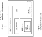
- the wireless device 1300 could be configured to be operable e.g. in an LTE and/or WCDMA system or in a multi-RAT system.
- the wireless device 1300 is an LTE UE.
- the wireless device 1300 is configured to communicate with other entities via a transmitter/receiver.
- the wireless device 1300 further comprises a processor 1302 and a memory 1304, and the memory 1304 contains instructions executable by the processor 1302, whereby the wireless device 1300 is operable to perform a method for performing CSI measurements as described above (e.g. the method shown in Figure 9 or Figure 11 ).
- the wireless device 1300 is operable to transmit, to a network node 1200, information indicating whether a CSI-IM resource configuration restriction applies for the wireless device 1300, to receive, from the network node 1200, one or more CSI-IM resource configurations, wherein the configurations are dependent on whether the CSI-IM resource configuration restriction applies for the wireless device 1300, and to perform measurements in accordance with the received one or more configurations, and transmit one or more CSI reports comprising the measurements to the network node 1200.
- the wireless device 1300 may further comprise other functional units, and may further comprise one or more storage units.
- Yet further embodiments provide a computer program product for execution by a wireless device arranged to perform channel state information measurements, the computer program product comprising program instructions for transmitting, to a network node, information indicating whether a CSI-IM resource configuration restriction applies for the wireless device, for receiving, from the network node, one or more CSI-IM resource configurations, wherein the configurations are dependent on whether the CSI-IM resource configuration restriction applies for the wireless device, and for performing measurements in accordance with the received one or more configurations, and transmitting one or more CSI reports comprising the measurements to the network node.
- wireless device encompasses any type of wireless node which is able to communicate with a network node, such as a base station, or with another wireless device by transmitting and/or receiving wireless signals.
- a network node such as a base station
- wireless device encompasses, but is not limited to: a user equipment, a mobile terminal, a stationary or mobile wireless device for machine-to-machine communication, an integrated or embedded wireless card, an externally plugged in wireless card, a dongle etc.
- the wireless device may also be a network node, e.g. a base station.
Landscapes
- Engineering & Computer Science (AREA)
- Signal Processing (AREA)
- Computer Networks & Wireless Communication (AREA)
- Quality & Reliability (AREA)
- Databases & Information Systems (AREA)
- Mobile Radio Communication Systems (AREA)
Priority Applications (1)
| Application Number | Priority Date | Filing Date | Title |
|---|---|---|---|
| PL14838341T PL3117545T3 (pl) | 2013-08-21 | 2014-08-21 | Sposób i układ do konfigurowania pomiarów CSI |
Applications Claiming Priority (2)
| Application Number | Priority Date | Filing Date | Title |
|---|---|---|---|
| CN2013081923 | 2013-08-21 | ||
| PCT/CN2014/084884 WO2015024519A1 (en) | 2013-08-21 | 2014-08-21 | Method and arrangement for configuring csi measurements |
Publications (3)
| Publication Number | Publication Date |
|---|---|
| EP3117545A1 EP3117545A1 (en) | 2017-01-18 |
| EP3117545A4 EP3117545A4 (en) | 2018-01-10 |
| EP3117545B1 true EP3117545B1 (en) | 2020-02-19 |
Family
ID=52483088
Family Applications (1)
| Application Number | Title | Priority Date | Filing Date |
|---|---|---|---|
| EP14838341.7A Active EP3117545B1 (en) | 2013-08-21 | 2014-08-21 | Method and arrangement for configuring csi measurements |
Country Status (7)
| Country | Link |
|---|---|
| US (2) | US9807763B2 (es) |
| EP (1) | EP3117545B1 (es) |
| CN (1) | CN105723640B (es) |
| ES (1) | ES2784228T3 (es) |
| MX (1) | MX358049B (es) |
| PL (1) | PL3117545T3 (es) |
| WO (1) | WO2015024519A1 (es) |
Families Citing this family (19)
| Publication number | Priority date | Publication date | Assignee | Title |
|---|---|---|---|---|
| EP3117545B1 (en) * | 2013-08-21 | 2020-02-19 | Telefonaktiebolaget LM Ericsson (publ) | Method and arrangement for configuring csi measurements |
| WO2016036097A1 (ko) * | 2014-09-01 | 2016-03-10 | 엘지전자 주식회사 | 비면허대역을 지원하는 무선접속시스템에서 채널상태측정 및 보고 방법 |
| CN107210801B (zh) * | 2015-02-05 | 2021-07-02 | Lg 电子株式会社 | 无线通信系统中执行干扰测量的方法及其装置 |
| CN106160825B (zh) * | 2015-04-20 | 2021-07-30 | 中兴通讯股份有限公司 | 信道信息的配置方法及装置、反馈方法及装置 |
| US10931342B2 (en) * | 2015-08-13 | 2021-02-23 | Samsung Electronics Co., Ltd. | Reference signal measurement method and apparatus for use in mobile communication system |
| WO2017034270A1 (ko) * | 2015-08-21 | 2017-03-02 | 엘지전자(주) | 무선 통신 시스템에서 채널 상태 정보 송수신 방법 및 이를 위한 장치 |
| US10200168B2 (en) * | 2015-08-27 | 2019-02-05 | Futurewei Technologies, Inc. | Systems and methods for adaptation in a wireless network |
| CN107872829B (zh) * | 2016-09-28 | 2021-08-20 | 华为技术有限公司 | 一种信号传输方法及相关设备 |
| US10263681B2 (en) * | 2016-10-10 | 2019-04-16 | Samsung Electronics Co., Ltd. | Method and apparatus for reporting periodic channel state information in mobile communication system using massive array antennas |
| WO2018070909A1 (en) | 2016-10-14 | 2018-04-19 | Telefonaktiebolaget Lm Ericsson (Publ) | Methods and apparatus for assignment of radio resources in a wireless network |
| WO2018084782A1 (en) * | 2016-11-04 | 2018-05-11 | Telefonaktiebolaget Lm Ericsson (Publ) | Systems and methods for handling non-typical interference in wireless communications networks |
| JP2020047961A (ja) * | 2017-01-06 | 2020-03-26 | 株式会社Nttドコモ | ユーザ装置及び基地局 |
| US11064401B2 (en) | 2017-04-01 | 2021-07-13 | Samsung Electronics Co., Ltd. | Random access method, network node and user equipment |
| CN109600841B (zh) * | 2017-09-30 | 2024-03-15 | 北京三星通信技术研究有限公司 | 随机接入方法、网络节点和用户设备 |
| US11228356B2 (en) | 2018-09-12 | 2022-01-18 | Telefonaktiebolaget Lm Ericsson (Publ) | Configuration of resources for downlink CSI measurements |
| CN110971339B (zh) * | 2018-09-28 | 2021-04-27 | 维沃移动通信有限公司 | 一种信息传输方法及终端 |
| CN112583462A (zh) * | 2019-09-27 | 2021-03-30 | 苹果公司 | 用于报告信号质量信息的系统和方法 |
| EP3799329A1 (en) | 2019-09-27 | 2021-03-31 | Apple Inc. | System and method for reporting signal quality information |
| US11632157B2 (en) * | 2020-02-13 | 2023-04-18 | Samsung Electronics Co., Ltd. | Method and apparatus for interference measurement |
Family Cites Families (31)
| Publication number | Priority date | Publication date | Assignee | Title |
|---|---|---|---|---|
| CN101635932B (zh) * | 2008-07-21 | 2012-08-29 | 华为技术有限公司 | 信道检测和上报方法及系统、终端、管理中心 |
| CN101877608B (zh) | 2010-06-30 | 2015-07-22 | 中兴通讯股份有限公司 | 一种针对协作波束赋型的优化加权csi反馈方法和装置 |
| CN102082636B (zh) * | 2010-08-16 | 2013-05-08 | 电信科学技术研究院 | 一种信道状态信息csi反馈指示方法和基站及系统 |
| KR20120049449A (ko) * | 2010-11-08 | 2012-05-17 | 삼성전자주식회사 | 무선 통신 시스템 및 그 시스템에서 간섭 조정을 위한 자원 관리 방법 |
| CN107318125B (zh) * | 2010-11-11 | 2021-08-27 | 瑞典爱立信有限公司 | 用于配置abs传输模式以及对应测量模式的方法和网络节点 |
| US9253791B2 (en) | 2011-12-09 | 2016-02-02 | Lg Electronics Inc. | Method and apparatus of reference signal dropping |
| US9008585B2 (en) * | 2012-01-30 | 2015-04-14 | Futurewei Technologies, Inc. | System and method for wireless communications measurements and CSI feedback |
| US9155098B2 (en) * | 2012-03-29 | 2015-10-06 | Qualcomm Incorporated | Channel state information reference signal (CSI-RS) configuration and CSI reporting restrictions |
| CN103516464B (zh) * | 2012-06-20 | 2018-04-10 | 中兴通讯股份有限公司 | 信道状态信息报告的反馈方法及装置 |
| WO2014007512A1 (ko) * | 2012-07-02 | 2014-01-09 | 엘지전자 주식회사 | 무선 통신 시스템에서 채널상태정보 보고 방법 및 장치 |
| CN103580820A (zh) * | 2012-08-03 | 2014-02-12 | 上海贝尔股份有限公司 | 控制ri报告的方法及装置 |
| US8983002B2 (en) * | 2012-10-02 | 2015-03-17 | Broadcom Corporation | Systems and methods for establishing transmission format parameters between communication devices |
| US11139862B2 (en) * | 2012-11-02 | 2021-10-05 | Samsung Electronics Co., Ltd. | Configuration of rate matching and interference measurement resources for coordinated multi-point transmission |
| US9407302B2 (en) * | 2012-12-03 | 2016-08-02 | Intel Corporation | Communication device, mobile terminal, method for requesting information and method for providing information |
| EP2939485B1 (en) * | 2012-12-27 | 2018-08-15 | Telefonaktiebolaget LM Ericsson (publ) | Method and apparatus for measurement procedures with composite dynamic subframes in dynamic tdd |
| US10020859B2 (en) * | 2013-01-17 | 2018-07-10 | Nec Corporation | Channel feedback for vertical and full-dimensional beamforming |
| US9300451B2 (en) * | 2013-03-13 | 2016-03-29 | Samsung Electronics Co., Ltd. | Transmission of sounding reference signals for adaptively configured TDD communication systems |
| US9306725B2 (en) * | 2013-03-13 | 2016-04-05 | Samsung Electronics Co., Ltd. | Channel state information for adaptively configured TDD communication systems |
| WO2014157940A1 (ko) * | 2013-03-27 | 2014-10-02 | 엘지전자 주식회사 | 다증 샐 기반 무선 통신 시스템에서 참조 신호를 설정하는 방법 및 이를 위한 장치 |
| CN105122680B (zh) * | 2013-04-16 | 2019-01-29 | Lg 电子株式会社 | 在无线通信系统中报告信道状态信息的方法和设备 |
| US9680522B2 (en) * | 2013-05-09 | 2017-06-13 | Texas Instruments Incorporated | Dynamic reconfiguration of uplink transmission in a TDD wireless communication system |
| EP3117545B1 (en) * | 2013-08-21 | 2020-02-19 | Telefonaktiebolaget LM Ericsson (publ) | Method and arrangement for configuring csi measurements |
| KR20160075503A (ko) * | 2013-10-21 | 2016-06-29 | 엘지전자 주식회사 | 무선 통신 시스템에서 간섭 측정 자원 설정 방법 및 이를 위한 장치 |
| US9819471B2 (en) * | 2013-11-04 | 2017-11-14 | Texas Instruments Incorporated | Method and apparatus for configuration, measurement and reporting of channel state information for LTE TDD with dynamic UL/DL configuration |
| WO2015126080A1 (ko) * | 2014-02-18 | 2015-08-27 | 엘지전자 주식회사 | 무선 통신 시스템에서 단말이 채널 상태 정보를 보고하는 방법 및 이를 위한 장치 |
| US10003448B2 (en) * | 2014-02-18 | 2018-06-19 | Lg Electronics Inc. | Method for reporting channel status information in wireless communication system supporting change in use of wireless resources, and device therefor |
| CN104935389B (zh) * | 2014-03-21 | 2020-05-19 | 中兴通讯股份有限公司 | 信道状态信息测量方法和装置 |
| US10419174B2 (en) * | 2014-03-30 | 2019-09-17 | Lg Electronics Inc. | Method for configuring an interference measurement resource in a wireless communication system, and apparatus for thereof |
| US9813216B2 (en) * | 2014-04-04 | 2017-11-07 | Lg Electronics Inc. | Method for reporting channel state information having interference cancellation capability reflected therein, and apparatus therefor |
| KR102354498B1 (ko) * | 2014-04-16 | 2022-01-21 | 엘지전자 주식회사 | 무선 통신 시스템에서 비주기적 채널 상태 정보를 처리하는 방법 및 장치 |
| WO2016024731A1 (ko) * | 2014-08-12 | 2016-02-18 | 엘지전자 주식회사 | 무선 통신 시스템에서 채널 상태 보고를 위한 방법 및 이를 위한 장치 |
-
2014
- 2014-08-21 EP EP14838341.7A patent/EP3117545B1/en active Active
- 2014-08-21 US US14/442,431 patent/US9807763B2/en active Active
- 2014-08-21 WO PCT/CN2014/084884 patent/WO2015024519A1/en active Application Filing
- 2014-08-21 MX MX2016002148A patent/MX358049B/es active IP Right Grant
- 2014-08-21 CN CN201480057869.8A patent/CN105723640B/zh active Active
- 2014-08-21 ES ES14838341T patent/ES2784228T3/es active Active
- 2014-08-21 PL PL14838341T patent/PL3117545T3/pl unknown
-
2017
- 2017-09-26 US US15/716,053 patent/US10397917B2/en active Active
Non-Patent Citations (1)
| Title |
|---|
| None * |
Also Published As
| Publication number | Publication date |
|---|---|
| US10397917B2 (en) | 2019-08-27 |
| MX2016002148A (es) | 2017-03-01 |
| US20160278077A1 (en) | 2016-09-22 |
| PL3117545T3 (pl) | 2020-07-27 |
| WO2015024519A1 (en) | 2015-02-26 |
| MX358049B (es) | 2018-08-03 |
| EP3117545A4 (en) | 2018-01-10 |
| EP3117545A1 (en) | 2017-01-18 |
| CN105723640A (zh) | 2016-06-29 |
| US20180092088A1 (en) | 2018-03-29 |
| ES2784228T3 (es) | 2020-09-23 |
| US9807763B2 (en) | 2017-10-31 |
| CN105723640B (zh) | 2020-03-03 |
Similar Documents
| Publication | Publication Date | Title |
|---|---|---|
| US10397917B2 (en) | Method and arrangement for configuring CSI measurements | |
| US11825484B2 (en) | Control channel and data channel transmission/reception method and apparatus for NR system | |
| EP3528569B1 (en) | Techniques for uplink sounding reference signal transmission and reception | |
| CN110870245B (zh) | 用于物理信道的取决于帧结构的配置的方法和装置 | |
| JP6878278B2 (ja) | 端末、無線通信方法、基地局及びシステム | |
| JP6310087B2 (ja) | ユーザ端末及び無線通信方法 | |
| CN110958101B (zh) | 用户终端、无线基站以及无线通信方法 | |
| EP3169005B1 (en) | Method for reporting channel state information on unlicensed band in wireless communication system and apparatus for same | |
| EP2944147B1 (en) | Simultaneous uplink transmissions in dual connectivity mode | |
| EP2995113B1 (en) | Measurements in a wireless system | |
| US20170280479A1 (en) | Radio access node, communication terminal and methods performed therein | |
| WO2017130991A1 (ja) | ユーザ端末、無線基地局及び無線通信方法 | |
| JP6698519B2 (ja) | 無線基地局、ユーザ端末及び無線通信方法 | |
| EP3879906B1 (en) | User terminal, radio base station and radio communication method | |
| WO2017130990A1 (ja) | ユーザ端末、無線基地局及び無線通信方法 | |
| JP5781016B2 (ja) | 無線基地局、無線通信システム及び無線通信方法 | |
| JP6743288B2 (ja) | 無線通信システムにおける短い送信時間間隔を支援する端末のための上りリンク信号送信又は受信方法及びそのための装置 | |
| WO2015042870A1 (en) | Csi reporting for lte-tdd eimta | |
| CN107211420B (zh) | 用户终端、无线基站、无线通信系统以及无线通信方法 | |
| EP3416426A1 (en) | Method for transmitting information about transmission modes, network device, terminal device, and system | |
| WO2014119865A1 (ko) | 무선 통신 시스템에서 하향링크 제어 신호를 수신 또는 전송하기 위한 방법 및 이를 위한 장치 | |
| US20150124733A1 (en) | Method for controlling interference in wireless communication system and apparatus therefor | |
| EP3425977A1 (en) | User terminal, radio base station and radio communication method | |
| CN112314030A (zh) | 设备对设备(d2d)通信管理技术 |
Legal Events
| Date | Code | Title | Description |
|---|---|---|---|
| PUAI | Public reference made under article 153(3) epc to a published international application that has entered the european phase |
Free format text: ORIGINAL CODE: 0009012 |
|
| STAA | Information on the status of an ep patent application or granted ep patent |
Free format text: STATUS: REQUEST FOR EXAMINATION WAS MADE |
|
| 17P | Request for examination filed |
Effective date: 20160314 |
|
| AK | Designated contracting states |
Kind code of ref document: A1 Designated state(s): AL AT BE BG CH CY CZ DE DK EE ES FI FR GB GR HR HU IE IS IT LI LT LU LV MC MK MT NL NO PL PT RO RS SE SI SK SM TR |
|
| A4 | Supplementary search report drawn up and despatched |
Effective date: 20171213 |
|
| RIC1 | Information provided on ipc code assigned before grant |
Ipc: H04L 1/00 20060101AFI20171207BHEP |
|
| GRAP | Despatch of communication of intention to grant a patent |
Free format text: ORIGINAL CODE: EPIDOSNIGR1 |
|
| STAA | Information on the status of an ep patent application or granted ep patent |
Free format text: STATUS: GRANT OF PATENT IS INTENDED |
|
| INTG | Intention to grant announced |
Effective date: 20190924 |
|
| GRAS | Grant fee paid |
Free format text: ORIGINAL CODE: EPIDOSNIGR3 |
|
| GRAA | (expected) grant |
Free format text: ORIGINAL CODE: 0009210 |
|
| STAA | Information on the status of an ep patent application or granted ep patent |
Free format text: STATUS: THE PATENT HAS BEEN GRANTED |
|
| AK | Designated contracting states |
Kind code of ref document: B1 Designated state(s): AL AT BE BG CH CY CZ DE DK EE ES FI FR GB GR HR HU IE IS IT LI LT LU LV MC MK MT NL NO PL PT RO RS SE SI SK SM TR |
|
| REG | Reference to a national code |
Ref country code: CH Ref legal event code: EP |
|
| REG | Reference to a national code |
Ref country code: DE Ref legal event code: R096 Ref document number: 602014061319 Country of ref document: DE |
|
| REG | Reference to a national code |
Ref country code: AT Ref legal event code: REF Ref document number: 1236173 Country of ref document: AT Kind code of ref document: T Effective date: 20200315 |
|
| REG | Reference to a national code |
Ref country code: IE Ref legal event code: FG4D |
|
| REG | Reference to a national code |
Ref country code: NL Ref legal event code: FP |
|
| REG | Reference to a national code |
Ref country code: GR Ref legal event code: EP Ref document number: 20200400969 Country of ref document: GR Effective date: 20200615 |
|
| PG25 | Lapsed in a contracting state [announced via postgrant information from national office to epo] |
Ref country code: FI Free format text: LAPSE BECAUSE OF FAILURE TO SUBMIT A TRANSLATION OF THE DESCRIPTION OR TO PAY THE FEE WITHIN THE PRESCRIBED TIME-LIMIT Effective date: 20200219 Ref country code: NO Free format text: LAPSE BECAUSE OF FAILURE TO SUBMIT A TRANSLATION OF THE DESCRIPTION OR TO PAY THE FEE WITHIN THE PRESCRIBED TIME-LIMIT Effective date: 20200519 Ref country code: RS Free format text: LAPSE BECAUSE OF FAILURE TO SUBMIT A TRANSLATION OF THE DESCRIPTION OR TO PAY THE FEE WITHIN THE PRESCRIBED TIME-LIMIT Effective date: 20200219 |
|
| REG | Reference to a national code |
Ref country code: LT Ref legal event code: MG4D |
|
| PG25 | Lapsed in a contracting state [announced via postgrant information from national office to epo] |
Ref country code: SE Free format text: LAPSE BECAUSE OF FAILURE TO SUBMIT A TRANSLATION OF THE DESCRIPTION OR TO PAY THE FEE WITHIN THE PRESCRIBED TIME-LIMIT Effective date: 20200219 Ref country code: IS Free format text: LAPSE BECAUSE OF FAILURE TO SUBMIT A TRANSLATION OF THE DESCRIPTION OR TO PAY THE FEE WITHIN THE PRESCRIBED TIME-LIMIT Effective date: 20200619 Ref country code: HR Free format text: LAPSE BECAUSE OF FAILURE TO SUBMIT A TRANSLATION OF THE DESCRIPTION OR TO PAY THE FEE WITHIN THE PRESCRIBED TIME-LIMIT Effective date: 20200219 Ref country code: LV Free format text: LAPSE BECAUSE OF FAILURE TO SUBMIT A TRANSLATION OF THE DESCRIPTION OR TO PAY THE FEE WITHIN THE PRESCRIBED TIME-LIMIT Effective date: 20200219 Ref country code: BG Free format text: LAPSE BECAUSE OF FAILURE TO SUBMIT A TRANSLATION OF THE DESCRIPTION OR TO PAY THE FEE WITHIN THE PRESCRIBED TIME-LIMIT Effective date: 20200519 |
|
| REG | Reference to a national code |
Ref country code: ES Ref legal event code: FG2A Ref document number: 2784228 Country of ref document: ES Kind code of ref document: T3 Effective date: 20200923 |
|
| PG25 | Lapsed in a contracting state [announced via postgrant information from national office to epo] |
Ref country code: LT Free format text: LAPSE BECAUSE OF FAILURE TO SUBMIT A TRANSLATION OF THE DESCRIPTION OR TO PAY THE FEE WITHIN THE PRESCRIBED TIME-LIMIT Effective date: 20200219 Ref country code: RO Free format text: LAPSE BECAUSE OF FAILURE TO SUBMIT A TRANSLATION OF THE DESCRIPTION OR TO PAY THE FEE WITHIN THE PRESCRIBED TIME-LIMIT Effective date: 20200219 Ref country code: SK Free format text: LAPSE BECAUSE OF FAILURE TO SUBMIT A TRANSLATION OF THE DESCRIPTION OR TO PAY THE FEE WITHIN THE PRESCRIBED TIME-LIMIT Effective date: 20200219 Ref country code: PT Free format text: LAPSE BECAUSE OF FAILURE TO SUBMIT A TRANSLATION OF THE DESCRIPTION OR TO PAY THE FEE WITHIN THE PRESCRIBED TIME-LIMIT Effective date: 20200712 Ref country code: EE Free format text: LAPSE BECAUSE OF FAILURE TO SUBMIT A TRANSLATION OF THE DESCRIPTION OR TO PAY THE FEE WITHIN THE PRESCRIBED TIME-LIMIT Effective date: 20200219 Ref country code: SM Free format text: LAPSE BECAUSE OF FAILURE TO SUBMIT A TRANSLATION OF THE DESCRIPTION OR TO PAY THE FEE WITHIN THE PRESCRIBED TIME-LIMIT Effective date: 20200219 Ref country code: DK Free format text: LAPSE BECAUSE OF FAILURE TO SUBMIT A TRANSLATION OF THE DESCRIPTION OR TO PAY THE FEE WITHIN THE PRESCRIBED TIME-LIMIT Effective date: 20200219 |
|
| REG | Reference to a national code |
Ref country code: AT Ref legal event code: MK05 Ref document number: 1236173 Country of ref document: AT Kind code of ref document: T Effective date: 20200219 |
|
| REG | Reference to a national code |
Ref country code: DE Ref legal event code: R097 Ref document number: 602014061319 Country of ref document: DE |
|
| PLBE | No opposition filed within time limit |
Free format text: ORIGINAL CODE: 0009261 |
|
| STAA | Information on the status of an ep patent application or granted ep patent |
Free format text: STATUS: NO OPPOSITION FILED WITHIN TIME LIMIT |
|
| 26N | No opposition filed |
Effective date: 20201120 |
|
| PG25 | Lapsed in a contracting state [announced via postgrant information from national office to epo] |
Ref country code: AT Free format text: LAPSE BECAUSE OF FAILURE TO SUBMIT A TRANSLATION OF THE DESCRIPTION OR TO PAY THE FEE WITHIN THE PRESCRIBED TIME-LIMIT Effective date: 20200219 |
|
| PG25 | Lapsed in a contracting state [announced via postgrant information from national office to epo] |
Ref country code: SI Free format text: LAPSE BECAUSE OF FAILURE TO SUBMIT A TRANSLATION OF THE DESCRIPTION OR TO PAY THE FEE WITHIN THE PRESCRIBED TIME-LIMIT Effective date: 20200219 |
|
| PG25 | Lapsed in a contracting state [announced via postgrant information from national office to epo] |
Ref country code: MC Free format text: LAPSE BECAUSE OF FAILURE TO SUBMIT A TRANSLATION OF THE DESCRIPTION OR TO PAY THE FEE WITHIN THE PRESCRIBED TIME-LIMIT Effective date: 20200219 |
|
| PG25 | Lapsed in a contracting state [announced via postgrant information from national office to epo] |
Ref country code: LU Free format text: LAPSE BECAUSE OF NON-PAYMENT OF DUE FEES Effective date: 20200821 |
|
| PG25 | Lapsed in a contracting state [announced via postgrant information from national office to epo] |
Ref country code: MT Free format text: LAPSE BECAUSE OF FAILURE TO SUBMIT A TRANSLATION OF THE DESCRIPTION OR TO PAY THE FEE WITHIN THE PRESCRIBED TIME-LIMIT Effective date: 20200219 Ref country code: CY Free format text: LAPSE BECAUSE OF FAILURE TO SUBMIT A TRANSLATION OF THE DESCRIPTION OR TO PAY THE FEE WITHIN THE PRESCRIBED TIME-LIMIT Effective date: 20200219 |
|
| PG25 | Lapsed in a contracting state [announced via postgrant information from national office to epo] |
Ref country code: MK Free format text: LAPSE BECAUSE OF FAILURE TO SUBMIT A TRANSLATION OF THE DESCRIPTION OR TO PAY THE FEE WITHIN THE PRESCRIBED TIME-LIMIT Effective date: 20200219 Ref country code: AL Free format text: LAPSE BECAUSE OF FAILURE TO SUBMIT A TRANSLATION OF THE DESCRIPTION OR TO PAY THE FEE WITHIN THE PRESCRIBED TIME-LIMIT Effective date: 20200219 |
|
| PGFP | Annual fee paid to national office [announced via postgrant information from national office to epo] |
Ref country code: NL Payment date: 20230826 Year of fee payment: 10 |
|
| PGFP | Annual fee paid to national office [announced via postgrant information from national office to epo] |
Ref country code: TR Payment date: 20230808 Year of fee payment: 10 Ref country code: IT Payment date: 20230822 Year of fee payment: 10 Ref country code: IE Payment date: 20230828 Year of fee payment: 10 Ref country code: GB Payment date: 20230828 Year of fee payment: 10 Ref country code: ES Payment date: 20230901 Year of fee payment: 10 Ref country code: CZ Payment date: 20230810 Year of fee payment: 10 Ref country code: CH Payment date: 20230903 Year of fee payment: 10 |
|
| PGFP | Annual fee paid to national office [announced via postgrant information from national office to epo] |
Ref country code: PL Payment date: 20230808 Year of fee payment: 10 Ref country code: GR Payment date: 20230829 Year of fee payment: 10 Ref country code: FR Payment date: 20230825 Year of fee payment: 10 Ref country code: DE Payment date: 20230829 Year of fee payment: 10 Ref country code: BE Payment date: 20230828 Year of fee payment: 10 |