EP3117258B1 - Insert de microscope - Google Patents
Insert de microscope Download PDFInfo
- Publication number
- EP3117258B1 EP3117258B1 EP15760909.0A EP15760909A EP3117258B1 EP 3117258 B1 EP3117258 B1 EP 3117258B1 EP 15760909 A EP15760909 A EP 15760909A EP 3117258 B1 EP3117258 B1 EP 3117258B1
- Authority
- EP
- European Patent Office
- Prior art keywords
- light
- microscope
- insert
- beam splitter
- display device
- Prior art date
- Legal status (The legal status is an assumption and is not a legal conclusion. Google has not performed a legal analysis and makes no representation as to the accuracy of the status listed.)
- Not-in-force
Links
Images


Classifications
-
- G—PHYSICS
- G02—OPTICS
- G02B—OPTICAL ELEMENTS, SYSTEMS OR APPARATUS
- G02B21/00—Microscopes
- G02B21/36—Microscopes arranged for photographic purposes or projection purposes or digital imaging or video purposes including associated control and data processing arrangements
- G02B21/365—Control or image processing arrangements for digital or video microscopes
-
- G—PHYSICS
- G02—OPTICS
- G02B—OPTICAL ELEMENTS, SYSTEMS OR APPARATUS
- G02B21/00—Microscopes
- G02B21/18—Arrangements with more than one light path, e.g. for comparing two specimens
- G02B21/20—Binocular arrangements
- G02B21/22—Stereoscopic arrangements
-
- A—HUMAN NECESSITIES
- A61—MEDICAL OR VETERINARY SCIENCE; HYGIENE
- A61B—DIAGNOSIS; SURGERY; IDENTIFICATION
- A61B3/00—Apparatus for testing the eyes; Instruments for examining the eyes
- A61B3/0016—Operational features thereof
- A61B3/0025—Operational features thereof characterised by electronic signal processing, e.g. eye models
-
- A—HUMAN NECESSITIES
- A61—MEDICAL OR VETERINARY SCIENCE; HYGIENE
- A61B—DIAGNOSIS; SURGERY; IDENTIFICATION
- A61B3/00—Apparatus for testing the eyes; Instruments for examining the eyes
- A61B3/0016—Operational features thereof
- A61B3/0041—Operational features thereof characterised by display arrangements
-
- A—HUMAN NECESSITIES
- A61—MEDICAL OR VETERINARY SCIENCE; HYGIENE
- A61B—DIAGNOSIS; SURGERY; IDENTIFICATION
- A61B3/00—Apparatus for testing the eyes; Instruments for examining the eyes
- A61B3/10—Objective types, i.e. instruments for examining the eyes independent of the patients' perceptions or reactions
- A61B3/13—Ophthalmic microscopes
-
- A—HUMAN NECESSITIES
- A61—MEDICAL OR VETERINARY SCIENCE; HYGIENE
- A61B—DIAGNOSIS; SURGERY; IDENTIFICATION
- A61B3/00—Apparatus for testing the eyes; Instruments for examining the eyes
- A61B3/10—Objective types, i.e. instruments for examining the eyes independent of the patients' perceptions or reactions
- A61B3/14—Arrangements specially adapted for eye photography
-
- G—PHYSICS
- G02—OPTICS
- G02B—OPTICAL ELEMENTS, SYSTEMS OR APPARATUS
- G02B21/00—Microscopes
- G02B21/0004—Microscopes specially adapted for specific applications
- G02B21/0012—Surgical microscopes
-
- G—PHYSICS
- G02—OPTICS
- G02B—OPTICAL ELEMENTS, SYSTEMS OR APPARATUS
- G02B21/00—Microscopes
- G02B21/18—Arrangements with more than one light path, e.g. for comparing two specimens
-
- G—PHYSICS
- G02—OPTICS
- G02B—OPTICAL ELEMENTS, SYSTEMS OR APPARATUS
- G02B21/00—Microscopes
- G02B21/36—Microscopes arranged for photographic purposes or projection purposes or digital imaging or video purposes including associated control and data processing arrangements
- G02B21/361—Optical details, e.g. image relay to the camera or image sensor
-
- G—PHYSICS
- G02—OPTICS
- G02B—OPTICAL ELEMENTS, SYSTEMS OR APPARATUS
- G02B21/00—Microscopes
- G02B21/36—Microscopes arranged for photographic purposes or projection purposes or digital imaging or video purposes including associated control and data processing arrangements
- G02B21/362—Mechanical details, e.g. mountings for the camera or image sensor, housings
-
- G—PHYSICS
- G02—OPTICS
- G02B—OPTICAL ELEMENTS, SYSTEMS OR APPARATUS
- G02B21/00—Microscopes
- G02B21/36—Microscopes arranged for photographic purposes or projection purposes or digital imaging or video purposes including associated control and data processing arrangements
- G02B21/368—Microscopes arranged for photographic purposes or projection purposes or digital imaging or video purposes including associated control and data processing arrangements details of associated display arrangements, e.g. mounting of LCD monitor
-
- G—PHYSICS
- G02—OPTICS
- G02B—OPTICAL ELEMENTS, SYSTEMS OR APPARATUS
- G02B27/00—Optical systems or apparatus not provided for by any of the groups G02B1/00 - G02B26/00, G02B30/00
- G02B27/01—Head-up displays
- G02B27/0101—Head-up displays characterised by optical features
-
- G—PHYSICS
- G02—OPTICS
- G02B—OPTICAL ELEMENTS, SYSTEMS OR APPARATUS
- G02B27/00—Optical systems or apparatus not provided for by any of the groups G02B1/00 - G02B26/00, G02B30/00
- G02B27/28—Optical systems or apparatus not provided for by any of the groups G02B1/00 - G02B26/00, G02B30/00 for polarising
- G02B27/283—Optical systems or apparatus not provided for by any of the groups G02B1/00 - G02B26/00, G02B30/00 for polarising used for beam splitting or combining
-
- G—PHYSICS
- G02—OPTICS
- G02B—OPTICAL ELEMENTS, SYSTEMS OR APPARATUS
- G02B27/00—Optical systems or apparatus not provided for by any of the groups G02B1/00 - G02B26/00, G02B30/00
- G02B27/28—Optical systems or apparatus not provided for by any of the groups G02B1/00 - G02B26/00, G02B30/00 for polarising
- G02B27/286—Optical systems or apparatus not provided for by any of the groups G02B1/00 - G02B26/00, G02B30/00 for polarising for controlling or changing the state of polarisation, e.g. transforming one polarisation state into another
-
- G—PHYSICS
- G02—OPTICS
- G02B—OPTICAL ELEMENTS, SYSTEMS OR APPARATUS
- G02B27/00—Optical systems or apparatus not provided for by any of the groups G02B1/00 - G02B26/00, G02B30/00
- G02B27/01—Head-up displays
- G02B27/0101—Head-up displays characterised by optical features
- G02B2027/0141—Head-up displays characterised by optical features characterised by the informative content of the display
Definitions
- This disclosure is related in general to surgical microscopes and in particular to a microscope insert for surgical microscopes.
- the present invention provides a microscope insert, comprising:
- a microscope insert includes a beam splitter configured to receive first light from an object.
- the beam splitter directs a first portion of the first light in a first direction to a viewing device and directs a second portion of the first light in a second direction.
- the microscope insert further includes a camera configured to receive the second portion of the first light from the beam splitter and to generate a first signal representing the object, and a processing unit configured to receive the first signal representing the object and determine characteristics of the object by analyzing the first signal.
- the processing unit further generates a second signal representing information relevant to the object.
- the microscope insert further includes a display device configured to receive the second signal from the processing unit and generate a graphical representation of the information based on the second signal and transmit second light corresponding to the graphical representation.
- the microscope insert further includes a polarizer element configured to modify a polarization of the second light from the display device.
- the beam splitter receives the modified second light from the polarizer element and directs a first portion of the modified second light in the first direction to the viewing device. The first portion of the modified second light and the first portion of the first light from the object are combined for simultaneous viewing of the graphical representation and the object by the user.
- a microscope insert includes a first channel, a second channel, and a processing unit.
- the first and second channels each include a beam splitter configured to receive first light from an object.
- the beam splitter directs a first portion of the first light in a first direction to a viewing device and directs a second portion of the first light to a second direction.
- the first and second channels each further include a camera configured to receive the second portion of the first light from the beam splitter and generate a first signal representing the object, a display device, and a polarizer element.
- the processing unit is configured to receive the first signal representing the object, determine characteristics of the object by analyzing the first signal, and generate a second signal representing information relevant to the object.
- the display device is configured to receive the second signal from the processing unit, generate a graphical representation of the information based on the second signal, and transmit second light representing the graphical representation.
- the polarizer element is configured to modify a polarization of the second light from the display device.
- the beam splitter receives the modified second light from the polarizer element and directs a first portion of the modified second light in the first direction, alone with the first portion of the first light from the object, to the viewing device for simultaneous viewing of the graphical representation and the object by the user.
- a method for generating an overlaid image in a microscope includes receiving first light from an object, directing a first portion of the first light in a first direction to a viewing device and a second portion of the first light in a second direction to a camera, generating, based on the second portion of the first iight, a graphical representation of information relevant to the object, projecting second light corresponding to the graphical representation, modifying a polarization of the second light, and directing at least a portion of the modified second light in the first direction so that the portion of the modified second light and the first portion of the first light are combined for simultaneously viewing of the object and the graphical representation by a user.
- a method for generating an overlaid image in a microscope includes receiving a first light from a microscope corresponding to a first image corresponding to an object, directing a first portion of the first light to a viewing device and a second portion of the first light to a camera, generating, based on the second portion of the first light, a second image to be overlaid on the first mage, projecting second light corresponding to the second image, directing a first portion of the second light to the camera and a second portion of the second light to the viewing device, and combining the first portion of the first light and the second portion of the second light to form a combined image.
- the combined image includes the first image corresponding to the object and the second image generated by the display device.
- the second image is rendered over the first image.
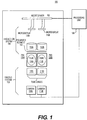
- a microscope insert 100 includes a projection system 104 and an imaging system 106.
- Projection system 104 includes one or more display devices 110A and 110B and one or more sets of tube lenses 112A and 112B for projecting images from the display devices 110A and 110B.
- Imaging system 106 includes one or more cameras 118A and 118B and one or more sets of tube lenses 112C and 112D for focusing images to cameras 118A and 118B.
- Microscope insert 100 further includes one or more polarizing beam splitters (PBS) 120A and 120B, which will be further described below,
- PBS polarizing beam splitters
- Each optical channel includes a display device 110A/110B, a camera 118A/118B, a polarizing beam splitter 120A/120B, and corresponding tube lenses 112A/112B and 112C/112D.
- a polarizer element 114 may be disposed between tube lenses 112A/112B and polarizing beam splitters 120A/120B.
- polarizer element 114 may include different pieces for respective optical channels.
- Figure 1 shows two optical channels for microscope insert 100
- insert 100 may have any number of optical channels, each having a structure similar to those depicted in Figure 1 .
- videos/images generated by the optical channels are configured so as to provide a user with stereoscopic rendering.
- cameras 118A and 118B are digital imaging devices, such as the Point Grey FL3-U3-13S2C-CS manufactured by Point Grey Research.
- a number of different cameras may be used, providing different features, such as a CMOS or CCD based sensor, a global or rolling shutter, and a range of resolutions at about 20 FPS or higher.
- display devices 110A and 110B may be LCOS (Liquid Crystal on Silicon) microdisplay devices, each of which has pixels that can be individually adjusted to match or exceed the brightness of the microscope.
- LCOS Liquid Crystal on Silicon
- Other display technologies may also be used, such as OLED, DLP, T-OLED, MEMS, and LCD-based displays.
- Insert 100 also includes a display driver circuit 102 to control display devices 110A and 1108 and/or other system elements or features.
- Display driver circuit 102 may generate video/image data that are suitable for rendering by display devices 110A and 110B.
- Insert 100 is connected to a processing unit 108 via standard communication protocols.
- Processing unit 108 may or may not be disposed within insert 100.
- Processing unit 108 receives video/image signals from cameras 118A and 118B and sends the video/image signals to driver circuit 102 for rendering the videos/images on display devices 110A and 110B.
- Processing unit 108 may apply additional processing on videos/images data received from cameras 118A and 118B.
- processing unit 108 may perform image processing techniques, such as image registration, pattern recognition, image filtering, image enhancement, and the like.
- Processing unit 108 may also be connected to other peripherals to collect data to be used by microscope insert 100, to generate visual guidance for navigation during a surgical procedure, or to provide alternative graphical user interfaces on external display devices to supplement the display through microscope insert 100.
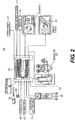
- FIG. 2 illustrates a surgical system 200 including a microscope insert 228 according to a further embodiment.
- Surgical system 200 includes a microscope 226 coupled to microscope insert 228.
- Microscope insert 228 generally corresponds to microscope insert 100 of Figure 1 .
- Insert 228 communicates with a processing unit 230, which corresponds to processing unit 108 of Figure 1 .
- Microscope 226 receives light or optical signals reflected from an object through its lens system and the polarized beam splitters (e.g., PBS's 120A and 120B), which pass the optical signals to the cameras (e.g., cameras 118A and 118B) of microscope insert 228.
- the cameras of microscope insert 228 convert the optical signals to digital data representing videos/images of the object and transmit the digital data to processing unit 230.
- Processing unit 230 performs image processing on the digital data and sends processed data and relevant commands to the driver circuit (e.g., driver circuit 102) of microscope 226.
- the driver circuit e.g., driver circuit 102
- display devices e.g., display devices 110A and 110B
- display insert 228 Based on the processed data and the commands from the driver circuit, display devices (e.g., display devices 110A and 110B) of microscope insert 228 generate optical signals representing processed videos/images of the object and project the optical signals to polarized beam splitters 120A and 120B. Polarized beam splitters 120A and 120B pass the optical signals to the eye pieces of microscope 226 for viewing by a user.
- the driver circuit may also control, for example, the brightness or contrast of display devices 110A and 110B.
- Processing unit 230 may also communicate with additional input devices, such as a QR code reader 202, a foot pedal 204, a USB switch 206, a power supply 208, and one or more external storage devices providing surgical planning data 210 or calibration and software update data 212. Additionally, processing unit 230 may be further connected to a surgical support system 224 that is suitable for the underlying surgery.
- surgical support system 224 may be the Stellaris system manufactured by Bausch & Lomb Incorporated and suitable for ophthalmic procedures. Surgical support system 224 may collect the demographical and biological data of a patient and provides the data to processing unit 230.
- system 200 may include various output devices, such as speakers 218, an external display device 220, and a remote display device 222.
- External display device 220 and remote display device 222 may be high-resolution monitors that provide additional monitoring capability outside of insert 228.
- Display devices 220 and 222 may be located in the same operating room as microscope 226 or at a remote location.
- System 200 may further include one or more storage media for storing post-operation data 214 and system diagnostics data 216.
- other system components shown in Figure 2 may also be located in different locations and connected to processing unit 230 through, for example, Ethernet, Internet, USB connections, Bluetooth connections, infrared connections, cellular connections, Wi-Fi connections, and the like.
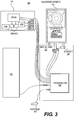
- FIG 3 illustrates a surgical system 300 including a microscope insert 314 according to an alternative embodiment.
- Microscope insert 314 generally corresponds to microscope insert 100 of Figure 1 and is configured to generate stereoscopic images as described herein.
- insert 314 may include two imaging cameras, two display devices, a driver circuit, and other imaging and projection optics for left and right eyes of a user.
- System 300 further includes a medical stand 302, an external monitor 312, a foot pedal 308, and a surgical support system 310.
- Medical stand 302 may include a QR image scanner 304 configured to scan QR codes to provide information encoded in the codes.
- Medical stand 302 also includes a processing unit 306, which generally corresponds to processing unit 108 of Figure 1 .
- Processing unit 306 may be included a motherboard with interfaces, such as USB 2,0, USB 3.0, Ethernet, etc.
- Processing unit 306 may include a central processing unit (CPU) with heat sinks, a RAM, a video card, a power supply, a webcam, etc.
- Processing unit 306 is connected to other system components through its communication interfaces, such as USB ports, Ethernet ports, Internet ports, HDMI interfaces, etc.
- processing unit 306 may be connected to microscope insert 314 and external monitor 312 through HDMI interfaces to provide high resolution video/image data to the driver circuit of insert 314 and monitor 312.
- processing unit 306 may also be connected to insert 314 and monitor 312 through USB ports to provide video/image data and control signals.
- Processing unit 306 may be connected to the camera of insert 314 through USB ports to receive video/image data from the camera.
- Foot pedal 308 and other user input devices may be connected to processing unit 306 through one or more USB ports.
- Foot pedal 308 may be operated by a user to provide user input during a surgery. For example, when the user presses foot pedal 308, foot pedal 308 may generate an electronic signal. Upon receiving the electronic signal from foot pedal 308, processing unit 306 may control insert 314 accordingly.
- processing unit 306 may control insert 314 to change the videos/images generated by the display devices of insert 314. With each pressing of foot pedal 308, insert 314 may toggle between two sets of videos/images. Alternatively, insert 314 may cycle through a series of videos/images when foot pedal 308 is pressed. Still alternatively, pedal 308 may have a position sensor that generates a position signal indicating a position of pedal 308 when the user partially presses pedal 308. Upon receiving the position signal from pedal 308, processing unit 306 may determine the current position of pedal 308 and control insert 314 accordingly. Processing unit 308 may control insert 314 to generate a different set of videos/images corresponding to each position of pedal 308.
- processing unit 306 controls insert 314 to generate a first set of videos/images.
- processing unit 306 controls insert 314 to generate a second set of videos/images.
- Surgical support system 310 may include an external data source and other surgical systems, such as a Bausch & Lomb Stellaris surgical system.
- Surgical support system 310 may include biological sensors that collect biological or physiological data of the patient, including, for example, heart rate, blood pressure, electrocardiogram, etc.
- Surgical support system 310 may further include a database that stores information of the patient, including the patient's medical history and healthcare record.
- the database may also include information of the underlying surgical procedure such as pre-operation analysis and planning performed by a physician, data collecting during the surgical procedure, and additional procedures recommended for post-operation follow-ups.
- the database may also include information of the operating physician including his or her identification, association, qualification, etc.
- Surgical support system 310 may be further connected to additional medical devices (not shown) such as an ultrasound imager, a magnetic resonance imaging device, a computed tomography device, etc., to collect additional image data of the patient.
- Processing unit 306 may receive the information and data from surgical support system 310 and controls insert 314 to generate images based on the information and data. For example, processing unit 306 may transmit the additional image data (i.e., ultrasound data, MRI data, CT data, etc.) received from system 310 to the driver circuit of insert 314 and control the driver circuit of insert 314 to render the additional image, through the display devices, along with the microscopic images of the patient provided by the microscope. Processing unit 306 may also generate additional image data representing the biological or physiological data collected from the patient and control insert 314 to render the additional image data through the display devices of insert 314.
- additional image data i.e., ultrasound data, MRI data, CT data, etc.
- Processing unit 306 may also generate additional image data representing the biological or physiological data collected from the patient and control insert 314 to render the additional image data through the display devices of insert 314.
- Figures 4 and 5 illustrate the operation of a microscope insert according to an embodiment using insert 100 as an example.
- microscope insert 100 may be integrated with a microscope 400 that is suitable for various purposes.
- microscope 400 may be a stereoscopic, infinity-corrected, tube microscope.
- microscope insert 100 may be adapted for use in other microscope layouts and stereoscopic devices known in the art.
- Microscope 400 may include a viewing device 402 that allows a user to view images of an object 406 placed under the microscope.
- Viewing device 402 may be a heads-up device including one or more eye pieces, through which the images of the object are presented to the user.
- Microscope 400 further includes a set of lens elements 404 that receive light reflected from the object and form microscopic images of the object based on the reflected light. Lens elements 404 transmit the microscopic images of the object to tubes 406A and 406B of microscope 400. Tubes 406A and 406B form light transmission paths (i.e., light paths) that direct the microscopic image of the object toward viewing device 402.
- the microscopic image may be an analog image in an embodiment.
- the polarizing beam splitters 120A and 120B are disposed in the respective light paths between lens elements 404 and viewing device 402 of the microscope, intercepting light coming from respective tubes 406A and 406B.
- the beam splitters 120A and 120B may also be placed at other locations within the microscope as one of ordinary skill in the art will appreciate.
- beam splitters 120A and 120B may serve two functions in insert 100. First, they may direct a first component of the light signals coming from the object to respective cameras 118A and 118B so that cameras 118A and 118B capture images of the object. Second, they may merge a second component of the light signals coming from the object that is passed through to viewing device 402 with light signals projected from the display devices 110A and 110B.
- Beam splitter 120A/120B splits the light coming up from the object into two portions, directing a first portion (i.e., an S-polarized component S1) towards camera 118A/118B and a second portion (i.e, a P-polarized component P1) towards viewing device 402 of the microscope.
- Lens 112C/112D between beam splitter 120A/120B and camera 118A/118B is used to focus the S-polarized component S1 exiting beam splitter 120A/120B onto the imaging sensor of camera 118A/118B.
- polarizing beam splitter 120A/120B receives light signals representing a microscopic image of the object from lens elements 404 through tubes 406A and 406B.
- Each of polarizing beam splitters 120A and 120B splits incident light signals by allowing one polarized component S1 to reflect and the other polarized component P1 to pass through.
- the polarized component P1 that passes through beam splitter 120A/120B reaches viewing device 402 and provide the user with the microscopic image of the object for viewing.
- the polarized component S1 is reflected by beam splitter 120A/120B toward respective camera 118A/118B through respective tube lens 112C/112D.
- Camera 118A/118B receives the polarized component S1 reflected from beam splitter 120A/120B and converts the optical signals to electronic image data corresponding to the microscopic image of the object.
- Camera 118A/118B may then transmit the electronic image data to processing unit 108 for further processing.
- Beam splitter 120A/120B operates in a similar manner on the display device side.
- display device 110A/110B renders images under the control of the driver circuit and projects light signals corresponding to the images to beam splitter 120A/120B through lens 112A/112B.
- Lens 112A/112B between beam splitter 120A/120B and respective display device 110A/110B converts the light signals projected from display devices 110A/110B to parallel light rays to match the up-ward parallel light rays coming from tube 406A/406B.
- Beam splitter 120A/120B splits the incident light signals coming from display devices 110A/110B, reflecting the S-polarized component S2 of the incident light signals originating from display devices 110A/110B and passing through the P-polarized component P2 to camera 118A/118B.
- the reflected S-polarized component S2 from display devices 110A/110B is then merged or combined with the P-polarized component P1 passed through beam splitter 120A/120B from tube 406A/406B.
- the images of the object provided by the P-polarized component P1 and the images from display device 110A/110B provided by the S-polarized component S2 may be simultaneously viewed by the user through viewing device 402.
- the images generated by display devices 110A/110B appear as overlaid images on the images of the object formed by lens element 404.
- Polarizing element 114 placed between lens 112A/112B and beam splitter 120A/120B is configured to adjust the polarization of those projected parallel rays from lens 112A/112B so as to adjust the ratio of the light component (i.e., the S2 component) reflected by beam splitter 120A/120B to the light component (i.e., the P2 component) passed through to camera 118A/118B.
- the intensity of the S-polarized component S2 may be adjusted relatively to the intensity of the P-polarized component P2.
- the intensity of the S-polarized component S2 may be substantial equal to the P-polarized component P2 so that the light signals projected from display devices 110A/110B are equally split by beam splitter 120A/120B.
- the intensity of the S-polarized component S2 may also be adjusted relatively to the intensity of the P-polarized component P1.
- the images on the display device 110A/110B may be adjusted to be brighter or dimmer with respect to the images of the object when viewed through viewing device 402.
- the user of microscope 400 may view a combined image including the microscopic image of the object and the overlaid image generated by display device 110A/110B.
- the optical components of the microscope insert may be adjusted so that the overlaid image may appear at a projection image plane 410 that substantially overlaps the focal plane of microscope 400 and is located within the depth of field 408 of microscope 400.
- the microscope insert for a stereoscopic microscope includes a set of imaging and projection hardware for each of the right and left tubes of the microscope so as to generate stereoscopic images.
- the insert includes four lenses 112A-112D, lens 112C and 112D configured to focus the images of the object to left and right camera 118A and 118B, and lens 112A and 112B configured to project the images generated by left and right display devices 110A and 110B to beam splitters 120A and 120B.
- these lenses may be incorporated in a lens set.
- the microscope insert may include additional optical components, such as mirrors, prisms, or lenses, in the optical paths between the beam splitters and the cameras or between the beam splitter and the display devices to modify the directions of the light rays.
- the modified light rays may allow the optical components of the insert to be more freely arranged or repositioned so as to fit into a desired mechanical or industrial form.
- Figures 6A and 6B illustrate an embodiment of a microscope insert 600 including additional optical components to steer light rays.
- Figures 6A and 6B shows, respectively, a side view and a top view of major optical elements of microscope insert 600.
- Microscope insert 600 includes two optical channels for rendering images, respectively, for left and right eyes of the user. Although only one optical channel is described here, one of ordinary skill in the art will appreciate that the optical channels include similar elements and operate in similar manor.
- Each optical channel of microscope insert 600 includes a polarizing beam splitter 624 disposed in the corresponding light pathway of the microscope and coupled to the tube of the microscope, from which light reflected by an object enters microscope insert 600.
- a portion (i.e., the S-polarized component S1) of the incident light is diverted to a turning prism 625, which directs the S1 component through imaging lenses 627 on to a camera 604.
- beam splitter 624 may include a polarizer element configured to adjust the ratio of the light component diverted to camera 604 to the light component passed through to the eyepiece.
- the ratio may be, for example, 1:1, 1:2, 1:3, or other desired value.
- the images generated by the processing unit and to be overlaid on the microscopic images of the object are rendered by a projection LCOS display panel 622 illuminated by an RGB LED light source 621.
- the S-polarized light component S2 of the light generated by LED light source 621 is passed through a set of display illumination optics 620 including illumination lenses and a turning prism. From illumination optics 620, the S-polarized light component S2 is reflected at the hypotenuse of a polarizing beam splitter 623 to LCOS display panel 622.
- LCOS display panel 622 acts as an active polarizer.
- the P-polarized light component P2 passes through a projection lens module 628 and a polarizing wave plate 626 to tube polarizing beam splitter 624.
- the P-polarized light component P2 is then directed to camera 604 by tube polarizing beam splitter 624 and steering prism 625.
- the S-polarized light component S2 is diverted and reflected by tube polarizing beam splitter 624 to the eyepiece of the microscope, which then visualizes the microscopic images of the object and the images generated by display panel 622. When viewed through the eyepiece, the images generated by display panel 622 are overlaid on the microscopic images of the object.
- polarizing wave plate 626 may be omitted. Accordingly, the light from LCOS display panel 622 passes through tube polarizing beam splitter 624 without being reflected to the eye piece. instead, the light from LCOS display panel 622 is directed to turning prism 625 and, in turn to, imaging lens 627 and camera 604.
- wave plate 626 can be removed to perform a calibration between display panel 622 and camera 604, Based on calibration, the system may confirm that images generated by display panel 622 are aligned to the image space being measured by camera 604.
- Figures 7A and 7B illustrate an embodiment of a microscope insert 700 that is similar to microscope insert 600 described above.
- the components of microscope insert 700 are packaged and assembled on a base plate 711 so that microscope insert 700 is ready to be installed on a microscope.
- insert 700 includes one or more optical channels, each including components similar to those of insert 600 illustrated in Figures 6A and 6B .
- Each optical channel includes a camera 704 disposed in a camera housing affixed to base plate 711, a set of imaging lenses disposed in a lens tube 705, an imaging steering prism secured to base plate by prism bracket 706, a set of illumination optics disposed in an illumination optics housing 709, a set of projection lenses disposed in a lens tube 710.
- a focus mechanism is provided in imaging lens tube 705 and allows for fine adjustment of the relative position of the imaging lenses therein, for focusing.
- a focus mechanism is also provided in display lens tube 710 and allows for fine adjustment of the position of the projection lenses for focusing.
- Each optical channel further includes an RGB LED light source and a display panel mounted to base plate 711 through a display and RGB LED mounting bracket 714.
- Microscope insert 700 further includes a driver circuit board 707 mounted to base plate 711 through a driver board bracket 708.
- Microscope insert 700 further includes mounting components for mounting onto a microscope.
- insert 700 includes a top mount 701 that may be coupled to the eyepieces of the microscope.
- Top mount 701 may include features that allow the eyepieces to be secured thereon.
- Top mount 701 is secured to base plate 701 through one or more top mount braces.
- Top mount 701 includes one or more microscope tube openings that allow light to pass through from the polarizing beam splitters to the eye pieces of the microscope.
- Top mount 701 further includes a wave plate slot 712 for disposing and securing the wave plate. The wave plate may be easily inserted into wave plate slot or removed therefrom as desired.
- Microscope insert 700 further includes a bottom mount flange 702 that may be coupled and secured to the microscope tube within the body of the microscope.
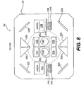
- Figure 8 illustrates a microscope insert 800 according to another embodiment
- light reflected from the object under the microscope is directed from the tubes (e.g., 406A and 406B of Figure 4 ) to respective cameras 818A and 818B by a group of reflective mirrors and prisms 820C, 820D, 822C, and 822D.
- the images generated by display devices 810A and 810B are projected back to beam splitters 816A and 816B by another group of mirrors and prisms 820A, 820B, 822A, and 822B.
- the arrangement in this embodiment allows the components to be disposed on a relatively small base plate that has a relatively small footprint, thereby easing integration in a variety of microscopic systems,
- a polarizer element 814A/814B may be disposed in the light path between display device 810A/810B and beam splitter 816A/816B and is used to vary the amount of light passed through to camera 818A/818B from display device 810A/810B.
- Polarizing element 814A/814B may be a set of polarizers, wave plates, or variable retarders, depending on the output polarization of display devices 810A and 810B.
- display device 810A/810B outputs an S-polarized component, which is then rotated by a 1/2-lambda wave plate in polarizing element 814A/814B so as to be reflected upwardly to the eyepiece for viewing by the user.
- the microscope inserts disclosed herein may create a stereoscopic image.
- the inserts may create separate images for the left and right eyes of the user. The images are shifted with respect to each other to provide the perception of different convergence, resulting in stereoscopic rendering.
- FIG 9 is a schematic diagram of a display driver circuit 900 according to an embodiment.
- Display driver circuit 900 generally corresponds to driver circuit 102 of Figure 1 .
- Driver circuit 900 provides communication interfaces between processing unit 108 and display devices 110A and 110B.
- the functions of driver circuit 900 may include, for example:
- processing unit 108 analyzes image data provided by cameras 118A and 118B and provides inputs to display driver circuit 102 for generating overlaid images through the display devices 110A and 110B.
- processing unit 108 may analyze the image data for registration, tracking, or modeling the object under the microscope. Information derived from the analysis of the image data may then be used to generate and adjust the overlaid images generated by display devices 110A and 110B.
- the microscope insert disclosed herein may be integrated in a microscope for ophthalmic procedures, such as cataract surgery.
- the microscope insert may generate images representing surgery-related information to assist a surgeon to navigate during a cataract surgery.
- the images may be displayed to the user overlaid with the real-time microscopic image of the patients eye. As a result, the surgeon is able to simultaneously view the image of the eye and the overlaid images through the microscope.
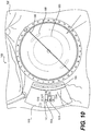
- Figure 10 illustrates an exemplary composite image 1000 rendered by a microscope having a microscope insert described herein, according to an embodiment.
- Image 1000 includes a real-time microscopic image 1020 of a patient's eye as viewed through the microscope and images generated by the microscope insert overlaid on the real-time eye images.
- Microscopic image 1020 of the patient's eye may be an analog image formed by the zoom lens elements of the microscope.
- the overlaid images generated by the microscope insert include graphical representations of information related to the surgical procedure.
- the overlaid images may include prompts or instructions to guide the surgeon during the surgery.
- the overlaid images may include image features indicating an axis of interest 1002 and incision points 1006 and 1008 to guide the surgeon to carry out incision and placement of the artificial lens.
- the overlaid images may also present information including parameters related to the surgery, such as the current operation stage 1012, ultrasound power 1014, vacuum suction 1016, current time, and the like.
- the information may be presented in an image area 1010 near the area of operation.
- Image area 1010 may have a shape that generally conforms to the shape of the patient's eye.
- the processing unit of the microscope insert is configured to track and determine the position, size, and rotation of the patient's eye as it is viewed through the microscope and adjust the position, size, and orientation of the overlaid images accordingly so that the overlaid images remain registered with the patient's eye.
- the microscope insert described here may also receive external data from external data sources and user inputs from user input devices during a surgical procedure, and adjust the overlaid images accordingly.
- the processing unit may receive, from the external data source, demographic information, bio-information, and medical history of the patient.
- the external data source may include a monitoring system that monitors status of surgical equipment or status of the patient, such as heart rate, respiratory rate, blood pressure, eye pressure, and the like, during the surgery.
- the processing unit may receive, from the monitoring system, the external data including real-time information representing the status of the patient and the equipment and presenting the external data as part of the overlaid image displayed to the operating surgeon through the microscope insert.
- the processing unit may receive user inputs from the surgeon through the input devices, such as a joy stick, a foot pedal, a keyboard, a mouse, etc.
- the user inputs may instruct the processing unit to adjust the information displayed in the overlaid images. For example, based on the user inputs, the processing unit may select portions of the external data for display as part of the overlaid images.
- the processing unit may also display prompts or navigation instructions related to the surgical procedure according to the user inputs, For example, when the surgeon completes a step of a surgical procedure and presses the foot pedal, the processing unit may control microscope insert to modify the overlaid images so as to display prompts or instructions for the next step.
- the prompts or instructions may include text or graphical information indicating the next step and may further include data or parameters relevant to the next step.
- the processing unit may also control the microscope insert to generate a warning to alert the surgeon if there are abnormalities during a surgical procedure.
- the warning may be a visual representation such as a warning sign generated by the display devices as part of the overlaid image.
- the warning may also be other visual, audio, or haptic feedback, such as a warning sound or a vibration.
- Figure 11 illustrates a process 1100 for correcting the field of view provided by the display devices and matching it with the field of view of the microscope.
- the microscope generates a microscopic image 1132 having a field of view 1152.
- the microscope insert generates an overlaid image 1134 having a field of view 1154.
- fields of view 1152 and 154 may each have a circular shape.
- Field of view 1152 may have a diameter D1
- field of view 1154 may have a diameter D2.
- overlaid image 1134 generated by the microscope insert and microscopic image 1132 generated by the microscope are displayed to the user through the eyepiece.
- microscopic image 1132 and overlaid image 1134 are combined or overlaid.
- image features of overlaid image 1134 may obscure important image features of microscopic image 1132 or may appear to be disproportional to the image features of microscopic image 1132.
- overlaid image 1134 In order to align the fields of view of the two images, overlaid image 1134 must be adjusted according to the field of view of microscopic image 1132.
- polarization imposed by polarizing element 114 on light signals projected by display device 110A/110B allows a portion (i.e., the P-polarized component P2) of the light signals to pass through polarizing beam splitter 120A/120B.
- the passed-through light from display device 110A/110B is received by camera 118A/118B, which captures overlaid image 1134.
- camera 118A/118B receives light (i.e., the S-polarized component S1) from the object, which is reflected by beam splitter 120A/120B, and captures microscopic image 1132 generated by the microscope.
- the processing unit i.e., processing unit 108 of Figure 1
- the processing unit then applies the image transformations to overlaid image 1134 generated by the display device and control the display device to generate an adjusted overlaid image 1138.
- the field of view provided by the display device is properly aligned with the field of view of the microscope at step 1110.
- Process 1100 may be used to correct any optical misalignment during manufacturing or slight damages from handling.
- the image transformations used by the processing unit may be affine transformations. Typical transformations may include translation, scaling, skewing, rotation, and the like.
- the processor unit may determine a scaling factor for scaling overlaid image 1134 based on a ratio between the diameter D1 of field of view 1152 and the diameter D2 of field of view 1154.
- the processor unit may also determine translation parameters ( ⁇ x and ⁇ y) necessary to align the microscopic image and the overlaid image based on the distance between the circular centers of fields of view 1152 and 1154.
- the microscope insert may provide more precisely placed overlaid images over the microscopic images when viewed through the eyepiece of the microscope.
- the processing unit may monitor changes in the field of view of the microscopic image (i.e., based on the S-polarized component S1) during operation and adjust the overlaid image in such a way to track or follow the field of view of the microscopic image.
- the processing unit may track an anatomical feature of the patient under the microscope and adjust the field of view of the overlaid image to follow the anatomical feature.
- the camera i.e., camera 118A/118B of Figure 1
- the overlaid image generated by the display device i.e., display device 110A/110B
- the camera sensor and the display device are configured to provide oversampling so as to provide sufficient resolutions over the image area that covers the field of view of the microscope.
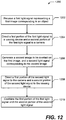
- Figure 12 illustrates a process 1200 for generating an overlaid image over a microscopic image, according to an embodiment.
- Process 1200 may be implemented on the microscope insert (i.e., microscope insert 100) disclosed herein.
- the microscope insert receives a first light signal from a microscope (i.e., microscope 400).
- the first light signal represents a first image corresponding to an object (i.e., object 406) placed under the microscope.
- the first light signal may be received from the zoom lens elements of the microscope through the tube within the body of the microscope.
- the first image may be an analog microscopic image of the object.
- the microscope insert directs a first portion (i.e., the P-polarized component P1) of the first light signal to a viewing device (i.e., viewing device 402) and a second portion (i.e., the S-polarized component S1) of the first light signal to a camera (i.e., camera 118A/1186).
- the first light signal may be split by the polarizing beam splitter (i.e., PBS 120A/120B) of the microscope insert into the first portion and the second portion.
- the polarizing beam splitter may be configured to allow the first portion of the first light signal to pass through to the viewing device and reflect the second portion of the first light signal to the camera within the microscope insert.
- the microscope insert may further include a tube lens (i.e., lens 112C/112D) to focus the second portion of the first light signal onto the camera sensor and/or additional light steering components (i.e., mirrors and prisms) to direct or redirect the second portion of the first light signal to the location of the camera.
- a tube lens i.e., lens 112C/112D
- additional light steering components i.e., mirrors and prisms
- a display device i.e., display device 110A/110B of the microscope insert generates a second image to be overlaid on the first image.
- the second image i.e., the overlaid image
- the second image includes graphical representations indicating information relevant to the object.
- the object is a patient's eye and a surgical procedure (i.e., a cataract surgery) is carried out on the object
- the second image may include, for example, prompts, instructions, parameters, and data relevant to the underlying surgical procedure.
- the display device produces a second light signal representing the second image.
- the microscope insert directs a first portion (i.e., the P-polarized component P2) of the second light signal to the camera and a second portion (i.e., the S-polarized component S2) of the second light signal to the viewing device.
- the second light signal may be split again by the polarizing beam splitter into the first portion and the second portion.
- the polarizing beam splitter may allow the first portion to pass through to the camera and reflect the second portion to the viewing device.
- the microscope insert may further include a tube lens (i.e., lens 112A/112B) between the display device and the polarizing beam splitter to alter (i.e., expand) the second light signal projected by the display device.
- the microscope insert may also include additional light steering components (i.e., mirrors and prisms) to direct the second light signal from the display device to the location of the polarizing beam splitter.
- the microscope insert may also include a polarizer element (i.e., polarizer element 114) between the display device and the polarizing beam splitter.
- the polarizer element may impose polarization on the second light signal so as to adjust the ratio between the first portion of the second light signal, which is passed through to the camera, and the second portion of the second light signal, which is reflected to the viewing device.
- the first portion of the first light signal and the second portion of the second light signal are combined to form a composite image, including the first image corresponding to the object and the second image generated by the display device.
- the second image when viewed through the viewing device, is rendered over the first image.
- the user of the microscope i.e., the surgeon
- the microscope insert may detect any mismatch between a field of the view of the first image and a field of view of the second image.
- the microscope insert may detect the mismatch based on the second portion of the first light signal and the first portion of the second light signal received by the camera. If there is a mismatch, the microscope insert may adjust the second image according to the image transformations described herein so as to match the field of view of the second image with the field of view of the first image.
- microscope insert is described above in the context of a cataract surgery, one of ordinary skill in the art will appreciate that the microscope insert may be integrated in other surgical systems configured to carry out a variety of surgical procedures, such as spinal surgery, ear, nose, and throat (ENT) surgery, neurosurgery, plastic and reconstructive surgery, gynecological or oncological surgery, etc.
- ENT ear, nose, and throat
- the insert may be used for registration, tracking, and image recognition and to generate customized stereoscopic overlaid information relevant to the procedure and a particular patient's anatomy that is not limited to what is disclosed herein. It is intended that the specification and examples be considered as exemplary only, with a true scope of the invention being indicated by the following claims.
Claims (12)
- Insert de microscope (100), comprenant :un séparateur de faisceau configuré pour recevoir une première lumière d'un objet, le séparateur de faisceau dirigeant une première partie de la première lumière dans une première direction vers un dispositif de visualisation, et en dirigeant une deuxième partie de la première lumière dans une deuxième direction ;une caméra configurée pour recevoir, du séparateur de faisceau, la deuxième partie de la première lumière, et générer un premier signal représentant l'objet ;une unité de traitement configurée pour recevoir le premier signal représentant l'objet, et déterminer les caractéristiques de l'objet en analysant le premier signal, l'unité de traitement générant en outre un deuxième signal représentant des informations relatives à l'objet ;un dispositif d'affichage configuré pour recevoir le deuxième signal de l'unité de traitement et générer une représentation graphique des informations sur la base du deuxième signal, le dispositif d'affichage transmettant une deuxième lumière correspondant à la représentation graphique ; etun élément polariseur configuré pour modifier une polarisation de la deuxième lumière depuis le dispositif d'affichage ;dans lequel :le séparateur de faisceau reçoit la deuxième lumière modifiée de l'élément polariseur, et dirige une première partie de la deuxième lumière modifiée dans la première direction au dispositif de visualisation ; etla première partie de la deuxième lumière modifiée et la première partie de la première lumière provenant de l'objet se combinent pour une visualisation simultanée de la représentation graphique et de l'objet par l'utilisateur ;caractérisé en ce que :le séparateur de faisceau est configuré en outre pour diriger une deuxième partie de la deuxième lumière modifiée dans la deuxième direction vers la caméra, et la caméra générant, sur la base de la deuxième lumière de la deuxième lumière modifiée, un troisième signal représentant la représentation graphique générée par le dispositif d'affichage ;l'unité de traitement étant configurée en outre pour :déterminer un champ de vue sur la base du premier signal provenant de la caméra ;comparer le troisième signal et le premier signal ; etajuster la représentation graphique générée par le dispositif d'affichage sur la base de la comparaison ; etl'élément polariseur étant configuré pour ajuster la polarisation de la deuxième lumière depuis le dispositif d'affichage, de façon à ajuster un ratio entre la première partie de la deuxième lumière modifiée et la deuxième partie de la deuxième lumière modifiée.
- Insert de microscope (100) selon la revendication 1, comprenant en outre :un premier objectif disposé entre le séparateur de faisceau et la caméra pour diriger la deuxième partie de la première lumière de l'objet à la caméra ; etun deuxième objectif disposé entre le séparateur de faisceau et le dispositif d'affichage pour transformer la deuxième lumière provenant du dispositif d'affichage en rayons de lumière substantiellement parallèles.
- Insert de microscope (100) selon la revendication 1, la première direction et la deuxième direction étant perpendiculaires.
- Insert de microscope (100) selon la revendication 1, la première partie et la deuxième partie de la première lumière ayant une polarisation différente.
- Insert de microscope (100) selon la revendication 1, comprenant en outre un ou plusieurs éléments d'orientation de la lumière pour diriger la deuxième partie de la première lumière de l'objet à la caméra, en option l'un ou plusieurs éléments d'orientation de la lumière comprenant au moins un d'un miroir ou d'un prisme.
- Insert de microscope (100) selon la revendication 1, comprenant en outre un ou plusieurs éléments d'orientation de la lumière pour diriger la deuxième partie de la deuxième lumière modifiée vers la caméra, en option l'un ou plusieurs éléments d'orientation de la lumière comprenant au moins un d'un miroir ou d'un prisme.
- Insert de microscope (100) selon la revendication 1, comprenant en outre un circuit de commande configuré pour recevoir des données d'image et des signaux de commande de l'unité de traitement, et couplé au dispositif d'affichage pour commander le dispositif d'affichage conformément aux données d'image et aux signaux de commande.
- Insert de microscope (100) selon la revendication 1, comprenant en outre un socle pour le montage d'un ou plusieurs des suivants : séparateur de faisceau, caméra, unité de traitement, dispositif d'affichage, et circuit de commande.
- Insert de microscope (100) selon la revendication 8, le socle comprenant une première interface de montage pour le montage de l'insert de microscope sur un microscope, de sorte que le séparateur de faisceau intercepte un trajet de lumière du microscope.
- Insert de microscope (100) selon la revendication 9, le séparateur de faisceau étant configuré pour recevoir la lumière de l'objet à travers un jeu d'éléments d'objectifs du microscope.
- Insert de microscope (100) selon la revendication 9, comprenant en outre une deuxième interface de montage pour le montage du dispositif de visualisation sur l'insert de microscope.
- Insert de microscope (100) selon la revendication 1, comprenant :un premier canal et un deuxième canal, les premier et deuxième canaux comprenant chacun :un séparateur de faisceau configuré pour recevoir la première lumière d'un objet, le séparateur de faisceau dirigeant une première partie de la première lumière dans une première direction vers un dispositif de visualisation, et dirigeant une deuxième partie de la première lumière dans une deuxième direction ; etune caméra configurée pour recevoir la deuxième partie de la première lumière provenant du séparateur de faisceau, et générer un premier signal représentant l'objet ;un dispositif d'affichage ; et un élément polariseur ; etune unité de traitement configurée pour recevoir le premier signal représentant l'objet et établir des caractéristiques de l'objet en analysant le premier signal, l'unité de traitement générant en outre un deuxième signal représentant des informations relatives à l'objet.
Applications Claiming Priority (2)
| Application Number | Priority Date | Filing Date | Title |
|---|---|---|---|
| US201461952793P | 2014-03-13 | 2014-03-13 | |
| PCT/US2015/020584 WO2015138988A1 (fr) | 2014-03-13 | 2015-03-13 | Insert de microscope |
Publications (3)
| Publication Number | Publication Date |
|---|---|
| EP3117258A1 EP3117258A1 (fr) | 2017-01-18 |
| EP3117258A4 EP3117258A4 (fr) | 2017-11-22 |
| EP3117258B1 true EP3117258B1 (fr) | 2019-01-02 |
Family
ID=54072504
Family Applications (1)
| Application Number | Title | Priority Date | Filing Date |
|---|---|---|---|
| EP15760909.0A Not-in-force EP3117258B1 (fr) | 2014-03-13 | 2015-03-13 | Insert de microscope |
Country Status (3)
| Country | Link |
|---|---|
| US (1) | US10254528B2 (fr) |
| EP (1) | EP3117258B1 (fr) |
| WO (1) | WO2015138988A1 (fr) |
Families Citing this family (2)
| Publication number | Priority date | Publication date | Assignee | Title |
|---|---|---|---|---|
| CN111679422B (zh) * | 2020-06-09 | 2023-11-03 | 腾讯科技(深圳)有限公司 | 显微镜、图像处理系统及图像处理方法 |
| WO2023284946A1 (fr) * | 2021-07-13 | 2023-01-19 | Haag-Streit Ag | Microscope ophtalmique ou chirurgical avec dispositif d'affichage et caméra |
Family Cites Families (18)
| Publication number | Priority date | Publication date | Assignee | Title |
|---|---|---|---|---|
| DE4134481C2 (de) | 1991-10-18 | 1998-04-09 | Zeiss Carl Fa | Operationsmikroskop zur rechnergestützten, stereotaktischen Mikrochirurgie |
| US7044602B2 (en) | 2002-05-30 | 2006-05-16 | Visx, Incorporated | Methods and systems for tracking a torsional orientation and position of an eye |
| DE50206432D1 (de) | 2001-02-23 | 2006-05-24 | Leica Microsystems Schweiz Ag | Erweiterte Blendensteuerung für Bildeinblendungen in einem Stereomikroskop |
| DE102004055683B4 (de) | 2004-10-26 | 2006-09-07 | Carl Zeiss Surgical Gmbh | Augenchirurgie-Mikroskopiesystem und Verfahren hierzu |
| US7800820B2 (en) | 2006-06-30 | 2010-09-21 | Richard Awdeh | Microscope viewing device |
| US7729049B2 (en) | 2007-05-26 | 2010-06-01 | Zeta Instruments, Inc. | 3-d optical microscope |
| WO2009029638A1 (fr) | 2007-08-27 | 2009-03-05 | Videntity Systems, Inc. | Reconnaissance d'iris |
| US10398599B2 (en) | 2007-10-05 | 2019-09-03 | Topcon Medical Laser Systems Inc. | Semi-automated ophthalmic photocoagulation method and apparatus |
| DE102008034490B4 (de) | 2008-07-24 | 2018-12-20 | Carl Zeiss Meditec Ag | Augenchirurgiesystem und Verfahren zur Vorbereitung und Durchführung einer Augenoperation |
| EP2184005B1 (fr) | 2008-10-22 | 2011-05-18 | SensoMotoric Instruments Gesellschaft für innovative Sensorik mbH | Appareil et procédé pour le traitement d'images pour chirurgie des yeux assistée par ordinateur |
| US8308298B2 (en) | 2009-06-24 | 2012-11-13 | Carl Zeiss Meditec Ag | Microscopy system for eye surgery |
| US9492322B2 (en) | 2009-11-16 | 2016-11-15 | Alcon Lensx, Inc. | Imaging surgical target tissue by nonlinear scanning |
| JP5511516B2 (ja) | 2010-05-31 | 2014-06-04 | 株式会社ニデック | 眼科装置 |
| JP2012152469A (ja) | 2011-01-27 | 2012-08-16 | Nidek Co Ltd | 眼科用手術顕微鏡 |
| US20120330129A1 (en) * | 2011-06-23 | 2012-12-27 | Richard Awdeh | Medical visualization systems and related methods of use |
| WO2013052259A1 (fr) | 2011-10-05 | 2013-04-11 | Alcon Research, Ltd. | Dispositif d'affichage tête haute chirurgicale qui est ajustable dans un champ de vision tridimensionnel |
| JP2015515025A (ja) | 2012-04-17 | 2015-05-21 | エンデュア メディカル インコーポレイテッドEndure Medical Inc. | 立体ビーム分割器 |
| DE102014201571B4 (de) | 2014-01-29 | 2022-08-04 | Carl Zeiss Meditec Ag | Modul für die Dateneinspiegelung in einer Visualisierungsvorrichtung, Visualisierungsvorrichtung und Verfahren zum Anpassen der Vorrichtung |
-
2015
- 2015-03-13 EP EP15760909.0A patent/EP3117258B1/fr not_active Not-in-force
- 2015-03-13 US US15/123,041 patent/US10254528B2/en not_active Expired - Fee Related
- 2015-03-13 WO PCT/US2015/020584 patent/WO2015138988A1/fr active Application Filing
Non-Patent Citations (1)
| Title |
|---|
| None * |
Also Published As
| Publication number | Publication date |
|---|---|
| WO2015138988A1 (fr) | 2015-09-17 |
| US10254528B2 (en) | 2019-04-09 |
| EP3117258A1 (fr) | 2017-01-18 |
| US20170075100A1 (en) | 2017-03-16 |
| EP3117258A4 (fr) | 2017-11-22 |
Similar Documents
| Publication | Publication Date | Title |
|---|---|---|
| JP7225300B2 (ja) | 立体視覚化カメラ及びプラットフォーム | |
| US20240080433A1 (en) | Systems and methods for mediated-reality surgical visualization | |
| US9967475B2 (en) | Head-mounted displaying of magnified images locked on an object of interest | |
| KR101476820B1 (ko) | 3d 비디오 현미경 장치 | |
| EP3267892A1 (fr) | Procédés et systèmes pour le recalage à l'aide d'un insert de microscope | |
| US20170164829A1 (en) | Registration Using a Microscope Insert | |
| US20140187857A1 (en) | Apparatus and Methods for Enhanced Visualization and Control in Minimally Invasive Surgery | |
| US11571109B2 (en) | Medical observation device | |
| EP3117258B1 (fr) | Insert de microscope | |
| JP3583448B2 (ja) | 手術用顕微鏡装置 | |
| WO2019198293A1 (fr) | Système de microscope et dispositif source de lumière médicale | |
| CN111103679A (zh) | 显微镜外置双路同步平行光3d图像实时采集装置、系统 | |
| US20230179755A1 (en) | Stereoscopic imaging apparatus with multiple fixed magnification levels | |
| US20230109895A1 (en) | Surgery 3D Visualization Apparatus | |
| JP2015201771A (ja) | 投射型表示装置および制御方法 | |
| WO2024072925A2 (fr) | Stabilisation d'image optique et alignement actif de capteurs dans des systèmes de caméra endoscopique et leurs procédés d'utilisation | |
| CN115868921A (zh) | 视线检测设备和摄像设备 | |
| JP2017199330A (ja) | 機器表示情報収集管理システム |
Legal Events
| Date | Code | Title | Description |
|---|---|---|---|
| STAA | Information on the status of an ep patent application or granted ep patent |
Free format text: STATUS: THE INTERNATIONAL PUBLICATION HAS BEEN MADE |
|
| PUAI | Public reference made under article 153(3) epc to a published international application that has entered the european phase |
Free format text: ORIGINAL CODE: 0009012 |
|
| STAA | Information on the status of an ep patent application or granted ep patent |
Free format text: STATUS: REQUEST FOR EXAMINATION WAS MADE |
|
| 17P | Request for examination filed |
Effective date: 20160901 |
|
| AK | Designated contracting states |
Kind code of ref document: A1 Designated state(s): AL AT BE BG CH CY CZ DE DK EE ES FI FR GB GR HR HU IE IS IT LI LT LU LV MC MK MT NL NO PL PT RO RS SE SI SK SM TR |
|
| AX | Request for extension of the european patent |
Extension state: BA ME |
|
| DAV | Request for validation of the european patent (deleted) | ||
| DAX | Request for extension of the european patent (deleted) | ||
| A4 | Supplementary search report drawn up and despatched |
Effective date: 20171019 |
|
| RIC1 | Information provided on ipc code assigned before grant |
Ipc: A61B 3/14 20060101ALI20171013BHEP Ipc: G02B 27/14 20060101ALI20171013BHEP Ipc: G02B 27/28 20060101ALI20171013BHEP Ipc: A61B 3/00 20060101ALI20171013BHEP Ipc: G02B 27/01 20060101ALI20171013BHEP Ipc: G02B 21/36 20060101ALI20171013BHEP Ipc: G02B 21/00 20060101ALI20171013BHEP Ipc: G02B 27/22 20060101ALI20171013BHEP Ipc: G02B 21/22 20060101AFI20171013BHEP Ipc: A61B 3/13 20060101ALI20171013BHEP Ipc: G02B 21/18 20060101ALI20171013BHEP |
|
| GRAP | Despatch of communication of intention to grant a patent |
Free format text: ORIGINAL CODE: EPIDOSNIGR1 |
|
| STAA | Information on the status of an ep patent application or granted ep patent |
Free format text: STATUS: GRANT OF PATENT IS INTENDED |
|
| INTG | Intention to grant announced |
Effective date: 20180713 |
|
| GRAS | Grant fee paid |
Free format text: ORIGINAL CODE: EPIDOSNIGR3 |
|
| GRAA | (expected) grant |
Free format text: ORIGINAL CODE: 0009210 |
|
| STAA | Information on the status of an ep patent application or granted ep patent |
Free format text: STATUS: THE PATENT HAS BEEN GRANTED |
|
| AK | Designated contracting states |
Kind code of ref document: B1 Designated state(s): AL AT BE BG CH CY CZ DE DK EE ES FI FR GB GR HR HU IE IS IT LI LT LU LV MC MK MT NL NO PL PT RO RS SE SI SK SM TR |
|
| REG | Reference to a national code |
Ref country code: GB Ref legal event code: FG4D |
|
| REG | Reference to a national code |
Ref country code: CH Ref legal event code: EP Ref country code: AT Ref legal event code: REF Ref document number: 1085127 Country of ref document: AT Kind code of ref document: T Effective date: 20190115 |
|
| REG | Reference to a national code |
Ref country code: IE Ref legal event code: FG4D |
|
| REG | Reference to a national code |
Ref country code: DE Ref legal event code: R096 Ref document number: 602015022833 Country of ref document: DE |
|
| PGFP | Annual fee paid to national office [announced via postgrant information from national office to epo] |
Ref country code: DE Payment date: 20190330 Year of fee payment: 5 |
|
| REG | Reference to a national code |
Ref country code: NL Ref legal event code: MP Effective date: 20190102 |
|
| REG | Reference to a national code |
Ref country code: LT Ref legal event code: MG4D |
|
| REG | Reference to a national code |
Ref country code: AT Ref legal event code: MK05 Ref document number: 1085127 Country of ref document: AT Kind code of ref document: T Effective date: 20190102 |
|
| PG25 | Lapsed in a contracting state [announced via postgrant information from national office to epo] |
Ref country code: NL Free format text: LAPSE BECAUSE OF FAILURE TO SUBMIT A TRANSLATION OF THE DESCRIPTION OR TO PAY THE FEE WITHIN THE PRESCRIBED TIME-LIMIT Effective date: 20190102 |
|
| PG25 | Lapsed in a contracting state [announced via postgrant information from national office to epo] |
Ref country code: PT Free format text: LAPSE BECAUSE OF FAILURE TO SUBMIT A TRANSLATION OF THE DESCRIPTION OR TO PAY THE FEE WITHIN THE PRESCRIBED TIME-LIMIT Effective date: 20190502 Ref country code: SE Free format text: LAPSE BECAUSE OF FAILURE TO SUBMIT A TRANSLATION OF THE DESCRIPTION OR TO PAY THE FEE WITHIN THE PRESCRIBED TIME-LIMIT Effective date: 20190102 Ref country code: ES Free format text: LAPSE BECAUSE OF FAILURE TO SUBMIT A TRANSLATION OF THE DESCRIPTION OR TO PAY THE FEE WITHIN THE PRESCRIBED TIME-LIMIT Effective date: 20190102 Ref country code: NO Free format text: LAPSE BECAUSE OF FAILURE TO SUBMIT A TRANSLATION OF THE DESCRIPTION OR TO PAY THE FEE WITHIN THE PRESCRIBED TIME-LIMIT Effective date: 20190402 Ref country code: LT Free format text: LAPSE BECAUSE OF FAILURE TO SUBMIT A TRANSLATION OF THE DESCRIPTION OR TO PAY THE FEE WITHIN THE PRESCRIBED TIME-LIMIT Effective date: 20190102 Ref country code: FI Free format text: LAPSE BECAUSE OF FAILURE TO SUBMIT A TRANSLATION OF THE DESCRIPTION OR TO PAY THE FEE WITHIN THE PRESCRIBED TIME-LIMIT Effective date: 20190102 Ref country code: PL Free format text: LAPSE BECAUSE OF FAILURE TO SUBMIT A TRANSLATION OF THE DESCRIPTION OR TO PAY THE FEE WITHIN THE PRESCRIBED TIME-LIMIT Effective date: 20190102 |
|
| PG25 | Lapsed in a contracting state [announced via postgrant information from national office to epo] |
Ref country code: BG Free format text: LAPSE BECAUSE OF FAILURE TO SUBMIT A TRANSLATION OF THE DESCRIPTION OR TO PAY THE FEE WITHIN THE PRESCRIBED TIME-LIMIT Effective date: 20190402 Ref country code: HR Free format text: LAPSE BECAUSE OF FAILURE TO SUBMIT A TRANSLATION OF THE DESCRIPTION OR TO PAY THE FEE WITHIN THE PRESCRIBED TIME-LIMIT Effective date: 20190102 Ref country code: GR Free format text: LAPSE BECAUSE OF FAILURE TO SUBMIT A TRANSLATION OF THE DESCRIPTION OR TO PAY THE FEE WITHIN THE PRESCRIBED TIME-LIMIT Effective date: 20190403 Ref country code: IS Free format text: LAPSE BECAUSE OF FAILURE TO SUBMIT A TRANSLATION OF THE DESCRIPTION OR TO PAY THE FEE WITHIN THE PRESCRIBED TIME-LIMIT Effective date: 20190502 Ref country code: LV Free format text: LAPSE BECAUSE OF FAILURE TO SUBMIT A TRANSLATION OF THE DESCRIPTION OR TO PAY THE FEE WITHIN THE PRESCRIBED TIME-LIMIT Effective date: 20190102 Ref country code: RS Free format text: LAPSE BECAUSE OF FAILURE TO SUBMIT A TRANSLATION OF THE DESCRIPTION OR TO PAY THE FEE WITHIN THE PRESCRIBED TIME-LIMIT Effective date: 20190102 |
|
| REG | Reference to a national code |
Ref country code: DE Ref legal event code: R097 Ref document number: 602015022833 Country of ref document: DE |
|
| PG25 | Lapsed in a contracting state [announced via postgrant information from national office to epo] |
Ref country code: CZ Free format text: LAPSE BECAUSE OF FAILURE TO SUBMIT A TRANSLATION OF THE DESCRIPTION OR TO PAY THE FEE WITHIN THE PRESCRIBED TIME-LIMIT Effective date: 20190102 Ref country code: IT Free format text: LAPSE BECAUSE OF FAILURE TO SUBMIT A TRANSLATION OF THE DESCRIPTION OR TO PAY THE FEE WITHIN THE PRESCRIBED TIME-LIMIT Effective date: 20190102 Ref country code: RO Free format text: LAPSE BECAUSE OF FAILURE TO SUBMIT A TRANSLATION OF THE DESCRIPTION OR TO PAY THE FEE WITHIN THE PRESCRIBED TIME-LIMIT Effective date: 20190102 Ref country code: SK Free format text: LAPSE BECAUSE OF FAILURE TO SUBMIT A TRANSLATION OF THE DESCRIPTION OR TO PAY THE FEE WITHIN THE PRESCRIBED TIME-LIMIT Effective date: 20190102 Ref country code: AT Free format text: LAPSE BECAUSE OF FAILURE TO SUBMIT A TRANSLATION OF THE DESCRIPTION OR TO PAY THE FEE WITHIN THE PRESCRIBED TIME-LIMIT Effective date: 20190102 Ref country code: DK Free format text: LAPSE BECAUSE OF FAILURE TO SUBMIT A TRANSLATION OF THE DESCRIPTION OR TO PAY THE FEE WITHIN THE PRESCRIBED TIME-LIMIT Effective date: 20190102 Ref country code: EE Free format text: LAPSE BECAUSE OF FAILURE TO SUBMIT A TRANSLATION OF THE DESCRIPTION OR TO PAY THE FEE WITHIN THE PRESCRIBED TIME-LIMIT Effective date: 20190102 Ref country code: MC Free format text: LAPSE BECAUSE OF FAILURE TO SUBMIT A TRANSLATION OF THE DESCRIPTION OR TO PAY THE FEE WITHIN THE PRESCRIBED TIME-LIMIT Effective date: 20190102 Ref country code: AL Free format text: LAPSE BECAUSE OF FAILURE TO SUBMIT A TRANSLATION OF THE DESCRIPTION OR TO PAY THE FEE WITHIN THE PRESCRIBED TIME-LIMIT Effective date: 20190102 |
|
| PGFP | Annual fee paid to national office [announced via postgrant information from national office to epo] |
Ref country code: GB Payment date: 20190401 Year of fee payment: 5 |
|
| REG | Reference to a national code |
Ref country code: CH Ref legal event code: PL |
|
| PLBE | No opposition filed within time limit |
Free format text: ORIGINAL CODE: 0009261 |
|
| STAA | Information on the status of an ep patent application or granted ep patent |
Free format text: STATUS: NO OPPOSITION FILED WITHIN TIME LIMIT |
|
| PG25 | Lapsed in a contracting state [announced via postgrant information from national office to epo] |
Ref country code: LU Free format text: LAPSE BECAUSE OF NON-PAYMENT OF DUE FEES Effective date: 20190313 Ref country code: SM Free format text: LAPSE BECAUSE OF FAILURE TO SUBMIT A TRANSLATION OF THE DESCRIPTION OR TO PAY THE FEE WITHIN THE PRESCRIBED TIME-LIMIT Effective date: 20190102 |
|
| REG | Reference to a national code |
Ref country code: BE Ref legal event code: MM Effective date: 20190331 |
|
| 26N | No opposition filed |
Effective date: 20191003 |
|
| PG25 | Lapsed in a contracting state [announced via postgrant information from national office to epo] |
Ref country code: LI Free format text: LAPSE BECAUSE OF NON-PAYMENT OF DUE FEES Effective date: 20190331 Ref country code: CH Free format text: LAPSE BECAUSE OF NON-PAYMENT OF DUE FEES Effective date: 20190331 Ref country code: IE Free format text: LAPSE BECAUSE OF NON-PAYMENT OF DUE FEES Effective date: 20190313 |
|
| PG25 | Lapsed in a contracting state [announced via postgrant information from national office to epo] |
Ref country code: FR Free format text: LAPSE BECAUSE OF NON-PAYMENT OF DUE FEES Effective date: 20190331 Ref country code: SI Free format text: LAPSE BECAUSE OF FAILURE TO SUBMIT A TRANSLATION OF THE DESCRIPTION OR TO PAY THE FEE WITHIN THE PRESCRIBED TIME-LIMIT Effective date: 20190102 Ref country code: BE Free format text: LAPSE BECAUSE OF NON-PAYMENT OF DUE FEES Effective date: 20190331 |
|
| PG25 | Lapsed in a contracting state [announced via postgrant information from national office to epo] |
Ref country code: TR Free format text: LAPSE BECAUSE OF FAILURE TO SUBMIT A TRANSLATION OF THE DESCRIPTION OR TO PAY THE FEE WITHIN THE PRESCRIBED TIME-LIMIT Effective date: 20190102 |
|
| PG25 | Lapsed in a contracting state [announced via postgrant information from national office to epo] |
Ref country code: MT Free format text: LAPSE BECAUSE OF NON-PAYMENT OF DUE FEES Effective date: 20190313 |
|
| REG | Reference to a national code |
Ref country code: DE Ref legal event code: R119 Ref document number: 602015022833 Country of ref document: DE |
|
| PG25 | Lapsed in a contracting state [announced via postgrant information from national office to epo] |
Ref country code: DE Free format text: LAPSE BECAUSE OF NON-PAYMENT OF DUE FEES Effective date: 20201001 |
|
| GBPC | Gb: european patent ceased through non-payment of renewal fee |
Effective date: 20200313 |
|
| PG25 | Lapsed in a contracting state [announced via postgrant information from national office to epo] |
Ref country code: GB Free format text: LAPSE BECAUSE OF NON-PAYMENT OF DUE FEES Effective date: 20200313 |
|
| PG25 | Lapsed in a contracting state [announced via postgrant information from national office to epo] |
Ref country code: CY Free format text: LAPSE BECAUSE OF FAILURE TO SUBMIT A TRANSLATION OF THE DESCRIPTION OR TO PAY THE FEE WITHIN THE PRESCRIBED TIME-LIMIT Effective date: 20190102 |
|
| PG25 | Lapsed in a contracting state [announced via postgrant information from national office to epo] |
Ref country code: HU Free format text: LAPSE BECAUSE OF FAILURE TO SUBMIT A TRANSLATION OF THE DESCRIPTION OR TO PAY THE FEE WITHIN THE PRESCRIBED TIME-LIMIT; INVALID AB INITIO Effective date: 20150313 |
|
| PG25 | Lapsed in a contracting state [announced via postgrant information from national office to epo] |
Ref country code: MK Free format text: LAPSE BECAUSE OF FAILURE TO SUBMIT A TRANSLATION OF THE DESCRIPTION OR TO PAY THE FEE WITHIN THE PRESCRIBED TIME-LIMIT Effective date: 20190102 |