EP3117136B1 - Valve unit for gas container with a pressure-indicating or autonomy-indicating device near the top - Google Patents
Valve unit for gas container with a pressure-indicating or autonomy-indicating device near the top Download PDFInfo
- Publication number
- EP3117136B1 EP3117136B1 EP15714564.0A EP15714564A EP3117136B1 EP 3117136 B1 EP3117136 B1 EP 3117136B1 EP 15714564 A EP15714564 A EP 15714564A EP 3117136 B1 EP3117136 B1 EP 3117136B1
- Authority
- EP
- European Patent Office
- Prior art keywords
- gas
- pressure
- passage
- autonomy
- valve
- Prior art date
- Legal status (The legal status is an assumption and is not a legal conclusion. Google has not performed a legal analysis and makes no representation as to the accuracy of the status listed.)
- Active
Links
Images
Classifications
-
- F—MECHANICAL ENGINEERING; LIGHTING; HEATING; WEAPONS; BLASTING
- F17—STORING OR DISTRIBUTING GASES OR LIQUIDS
- F17C—VESSELS FOR CONTAINING OR STORING COMPRESSED, LIQUEFIED OR SOLIDIFIED GASES; FIXED-CAPACITY GAS-HOLDERS; FILLING VESSELS WITH, OR DISCHARGING FROM VESSELS, COMPRESSED, LIQUEFIED, OR SOLIDIFIED GASES
- F17C13/00—Details of vessels or of the filling or discharging of vessels
- F17C13/04—Arrangement or mounting of valves
-
- F—MECHANICAL ENGINEERING; LIGHTING; HEATING; WEAPONS; BLASTING
- F17—STORING OR DISTRIBUTING GASES OR LIQUIDS
- F17C—VESSELS FOR CONTAINING OR STORING COMPRESSED, LIQUEFIED OR SOLIDIFIED GASES; FIXED-CAPACITY GAS-HOLDERS; FILLING VESSELS WITH, OR DISCHARGING FROM VESSELS, COMPRESSED, LIQUEFIED, OR SOLIDIFIED GASES
- F17C2201/00—Vessel construction, in particular geometry, arrangement or size
- F17C2201/01—Shape
- F17C2201/0104—Shape cylindrical
- F17C2201/0109—Shape cylindrical with exteriorly curved end-piece
-
- F—MECHANICAL ENGINEERING; LIGHTING; HEATING; WEAPONS; BLASTING
- F17—STORING OR DISTRIBUTING GASES OR LIQUIDS
- F17C—VESSELS FOR CONTAINING OR STORING COMPRESSED, LIQUEFIED OR SOLIDIFIED GASES; FIXED-CAPACITY GAS-HOLDERS; FILLING VESSELS WITH, OR DISCHARGING FROM VESSELS, COMPRESSED, LIQUEFIED, OR SOLIDIFIED GASES
- F17C2201/00—Vessel construction, in particular geometry, arrangement or size
- F17C2201/03—Orientation
- F17C2201/032—Orientation with substantially vertical main axis
-
- F—MECHANICAL ENGINEERING; LIGHTING; HEATING; WEAPONS; BLASTING
- F17—STORING OR DISTRIBUTING GASES OR LIQUIDS
- F17C—VESSELS FOR CONTAINING OR STORING COMPRESSED, LIQUEFIED OR SOLIDIFIED GASES; FIXED-CAPACITY GAS-HOLDERS; FILLING VESSELS WITH, OR DISCHARGING FROM VESSELS, COMPRESSED, LIQUEFIED, OR SOLIDIFIED GASES
- F17C2201/00—Vessel construction, in particular geometry, arrangement or size
- F17C2201/05—Size
- F17C2201/058—Size portable (<30 l)
-
- F—MECHANICAL ENGINEERING; LIGHTING; HEATING; WEAPONS; BLASTING
- F17—STORING OR DISTRIBUTING GASES OR LIQUIDS
- F17C—VESSELS FOR CONTAINING OR STORING COMPRESSED, LIQUEFIED OR SOLIDIFIED GASES; FIXED-CAPACITY GAS-HOLDERS; FILLING VESSELS WITH, OR DISCHARGING FROM VESSELS, COMPRESSED, LIQUEFIED, OR SOLIDIFIED GASES
- F17C2203/00—Vessel construction, in particular walls or details thereof
- F17C2203/06—Materials for walls or layers thereof; Properties or structures of walls or their materials
- F17C2203/0602—Wall structures; Special features thereof
- F17C2203/0612—Wall structures
- F17C2203/0614—Single wall
- F17C2203/0617—Single wall with one layer
-
- F—MECHANICAL ENGINEERING; LIGHTING; HEATING; WEAPONS; BLASTING
- F17—STORING OR DISTRIBUTING GASES OR LIQUIDS
- F17C—VESSELS FOR CONTAINING OR STORING COMPRESSED, LIQUEFIED OR SOLIDIFIED GASES; FIXED-CAPACITY GAS-HOLDERS; FILLING VESSELS WITH, OR DISCHARGING FROM VESSELS, COMPRESSED, LIQUEFIED, OR SOLIDIFIED GASES
- F17C2203/00—Vessel construction, in particular walls or details thereof
- F17C2203/06—Materials for walls or layers thereof; Properties or structures of walls or their materials
- F17C2203/0634—Materials for walls or layers thereof
- F17C2203/0636—Metals
- F17C2203/0639—Steels
-
- F—MECHANICAL ENGINEERING; LIGHTING; HEATING; WEAPONS; BLASTING
- F17—STORING OR DISTRIBUTING GASES OR LIQUIDS
- F17C—VESSELS FOR CONTAINING OR STORING COMPRESSED, LIQUEFIED OR SOLIDIFIED GASES; FIXED-CAPACITY GAS-HOLDERS; FILLING VESSELS WITH, OR DISCHARGING FROM VESSELS, COMPRESSED, LIQUEFIED, OR SOLIDIFIED GASES
- F17C2203/00—Vessel construction, in particular walls or details thereof
- F17C2203/06—Materials for walls or layers thereof; Properties or structures of walls or their materials
- F17C2203/0634—Materials for walls or layers thereof
- F17C2203/0636—Metals
- F17C2203/0646—Aluminium
-
- F—MECHANICAL ENGINEERING; LIGHTING; HEATING; WEAPONS; BLASTING
- F17—STORING OR DISTRIBUTING GASES OR LIQUIDS
- F17C—VESSELS FOR CONTAINING OR STORING COMPRESSED, LIQUEFIED OR SOLIDIFIED GASES; FIXED-CAPACITY GAS-HOLDERS; FILLING VESSELS WITH, OR DISCHARGING FROM VESSELS, COMPRESSED, LIQUEFIED, OR SOLIDIFIED GASES
- F17C2203/00—Vessel construction, in particular walls or details thereof
- F17C2203/06—Materials for walls or layers thereof; Properties or structures of walls or their materials
- F17C2203/0634—Materials for walls or layers thereof
- F17C2203/0636—Metals
- F17C2203/0648—Alloys or compositions of metals
-
- F—MECHANICAL ENGINEERING; LIGHTING; HEATING; WEAPONS; BLASTING
- F17—STORING OR DISTRIBUTING GASES OR LIQUIDS
- F17C—VESSELS FOR CONTAINING OR STORING COMPRESSED, LIQUEFIED OR SOLIDIFIED GASES; FIXED-CAPACITY GAS-HOLDERS; FILLING VESSELS WITH, OR DISCHARGING FROM VESSELS, COMPRESSED, LIQUEFIED, OR SOLIDIFIED GASES
- F17C2203/00—Vessel construction, in particular walls or details thereof
- F17C2203/06—Materials for walls or layers thereof; Properties or structures of walls or their materials
- F17C2203/0634—Materials for walls or layers thereof
- F17C2203/0658—Synthetics
- F17C2203/0663—Synthetics in form of fibers or filaments
-
- F—MECHANICAL ENGINEERING; LIGHTING; HEATING; WEAPONS; BLASTING
- F17—STORING OR DISTRIBUTING GASES OR LIQUIDS
- F17C—VESSELS FOR CONTAINING OR STORING COMPRESSED, LIQUEFIED OR SOLIDIFIED GASES; FIXED-CAPACITY GAS-HOLDERS; FILLING VESSELS WITH, OR DISCHARGING FROM VESSELS, COMPRESSED, LIQUEFIED, OR SOLIDIFIED GASES
- F17C2205/00—Vessel construction, in particular mounting arrangements, attachments or identifications means
- F17C2205/01—Mounting arrangements
- F17C2205/0153—Details of mounting arrangements
- F17C2205/0157—Details of mounting arrangements for transport
- F17C2205/0165—Details of mounting arrangements for transport with handgrip
-
- F—MECHANICAL ENGINEERING; LIGHTING; HEATING; WEAPONS; BLASTING
- F17—STORING OR DISTRIBUTING GASES OR LIQUIDS
- F17C—VESSELS FOR CONTAINING OR STORING COMPRESSED, LIQUEFIED OR SOLIDIFIED GASES; FIXED-CAPACITY GAS-HOLDERS; FILLING VESSELS WITH, OR DISCHARGING FROM VESSELS, COMPRESSED, LIQUEFIED, OR SOLIDIFIED GASES
- F17C2205/00—Vessel construction, in particular mounting arrangements, attachments or identifications means
- F17C2205/01—Mounting arrangements
- F17C2205/0153—Details of mounting arrangements
- F17C2205/0188—Hanging up devices
-
- F—MECHANICAL ENGINEERING; LIGHTING; HEATING; WEAPONS; BLASTING
- F17—STORING OR DISTRIBUTING GASES OR LIQUIDS
- F17C—VESSELS FOR CONTAINING OR STORING COMPRESSED, LIQUEFIED OR SOLIDIFIED GASES; FIXED-CAPACITY GAS-HOLDERS; FILLING VESSELS WITH, OR DISCHARGING FROM VESSELS, COMPRESSED, LIQUEFIED, OR SOLIDIFIED GASES
- F17C2205/00—Vessel construction, in particular mounting arrangements, attachments or identifications means
- F17C2205/03—Fluid connections, filters, valves, closure means or other attachments
- F17C2205/0302—Fittings, valves, filters, or components in connection with the gas storage device
- F17C2205/0308—Protective caps
-
- F—MECHANICAL ENGINEERING; LIGHTING; HEATING; WEAPONS; BLASTING
- F17—STORING OR DISTRIBUTING GASES OR LIQUIDS
- F17C—VESSELS FOR CONTAINING OR STORING COMPRESSED, LIQUEFIED OR SOLIDIFIED GASES; FIXED-CAPACITY GAS-HOLDERS; FILLING VESSELS WITH, OR DISCHARGING FROM VESSELS, COMPRESSED, LIQUEFIED, OR SOLIDIFIED GASES
- F17C2205/00—Vessel construction, in particular mounting arrangements, attachments or identifications means
- F17C2205/03—Fluid connections, filters, valves, closure means or other attachments
- F17C2205/0302—Fittings, valves, filters, or components in connection with the gas storage device
- F17C2205/0323—Valves
- F17C2205/0329—Valves manually actuated
-
- F—MECHANICAL ENGINEERING; LIGHTING; HEATING; WEAPONS; BLASTING
- F17—STORING OR DISTRIBUTING GASES OR LIQUIDS
- F17C—VESSELS FOR CONTAINING OR STORING COMPRESSED, LIQUEFIED OR SOLIDIFIED GASES; FIXED-CAPACITY GAS-HOLDERS; FILLING VESSELS WITH, OR DISCHARGING FROM VESSELS, COMPRESSED, LIQUEFIED, OR SOLIDIFIED GASES
- F17C2205/00—Vessel construction, in particular mounting arrangements, attachments or identifications means
- F17C2205/03—Fluid connections, filters, valves, closure means or other attachments
- F17C2205/0302—Fittings, valves, filters, or components in connection with the gas storage device
- F17C2205/0338—Pressure regulators
-
- F—MECHANICAL ENGINEERING; LIGHTING; HEATING; WEAPONS; BLASTING
- F17—STORING OR DISTRIBUTING GASES OR LIQUIDS
- F17C—VESSELS FOR CONTAINING OR STORING COMPRESSED, LIQUEFIED OR SOLIDIFIED GASES; FIXED-CAPACITY GAS-HOLDERS; FILLING VESSELS WITH, OR DISCHARGING FROM VESSELS, COMPRESSED, LIQUEFIED, OR SOLIDIFIED GASES
- F17C2205/00—Vessel construction, in particular mounting arrangements, attachments or identifications means
- F17C2205/03—Fluid connections, filters, valves, closure means or other attachments
- F17C2205/0302—Fittings, valves, filters, or components in connection with the gas storage device
- F17C2205/035—Flow reducers
-
- F—MECHANICAL ENGINEERING; LIGHTING; HEATING; WEAPONS; BLASTING
- F17—STORING OR DISTRIBUTING GASES OR LIQUIDS
- F17C—VESSELS FOR CONTAINING OR STORING COMPRESSED, LIQUEFIED OR SOLIDIFIED GASES; FIXED-CAPACITY GAS-HOLDERS; FILLING VESSELS WITH, OR DISCHARGING FROM VESSELS, COMPRESSED, LIQUEFIED, OR SOLIDIFIED GASES
- F17C2205/00—Vessel construction, in particular mounting arrangements, attachments or identifications means
- F17C2205/03—Fluid connections, filters, valves, closure means or other attachments
- F17C2205/0302—Fittings, valves, filters, or components in connection with the gas storage device
- F17C2205/0382—Constructional details of valves, regulators
- F17C2205/0385—Constructional details of valves, regulators in blocks or units
-
- F—MECHANICAL ENGINEERING; LIGHTING; HEATING; WEAPONS; BLASTING
- F17—STORING OR DISTRIBUTING GASES OR LIQUIDS
- F17C—VESSELS FOR CONTAINING OR STORING COMPRESSED, LIQUEFIED OR SOLIDIFIED GASES; FIXED-CAPACITY GAS-HOLDERS; FILLING VESSELS WITH, OR DISCHARGING FROM VESSELS, COMPRESSED, LIQUEFIED, OR SOLIDIFIED GASES
- F17C2205/00—Vessel construction, in particular mounting arrangements, attachments or identifications means
- F17C2205/03—Fluid connections, filters, valves, closure means or other attachments
- F17C2205/0388—Arrangement of valves, regulators, filters
- F17C2205/0394—Arrangement of valves, regulators, filters in direct contact with the pressure vessel
-
- F—MECHANICAL ENGINEERING; LIGHTING; HEATING; WEAPONS; BLASTING
- F17—STORING OR DISTRIBUTING GASES OR LIQUIDS
- F17C—VESSELS FOR CONTAINING OR STORING COMPRESSED, LIQUEFIED OR SOLIDIFIED GASES; FIXED-CAPACITY GAS-HOLDERS; FILLING VESSELS WITH, OR DISCHARGING FROM VESSELS, COMPRESSED, LIQUEFIED, OR SOLIDIFIED GASES
- F17C2221/00—Handled fluid, in particular type of fluid
- F17C2221/01—Pure fluids
- F17C2221/011—Oxygen
-
- F—MECHANICAL ENGINEERING; LIGHTING; HEATING; WEAPONS; BLASTING
- F17—STORING OR DISTRIBUTING GASES OR LIQUIDS
- F17C—VESSELS FOR CONTAINING OR STORING COMPRESSED, LIQUEFIED OR SOLIDIFIED GASES; FIXED-CAPACITY GAS-HOLDERS; FILLING VESSELS WITH, OR DISCHARGING FROM VESSELS, COMPRESSED, LIQUEFIED, OR SOLIDIFIED GASES
- F17C2221/00—Handled fluid, in particular type of fluid
- F17C2221/01—Pure fluids
- F17C2221/016—Noble gases (Ar, Kr, Xe)
- F17C2221/017—Helium
-
- F—MECHANICAL ENGINEERING; LIGHTING; HEATING; WEAPONS; BLASTING
- F17—STORING OR DISTRIBUTING GASES OR LIQUIDS
- F17C—VESSELS FOR CONTAINING OR STORING COMPRESSED, LIQUEFIED OR SOLIDIFIED GASES; FIXED-CAPACITY GAS-HOLDERS; FILLING VESSELS WITH, OR DISCHARGING FROM VESSELS, COMPRESSED, LIQUEFIED, OR SOLIDIFIED GASES
- F17C2221/00—Handled fluid, in particular type of fluid
- F17C2221/03—Mixtures
- F17C2221/031—Air
-
- F—MECHANICAL ENGINEERING; LIGHTING; HEATING; WEAPONS; BLASTING
- F17—STORING OR DISTRIBUTING GASES OR LIQUIDS
- F17C—VESSELS FOR CONTAINING OR STORING COMPRESSED, LIQUEFIED OR SOLIDIFIED GASES; FIXED-CAPACITY GAS-HOLDERS; FILLING VESSELS WITH, OR DISCHARGING FROM VESSELS, COMPRESSED, LIQUEFIED, OR SOLIDIFIED GASES
- F17C2223/00—Handled fluid before transfer, i.e. state of fluid when stored in the vessel or before transfer from the vessel
- F17C2223/01—Handled fluid before transfer, i.e. state of fluid when stored in the vessel or before transfer from the vessel characterised by the phase
- F17C2223/0107—Single phase
- F17C2223/0123—Single phase gaseous, e.g. CNG, GNC
-
- F—MECHANICAL ENGINEERING; LIGHTING; HEATING; WEAPONS; BLASTING
- F17—STORING OR DISTRIBUTING GASES OR LIQUIDS
- F17C—VESSELS FOR CONTAINING OR STORING COMPRESSED, LIQUEFIED OR SOLIDIFIED GASES; FIXED-CAPACITY GAS-HOLDERS; FILLING VESSELS WITH, OR DISCHARGING FROM VESSELS, COMPRESSED, LIQUEFIED, OR SOLIDIFIED GASES
- F17C2223/00—Handled fluid before transfer, i.e. state of fluid when stored in the vessel or before transfer from the vessel
- F17C2223/03—Handled fluid before transfer, i.e. state of fluid when stored in the vessel or before transfer from the vessel characterised by the pressure level
- F17C2223/036—Very high pressure (>80 bar)
-
- F—MECHANICAL ENGINEERING; LIGHTING; HEATING; WEAPONS; BLASTING
- F17—STORING OR DISTRIBUTING GASES OR LIQUIDS
- F17C—VESSELS FOR CONTAINING OR STORING COMPRESSED, LIQUEFIED OR SOLIDIFIED GASES; FIXED-CAPACITY GAS-HOLDERS; FILLING VESSELS WITH, OR DISCHARGING FROM VESSELS, COMPRESSED, LIQUEFIED, OR SOLIDIFIED GASES
- F17C2225/00—Handled fluid after transfer, i.e. state of fluid after transfer from the vessel
- F17C2225/01—Handled fluid after transfer, i.e. state of fluid after transfer from the vessel characterised by the phase
- F17C2225/0107—Single phase
- F17C2225/0123—Single phase gaseous, e.g. CNG, GNC
-
- F—MECHANICAL ENGINEERING; LIGHTING; HEATING; WEAPONS; BLASTING
- F17—STORING OR DISTRIBUTING GASES OR LIQUIDS
- F17C—VESSELS FOR CONTAINING OR STORING COMPRESSED, LIQUEFIED OR SOLIDIFIED GASES; FIXED-CAPACITY GAS-HOLDERS; FILLING VESSELS WITH, OR DISCHARGING FROM VESSELS, COMPRESSED, LIQUEFIED, OR SOLIDIFIED GASES
- F17C2225/00—Handled fluid after transfer, i.e. state of fluid after transfer from the vessel
- F17C2225/03—Handled fluid after transfer, i.e. state of fluid after transfer from the vessel characterised by the pressure level
- F17C2225/033—Small pressure, e.g. for liquefied gas
-
- F—MECHANICAL ENGINEERING; LIGHTING; HEATING; WEAPONS; BLASTING
- F17—STORING OR DISTRIBUTING GASES OR LIQUIDS
- F17C—VESSELS FOR CONTAINING OR STORING COMPRESSED, LIQUEFIED OR SOLIDIFIED GASES; FIXED-CAPACITY GAS-HOLDERS; FILLING VESSELS WITH, OR DISCHARGING FROM VESSELS, COMPRESSED, LIQUEFIED, OR SOLIDIFIED GASES
- F17C2225/00—Handled fluid after transfer, i.e. state of fluid after transfer from the vessel
- F17C2225/03—Handled fluid after transfer, i.e. state of fluid after transfer from the vessel characterised by the pressure level
- F17C2225/035—High pressure, i.e. between 10 and 80 bars
-
- F—MECHANICAL ENGINEERING; LIGHTING; HEATING; WEAPONS; BLASTING
- F17—STORING OR DISTRIBUTING GASES OR LIQUIDS
- F17C—VESSELS FOR CONTAINING OR STORING COMPRESSED, LIQUEFIED OR SOLIDIFIED GASES; FIXED-CAPACITY GAS-HOLDERS; FILLING VESSELS WITH, OR DISCHARGING FROM VESSELS, COMPRESSED, LIQUEFIED, OR SOLIDIFIED GASES
- F17C2227/00—Transfer of fluids, i.e. method or means for transferring the fluid; Heat exchange with the fluid
- F17C2227/04—Methods for emptying or filling
- F17C2227/048—Methods for emptying or filling by maintaining residual pressure
-
- F—MECHANICAL ENGINEERING; LIGHTING; HEATING; WEAPONS; BLASTING
- F17—STORING OR DISTRIBUTING GASES OR LIQUIDS
- F17C—VESSELS FOR CONTAINING OR STORING COMPRESSED, LIQUEFIED OR SOLIDIFIED GASES; FIXED-CAPACITY GAS-HOLDERS; FILLING VESSELS WITH, OR DISCHARGING FROM VESSELS, COMPRESSED, LIQUEFIED, OR SOLIDIFIED GASES
- F17C2250/00—Accessories; Control means; Indicating, measuring or monitoring of parameters
- F17C2250/04—Indicating or measuring of parameters as input values
- F17C2250/0404—Parameters indicated or measured
- F17C2250/043—Pressure
-
- F—MECHANICAL ENGINEERING; LIGHTING; HEATING; WEAPONS; BLASTING
- F17—STORING OR DISTRIBUTING GASES OR LIQUIDS
- F17C—VESSELS FOR CONTAINING OR STORING COMPRESSED, LIQUEFIED OR SOLIDIFIED GASES; FIXED-CAPACITY GAS-HOLDERS; FILLING VESSELS WITH, OR DISCHARGING FROM VESSELS, COMPRESSED, LIQUEFIED, OR SOLIDIFIED GASES
- F17C2250/00—Accessories; Control means; Indicating, measuring or monitoring of parameters
- F17C2250/04—Indicating or measuring of parameters as input values
- F17C2250/0486—Indicating or measuring characterised by the location
- F17C2250/0491—Parameters measured at or inside the vessel
-
- F—MECHANICAL ENGINEERING; LIGHTING; HEATING; WEAPONS; BLASTING
- F17—STORING OR DISTRIBUTING GASES OR LIQUIDS
- F17C—VESSELS FOR CONTAINING OR STORING COMPRESSED, LIQUEFIED OR SOLIDIFIED GASES; FIXED-CAPACITY GAS-HOLDERS; FILLING VESSELS WITH, OR DISCHARGING FROM VESSELS, COMPRESSED, LIQUEFIED, OR SOLIDIFIED GASES
- F17C2250/00—Accessories; Control means; Indicating, measuring or monitoring of parameters
- F17C2250/04—Indicating or measuring of parameters as input values
- F17C2250/0486—Indicating or measuring characterised by the location
- F17C2250/0495—Indicating or measuring characterised by the location the indicated parameter is a converted measured parameter
-
- F—MECHANICAL ENGINEERING; LIGHTING; HEATING; WEAPONS; BLASTING
- F17—STORING OR DISTRIBUTING GASES OR LIQUIDS
- F17C—VESSELS FOR CONTAINING OR STORING COMPRESSED, LIQUEFIED OR SOLIDIFIED GASES; FIXED-CAPACITY GAS-HOLDERS; FILLING VESSELS WITH, OR DISCHARGING FROM VESSELS, COMPRESSED, LIQUEFIED, OR SOLIDIFIED GASES
- F17C2250/00—Accessories; Control means; Indicating, measuring or monitoring of parameters
- F17C2250/06—Controlling or regulating of parameters as output values
- F17C2250/0605—Parameters
- F17C2250/0626—Pressure
-
- F—MECHANICAL ENGINEERING; LIGHTING; HEATING; WEAPONS; BLASTING
- F17—STORING OR DISTRIBUTING GASES OR LIQUIDS
- F17C—VESSELS FOR CONTAINING OR STORING COMPRESSED, LIQUEFIED OR SOLIDIFIED GASES; FIXED-CAPACITY GAS-HOLDERS; FILLING VESSELS WITH, OR DISCHARGING FROM VESSELS, COMPRESSED, LIQUEFIED, OR SOLIDIFIED GASES
- F17C2270/00—Applications
- F17C2270/02—Applications for medical applications
- F17C2270/025—Breathing
Definitions
- the invention relates to a gas distribution assembly comprising a gas container, such as a cylinder for gas, in particular for medical gas, a valve unit with an integrated expansion system fixed on the gas container, a protective cover arranged around of the valve unit to protect it from shocks and dirt and a pressure or autonomy indicator device arranged so as to reduce the risk of pressure reading error in particular, thanks to increased flexibility in the positioning of the elements subjected to high pressure.
- a gas container such as a cylinder for gas, in particular for medical gas
- a valve unit with an integrated expansion system fixed on the gas container a protective cover arranged around of the valve unit to protect it from shocks and dirt
- a pressure or autonomy indicator device arranged so as to reduce the risk of pressure reading error in particular, thanks to increased flexibility in the positioning of the elements subjected to high pressure.
- Gas receptacles typically gas cylinders, equipped with a valve block, with or without an integrated pressure regulator, namely a single open / closed type valve or a valve.
- integrated regulator also called RDI, to control the flow and pressure of the gas delivered.
- Cowls of this type are described in particular by documents EP-A-629812 , DE-A-10057469 , US-A-2004/020793 and EP-A-2586481 .
- the gases are packaged at high pressure in gas receptacles, such as gas cylinders, that is to say typically at pressures greater than 100 bar absolute, generally between 200 and 350 bar abs, or even more.
- the high pressure gas leaving the container must therefore be relaxed before it can be used, i.e. its pressure must be reduced to a lower operating pressure, called low pressure, for example a pressure less than 20 bar abs, or even often less than 10 bar abs.
- the gas can be released either directly in the valve unit itself, when it is a valve unit with integrated pressure reducer, also called RDI, or downstream of the valve unit by means of a pressure reducing device. gas.
- a pressure indicator device such as a manometer
- the pressure tap is in fluid communication with the gas passage passing through the valve block and conveying the high pressure gas coming from the bottle.
- the pressure indicator device typically a manometer, is also generally arranged in the lower part of the valve block, that is to say as close as possible to the inlet of the high pressure into the valve body. This also responds to technical constraints related to the dimensions of the valve block.
- a gas autonomy indicator device to determine the usage time corresponding to the quantity of residual gas in the gas container equipped with the valve block.
- the document EP-A-2116332 teaches a portable device for supplying CO 2 to a pneumatic tool. It includes a gas cylinder fitted with a valve unit with an integrated pressure reducer system (RDI), protected by a protective cover.
- RDI integrated pressure reducer system
- the internal architecture of the RDI is classic since it includes an internal low pressure chamber located downstream of the site where the gas is released, at which a pressure tap is operated.
- a manometer located at the top of the RDI therefore makes it possible to know the pressure after expansion but not the pressure before expansion, that is to say that of the high pressure gas coming from the bottle.
- the problem that arises is to improve the comfort and / or the ease of reading of the pressure or gas autonomy indicator device, preferably a pressure gauge, fitted to a gas distribution valve unit, typically for cylinder or other gas receptacle, a gas distribution assembly avoiding the aforementioned drawbacks, that is to say to provide a gas distribution assembly with valve block of improved design.
- a gas distribution assembly in accordance with the present invention has many advantages, in addition to the pressure reading comfort for the user due to the possible position of the pressure or autonomy indicator device in the upper part of the device.
- valve block it allows in particular to provide one or more high pressure gas outlets on the top of the valve block, that is to say opposite the gas source with respect to the expansion system that may be present, but also to improve the overall ergonomics of the valve unit, which also tends to reduce the risk of pressure reading error in particular, thanks to increased flexibility in the positioning of the elements subjected to high pressure, namely the pressure indicator device , such as a pressure gauge, or autonomy but also other elements, such as pressure sensor, rupture disc ...
- the invention further relates to a use of a gas distribution assembly according to the invention for distributing a gas or gas mixture, preferably a medical gas or gas mixture.
- the gas or gas mixture is chosen from oxygen, air, N 2 O / O 2 , He / O 2 , NO / nitrogen
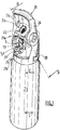
- the Figure 1 presents an embodiment of a rigid protective cover 21, commonly called a "cap”, arranged around a valve unit 1 of a gas distribution assembly according to the invention (visible on Fig. 5 ), namely a valve unit with integrated regulator, itself fixed to the neck of a gas cylinder 20, said protective cover 21 being provided with a carrying handle 25 according to the present invention.
- a rigid protective cover 21 commonly called a "cap”
- the gas cylinder 20 typically has a cylindrical steel body and a size between 10 and 150 cm, and a capacity of 0.5 to 20 liters (in water equivalent).
- the protective cover 21 makes it possible to protect the valve block 1 against shocks, which valve is of the type with integrated pressure reducer or RDI.
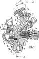
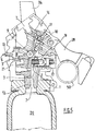
- the fixing around the valve block 1 on the neck of the gas cylinder 20 is done by screwing, via reciprocal threads carried by the internal surface of the neck of the cylinder 20, on the one hand, and by the external surface of an expansion 12 of substantially cylindrical or conical shape, located at the base of the valve body 1 and carrying the gas inlet orifice 2, as visible in Figures 2 and 5 , on the other hand.
- the protective cowling 1 comprises a cowling body forming a protective shell around an internal volume dimensioned to receive the valve unit 1, and a carrying handle 25 designed to be held in the hand by a user.
- the body of the cowling 21 is typically made of a material of polymer and / or metal type, preferably of plastic material, such as PVC, PE, PET, PP, PMMA, PU, PA, etc.
- the carrying handle 25 is formed of a rigid material, such as a polymer or a metal or metal alloy, and is carried by one or more support posts 24 mechanically connecting the cover body to the carrying handle 25.
- the carrying handle. carrying 25 is generally arranged horizontally, that is to say perpendicular or quasi-perpendicularly with respect to the vertical axis of the bottle 20 and of the cowling 21.
- the carrying handle 25 has an elongated shape, whether rectilinear or curved , typically a length of less than 20 cm, typically 6 to 15 cm.
- One or more support posts 24 are fixed to the carrying handle 25 so as to allow a user to easily transport the assembly comprising the cap 21, the valve 1 and the bottle 20 by means of the said carrying handle 25.
- the support posts 24 can be formed from a plastic material, such as the body of the cowling 21, but also from an aluminum alloy or any other metallic material. They can be attached to the handle 25 by screwing or welding, for example, or formed in one piece.
- the protective cowling 21 also has openings giving access to the valve unit 1 located in the internal volume of the cowling body.
- a first opening 22 is provided at the level of the upper part 21a, also called the upper part, of the protective cowling 21, within which is housed a pressure indicator device 7, namely here a pressure gauge, either at needle, or electronic.
- the lower part 21b, also called the lower part, of the cowling 21 is positioned around at least part of the neck of the bottle 20, as visible in Figure 1 .
- the protective cowling 21 comprises a flat surface 26 at its upper part 21a, that is to say at the top of the cowling, within which the first opening 22.
- the flat surface 26 is in fact formed. an oblique face with respect to the axis CC of the bottle 20.
- the flat surface 26 is perpendicular to the axis BB of the pressure indicating device 7, as shown diagrammatically in Figure 1 .
- the axes CC of the bottle 20 and AA of the valve block 1 are merged, that is to say coaxial.
- the protective cowling 21 comprises a second opening 27 arranged on the front or front face of the protective cowling, within which is housed the rotary handwheel 5 controlling the flow of gas passing through the valve block 1, as explained below. after in relation to Figures 2 and 3 .
- the rotary flywheel 5 is arranged around the gas outlet fitting 13 carrying the gas outlet port 6 serving to withdraw the gas stored in the cylinder 20.
- the rotary handwheel 5 can be arranged differently, that is to say. i.e. not coaxial with the gas outlet fitting 13.
- valve block 1 also comprises a filling connection 17 with an internal valve 18, (cf. Fig. 2 and 5 ), which filling connection 17 serves to introduce pressurized gas into the cylinder 20 when the latter is empty or almost empty.
- the protective cover 21 comprises, on the side of its rear face, a pivoting attachment device 28, between a fully folded position, called “rest” (shown schematically in Figure 1 ), that is to say the position adopted by the attachment device 28 when it is stored and in contact or near contact with the body of the cowling 21, and a fully unfolded position called “attachment” (not shown) , that is to say the position adopted by the hooking device 28 when it is fully extended and can be hooked to a support, such as a bed bar or the like.
- a pivoting attachment device 28 between a fully folded position, called “rest” (shown schematically in Figure 1 ), that is to say the position adopted by the attachment device 28 when it is stored and in contact or near contact with the body of the cowling 21, and a fully unfolded position called “attachment” (not shown) , that is to say the position adopted by the hooking device 28 when it is fully extended and can be hooked to a support, such as a bed bar or the like.
- the pressure indicator device 7 is fixed to the body 1 of the valve block which is located in the internal volume of the cowling 21, as visible on the figures. Figures 2 and 3 .
- Such an arrangement of the pressure indicator device 7 in the high position on the valve unit 1 and on the front of the cowling 21 makes it possible to considerably facilitate the reading of the pressure delivered by the pressure indicator device 7 and avoids reading errors.
- the axis BB of the manometer 7 and the axis AA of the valve unit 1 form an angle ⁇ between 0 and 90 °, in particular between 10 ° and 80 °, preferably between 25 ° and 70 °, typically of the order from 35 to 55 °.
- the gas distribution valve block of a gas distribution assembly comprises a valve body 1 schematically comprising an upper part forming the top of the valve block 1, and a lower part 1b forming the base of the block valve 1.
- the upper part therefore surmounts the lower part or base 1b of block 1.
- the lower part 1b of the valve block 1 comprises the fixing system 12a, like a thread, making it possible to fix the valve block 1 to the bottle 20, as already explained, as well as the gas inlet 2 through which a gas under pressure from the bottle 20, can enter the body 1 of the valve, then be then routed to the gas outlet 6 carried by the outlet connector 13 through which the gas can exit the body 1 of tap.
- the lower part 1b of the valve body 1 is shaped to come to be fixed by screwing.
- the lower part 1b comprises an expansion 12 of the body projecting downwards, of generally cylindrical or conical shape and carrying a thread 12a on its external surface capable of coming to cooperate by screwing with a complementary thread or internal thread formed in the bottle neck 20.
- a first internal gas passage 3 fluidly connects the gas inlet 2 to the gas outlet 6 carried by the outlet connection 13.
- This first internal gas passage 3 therefore axially passes through the expansion 12 of body 1 of generally cylindrical or conical shape, as shown in Figure 1 , said expansion 12 further carrying the gas inlet port 2.
- valve unit 1 also comprises a gas passage or flow control system 23 cooperating with the control member 5, namely here a rotary handwheel operable by the user, to control the passage of gas into the first internal gas passage 3, that is to say to allow or, conversely, to prevent any circulation of gas in said passage 3, in the direction going from the gas inlet port 2 to the gas outlet 6 carried by the outlet connector 13.
- a gas passage or flow control system 23 cooperating with the control member 5, namely here a rotary handwheel operable by the user, to control the passage of gas into the first internal gas passage 3, that is to say to allow or, conversely, to prevent any circulation of gas in said passage 3, in the direction going from the gas inlet port 2 to the gas outlet 6 carried by the outlet connector 13.
- the gas flow control system 23 comprises an element pierced with calibrated holes, the handwheel coming, depending on the case, either to make the calibrated hole corresponding to the desired flow rate cooperate with a fixed passage orifice, or to cause a movable passage orifice to cooperate. with the calibrated hole corresponding to the desired flow rate.
- Such an arrangement is conventional and known to those skilled in the art.
- the element pierced with calibrated orifices is a movable metal disc traversed by calibrated orifices.
- the orifices have different sizes, i.e. increasing ones, each size corresponding to a given flow rate.
- This disc is movable in rotation and driven by the flywheel 5.
- valve block also integrates, as shown in Figure 2 , a valve 4 movable in translation, one or more seals 15, such as O-rings, and at least one return spring 14.
- the valve 4 is a residual pressure valve intended to maintain a positive pressure permanently in the valve. bottle. This valve 4 operates autonomously, without any action of the handwheel.
- valve body 1 comprises a second internal gas passage 11 fluidly connected to the first internal gas passage 3, at a junction or fluidic connection site 10.
- the second internal gas passage 11 therefore forms a bifurcation or a branch of the first internal gas passage 3.
- the second internal gas passage 11 and at least the portion of the first internal gas passage 3 between the inlet port 2 and the fluidic junction site 10 convey high pressure gas coming directly from the gas cylinder 20. These passages 11, 3 are therefore subjected to high pressure, typically pressures of up to approximately 350 bar absolute.
- the pressure indicator device here a manometer 7, which is fixed to the valve body 1 at its upper end 1a, comprises a pressure tap 8, for example a channel or the like, in fluid communication with the second internal gas passage 11 so as to measure the gas pressure within said second internal gas passage 11.
- the pressure tap 8 of the pressure indicator device 7 can be fluidly connected to the second internal gas passage 11 indirectly, for example via a junction passage 16 arranged in the body 1 of the valve and connecting the pressure tap 8 of the device. pressure indicator 7 at the second internal gas passage 11, as shown in Figures 2 , 3 and 5 .
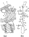
- the valve block is of the RDI type, that is to say it comprises a gas expansion system 9 arranged between the fluidic connection site 10 of the first and second internal gas passages 3, 11, and the gas outlet 6 so as to effect a reduction in the pressure of the high pressure gas coming from the bottle 20, down to a lower pressure value, for example a change from a high pressure greater than 100 bar to a low pressure less than 20 bar abs.
- an expansion system 9 comprising an expansion valve and a valve seat.
- the final pressure can be of adjustable or fixed value.
- the gas circulating in the second internal gas passage 11 is not subjected to expansion within the expansion system 9 since the junction site or fluid connection 10 between the first and second gas passages 3, 11 is located in upstream of the expansion system 9.
- the junction or fluidic connection site 10 is typically the so-called high-pressure chamber of the expansion system 9, which high-pressure chamber is then traversed by the high-pressure gas which is brought there by the first gas passage 3. Part of the high-pressure gas is then evacuated through the second gas passage 11 which then conveys it to the pressure tap 8 of the manometer 7 (or of a device for measuring autonomy) so as to make it possible to measuring the pressure of said gas.
- This architecture is essential in the context of the present invention.
- the Figure 3 makes it possible to better visualize the expansion system 9 and the high pressure chamber 10. More precisely, in addition to the pressure tap 8 and the pressure gauge 7, we see the expansion valve of elongated shape, ie stem, the valve seat, an expansion spring and an expansion piston which determines the position of the expansion valve as a function of the force of the expansion spring, high pressure and low pressure.
- valve unit also comprises an internal filter 19, as well as arranged downstream of the expansion system 9, a valve 29 and a low pressure gas outlet with isolation valve 30.
- An assembly according to the invention is particularly suitable for use in a medical environment, in particular for the distribution of any medical gas or gas mixture, in particular of the oxygen, air, N 2 O / O 2 , He / O 2 , NO type. / nitrogen or other.
Landscapes
- Engineering & Computer Science (AREA)
- Mechanical Engineering (AREA)
- General Engineering & Computer Science (AREA)
- Filling Or Discharging Of Gas Storage Vessels (AREA)
Description
L'invention porte sur un ensemble de distribution de gaz comprenant un récipient de gaz, telle une bouteille de gaz, en particulier de gaz médical, un bloc robinet à système de détente intégré fixé sur le récipient de gaz, un capotage de protection agencé autour du bloc robinet pour le protéger des chocs et des salissures et un dispositif indicateur de pression ou d'autonomie agencé de manière à permettre de diminuer les risques d'erreur de lecture de pression notamment, grâce à une souplesse accrue de positionnement des éléments soumis à haute pression.The invention relates to a gas distribution assembly comprising a gas container, such as a cylinder for gas, in particular for medical gas, a valve unit with an integrated expansion system fixed on the gas container, a protective cover arranged around of the valve unit to protect it from shocks and dirt and a pressure or autonomy indicator device arranged so as to reduce the risk of pressure reading error in particular, thanks to increased flexibility in the positioning of the elements subjected to high pressure.
Les gaz industriels et médicaux sont couramment conditionnés à haute pression dans des récipients de gaz, typiquement des bouteilles de gaz, équipés d'un bloc robinet, avec ou sans détendeur intégré, à savoir un robinet simple de type ouvert/fermé ou un robinet à détendeur intégré, encore appelé RDI, permettant de contrôler débit et pression du gaz délivré.Industrial and medical gases are commonly packaged at high pressure in gas receptacles, typically gas cylinders, equipped with a valve block, with or without an integrated pressure regulator, namely a single open / closed type valve or a valve. integrated regulator, also called RDI, to control the flow and pressure of the gas delivered.
Afin de protéger ce bloc robinet, il est courant d'agencer autour dudit bloc robinet, un capotage de protection formant coque protectrice autour du corps du robinet. Un tel capotage est couramment appelé « chapeau ». Des capotages de ce type sont décrits notamment par les documents
Classiquement, les gaz sont conditionnés à haute pression dans les récipients de gaz, telles les bouteilles de gaz, c'est-à-dire typiquement à des pressions supérieures à 100 bar absolus, en général entre 200 et 350 bar abs, voire plus.Conventionally, the gases are packaged at high pressure in gas receptacles, such as gas cylinders, that is to say typically at pressures greater than 100 bar absolute, generally between 200 and 350 bar abs, or even more.
Le gaz à haute pression sortant du récipient doit donc être détendu avant de pouvoir être utilisé, c'est-à-dire que sa pression doit être réduite jusqu'à une pression d'utilisation plus basse, appelée basse pression, par exemple une pression inférieure à 20 bar abs, voire même souvent inférieure à 10 bar abs.The high pressure gas leaving the container must therefore be relaxed before it can be used, i.e. its pressure must be reduced to a lower operating pressure, called low pressure, for example a pressure less than 20 bar abs, or even often less than 10 bar abs.
La détente du gaz peut se faire soit directement dans le bloc robinet lui-même, lorsqu'il s'agit d'un bloc robinet à détendeur intégré, encore appelé RDI, soit en aval du bloc robinet au moyen d'un dispositif détendeur de gaz.The gas can be released either directly in the valve unit itself, when it is a valve unit with integrated pressure reducer, also called RDI, or downstream of the valve unit by means of a pressure reducing device. gas.
Dans tous les cas, afin de mesurer et contrôler la pression du gaz contenu dans la bouteille sur laquelle est fixé le bloc robinet, qu'il soit avec ou sans détendeur intégré, on utilise généralement un dispositif indicateur de pression, tel un manomètre, dont la prise de pression est en communication fluidique avec le passage de gaz traversant le bloc robinet et véhiculant le gaz à haute pression provenant de la bouteille.In all cases, in order to measure and control the pressure of the gas contained in the bottle to which the valve block is attached, whether it is with or without an integrated regulator, a pressure indicator device, such as a manometer, is generally used. the pressure tap is in fluid communication with the gas passage passing through the valve block and conveying the high pressure gas coming from the bottle.
Etant donné que le gaz à haute pression pénètre dans le bloc robinet par sa partie basse, c'est-à-dire sa moitié inférieure, qui est fixée au récipient et qui porte l'orifice d'entrée de gaz du bloc robinet, le dispositif indicateur de pression, typiquement un manomètre, est aussi en général agencé en partie basse du bloc robinet, c'est-à-dire au plus près de l'entrée de la haute pression dans le corps du robinet. Ceci répond aussi à des contraintes techniques liées aux dimensions du bloc robinet.Since the high pressure gas enters the valve block through its lower part, that is to say its lower half, which is fixed to the container and which carries the gas inlet port of the valve block, the pressure indicator device, typically a manometer, is also generally arranged in the lower part of the valve block, that is to say as close as possible to the inlet of the high pressure into the valve body. This also responds to technical constraints related to the dimensions of the valve block.
De manière analogue, il est aussi possible de recourir à un dispositif indicateur d'autonomie en gaz pour déterminer le temps d'utilisation correspondant à la quantité de gaz résiduel dans le récipient de gaz équipé du bloc robinet.Similarly, it is also possible to use a gas autonomy indicator device to determine the usage time corresponding to the quantity of residual gas in the gas container equipped with the valve block.
Or, la nécessité de positionner ce dispositif indicateur de pression ou d'autonomie en gaz en partie basse du bloc robinet fait qu'il est souvent difficile ou peu aisé de lire la valeur de pression ou d'autonomie en gaz indiquée par celui-ci, ce qui conduit à des erreurs de lecture ou à une obligation pour l'utilisateur de se placer d'une certain façon par rapport à la bouteille pour rendre possible une lecture correcte de la valeur de pression ou d'autonomie donnée par le dispositif indicateur de pression ou d'autonomie.However, the need to position this pressure or gas autonomy indicator device in the lower part of the valve block makes it often difficult or difficult to read the pressure or gas autonomy value indicated by it. , which leads to reading errors or to an obligation for the user to position himself in a certain way with respect to the bottle in order to make possible a correct reading of the pressure or autonomy value given by the indicating device pressure or autonomy.
Le document
D'autres dispositifs de distribution de gaz pour bouteilles de gaz sont enseignés par
Au vu de cela, le problème qui se pose est d'améliorer le confort et/ou la facilité de lecture du dispositif indicateur de pression ou d'autonomie en gaz, de préférence un manomètre, équipant un bloc robinet de distribution de gaz, typiquement pour bouteille ou autre récipient de gaz, d'un ensemble de distribution de gaz en évitant les inconvénients susmentionnés, c'est-à-dire de proposer un ensemble de distribution de gaz avec bloc robinet de conception améliorée.In view of this, the problem that arises is to improve the comfort and / or the ease of reading of the pressure or gas autonomy indicator device, preferably a pressure gauge, fitted to a gas distribution valve unit, typically for cylinder or other gas receptacle, a gas distribution assembly avoiding the aforementioned drawbacks, that is to say to provide a gas distribution assembly with valve block of improved design.
La solution de l'invention est alors un ensemble de distribution de gaz comprenant un récipient de gaz, un bloc robinet fixé sur le récipient de gaz, ledit un bloc robinet de distribution de gaz comprenant :
- un corps de robinet comprenant une partie inférieure comprenant un système de fixation permettant de fixer le bloc robinet à un récipient de gaz, et une partie supérieure surmontant la partie inférieure, la partie inférieure du corps de robinet comprenant un orifice d'entrée de gaz par lequel un gaz peut pénétrer dans le corps de robinet,
- au moins un orifice de sortie de gaz par lequel le gaz peut ressortir du corps de robinet,
- un premier passage interne de gaz reliant fluidiquement l'orifice d'entrée de gaz à l'orifice de sortie de gaz, et
- un dispositif indicateur de pression ou d'autonomie en gaz fixé au corps de robinet, tel un manomètre,
- le corps de robinet comprend un second passage interne de gaz relié fluidiquement au premier passage interne de gaz de manière à ce que la pression gazeuse s'exerçant dans ledit second passage interne de gaz soit égale (i.e. strictement égale ou approximativement égale) à celle s'exerçant dans le premier passage interne de gaz en amont du site de raccordement fluidique des premier et deuxième passages internes de gaz, et
- le dispositif indicateur de pression ou d'autonomie en gaz est fixé au corps de robinet au niveau de son extrémité supérieure, et comprend une prise de pression en communication fluidique avec le second passage interne de gaz de manière à mesurer la pression du gaz au sein dudit second passage interne de gaz, c'est-à-dire la pression du gaz à haute pression présent dans le second passage interne de gaz, et
- le corps de robinet comprend un système de détente de gaz agencé entre le site de raccordement fluidique des premier et deuxième passages internes de gaz, et l'orifice de sortie de gaz,
- une ouverture aménagée au niveau de la partie supérieure du capotage de protection et au sein de laquelle vient se loger le dispositif indicateur de pression ou d'autonomie en gaz du corps de robinet, et
- une poignée de portage reliée au capotage par l'intermédiaire d'un ou plusieurs montants-supports, ladite poignée de portage étant agencée sur le capotage de manière à ce que le dispositif indicateur de pression ou d'autonomie en gaz soit positionné sensiblement entre la poignée de portage et le bloc robinet portant ledit dispositif indicateur de pression ou d'autonomie en gaz.
- a valve body comprising a lower part comprising a fixing system for fixing the valve unit to a gas container, and an upper part surmounting the lower part, the lower part of the valve body comprising a gas inlet orifice through which gas can enter the valve body,
- at least one gas outlet orifice through which gas can exit the valve body,
- a first internal gas passage fluidly connecting the gas inlet port to the gas outlet port, and
- a pressure or gas autonomy indicator device attached to the valve body, such as a pressure gauge,
- the valve body comprises a second internal gas passage fluidly connected to the first internal gas passage so that the gas pressure exerted in said second internal gas passage is equal (ie strictly equal or approximately equal) to that s '' exerting in the first internal gas passage upstream of the fluidic connection site of the first and second internal gas passages, and
- the pressure or gas autonomy indicator device is fixed to the valve body at its upper end, and comprises a pressure tap in fluid communication with the second internal gas passage so as to measure the pressure of the gas within said second internal gas passage, i.e. the pressure of the high pressure gas present in the second internal gas passage, and
- the valve body comprises a gas expansion system arranged between the fluidic connection site of the first and second internal gas passages, and the gas outlet orifice,
- an opening made at the upper part of the protective cowling and within which is housed the device indicating the pressure or the gas autonomy of the valve body, and
- a carrying handle connected to the cowling by means of one or more support posts, said carrying handle being arranged on the cowling so that the pressure or gas autonomy indicator device is positioned substantially between the carrying handle and the valve unit carrying said pressure or gas autonomy indicator device.
De façon générale, un ensemble de distribution de gaz conforme à la présente invention présente de nombreux avantages, outre le confort de lecture de pression pour l'utilisateur du fait de la position possible du dispositif indicateur de pression ou d'autonomie en partie haute du bloc robinet, il permet notamment de prévoir une ou des sorties de gaz à haute pression sur le haut du bloc robinet, c'est-à-dire à l'opposé de la source de gaz par rapport au système de détente éventuellement présent, mais aussi d'améliorer l'ergonomie globale du bloc robinet, ce qui tend également à diminuer les risques d'erreur de lecture de pression notamment, grâce à une souplesse accrue de positionnement des éléments soumis à haute pression, à savoir le dispositif indicateur de pression, tel un manomètre, ou d'autonomie mais aussi d'autres éléments, tels que capteur de pression, disque de rupture...In general, a gas distribution assembly in accordance with the present invention has many advantages, in addition to the pressure reading comfort for the user due to the possible position of the pressure or autonomy indicator device in the upper part of the device. valve block, it allows in particular to provide one or more high pressure gas outlets on the top of the valve block, that is to say opposite the gas source with respect to the expansion system that may be present, but also to improve the overall ergonomics of the valve unit, which also tends to reduce the risk of pressure reading error in particular, thanks to increased flexibility in the positioning of the elements subjected to high pressure, namely the pressure indicator device , such as a pressure gauge, or autonomy but also other elements, such as pressure sensor, rupture disc ...
Selon le cas, l'ensemble de distribution de gaz de l'invention peut comprendre l'une ou plusieurs des caractéristiques techniques suivantes :
- le bloc robinet comprend un système de contrôle de passage de gaz agencé sur le premier passage interne de gaz, et un organe de commande manœuvrable par un utilisateur et coopérant avec le système de contrôle de passage de gaz pour contrôler le passage de gaz dans le premier passage interne de gaz, dans le sens allant de l'orifice d'entrée de gaz à l'orifice de sortie de gaz, c'est-à-dire pour ajuster le débit du gaz délivré.
- le dispositif indicateur du contenu de la bouteille est un indicateur de pression
- le dispositif indicateur du contenu de la bouteille est un manomètre.
- le dispositif indicateur du contenu de la bouteille est un indicateur d'autonomie en gaz.
- le dispositif indicateur du contenu de la bouteille est un dispositif à aiguille ou digital indiquant une estimation de la durée d'utilisation du gaz correspondant à la quantité de gaz résiduel dans la bouteille.
- le dispositif indicateur du contenu de la bouteille est de préférence un dispositif électronique qui calcule et affiche une autonomie en gaz exprimée en unité de temps.
- le robinet est donc un robinet à détendeur intégré ou RDI.
- l'axe BB du dispositif indicateur de pression forme avec l'axe AA du corps de robinet un angle α compris entre 0 et 90°, de préférence entre 10° et 80°, de préférence encore entre 25° et 70°.
- l'orifice de sortie de gaz est porté par un raccord de sortie de gaz, situé entre les parties supérieure et inférieure du corps de robinet par exemple.
- le système de détente comprend une chambre haute pression, un clapet et un siège de clapet, et une chambre basse pression.
- le système de contrôle de passage de gaz comprend un élément mobile portant des orifices calibrés présentant des dimensions croissantes correspondant à des valeurs de débit de gaz croissantes.
- l'élément mobile du système de contrôle de passage de gaz est un disque rotatif. Ce disque rotatif est percé d'orifices calibrés.
- le volant rotatif coopère en rotation avec l'élément mobile du système de contrôle de passage de gaz pour contrôler le débit de gaz délivré par le bloc robinet.
- la portion du premier passage interne de gaz située entre l'orifice d'entrée de gaz et le site de raccordement fluidique des premier et deuxième passages internes de gaz, et le second passage interne de gaz sont conformés, c'est-à-dire aptes à et conçus pour, véhiculer du gaz à haute pression.
- le dispositif indicateur de pression est un manomètre à aiguille ou un manomètre à affichage digital, encore appelé manomètre « électronique » ou « numérique ».
- la prise de pression du dispositif indicateur de pression ou d'autonomie en gaz est en communication fluidique avec le second passage interne de gaz via un passage de jonction aménagé dans le corps du robinet.
- l'organe de commande manœuvrable par un utilisateur est un volant rotatif ou un levier pivotant, de préférence un volant rotatif.
- le volant rotatif est agencé coaxialement et autour du raccord de sortie de gaz portant l'orifice de sortie de gaz.
- le site de raccordement fluidique comprend la chambre à haute pression du système de détente. Cette chambre à haute pression est donc traversée par le gaz à haute pression, c'est-à-dire que le premier passage de gaz amène le gaz à haute pression jusqu'à ladite chambre haute pression et le deuxième passage de gaz évacue une partie du gaz à haute pression de ladite chambre et l'achemine jusqu'à la prise de pression du dispositif indicateur de pression ou d'autonomie en gaz de manière à pouvoir mesurer la pression dudit gaz. En d'autres termes, le site de raccordement fluidique (i.e. de jonction) est situé en amont du système de détente, donc de la détente elle-même, la chambre haute pression étant confondue avec le site de raccordement fluidique ou reliée à celui-ci.
- le corps du robinet est en alliage de cuivre, en laiton, en acier ou en acier inoxydable, ou en alliage d'aluminium.
- le système de fixation permettant de fixer la partie inférieure du corps de robinet à un récipient de gaz comprend un filetage aménagé sur la périphérie externe d'une expansion de forme cylindrique ou conique localisée au niveau de la partie inférieure du corps de robinet. Le filetage porté par l'expansion cylindrique ou conique vient se fixer par vissage au sein d'un filetage/taraudage réciproque aménagé au niveau de l'orifice de sortie du récipient de gaz, en particulier au niveau du col d'une bouteille de gaz.
- le corps du robinet comprend en outre un raccord de remplissage comprenant un orifice de remplissage, de préférence avec un clapet interne anti-retour, permettant d'introduire du gaz à haute pression dans le récipient de gaz équipé dudit corps de robinet, par exemple lorsque celui-ci est vide, c'est-à-dire qu'il ne contient pas ou plus de gaz, ou quasiment vide, c'est-à-dire qu'il en contient encore un peu.
- le récipient de gaz est une bouteille de gaz, encore appelée bonbonne, obus ou cylindre.
- l'ouverture aménagée au niveau de la partie supérieure du capotage de protection est aménagée au travers de la paroi du capotage.
- le capotage de protection comprend une surface plane au niveau sa partie supérieure, l'ouverture comprenant le dispositif indicateur de pression ou d'autonomie en gaz étant aménagée dans ladite surface plane.
- la surface plane forme une face oblique par rapport à l'axe vertical du capotage.
- le capotage est en matériau polymère, par exemple en plastique, en composite, ou en métal ou alliage métallique, par exemple en acier, en fonte, en aluminium ou en un alliage d'aluminium.
- le capotage est en matériau plastique, tel que le PVC, le PE, le PET, le PP, le PMMA, le PU, le PA.... Il est à noter que le matériau plastique peut être chargé ou renforcé, c'est-à-dire additionné de fibres par exemple.
- le capotage de protection comprend en outre un dispositif d'accrochage, de préférence un dispositif d'accrochage pivotant, permettant d'accrocher l'ensemble à un support, en particulier un barreau de lit, à un brancard...
- la poignée de portage et/ou le ou les montants-supports sont formés d'un matériau rigide choisi parmi les polymères et les métaux ou alliages métalliques.
- la poignée de portage est globalement longiforme. Typiquement, sa longueur est comprise
entre 5 et 20 cm, de préférence entre 6 et 15 cm. - la poignée de portage surmonte le corps de capotage.
- la poignée de portage est horizontale ou quasi-horizontale et perpendiculaire à l'axe vertical du capotage (i.e. l'axe du capotage correspond à l'axe du robinet et/ou de la bouteille).
- la bouteille de gaz a une taille comprise entre 10 et 150 cm.
- la bouteille de gaz contient de 0,5 à 20 litres (contenance en équivalent eau).
- la bouteille de gaz a un corps cylindrique creux et comprend un col portant un orifice de sortie de gaz au niveau duquel est fixé le bloc robinet, de préférence par vissage.
- la bouteille de gaz contient un gaz ou mélange gazeux, de préférence un gaz ou mélange gazeux conforme aux spécifications du domaine médical (pharmacopée).
- la bouteille de gaz contient un gaz ou mélange gazeux choisi parmi l'oxygène, l'air, un mélange N2O/O2, un mélange He/O2, un mélange NO/azote ou tout autre gaz ou mélange gazeux.
- la bouteille est en acier, en un alliage d'aluminium, en matériau composite ou une combinaison de plusieurs de ces matériaux.
- la bouteille contient du gaz à une pression allant jusqu'à 350 bar environ.
- the valve unit comprises a gas passage control system arranged on the first internal gas passage, and a control member operable by a user and cooperating with the gas passage control system to control the passage of gas in the first internal gas passage, in the direction going from the gas inlet orifice to the gas outlet orifice, that is to say to adjust the flow rate of the gas delivered.
- the device indicating the contents of the bottle is a pressure indicator
- the device indicating the contents of the bottle is a pressure gauge.
- the device indicating the contents of the bottle is a gas autonomy indicator.
- the device indicating the contents of the bottle is a needle or digital device indicating an estimate of the duration of use of the gas corresponding to the quantity of residual gas in the bottle.
- the device indicating the contents of the bottle is preferably an electronic device which calculates and displays a gas autonomy expressed in units of time.
- the valve is therefore a valve with built-in regulator or RDI.
- the axis BB of the pressure indicator device forms with the axis AA of the valve body an angle α of between 0 and 90 °, preferably between 10 ° and 80 °, more preferably between 25 ° and 70 °.
- the gas outlet orifice is carried by a gas outlet connector, located between the upper and lower parts of the valve body for example.
- the expansion system comprises a high pressure chamber, a valve and valve seat, and a low pressure chamber.
- the gas passage control system comprises a movable element carrying calibrated orifices having increasing dimensions corresponding to increasing gas flow values.
- the movable element of the gas passage control system is a rotating disc. This rotating disc is pierced with calibrated orifices.
- the rotary handwheel cooperates in rotation with the movable element of the gas passage control system to control the flow of gas delivered by the valve unit.
- the portion of the first internal gas passage located between the gas inlet port and the fluid connection site of the first and second internal gas passages, and the second internal gas passage are shaped, i.e. suitable for and designed for conveying gas at high pressure.
- the pressure indicating device is a needle pressure gauge or a digital display pressure gauge, also called an “electronic” or “digital” pressure gauge.
- the pressure tap of the pressure or gas autonomy indicator device is in fluid communication with the second internal gas passage via a junction passage arranged in the body of the valve.
- the control member operable by a user is a rotary steering wheel or a pivoting lever, preferably a rotary steering wheel.
- the rotary flywheel is arranged coaxially and around the gas outlet fitting carrying the gas outlet orifice.
- the fluidic connection site includes the high pressure chamber of the expansion system. This high pressure chamber is therefore crossed by the high pressure gas, that is to say that the first gas passage brings the high pressure gas to said high pressure chamber and the second gas passage evacuates a part. gas at high pressure from said chamber and conveys it to the pressure tap of the pressure or gas autonomy indicator device so as to be able to measure the pressure of said gas. In other words, the fluidic connection site (ie junction) is located upstream of the expansion system, therefore of the expansion itself, the high pressure chamber being coincident with the fluidic connection site or connected to it. this.
- The faucet body is made of copper alloy, brass, steel or stainless steel, or aluminum alloy.
- the fastening system for securing the lower portion of the valve body to a gas container comprises a thread provided on the outer periphery of a cylindrical or conical shaped expansion located at the lower portion of the valve body. The thread carried by the cylindrical or conical expansion is fixed by screwing within a reciprocal thread / tapping provided at the level of the outlet of the gas container, in particular at the level of the neck of a gas cylinder. .
- the valve body further comprises a filling connection comprising a filling orifice, preferably with an internal non-return valve, allowing gas to be introduced at high pressure into the gas container equipped with said valve body, for example when it is empty, that is to say that it contains no or more gas, or almost empty, that is to say that it still contains a little.
- the gas container is a gas cylinder, also called a carboy, shell or cylinder.
- the opening made at the level of the upper part of the protective cowling is made through the wall of the cowling.
- the protective cowling comprises a flat surface at its upper part, the opening comprising the pressure or gas autonomy indicator device being arranged in said flat surface.
- the flat surface forms an oblique face with respect to the vertical axis of the cowling.
- the cowling is made of polymer material, for example plastic, composite, or metal or metal alloy, for example steel, cast iron, aluminum or an aluminum alloy.
- the cowling is made of plastic material, such as PVC, PE, PET, PP, PMMA, PU, PA .... It should be noted that the plastic material can be loaded or reinforced, it is that is to say added with fibers for example.
- the protective cover further comprises a hooking device, preferably a pivoting hooking device, allowing the assembly to be hooked to a support, in particular a bed bar, to a stretcher ...
- the carrying handle and / or the support post (s) are formed from a rigid material chosen from polymers and metals or metal alloys.
- the carrying handle is generally elongated. Typically, its length is between 5 and 20 cm, preferably between 6 and 15 cm.
- the carrying handle surmounts the cover body.
- the carrying handle is horizontal or quasi-horizontal and perpendicular to the vertical axis of the cowling (ie the axis of the cowling corresponds to the axis of the valve and / or of the bottle).
- the gas cylinder has a size between 10 and 150 cm.
- the gas cylinder contains 0.5 to 20 liters (water equivalent capacity).
- the gas cylinder has a hollow cylindrical body and comprises a neck carrying a gas outlet orifice at which the valve block is fixed, preferably by screwing.
- the gas cylinder contains a gas or gas mixture, preferably a gas or gas mixture conforming to the specifications of the medical field (pharmacopoeia).
- the gas cylinder contains a gas or gas mixture chosen from oxygen, air, an N 2 O / O 2 mixture, a He / O 2 mixture, an NO / nitrogen mixture or any other gas or gas mixture.
- the cylinder is made of steel, an aluminum alloy, a composite material or a combination of several of these materials.
- the cylinder contains gas at a pressure of up to approximately 350 bar.
L'invention concerne en outre une utilisation d'un ensemble de distribution de gaz selon l'invention pour distribuer un gaz ou mélange gazeux, de préférence un gaz ou mélange gazeux médical.The invention further relates to a use of a gas distribution assembly according to the invention for distributing a gas or gas mixture, preferably a medical gas or gas mixture.
De préférence, le gaz ou mélange gazeux est choisi parmi l'oxygène, air, N2O/O2, He/O2, NO/azotePreferably, the gas or gas mixture is chosen from oxygen, air, N 2 O / O 2 , He / O 2 , NO / nitrogen
L'invention va maintenant être mieux comprise grâce à la description détaillée suivante, faite à titre illustratif mais non limitatif, en référence aux figures annexées parmi lesquelles :
- la
Figure 1 représente un mode de réalisation d'un ensemble bouteille/bloc robinet/capotage selon l'invention, et - les
Figures 2 et 3 représentent des vues en coupe du bloc robinet de l'ensemble de laFigure 1 , - la
Figure 4 schématise le principe de fonctionnement du bloc robinet de l'ensemble de laFigure 1 , et - la
Figure 5 représente une vue en coupe du bloc robinet de laFigure 2 agencé dans un capotage de protection.
- the
Figure 1 represents an embodiment of a bottle / valve unit / cowling assembly according to the invention, and - the
Figures 2 and3 represent sectional views of the valve block of the assembly of theFigure 1 , - the
Figure 4 schematizes the operating principle of the valve block of the entireFigure 1 , and - the
Figure 5 shows a sectional view of the valve block of theFigure 2 arranged in a protective cover.
La
La bouteille de gaz 20 a typiquement un corps cylindrique en acier et une taille entre 10 et 150 cm, et une contenance de 0,5 à 20 litres (en équivalent eau).The
Le capotage de protection 21 permet de protéger le bloc robinet 1 contre les chocs, lequel robinet est du type avec détendeur intégré ou RDI.The protective cover 21 makes it possible to protect the
La fixation autour du bloc de robinet 1 sur le col de la bouteille de gaz 20 se fait par vissage, via des filetages réciproques portés par la surface interne du col de la bouteille 20, d'une part, et par la surface externe d'une expansion 12 de forme sensiblement cylindrique ou conique, située à la base du corps 1 de robinet et portant l'orifice d'entrée de gaz 2, comme visible en
Plus précisément, le capotage de protection 1 comprend un corps de capotage formant une coque protectrice autour d'un volume interne dimensionné pour recevoir le bloc robinet 1, et une poignée de portage 25 conçue pour être prise en main par un utilisateur.More precisely, the
Le corps du capotage 21 est typiquement en un matériau de type polymère et/ou métal, préférentiellement en matériau plastique, tel que PVC, PE, PET, PP, PMMA, PU, PA...The body of the cowling 21 is typically made of a material of polymer and / or metal type, preferably of plastic material, such as PVC, PE, PET, PP, PMMA, PU, PA, etc.
La poignée de portage 25 est formée d'un matériau rigide, tel un polymère ou un métal ou alliage métallique, et est portée par un ou plusieurs montants-supports 24 reliant mécaniquement le corps de capotage à la poignée de portage 25. La poignée de portage 25 est généralement agencée horizontalement, c'est-à-dire perpendiculairement ou quasiperpendiculairement par rapport à l'axe vertical de la bouteille 20 et du capotage 21. La poignée de portage 25 a une forme longiligne, qu'elle soit rectiligne ou incurvée, typiquement une longueur inférieure à 20 cm, typiquement de 6 à 15 cm.The carrying
Un ou des montants-supports 24 sont fixés à la poignée de portage 25 de manière à permettre à un utilisateur de transporter facilement l'ensemble comprenant le chapeau 21, le robinet 1 et la bouteille 20 au moyen de ladite poignée de portage 25.One or more support posts 24 are fixed to the carrying
Les montants-supports 24 peuvent être formés d'un matériau plastique, comme le corps du capotage 21, mais aussi en alliage d'aluminium ou tout autre matériau métallique. Ils peuvent être fixés à la poignée 25 par vissage ou soudage, par exemple, ou formés d'une seule pièce.The support posts 24 can be formed from a plastic material, such as the body of the cowling 21, but also from an aluminum alloy or any other metallic material. They can be attached to the
Le capotage de protection 21 présente par ailleurs des ouvertures donnant accès au bloc robinet 1 situé dans le volume interne du corps de capotage.The protective cowling 21 also has openings giving access to the
En particulier, une première ouverture 22 est aménagée au niveau de la partie supérieure 21a, encore appelée partie haute, du capotage de protection 21, au sein de laquelle vient se loger un dispositif indicateur de pression 7, à savoir ici un manomètre, soit à aiguille, soit électronique. La partie inférieure 21b, encore appelée partie basse, du capotage 21 vient se positionner autour d'au moins une partie du col de la bouteille 20, comme visible en
Plus précisément, le capotage de protection 21 comprend une surface plane 26 au niveau sa partie supérieure 21a, c'est-à-dire en haut du capotage, au sein de laquelle est aménagée la première ouverture 22. La surface plane 26 constitue en fait une face oblique par rapport à l'axe CC de la bouteille 20. De préférence, la surface plane 26 est perpendiculaire à l'axe BB du dispositif indicateur de pression 7, comme schématisé en
Par ailleurs, le capotage de protection 21 comprend une deuxième ouverture 27 aménagée en façade ou face avant du capotage de protection, au sein de laquelle vient se loger le volant rotatif 5 contrôlant le débit du gaz traversant le bloc robinet 1, comme expliqué ci-après en relation avec les
Dans le mode de réalisation de la
Par ailleurs, le bloc robinet 1 comprend également un raccord de remplissage 17 avec un clapet interne 18, (cf.
En outre, afin de permettre l'accroche ou l'arrimage de l'ensemble bouteille/bloc robinet/capotage à un support, tel un barreau de lit d'hôpital ou de brancard, le capotage de protection 21 comprend, du côté de sa face arrière, un dispositif d'accrochage 28 pivotant, entre une position totalement repliée, dite « de repos » (schématisé en
Dans tous les cas, le dispositif indicateur de pression 7 est fixé au corps 1 du bloc robinet qui est situé dans le volume interne du capotage 21, comme visible sur les
De préférence, comme illustré en
Comme détaillé en
La partie inférieure 1b du bloc robinet 1 comprend le système de fixation 12a, tel un filetage, permettant de fixer le bloc robinet 1 à la bouteille 20, comme déjà expliqué, ainsi que l'orifice d'entrée de gaz 2 par lequel un gaz sous pression provenant de la bouteille 20, peut pénétrer dans le corps 1 de robinet, puis y être ensuite acheminé jusqu'à l'orifice de sortie 6 de gaz porté par le raccord de sortie 13 par lequel le gaz peut ressortir du corps 1 de robinet.The lower part 1b of the
Comme déjà expliqué, la partie inférieure 1b du corps 1 de robinet est conformée pour venir se fixer par vissage. Pour ce faire, la partie inférieure 1b comporte une expansion 12 du corps se projetant vers le bas, de forme globalement cylindrique ou conique et portant un filetage 12a sur sa surface externe apte à venir coopérer par vissage avec un filetage ou taraudage complémentaire aménagé dans le col de la bouteille 20.As already explained, the lower part 1b of the
Un premier passage interne de gaz 3 relie fluidiquement l'orifice d'entrée de gaz 2 à l'orifice de sortie 6 de gaz porté par le raccord de sortie 13. Ce premier passage interne de gaz 3 traverse donc axialement l'expansion 12 de corps 1 de forme globalement cylindrique ou conique, comme montré en
Par ailleurs, le bloc robinet 1 comprend aussi un système de contrôle de passage ou de débit de gaz 23 coopérant avec l'organe de commande 5, à savoir ici un volant rotatif manœuvrable par l'utilisateur, pour contrôler le passage de gaz dans le premier passage interne de gaz 3, c'est-à-dire pour autoriser ou, à l'inverse, empêcher toute circulation du gaz dans ledit passage 3, dans le sens allant de l'orifice d'entrée de gaz 2 à l'orifice de sortie de gaz 6 portée par le raccord de sortie 13.Furthermore, the
Le système de contrôle de débit de gaz 23 comprend un élément perçé de trous calibrés, le volant venant, selon les cas, soit faire coopérer le trou calibré correspondant au débit souhaité avec un orifice de passage fixe, soit faire coopérer un orifice de passage mobile avec le trou calibré correspondant au débit souhaité. Un tel agencement est classique et connu de l'homme du métier.The gas
Ainsi, selon le mode de réalisation présenté ici, l'élément perçé d'orifices calibrés est un disque métallique mobile traversé par des orifices calibrés. Les orifices ont des calibres différents, i.e. croissants, chaque calibre correspondant à une valeur de débit donnée. Ce disque est mobile en rotation et entraîné par le volant 5.Thus, according to the embodiment presented here, the element pierced with calibrated orifices is a movable metal disc traversed by calibrated orifices. The orifices have different sizes, i.e. increasing ones, each size corresponding to a given flow rate. This disc is movable in rotation and driven by the
Il n'y a pas de clapet dans le système de contrôle de passage dans le mode de réalisation présenté sur les Figures. Toutefois, selon d'autres conceptions plus classiques intégrant une fonction ouvert/fermé dans la partie haute pression du bloc robinet, on peut prévoir que le volant 5 commande aussi cette fonction ouvert/fermé. Dans ce cas, intégrer un clapet d'ouverture/fermeture venant faire l'étanchéité sur un siège en position fermée peut s'avérer nécessaire.There is no valve in the passage control system in the embodiment shown in the Figures. However, according to other more classic designs integrating an open / closed function in the high pressure part of the valve unit, provision can be made for the
En outre, le bloc robinet intègre aussi, comme illustré en
Conformément à la présente invention et illustré en
Le second passage interne de gaz 11 forme donc une bifurcation ou un embranchement du premier passage interne de gaz 3.The second
Le second passage interne de gaz 11 et au moins la portion du premier passage interne de gaz 3 comprise entre l'orifice d'entrée 2 et le site de jonction fluidique 10 véhiculent du gaz à haute pression provenant directement de la bouteille de gaz 20. Ces passages 11, 3 sont donc soumis à haute pression, typiquement des pressions allant jusqu'à 350 bar absolus environ.The second
Par ailleurs, le dispositif indicateur de pression, ici un manomètre 7, qui est fixé au corps de robinet 1 au niveau de son extrémité supérieure 1a, comprend une prise de pression 8, par exemple un canal ou analogue, en communication fluidique avec le second passage interne de gaz 11 de manière à mesurer la pression du gaz au sein dudit second passage interne de gaz 11.Furthermore, the pressure indicator device, here a
La prise de pression 8 du dispositif indicateur de pression 7 peut être reliée fluidiquement au second passage interne de gaz 11 de manière indirecte, par exemple via un passage de jonction 16 aménagé dans le corps 1 du robinet et reliant la prise de pression 8 du dispositif indicateur de pression 7 au second passage interne de gaz 11, comme illustré en
Dans le mode de réalisation des
A cette fin, de manière classique, on prévoit un système de détente 9 comprenant un clapet de détente et un siège de clapet. La pression finale peut être de valeur réglable ou fixe.To this end, conventionally, an
Comme visible sur les
Le site de jonction ou de raccordement fluidique 10 est typiquement la chambre dite à haute pression du système de détente 9, laquelle chambre à haute pression est alors traversée par le gaz à haute pression qui y est amené par le premier passage 3 de gaz. Une partie du gaz à haute pression est ensuite évacué par le deuxième passage de gaz 11 qui l'achemine alors jusqu'à la prise de pression 8 du manomètre 7 (ou d'un dispositif de mesure d'autonomie) de manière à permettre de mesurer la pression dudit gaz. Cette architecture est primordiale dans le cadre de la présente invention.The junction or
La
Tous ces éléments sont visibles également sur la
On y voit aussi que le bloc robinet comprend également un filtre interne 19, ainsi qu'agencées en aval du système de détente 9, une soupape 29 et une sortie de gaz à basse pression avec vanne d'isolement 30.It can also be seen that the valve unit also comprises an
Un ensemble selon l'invention est particulièrement adapté pour un usage en milieu médical, en particulier à la distribution de tout gaz ou mélange gazeux médical, en particulier de type oxygène, air, N2O/O2, He/O2, NO/azote ou autre.An assembly according to the invention is particularly suitable for use in a medical environment, in particular for the distribution of any medical gas or gas mixture, in particular of the oxygen, air, N 2 O / O 2 , He / O 2 , NO type. / nitrogen or other.
Claims (14)
- Gas distribution assembly (1, 20, 21) comprising a gas container (20) and a valve unit (1) fixed to the gas container (20), said gas distribution valve unit comprising:- a valve body (1) comprising a lower part (1b) comprising a fixing system (12, 12a) allowing the valve unit to be fixed to a gas container (20), and an upper part (1a) surmounting the lower part (1b), the lower part (1b) of the valve body (1) comprising a gas inlet orifice (2) via which a gas can enter the valve body (1),- a gas outlet orifice (6) via which the gas can reemerge from the valve body (1),- a first internal gas passage (3) fluidically connecting the gas inlet orifice (2) to the gas outlet orifice (6), and- a gas autonomy or pressure indicating device (7) fixed to the valve body (1),and wherein:- the valve body (1) comprises a second internal gas passage (11) fluidically connected (10) to the first internal gas passage (3) so that the gas pressure applied in said second internal gas passage (11) is equal to that applied in the first internal gas passage (3) upstream of the site of fluidic connection (10) of the first and second internal gas passages (3, 11),- the autonomy or pressure indicating device (7) is fixed to the valve body (1) at its upper end (1a) and comprises a pressure tapping (8) in fluidic communication with the second internal gas passage (11) so as to measure the pressure of the gas within said second internal gas passage (11), and- the valve body (1) comprises a gas expansion system (9) arranged between the site of fluidic connection (10) of the first and second internal gas passages (3, 11) and the gas outlet orifice (6),characterized in that it comprises a protective cowling (21) arranged around said valve unit (1), the protective cowling (21) comprising:- an opening (22) formed level with the upper part (21a) of the protective cowling (21) and within which the gas autonomy or pressure indicating device (7) of the valve unit (1) becomes housed, and- a carry handle (25) connected to the cowling (21) via one or more support uprights (24), said carry handle being arranged on the cowling (21) in such a way that the gas autonomy or pressure indicating device (7) is positioned substantially between the carry handle (25) and the valve unit (24) bearing said gas autonomy or pressure indicating device (7).
- Gas distribution assembly according to Claim 1, characterized in that the pressure indicating device (7) is a dial-type pressure gauge or a pressure gauge with a digital display.
- Gas distribution assembly to Claim 1, characterized in that the autonomy indicating device (7) is a dial-type or digital device.
- Gas distribution assembly according to one of Claims 1 and 3, characterized in that the autonomy indicating device (7) is an electronic device which calculates and displays a gas autonomy expressed in time units.
- Gas distribution assembly according to one of the preceding claims, characterized in that the valve unit (1) comprises a gas flow rate control system (23) arranged on the first internal gas passage (3) and a control member (5) operable by a user and collaborating with the gas passage control system (23) to control the passage of gas in the first internal gas passage (3), in the direction running from the gas inlet orifice (2) to the gas outlet orifice (6).
- Gas distribution assembly according to one of the preceding claims, characterized in that the pressure tapping (8) of the gas autonomy or pressure indicating device (7) is in fluidic communication with the second internal gas passage (11) via a connecting passage (16) formed in the body of the valve (1).
- Gas distribution assembly according to one of the preceding claims, characterized in that the axis (BB) of the gas autonomy or pressure indicating device (7) forms, with the axis (AA) of the valve body (1), an angle (α) comprised between 0° and 90°.
- Gas distribution assembly according to one of the preceding claims, characterized in that the axis (BB) of the gas autonomy or pressure indicating device (7) forms, with the axis (AA) of the valve body (1), an angle (α) comprised between 10° and 80°.
- Gas distribution assembly according to one of the preceding claims, characterized in that the site of fluidic connection (10) comprises the high-pressure chamber of the expansion system (9).
- Gas distribution assembly according to one of Claims 5, or 6 to 9, when these latter are dependent on Claim 5, characterized in that the control member (5) operable by a user is a rotary handwheel.
- Gas distribution assembly according to one of the preceding claims, characterized in that the protective cowling (21) further comprises a pivoting hang-up device (28) so that the assembly can be hung on a support.
- Gas distribution assembly according to one of Claims 10 and 11, when the latter is dependent on Claim 10, characterized in that a protective cowling (21) comprises a second opening (27) formed on the façade of the protective cowling (21), and in which the rotary handwheel (5) controlling the flow rate of gas passing through the valve unit (1) becomes housed.
- Use of a gas distribution assembly according to one of Claims 1 to 12 for distributing a gas or gaseous mixture.
- Use according to Claim 13, characterized in that the gas or the gaseous mixture is chosen from oxygen, air, N2O/O2, He/O2, NO/nitrogen.
Applications Claiming Priority (2)
| Application Number | Priority Date | Filing Date | Title |
|---|---|---|---|
| FR1452041A FR3018580B1 (en) | 2014-03-12 | 2014-03-12 | BLOCK TAP FOR GAS CONTAINER WITH HIGH PRESSURE PRESSURE INDICATOR OR AUTONOMY DEVICE |
| PCT/FR2015/050525 WO2015136190A1 (en) | 2014-03-12 | 2015-03-04 | Valve unit for gas container with a pressure-indicating or autonomy-indicating device near the top |
Publications (2)
| Publication Number | Publication Date |
|---|---|
| EP3117136A1 EP3117136A1 (en) | 2017-01-18 |
| EP3117136B1 true EP3117136B1 (en) | 2021-06-09 |
Family
ID=51168037
Family Applications (1)
| Application Number | Title | Priority Date | Filing Date |
|---|---|---|---|
| EP15714564.0A Active EP3117136B1 (en) | 2014-03-12 | 2015-03-04 | Valve unit for gas container with a pressure-indicating or autonomy-indicating device near the top |
Country Status (8)
| Country | Link |
|---|---|
| US (1) | US20170114961A1 (en) |
| EP (1) | EP3117136B1 (en) |
| CN (1) | CN106104140B (en) |
| AU (1) | AU2015228706A1 (en) |
| CA (1) | CA2942473A1 (en) |
| ES (1) | ES2886440T3 (en) |
| FR (1) | FR3018580B1 (en) |
| WO (1) | WO2015136190A1 (en) |
Families Citing this family (15)
| Publication number | Priority date | Publication date | Assignee | Title |
|---|---|---|---|---|
| FR3045775B1 (en) * | 2015-12-18 | 2018-07-06 | Engie | METHOD AND SYSTEM FOR CALCULATING IN REAL-TIME THE PERIOD OF AUTONOMY OF AN UN-REFRIGERATED TANK CONTAINING LNG |
| FR3050053B1 (en) * | 2016-04-06 | 2018-05-04 | L'air Liquide, Societe Anonyme Pour L'etude Et L'exploitation Des Procedes Georges Claude | METHOD OF CALCULATING THE AUTONOMY OF A GAS DISTRIBUTION SET |
| FR3066804A1 (en) * | 2017-05-24 | 2018-11-30 | L'air Liquide, Societe Anonyme Pour L'etude Et L'exploitation Des Procedes Georges Claude | INTEGRATED HOLDER VALVE AND MANUAL CLOSURE VALVE FOR GAS CONTAINER |
| FR3067094B1 (en) * | 2017-06-01 | 2020-08-14 | L'air Liquide Sa Pour L'etude Et L'exploitation Des Procedes Georges Claude | TAP, STORAGE AND FILLING STATION |
| FR3067095B1 (en) * | 2017-06-01 | 2020-08-14 | L'air Liquide Sa Pour L'etude Et L'exploitation Des Procedes Georges Claude | TAP, STORAGE AND FILLING STATION |
| FR3067788A1 (en) * | 2017-06-16 | 2018-12-21 | L'air Liquide, Societe Anonyme Pour L'etude Et L'exploitation Des Procedes Georges Claude | COVERING FOR A GAS CONTAINER CARRYING AN ORDERING MEMBER OF THE INSULATION VALVE OF AN INTEGRATED REGULATOR VALVE |
| FR3093781B1 (en) * | 2019-03-12 | 2021-02-12 | Air Liquide | Valve, pressurized fluid container and methods of filling and withdrawing. |
| FR3094447B1 (en) | 2019-03-25 | 2021-06-25 | Air Liquide | Electronic device for gas container |
| FR3097615B1 (en) | 2019-06-21 | 2021-05-28 | Air Liquide | Gas container with display of possible flow rates and corresponding backup times |
| IT201900015231A1 (en) * | 2019-08-29 | 2021-03-01 | Cavagna Group Spa | VALVE WITH INTEGRATED SENSOR |
| FR3106189B1 (en) | 2020-01-14 | 2021-12-10 | Air Liquide | Gas container with display of the flow rate and the corresponding autonomy |
| FR3113714B1 (en) * | 2020-09-01 | 2022-12-09 | Lair Liquide Sa Pour L’Etude Et Lexploitation Des Procedes Georges Claude | Brass gas valve with nickel plated outlet fittings |
| IT202100032201A1 (en) * | 2021-12-22 | 2023-06-22 | Cavagna Group Spa | PROTECTIVE DEVICE FOR PRESSURE VESSELS |
| EP4555250A1 (en) | 2022-07-13 | 2025-05-21 | Praxair Technology, Inc. | Protective shroud for a valve integrated pressure regulator (vipr) |
| FR3154480B1 (en) | 2023-10-19 | 2025-12-26 | Air Liquide | Fluid container equipped with an electronically controlled dispensing valve held in place by a protective cover |
Family Cites Families (15)
| Publication number | Priority date | Publication date | Assignee | Title |
|---|---|---|---|---|
| FR2706016B1 (en) | 1993-06-03 | 1995-07-28 | France Prod Oxygenes Co | Gas bottle cap. |
| FR2706051B1 (en) * | 1993-06-03 | 1995-07-28 | Taema | Gas distribution control assembly and gas cylinder equipped with such an assembly. |
| US5520214A (en) * | 1994-09-12 | 1996-05-28 | Western/Scott Fetzer Company | Regulator and fill valve |
| FR2807820B1 (en) | 2000-04-17 | 2002-06-14 | Air Liquide Sante Int | GAS BOTTLE WITH PROTECTIVE COVERS FOR USE IN THE MEDICAL FIELD |
| DE10057469C2 (en) | 2000-11-20 | 2003-04-17 | Messer Griesheim Gmbh | Protective cap for compressed gas cylinders with a holding rail |
| US6871802B2 (en) * | 2003-02-27 | 2005-03-29 | Fike Corporation | Self-modulating inert gas fire suppression system |
| FR2859289B1 (en) * | 2003-09-03 | 2006-02-17 | Taema | INTEGRATED VALVATOR-VALVE WITH MEANS FOR LOCKING THE ACTUATOR |
| US20080035221A1 (en) * | 2004-07-21 | 2008-02-14 | African Oxygen Limited | Multifunctional Valve Unit |
| US20090272443A1 (en) * | 2008-05-02 | 2009-11-05 | Chi Ping Lee | Portable device for supplying compressed CO2 from a pressure vessel to a pneumatic tool |
| EP2116332B1 (en) * | 2008-05-05 | 2011-08-17 | Fever Industrial Co. Ltd. | Portable device for supplying compressed CO2 from a pressure vessel to a pneumatic tool |
| US8550114B2 (en) * | 2010-10-04 | 2013-10-08 | Wilton Cahn Levine | Time remaining display assembly |
| EP2586481A1 (en) | 2011-10-27 | 2013-05-01 | Linde Aktiengesellschaft | Cover for a valve cap of a gas cylinder |
| US9816642B2 (en) * | 2012-11-09 | 2017-11-14 | Praxair Technology, Inc. | Method and apparatus for controlling gas flow from cylinders |
| US9273799B2 (en) * | 2012-11-09 | 2016-03-01 | Praxair Technology, Inc. | Method and apparatus for controlling gas flow from cylinders |
| FR3018583B1 (en) * | 2014-03-12 | 2017-01-27 | Air Liquide | PROTECTIVE COVER FOR GAS BOTTLE WITH ELECTRONIC DISPLAY SCREEN IN HIGH POSITION |
-
2014
- 2014-03-12 FR FR1452041A patent/FR3018580B1/en not_active Expired - Fee Related
-
2015
- 2015-03-04 CN CN201580012162.XA patent/CN106104140B/en active Active
- 2015-03-04 WO PCT/FR2015/050525 patent/WO2015136190A1/en not_active Ceased
- 2015-03-04 EP EP15714564.0A patent/EP3117136B1/en active Active
- 2015-03-04 CA CA2942473A patent/CA2942473A1/en not_active Abandoned
- 2015-03-04 AU AU2015228706A patent/AU2015228706A1/en not_active Abandoned
- 2015-03-04 US US15/125,298 patent/US20170114961A1/en not_active Abandoned
- 2015-03-04 ES ES15714564T patent/ES2886440T3/en active Active
Non-Patent Citations (1)
| Title |
|---|
| None * |
Also Published As
| Publication number | Publication date |
|---|---|
| FR3018580A1 (en) | 2015-09-18 |
| US20170114961A1 (en) | 2017-04-27 |
| FR3018580B1 (en) | 2018-11-02 |
| CN106104140B (en) | 2018-10-02 |
| EP3117136A1 (en) | 2017-01-18 |
| WO2015136190A1 (en) | 2015-09-17 |
| CA2942473A1 (en) | 2015-09-17 |
| CN106104140A (en) | 2016-11-09 |
| ES2886440T3 (en) | 2021-12-20 |
| AU2015228706A1 (en) | 2016-10-20 |
Similar Documents
| Publication | Publication Date | Title |
|---|---|---|
| EP3117136B1 (en) | Valve unit for gas container with a pressure-indicating or autonomy-indicating device near the top | |
| EP3643958B1 (en) | Assembly comprising a protective cover and a gas cylinder with a device for indicating the pressure or autonomy in raised position | |
| EP3006808B1 (en) | Protective hood with pivoting attachment system for a gas cylinder | |
| CA2884483A1 (en) | Gas distribution assembly with a rotating control mechanism protected with a raised edge equipped with a viewing window | |
| EP3002498B1 (en) | Gas container with valve block provided with a touch screen for displaying information | |
| EP2918891B1 (en) | Hood with protective flange for the rotary control member of a gas-cylinder valve block | |
| EP1421305B1 (en) | Fluid flow control cock fitted with a lever having several stable positions | |
| LU88377A1 (en) | Bi-directional valve for a valve of a cylinder of compressed or liquefied gas and valve provided with such a valve | |
| WO2013127895A1 (en) | Tap for a gas cylinder having a visual pressure indicator | |
| EP3260760B1 (en) | Protective hood with pivoting attachment system having a halting abutment for a gas cylinder | |
| FR3042584A1 (en) | RDI GAS DISTRIBUTION BLOCK WITH AGENCY INDICATOR DEVICE IN THE CENTER OF THE WORKING WHEEL | |
| EP2937620B1 (en) | Protective cap for a gas bottle | |
| EP4542103A1 (en) | Fluid container provided with a dispensing tap with an electronic device held by a protective cover | |
| FR3052845A1 (en) | GUARD COVERAGE FOR OPEN-COVERED GAS CONTAINER WITH REMOVABLE WALL | |
| FR3052848A1 (en) | MULTI-PART PROTECTION COVER FOR GAS BOTTLE | |
| FR3067788A1 (en) | COVERING FOR A GAS CONTAINER CARRYING AN ORDERING MEMBER OF THE INSULATION VALVE OF AN INTEGRATED REGULATOR VALVE | |
| FR3113714A1 (en) | Brass gas valve with nickel plated outlet fittings | |
| FR3082914A1 (en) | TAP FOR GAS CONTAINER COMPRISING A MANOMETER PROTECTED BY A CRADLE PIECE |
Legal Events
| Date | Code | Title | Description |
|---|---|---|---|
| STAA | Information on the status of an ep patent application or granted ep patent |
Free format text: STATUS: THE INTERNATIONAL PUBLICATION HAS BEEN MADE |
|
| PUAI | Public reference made under article 153(3) epc to a published international application that has entered the european phase |
Free format text: ORIGINAL CODE: 0009012 |
|
| STAA | Information on the status of an ep patent application or granted ep patent |
Free format text: STATUS: REQUEST FOR EXAMINATION WAS MADE |
|
| 17P | Request for examination filed |
Effective date: 20161012 |
|
| AK | Designated contracting states |
Kind code of ref document: A1 Designated state(s): AL AT BE BG CH CY CZ DE DK EE ES FI FR GB GR HR HU IE IS IT LI LT LU LV MC MK MT NL NO PL PT RO RS SE SI SK SM TR |
|
| AX | Request for extension of the european patent |
Extension state: BA ME |
|
| RIN1 | Information on inventor provided before grant (corrected) |
Inventor name: BAUNE, EMMANUEL Inventor name: GERMANI, DAMIEN Inventor name: TARANTELLO, CHIARA Inventor name: LIGONESCHE, RENAUD Inventor name: RUDNIANYN, PHILIPPE |
|
| DAV | Request for validation of the european patent (deleted) | ||
| DAX | Request for extension of the european patent (deleted) | ||
| STAA | Information on the status of an ep patent application or granted ep patent |
Free format text: STATUS: EXAMINATION IS IN PROGRESS |
|
| 17Q | First examination report despatched |
Effective date: 20180405 |
|
| GRAP | Despatch of communication of intention to grant a patent |
Free format text: ORIGINAL CODE: EPIDOSNIGR1 |
|
| STAA | Information on the status of an ep patent application or granted ep patent |
Free format text: STATUS: GRANT OF PATENT IS INTENDED |
|
| INTG | Intention to grant announced |
Effective date: 20210315 |
|
| RIN1 | Information on inventor provided before grant (corrected) |
Inventor name: GERMANI, DAMIEN Inventor name: RUDNIANYN, PHILIPPE Inventor name: LIGONESCHE, RENAUD Inventor name: BAUNE, EMMANUEL Inventor name: TARANTELLO, CHIARA |
|
| GRAS | Grant fee paid |
Free format text: ORIGINAL CODE: EPIDOSNIGR3 |
|
| GRAA | (expected) grant |
Free format text: ORIGINAL CODE: 0009210 |
|
| STAA | Information on the status of an ep patent application or granted ep patent |
Free format text: STATUS: THE PATENT HAS BEEN GRANTED |
|
| AK | Designated contracting states |
Kind code of ref document: B1 Designated state(s): AL AT BE BG CH CY CZ DE DK EE ES FI FR GB GR HR HU IE IS IT LI LT LU LV MC MK MT NL NO PL PT RO RS SE SI SK SM TR |
|
| REG | Reference to a national code |
Ref country code: GB Ref legal event code: FG4D Free format text: NOT ENGLISH |
|
| REG | Reference to a national code |
Ref country code: CH Ref legal event code: EP Ref country code: AT Ref legal event code: REF Ref document number: 1400803 Country of ref document: AT Kind code of ref document: T Effective date: 20210615 |
|
| REG | Reference to a national code |
Ref country code: DE Ref legal event code: R096 Ref document number: 602015070205 Country of ref document: DE |
|
| REG | Reference to a national code |
Ref country code: IE Ref legal event code: FG4D Free format text: LANGUAGE OF EP DOCUMENT: FRENCH |
|
| REG | Reference to a national code |
Ref country code: LT Ref legal event code: MG9D |
|
| PG25 | Lapsed in a contracting state [announced via postgrant information from national office to epo] |
Ref country code: HR Free format text: LAPSE BECAUSE OF FAILURE TO SUBMIT A TRANSLATION OF THE DESCRIPTION OR TO PAY THE FEE WITHIN THE PRESCRIBED TIME-LIMIT Effective date: 20210609 Ref country code: BG Free format text: LAPSE BECAUSE OF FAILURE TO SUBMIT A TRANSLATION OF THE DESCRIPTION OR TO PAY THE FEE WITHIN THE PRESCRIBED TIME-LIMIT Effective date: 20210909 Ref country code: FI Free format text: LAPSE BECAUSE OF FAILURE TO SUBMIT A TRANSLATION OF THE DESCRIPTION OR TO PAY THE FEE WITHIN THE PRESCRIBED TIME-LIMIT Effective date: 20210609 Ref country code: LT Free format text: LAPSE BECAUSE OF FAILURE TO SUBMIT A TRANSLATION OF THE DESCRIPTION OR TO PAY THE FEE WITHIN THE PRESCRIBED TIME-LIMIT Effective date: 20210609 |
|
| REG | Reference to a national code |
Ref country code: AT Ref legal event code: MK05 Ref document number: 1400803 Country of ref document: AT Kind code of ref document: T Effective date: 20210609 |
|
| REG | Reference to a national code |
Ref country code: NL Ref legal event code: MP Effective date: 20210609 |
|
| PG25 | Lapsed in a contracting state [announced via postgrant information from national office to epo] |
Ref country code: LV Free format text: LAPSE BECAUSE OF FAILURE TO SUBMIT A TRANSLATION OF THE DESCRIPTION OR TO PAY THE FEE WITHIN THE PRESCRIBED TIME-LIMIT Effective date: 20210609 Ref country code: GR Free format text: LAPSE BECAUSE OF FAILURE TO SUBMIT A TRANSLATION OF THE DESCRIPTION OR TO PAY THE FEE WITHIN THE PRESCRIBED TIME-LIMIT Effective date: 20210910 Ref country code: NO Free format text: LAPSE BECAUSE OF FAILURE TO SUBMIT A TRANSLATION OF THE DESCRIPTION OR TO PAY THE FEE WITHIN THE PRESCRIBED TIME-LIMIT Effective date: 20210909 Ref country code: RS Free format text: LAPSE BECAUSE OF FAILURE TO SUBMIT A TRANSLATION OF THE DESCRIPTION OR TO PAY THE FEE WITHIN THE PRESCRIBED TIME-LIMIT Effective date: 20210609 Ref country code: SE Free format text: LAPSE BECAUSE OF FAILURE TO SUBMIT A TRANSLATION OF THE DESCRIPTION OR TO PAY THE FEE WITHIN THE PRESCRIBED TIME-LIMIT Effective date: 20210609 |
|
| REG | Reference to a national code |
Ref country code: ES Ref legal event code: FG2A Ref document number: 2886440 Country of ref document: ES Kind code of ref document: T3 Effective date: 20211220 |
|
| PG25 | Lapsed in a contracting state [announced via postgrant information from national office to epo] |
Ref country code: AT Free format text: LAPSE BECAUSE OF FAILURE TO SUBMIT A TRANSLATION OF THE DESCRIPTION OR TO PAY THE FEE WITHIN THE PRESCRIBED TIME-LIMIT Effective date: 20210609 Ref country code: NL Free format text: LAPSE BECAUSE OF FAILURE TO SUBMIT A TRANSLATION OF THE DESCRIPTION OR TO PAY THE FEE WITHIN THE PRESCRIBED TIME-LIMIT Effective date: 20210609 Ref country code: PT Free format text: LAPSE BECAUSE OF FAILURE TO SUBMIT A TRANSLATION OF THE DESCRIPTION OR TO PAY THE FEE WITHIN THE PRESCRIBED TIME-LIMIT Effective date: 20211011 Ref country code: RO Free format text: LAPSE BECAUSE OF FAILURE TO SUBMIT A TRANSLATION OF THE DESCRIPTION OR TO PAY THE FEE WITHIN THE PRESCRIBED TIME-LIMIT Effective date: 20210609 Ref country code: CZ Free format text: LAPSE BECAUSE OF FAILURE TO SUBMIT A TRANSLATION OF THE DESCRIPTION OR TO PAY THE FEE WITHIN THE PRESCRIBED TIME-LIMIT Effective date: 20210609 Ref country code: EE Free format text: LAPSE BECAUSE OF FAILURE TO SUBMIT A TRANSLATION OF THE DESCRIPTION OR TO PAY THE FEE WITHIN THE PRESCRIBED TIME-LIMIT Effective date: 20210609 Ref country code: SK Free format text: LAPSE BECAUSE OF FAILURE TO SUBMIT A TRANSLATION OF THE DESCRIPTION OR TO PAY THE FEE WITHIN THE PRESCRIBED TIME-LIMIT Effective date: 20210609 Ref country code: SM Free format text: LAPSE BECAUSE OF FAILURE TO SUBMIT A TRANSLATION OF THE DESCRIPTION OR TO PAY THE FEE WITHIN THE PRESCRIBED TIME-LIMIT Effective date: 20210609 |
|
| PG25 | Lapsed in a contracting state [announced via postgrant information from national office to epo] |
Ref country code: PL Free format text: LAPSE BECAUSE OF FAILURE TO SUBMIT A TRANSLATION OF THE DESCRIPTION OR TO PAY THE FEE WITHIN THE PRESCRIBED TIME-LIMIT Effective date: 20210609 |
|
| REG | Reference to a national code |
Ref country code: DE Ref legal event code: R097 Ref document number: 602015070205 Country of ref document: DE |
|
| PLBE | No opposition filed within time limit |
Free format text: ORIGINAL CODE: 0009261 |
|
| STAA | Information on the status of an ep patent application or granted ep patent |
Free format text: STATUS: NO OPPOSITION FILED WITHIN TIME LIMIT |
|
| PG25 | Lapsed in a contracting state [announced via postgrant information from national office to epo] |
Ref country code: DK Free format text: LAPSE BECAUSE OF FAILURE TO SUBMIT A TRANSLATION OF THE DESCRIPTION OR TO PAY THE FEE WITHIN THE PRESCRIBED TIME-LIMIT Effective date: 20210609 |
|
| 26N | No opposition filed |
Effective date: 20220310 |
|
| PG25 | Lapsed in a contracting state [announced via postgrant information from national office to epo] |
Ref country code: AL Free format text: LAPSE BECAUSE OF FAILURE TO SUBMIT A TRANSLATION OF THE DESCRIPTION OR TO PAY THE FEE WITHIN THE PRESCRIBED TIME-LIMIT Effective date: 20210609 |
|
| PG25 | Lapsed in a contracting state [announced via postgrant information from national office to epo] |
Ref country code: MC Free format text: LAPSE BECAUSE OF FAILURE TO SUBMIT A TRANSLATION OF THE DESCRIPTION OR TO PAY THE FEE WITHIN THE PRESCRIBED TIME-LIMIT Effective date: 20210609 |
|
| REG | Reference to a national code |
Ref country code: CH Ref legal event code: PL |
|
| GBPC | Gb: european patent ceased through non-payment of renewal fee |
Effective date: 20220304 |
|
| REG | Reference to a national code |
Ref country code: BE Ref legal event code: MM Effective date: 20220331 |
|
| PG25 | Lapsed in a contracting state [announced via postgrant information from national office to epo] |
Ref country code: LU Free format text: LAPSE BECAUSE OF NON-PAYMENT OF DUE FEES Effective date: 20220304 Ref country code: LI Free format text: LAPSE BECAUSE OF NON-PAYMENT OF DUE FEES Effective date: 20220331 Ref country code: IE Free format text: LAPSE BECAUSE OF NON-PAYMENT OF DUE FEES Effective date: 20220304 Ref country code: GB Free format text: LAPSE BECAUSE OF NON-PAYMENT OF DUE FEES Effective date: 20220304 Ref country code: CH Free format text: LAPSE BECAUSE OF NON-PAYMENT OF DUE FEES Effective date: 20220331 |
|
| PG25 | Lapsed in a contracting state [announced via postgrant information from national office to epo] |
Ref country code: BE Free format text: LAPSE BECAUSE OF NON-PAYMENT OF DUE FEES Effective date: 20220331 |
|
| PG25 | Lapsed in a contracting state [announced via postgrant information from national office to epo] |
Ref country code: HU Free format text: LAPSE BECAUSE OF FAILURE TO SUBMIT A TRANSLATION OF THE DESCRIPTION OR TO PAY THE FEE WITHIN THE PRESCRIBED TIME-LIMIT; INVALID AB INITIO Effective date: 20150304 |
|
| PG25 | Lapsed in a contracting state [announced via postgrant information from national office to epo] |
Ref country code: MK Free format text: LAPSE BECAUSE OF FAILURE TO SUBMIT A TRANSLATION OF THE DESCRIPTION OR TO PAY THE FEE WITHIN THE PRESCRIBED TIME-LIMIT Effective date: 20210609 Ref country code: CY Free format text: LAPSE BECAUSE OF FAILURE TO SUBMIT A TRANSLATION OF THE DESCRIPTION OR TO PAY THE FEE WITHIN THE PRESCRIBED TIME-LIMIT Effective date: 20210609 |
|
| PG25 | Lapsed in a contracting state [announced via postgrant information from national office to epo] |
Ref country code: MT Free format text: LAPSE BECAUSE OF FAILURE TO SUBMIT A TRANSLATION OF THE DESCRIPTION OR TO PAY THE FEE WITHIN THE PRESCRIBED TIME-LIMIT Effective date: 20210609 |
|
| PGFP | Annual fee paid to national office [announced via postgrant information from national office to epo] |
Ref country code: ES Payment date: 20250429 Year of fee payment: 11 |
|
| PG25 | Lapsed in a contracting state [announced via postgrant information from national office to epo] |
Ref country code: TR Free format text: LAPSE BECAUSE OF FAILURE TO SUBMIT A TRANSLATION OF THE DESCRIPTION OR TO PAY THE FEE WITHIN THE PRESCRIBED TIME-LIMIT Effective date: 20210609 |
|
| PGFP | Annual fee paid to national office [announced via postgrant information from national office to epo] |
Ref country code: DE Payment date: 20260319 Year of fee payment: 12 |
|
| PGFP | Annual fee paid to national office [announced via postgrant information from national office to epo] |
Ref country code: IT Payment date: 20260319 Year of fee payment: 12 |
|
| PGFP | Annual fee paid to national office [announced via postgrant information from national office to epo] |
Ref country code: FR Payment date: 20260320 Year of fee payment: 12 |