EP3117136B1 - Ventileinheit für gasbehälter mit druckanzeigender oder betriebszeitanzeigender vorrichtung nahe der oberseite - Google Patents
Ventileinheit für gasbehälter mit druckanzeigender oder betriebszeitanzeigender vorrichtung nahe der oberseite Download PDFInfo
- Publication number
- EP3117136B1 EP3117136B1 EP15714564.0A EP15714564A EP3117136B1 EP 3117136 B1 EP3117136 B1 EP 3117136B1 EP 15714564 A EP15714564 A EP 15714564A EP 3117136 B1 EP3117136 B1 EP 3117136B1
- Authority
- EP
- European Patent Office
- Prior art keywords
- gas
- pressure
- passage
- autonomy
- valve
- Prior art date
- Legal status (The legal status is an assumption and is not a legal conclusion. Google has not performed a legal analysis and makes no representation as to the accuracy of the status listed.)
- Active
Links
Images
Classifications
-
- F—MECHANICAL ENGINEERING; LIGHTING; HEATING; WEAPONS; BLASTING
- F17—STORING OR DISTRIBUTING GASES OR LIQUIDS
- F17C—VESSELS FOR CONTAINING OR STORING COMPRESSED, LIQUEFIED OR SOLIDIFIED GASES; FIXED-CAPACITY GAS-HOLDERS; FILLING VESSELS WITH, OR DISCHARGING FROM VESSELS, COMPRESSED, LIQUEFIED, OR SOLIDIFIED GASES
- F17C13/00—Details of vessels or of the filling or discharging of vessels
- F17C13/04—Arrangement or mounting of valves
-
- F—MECHANICAL ENGINEERING; LIGHTING; HEATING; WEAPONS; BLASTING
- F17—STORING OR DISTRIBUTING GASES OR LIQUIDS
- F17C—VESSELS FOR CONTAINING OR STORING COMPRESSED, LIQUEFIED OR SOLIDIFIED GASES; FIXED-CAPACITY GAS-HOLDERS; FILLING VESSELS WITH, OR DISCHARGING FROM VESSELS, COMPRESSED, LIQUEFIED, OR SOLIDIFIED GASES
- F17C2201/00—Vessel construction, in particular geometry, arrangement or size
- F17C2201/01—Shape
- F17C2201/0104—Shape cylindrical
- F17C2201/0109—Shape cylindrical with exteriorly curved end-piece
-
- F—MECHANICAL ENGINEERING; LIGHTING; HEATING; WEAPONS; BLASTING
- F17—STORING OR DISTRIBUTING GASES OR LIQUIDS
- F17C—VESSELS FOR CONTAINING OR STORING COMPRESSED, LIQUEFIED OR SOLIDIFIED GASES; FIXED-CAPACITY GAS-HOLDERS; FILLING VESSELS WITH, OR DISCHARGING FROM VESSELS, COMPRESSED, LIQUEFIED, OR SOLIDIFIED GASES
- F17C2201/00—Vessel construction, in particular geometry, arrangement or size
- F17C2201/03—Orientation
- F17C2201/032—Orientation with substantially vertical main axis
-
- F—MECHANICAL ENGINEERING; LIGHTING; HEATING; WEAPONS; BLASTING
- F17—STORING OR DISTRIBUTING GASES OR LIQUIDS
- F17C—VESSELS FOR CONTAINING OR STORING COMPRESSED, LIQUEFIED OR SOLIDIFIED GASES; FIXED-CAPACITY GAS-HOLDERS; FILLING VESSELS WITH, OR DISCHARGING FROM VESSELS, COMPRESSED, LIQUEFIED, OR SOLIDIFIED GASES
- F17C2201/00—Vessel construction, in particular geometry, arrangement or size
- F17C2201/05—Size
- F17C2201/058—Size portable (<30 l)
-
- F—MECHANICAL ENGINEERING; LIGHTING; HEATING; WEAPONS; BLASTING
- F17—STORING OR DISTRIBUTING GASES OR LIQUIDS
- F17C—VESSELS FOR CONTAINING OR STORING COMPRESSED, LIQUEFIED OR SOLIDIFIED GASES; FIXED-CAPACITY GAS-HOLDERS; FILLING VESSELS WITH, OR DISCHARGING FROM VESSELS, COMPRESSED, LIQUEFIED, OR SOLIDIFIED GASES
- F17C2203/00—Vessel construction, in particular walls or details thereof
- F17C2203/06—Materials for walls or layers thereof; Properties or structures of walls or their materials
- F17C2203/0602—Wall structures; Special features thereof
- F17C2203/0612—Wall structures
- F17C2203/0614—Single wall
- F17C2203/0617—Single wall with one layer
-
- F—MECHANICAL ENGINEERING; LIGHTING; HEATING; WEAPONS; BLASTING
- F17—STORING OR DISTRIBUTING GASES OR LIQUIDS
- F17C—VESSELS FOR CONTAINING OR STORING COMPRESSED, LIQUEFIED OR SOLIDIFIED GASES; FIXED-CAPACITY GAS-HOLDERS; FILLING VESSELS WITH, OR DISCHARGING FROM VESSELS, COMPRESSED, LIQUEFIED, OR SOLIDIFIED GASES
- F17C2203/00—Vessel construction, in particular walls or details thereof
- F17C2203/06—Materials for walls or layers thereof; Properties or structures of walls or their materials
- F17C2203/0634—Materials for walls or layers thereof
- F17C2203/0636—Metals
- F17C2203/0639—Steels
-
- F—MECHANICAL ENGINEERING; LIGHTING; HEATING; WEAPONS; BLASTING
- F17—STORING OR DISTRIBUTING GASES OR LIQUIDS
- F17C—VESSELS FOR CONTAINING OR STORING COMPRESSED, LIQUEFIED OR SOLIDIFIED GASES; FIXED-CAPACITY GAS-HOLDERS; FILLING VESSELS WITH, OR DISCHARGING FROM VESSELS, COMPRESSED, LIQUEFIED, OR SOLIDIFIED GASES
- F17C2203/00—Vessel construction, in particular walls or details thereof
- F17C2203/06—Materials for walls or layers thereof; Properties or structures of walls or their materials
- F17C2203/0634—Materials for walls or layers thereof
- F17C2203/0636—Metals
- F17C2203/0646—Aluminium
-
- F—MECHANICAL ENGINEERING; LIGHTING; HEATING; WEAPONS; BLASTING
- F17—STORING OR DISTRIBUTING GASES OR LIQUIDS
- F17C—VESSELS FOR CONTAINING OR STORING COMPRESSED, LIQUEFIED OR SOLIDIFIED GASES; FIXED-CAPACITY GAS-HOLDERS; FILLING VESSELS WITH, OR DISCHARGING FROM VESSELS, COMPRESSED, LIQUEFIED, OR SOLIDIFIED GASES
- F17C2203/00—Vessel construction, in particular walls or details thereof
- F17C2203/06—Materials for walls or layers thereof; Properties or structures of walls or their materials
- F17C2203/0634—Materials for walls or layers thereof
- F17C2203/0636—Metals
- F17C2203/0648—Alloys or compositions of metals
-
- F—MECHANICAL ENGINEERING; LIGHTING; HEATING; WEAPONS; BLASTING
- F17—STORING OR DISTRIBUTING GASES OR LIQUIDS
- F17C—VESSELS FOR CONTAINING OR STORING COMPRESSED, LIQUEFIED OR SOLIDIFIED GASES; FIXED-CAPACITY GAS-HOLDERS; FILLING VESSELS WITH, OR DISCHARGING FROM VESSELS, COMPRESSED, LIQUEFIED, OR SOLIDIFIED GASES
- F17C2203/00—Vessel construction, in particular walls or details thereof
- F17C2203/06—Materials for walls or layers thereof; Properties or structures of walls or their materials
- F17C2203/0634—Materials for walls or layers thereof
- F17C2203/0658—Synthetics
- F17C2203/0663—Synthetics in form of fibers or filaments
-
- F—MECHANICAL ENGINEERING; LIGHTING; HEATING; WEAPONS; BLASTING
- F17—STORING OR DISTRIBUTING GASES OR LIQUIDS
- F17C—VESSELS FOR CONTAINING OR STORING COMPRESSED, LIQUEFIED OR SOLIDIFIED GASES; FIXED-CAPACITY GAS-HOLDERS; FILLING VESSELS WITH, OR DISCHARGING FROM VESSELS, COMPRESSED, LIQUEFIED, OR SOLIDIFIED GASES
- F17C2205/00—Vessel construction, in particular mounting arrangements, attachments or identifications means
- F17C2205/01—Mounting arrangements
- F17C2205/0153—Details of mounting arrangements
- F17C2205/0157—Details of mounting arrangements for transport
- F17C2205/0165—Details of mounting arrangements for transport with handgrip
-
- F—MECHANICAL ENGINEERING; LIGHTING; HEATING; WEAPONS; BLASTING
- F17—STORING OR DISTRIBUTING GASES OR LIQUIDS
- F17C—VESSELS FOR CONTAINING OR STORING COMPRESSED, LIQUEFIED OR SOLIDIFIED GASES; FIXED-CAPACITY GAS-HOLDERS; FILLING VESSELS WITH, OR DISCHARGING FROM VESSELS, COMPRESSED, LIQUEFIED, OR SOLIDIFIED GASES
- F17C2205/00—Vessel construction, in particular mounting arrangements, attachments or identifications means
- F17C2205/01—Mounting arrangements
- F17C2205/0153—Details of mounting arrangements
- F17C2205/0188—Hanging up devices
-
- F—MECHANICAL ENGINEERING; LIGHTING; HEATING; WEAPONS; BLASTING
- F17—STORING OR DISTRIBUTING GASES OR LIQUIDS
- F17C—VESSELS FOR CONTAINING OR STORING COMPRESSED, LIQUEFIED OR SOLIDIFIED GASES; FIXED-CAPACITY GAS-HOLDERS; FILLING VESSELS WITH, OR DISCHARGING FROM VESSELS, COMPRESSED, LIQUEFIED, OR SOLIDIFIED GASES
- F17C2205/00—Vessel construction, in particular mounting arrangements, attachments or identifications means
- F17C2205/03—Fluid connections, filters, valves, closure means or other attachments
- F17C2205/0302—Fittings, valves, filters, or components in connection with the gas storage device
- F17C2205/0308—Protective caps
-
- F—MECHANICAL ENGINEERING; LIGHTING; HEATING; WEAPONS; BLASTING
- F17—STORING OR DISTRIBUTING GASES OR LIQUIDS
- F17C—VESSELS FOR CONTAINING OR STORING COMPRESSED, LIQUEFIED OR SOLIDIFIED GASES; FIXED-CAPACITY GAS-HOLDERS; FILLING VESSELS WITH, OR DISCHARGING FROM VESSELS, COMPRESSED, LIQUEFIED, OR SOLIDIFIED GASES
- F17C2205/00—Vessel construction, in particular mounting arrangements, attachments or identifications means
- F17C2205/03—Fluid connections, filters, valves, closure means or other attachments
- F17C2205/0302—Fittings, valves, filters, or components in connection with the gas storage device
- F17C2205/0323—Valves
- F17C2205/0329—Valves manually actuated
-
- F—MECHANICAL ENGINEERING; LIGHTING; HEATING; WEAPONS; BLASTING
- F17—STORING OR DISTRIBUTING GASES OR LIQUIDS
- F17C—VESSELS FOR CONTAINING OR STORING COMPRESSED, LIQUEFIED OR SOLIDIFIED GASES; FIXED-CAPACITY GAS-HOLDERS; FILLING VESSELS WITH, OR DISCHARGING FROM VESSELS, COMPRESSED, LIQUEFIED, OR SOLIDIFIED GASES
- F17C2205/00—Vessel construction, in particular mounting arrangements, attachments or identifications means
- F17C2205/03—Fluid connections, filters, valves, closure means or other attachments
- F17C2205/0302—Fittings, valves, filters, or components in connection with the gas storage device
- F17C2205/0338—Pressure regulators
-
- F—MECHANICAL ENGINEERING; LIGHTING; HEATING; WEAPONS; BLASTING
- F17—STORING OR DISTRIBUTING GASES OR LIQUIDS
- F17C—VESSELS FOR CONTAINING OR STORING COMPRESSED, LIQUEFIED OR SOLIDIFIED GASES; FIXED-CAPACITY GAS-HOLDERS; FILLING VESSELS WITH, OR DISCHARGING FROM VESSELS, COMPRESSED, LIQUEFIED, OR SOLIDIFIED GASES
- F17C2205/00—Vessel construction, in particular mounting arrangements, attachments or identifications means
- F17C2205/03—Fluid connections, filters, valves, closure means or other attachments
- F17C2205/0302—Fittings, valves, filters, or components in connection with the gas storage device
- F17C2205/035—Flow reducers
-
- F—MECHANICAL ENGINEERING; LIGHTING; HEATING; WEAPONS; BLASTING
- F17—STORING OR DISTRIBUTING GASES OR LIQUIDS
- F17C—VESSELS FOR CONTAINING OR STORING COMPRESSED, LIQUEFIED OR SOLIDIFIED GASES; FIXED-CAPACITY GAS-HOLDERS; FILLING VESSELS WITH, OR DISCHARGING FROM VESSELS, COMPRESSED, LIQUEFIED, OR SOLIDIFIED GASES
- F17C2205/00—Vessel construction, in particular mounting arrangements, attachments or identifications means
- F17C2205/03—Fluid connections, filters, valves, closure means or other attachments
- F17C2205/0302—Fittings, valves, filters, or components in connection with the gas storage device
- F17C2205/0382—Constructional details of valves, regulators
- F17C2205/0385—Constructional details of valves, regulators in blocks or units
-
- F—MECHANICAL ENGINEERING; LIGHTING; HEATING; WEAPONS; BLASTING
- F17—STORING OR DISTRIBUTING GASES OR LIQUIDS
- F17C—VESSELS FOR CONTAINING OR STORING COMPRESSED, LIQUEFIED OR SOLIDIFIED GASES; FIXED-CAPACITY GAS-HOLDERS; FILLING VESSELS WITH, OR DISCHARGING FROM VESSELS, COMPRESSED, LIQUEFIED, OR SOLIDIFIED GASES
- F17C2205/00—Vessel construction, in particular mounting arrangements, attachments or identifications means
- F17C2205/03—Fluid connections, filters, valves, closure means or other attachments
- F17C2205/0388—Arrangement of valves, regulators, filters
- F17C2205/0394—Arrangement of valves, regulators, filters in direct contact with the pressure vessel
-
- F—MECHANICAL ENGINEERING; LIGHTING; HEATING; WEAPONS; BLASTING
- F17—STORING OR DISTRIBUTING GASES OR LIQUIDS
- F17C—VESSELS FOR CONTAINING OR STORING COMPRESSED, LIQUEFIED OR SOLIDIFIED GASES; FIXED-CAPACITY GAS-HOLDERS; FILLING VESSELS WITH, OR DISCHARGING FROM VESSELS, COMPRESSED, LIQUEFIED, OR SOLIDIFIED GASES
- F17C2221/00—Handled fluid, in particular type of fluid
- F17C2221/01—Pure fluids
- F17C2221/011—Oxygen
-
- F—MECHANICAL ENGINEERING; LIGHTING; HEATING; WEAPONS; BLASTING
- F17—STORING OR DISTRIBUTING GASES OR LIQUIDS
- F17C—VESSELS FOR CONTAINING OR STORING COMPRESSED, LIQUEFIED OR SOLIDIFIED GASES; FIXED-CAPACITY GAS-HOLDERS; FILLING VESSELS WITH, OR DISCHARGING FROM VESSELS, COMPRESSED, LIQUEFIED, OR SOLIDIFIED GASES
- F17C2221/00—Handled fluid, in particular type of fluid
- F17C2221/01—Pure fluids
- F17C2221/016—Noble gases (Ar, Kr, Xe)
- F17C2221/017—Helium
-
- F—MECHANICAL ENGINEERING; LIGHTING; HEATING; WEAPONS; BLASTING
- F17—STORING OR DISTRIBUTING GASES OR LIQUIDS
- F17C—VESSELS FOR CONTAINING OR STORING COMPRESSED, LIQUEFIED OR SOLIDIFIED GASES; FIXED-CAPACITY GAS-HOLDERS; FILLING VESSELS WITH, OR DISCHARGING FROM VESSELS, COMPRESSED, LIQUEFIED, OR SOLIDIFIED GASES
- F17C2221/00—Handled fluid, in particular type of fluid
- F17C2221/03—Mixtures
- F17C2221/031—Air
-
- F—MECHANICAL ENGINEERING; LIGHTING; HEATING; WEAPONS; BLASTING
- F17—STORING OR DISTRIBUTING GASES OR LIQUIDS
- F17C—VESSELS FOR CONTAINING OR STORING COMPRESSED, LIQUEFIED OR SOLIDIFIED GASES; FIXED-CAPACITY GAS-HOLDERS; FILLING VESSELS WITH, OR DISCHARGING FROM VESSELS, COMPRESSED, LIQUEFIED, OR SOLIDIFIED GASES
- F17C2223/00—Handled fluid before transfer, i.e. state of fluid when stored in the vessel or before transfer from the vessel
- F17C2223/01—Handled fluid before transfer, i.e. state of fluid when stored in the vessel or before transfer from the vessel characterised by the phase
- F17C2223/0107—Single phase
- F17C2223/0123—Single phase gaseous, e.g. CNG, GNC
-
- F—MECHANICAL ENGINEERING; LIGHTING; HEATING; WEAPONS; BLASTING
- F17—STORING OR DISTRIBUTING GASES OR LIQUIDS
- F17C—VESSELS FOR CONTAINING OR STORING COMPRESSED, LIQUEFIED OR SOLIDIFIED GASES; FIXED-CAPACITY GAS-HOLDERS; FILLING VESSELS WITH, OR DISCHARGING FROM VESSELS, COMPRESSED, LIQUEFIED, OR SOLIDIFIED GASES
- F17C2223/00—Handled fluid before transfer, i.e. state of fluid when stored in the vessel or before transfer from the vessel
- F17C2223/03—Handled fluid before transfer, i.e. state of fluid when stored in the vessel or before transfer from the vessel characterised by the pressure level
- F17C2223/036—Very high pressure (>80 bar)
-
- F—MECHANICAL ENGINEERING; LIGHTING; HEATING; WEAPONS; BLASTING
- F17—STORING OR DISTRIBUTING GASES OR LIQUIDS
- F17C—VESSELS FOR CONTAINING OR STORING COMPRESSED, LIQUEFIED OR SOLIDIFIED GASES; FIXED-CAPACITY GAS-HOLDERS; FILLING VESSELS WITH, OR DISCHARGING FROM VESSELS, COMPRESSED, LIQUEFIED, OR SOLIDIFIED GASES
- F17C2225/00—Handled fluid after transfer, i.e. state of fluid after transfer from the vessel
- F17C2225/01—Handled fluid after transfer, i.e. state of fluid after transfer from the vessel characterised by the phase
- F17C2225/0107—Single phase
- F17C2225/0123—Single phase gaseous, e.g. CNG, GNC
-
- F—MECHANICAL ENGINEERING; LIGHTING; HEATING; WEAPONS; BLASTING
- F17—STORING OR DISTRIBUTING GASES OR LIQUIDS
- F17C—VESSELS FOR CONTAINING OR STORING COMPRESSED, LIQUEFIED OR SOLIDIFIED GASES; FIXED-CAPACITY GAS-HOLDERS; FILLING VESSELS WITH, OR DISCHARGING FROM VESSELS, COMPRESSED, LIQUEFIED, OR SOLIDIFIED GASES
- F17C2225/00—Handled fluid after transfer, i.e. state of fluid after transfer from the vessel
- F17C2225/03—Handled fluid after transfer, i.e. state of fluid after transfer from the vessel characterised by the pressure level
- F17C2225/033—Small pressure, e.g. for liquefied gas
-
- F—MECHANICAL ENGINEERING; LIGHTING; HEATING; WEAPONS; BLASTING
- F17—STORING OR DISTRIBUTING GASES OR LIQUIDS
- F17C—VESSELS FOR CONTAINING OR STORING COMPRESSED, LIQUEFIED OR SOLIDIFIED GASES; FIXED-CAPACITY GAS-HOLDERS; FILLING VESSELS WITH, OR DISCHARGING FROM VESSELS, COMPRESSED, LIQUEFIED, OR SOLIDIFIED GASES
- F17C2225/00—Handled fluid after transfer, i.e. state of fluid after transfer from the vessel
- F17C2225/03—Handled fluid after transfer, i.e. state of fluid after transfer from the vessel characterised by the pressure level
- F17C2225/035—High pressure, i.e. between 10 and 80 bars
-
- F—MECHANICAL ENGINEERING; LIGHTING; HEATING; WEAPONS; BLASTING
- F17—STORING OR DISTRIBUTING GASES OR LIQUIDS
- F17C—VESSELS FOR CONTAINING OR STORING COMPRESSED, LIQUEFIED OR SOLIDIFIED GASES; FIXED-CAPACITY GAS-HOLDERS; FILLING VESSELS WITH, OR DISCHARGING FROM VESSELS, COMPRESSED, LIQUEFIED, OR SOLIDIFIED GASES
- F17C2227/00—Transfer of fluids, i.e. method or means for transferring the fluid; Heat exchange with the fluid
- F17C2227/04—Methods for emptying or filling
- F17C2227/048—Methods for emptying or filling by maintaining residual pressure
-
- F—MECHANICAL ENGINEERING; LIGHTING; HEATING; WEAPONS; BLASTING
- F17—STORING OR DISTRIBUTING GASES OR LIQUIDS
- F17C—VESSELS FOR CONTAINING OR STORING COMPRESSED, LIQUEFIED OR SOLIDIFIED GASES; FIXED-CAPACITY GAS-HOLDERS; FILLING VESSELS WITH, OR DISCHARGING FROM VESSELS, COMPRESSED, LIQUEFIED, OR SOLIDIFIED GASES
- F17C2250/00—Accessories; Control means; Indicating, measuring or monitoring of parameters
- F17C2250/04—Indicating or measuring of parameters as input values
- F17C2250/0404—Parameters indicated or measured
- F17C2250/043—Pressure
-
- F—MECHANICAL ENGINEERING; LIGHTING; HEATING; WEAPONS; BLASTING
- F17—STORING OR DISTRIBUTING GASES OR LIQUIDS
- F17C—VESSELS FOR CONTAINING OR STORING COMPRESSED, LIQUEFIED OR SOLIDIFIED GASES; FIXED-CAPACITY GAS-HOLDERS; FILLING VESSELS WITH, OR DISCHARGING FROM VESSELS, COMPRESSED, LIQUEFIED, OR SOLIDIFIED GASES
- F17C2250/00—Accessories; Control means; Indicating, measuring or monitoring of parameters
- F17C2250/04—Indicating or measuring of parameters as input values
- F17C2250/0486—Indicating or measuring characterised by the location
- F17C2250/0491—Parameters measured at or inside the vessel
-
- F—MECHANICAL ENGINEERING; LIGHTING; HEATING; WEAPONS; BLASTING
- F17—STORING OR DISTRIBUTING GASES OR LIQUIDS
- F17C—VESSELS FOR CONTAINING OR STORING COMPRESSED, LIQUEFIED OR SOLIDIFIED GASES; FIXED-CAPACITY GAS-HOLDERS; FILLING VESSELS WITH, OR DISCHARGING FROM VESSELS, COMPRESSED, LIQUEFIED, OR SOLIDIFIED GASES
- F17C2250/00—Accessories; Control means; Indicating, measuring or monitoring of parameters
- F17C2250/04—Indicating or measuring of parameters as input values
- F17C2250/0486—Indicating or measuring characterised by the location
- F17C2250/0495—Indicating or measuring characterised by the location the indicated parameter is a converted measured parameter
-
- F—MECHANICAL ENGINEERING; LIGHTING; HEATING; WEAPONS; BLASTING
- F17—STORING OR DISTRIBUTING GASES OR LIQUIDS
- F17C—VESSELS FOR CONTAINING OR STORING COMPRESSED, LIQUEFIED OR SOLIDIFIED GASES; FIXED-CAPACITY GAS-HOLDERS; FILLING VESSELS WITH, OR DISCHARGING FROM VESSELS, COMPRESSED, LIQUEFIED, OR SOLIDIFIED GASES
- F17C2250/00—Accessories; Control means; Indicating, measuring or monitoring of parameters
- F17C2250/06—Controlling or regulating of parameters as output values
- F17C2250/0605—Parameters
- F17C2250/0626—Pressure
-
- F—MECHANICAL ENGINEERING; LIGHTING; HEATING; WEAPONS; BLASTING
- F17—STORING OR DISTRIBUTING GASES OR LIQUIDS
- F17C—VESSELS FOR CONTAINING OR STORING COMPRESSED, LIQUEFIED OR SOLIDIFIED GASES; FIXED-CAPACITY GAS-HOLDERS; FILLING VESSELS WITH, OR DISCHARGING FROM VESSELS, COMPRESSED, LIQUEFIED, OR SOLIDIFIED GASES
- F17C2270/00—Applications
- F17C2270/02—Applications for medical applications
- F17C2270/025—Breathing
Definitions
- the invention relates to a gas distribution assembly comprising a gas container, such as a cylinder for gas, in particular for medical gas, a valve unit with an integrated expansion system fixed on the gas container, a protective cover arranged around of the valve unit to protect it from shocks and dirt and a pressure or autonomy indicator device arranged so as to reduce the risk of pressure reading error in particular, thanks to increased flexibility in the positioning of the elements subjected to high pressure.
- a gas container such as a cylinder for gas, in particular for medical gas
- a valve unit with an integrated expansion system fixed on the gas container a protective cover arranged around of the valve unit to protect it from shocks and dirt
- a pressure or autonomy indicator device arranged so as to reduce the risk of pressure reading error in particular, thanks to increased flexibility in the positioning of the elements subjected to high pressure.
- Gas receptacles typically gas cylinders, equipped with a valve block, with or without an integrated pressure regulator, namely a single open / closed type valve or a valve.
- integrated regulator also called RDI, to control the flow and pressure of the gas delivered.
- Cowls of this type are described in particular by documents EP-A-629812 , DE-A-10057469 , US-A-2004/020793 and EP-A-2586481 .
- the gases are packaged at high pressure in gas receptacles, such as gas cylinders, that is to say typically at pressures greater than 100 bar absolute, generally between 200 and 350 bar abs, or even more.
- the high pressure gas leaving the container must therefore be relaxed before it can be used, i.e. its pressure must be reduced to a lower operating pressure, called low pressure, for example a pressure less than 20 bar abs, or even often less than 10 bar abs.
- the gas can be released either directly in the valve unit itself, when it is a valve unit with integrated pressure reducer, also called RDI, or downstream of the valve unit by means of a pressure reducing device. gas.
- a pressure indicator device such as a manometer
- the pressure tap is in fluid communication with the gas passage passing through the valve block and conveying the high pressure gas coming from the bottle.
- the pressure indicator device typically a manometer, is also generally arranged in the lower part of the valve block, that is to say as close as possible to the inlet of the high pressure into the valve body. This also responds to technical constraints related to the dimensions of the valve block.
- a gas autonomy indicator device to determine the usage time corresponding to the quantity of residual gas in the gas container equipped with the valve block.
- the document EP-A-2116332 teaches a portable device for supplying CO 2 to a pneumatic tool. It includes a gas cylinder fitted with a valve unit with an integrated pressure reducer system (RDI), protected by a protective cover.
- RDI integrated pressure reducer system
- the internal architecture of the RDI is classic since it includes an internal low pressure chamber located downstream of the site where the gas is released, at which a pressure tap is operated.
- a manometer located at the top of the RDI therefore makes it possible to know the pressure after expansion but not the pressure before expansion, that is to say that of the high pressure gas coming from the bottle.
- the problem that arises is to improve the comfort and / or the ease of reading of the pressure or gas autonomy indicator device, preferably a pressure gauge, fitted to a gas distribution valve unit, typically for cylinder or other gas receptacle, a gas distribution assembly avoiding the aforementioned drawbacks, that is to say to provide a gas distribution assembly with valve block of improved design.
- a gas distribution assembly in accordance with the present invention has many advantages, in addition to the pressure reading comfort for the user due to the possible position of the pressure or autonomy indicator device in the upper part of the device.
- valve block it allows in particular to provide one or more high pressure gas outlets on the top of the valve block, that is to say opposite the gas source with respect to the expansion system that may be present, but also to improve the overall ergonomics of the valve unit, which also tends to reduce the risk of pressure reading error in particular, thanks to increased flexibility in the positioning of the elements subjected to high pressure, namely the pressure indicator device , such as a pressure gauge, or autonomy but also other elements, such as pressure sensor, rupture disc ...
- the invention further relates to a use of a gas distribution assembly according to the invention for distributing a gas or gas mixture, preferably a medical gas or gas mixture.
- the gas or gas mixture is chosen from oxygen, air, N 2 O / O 2 , He / O 2 , NO / nitrogen
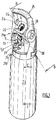
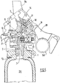
- the Figure 1 presents an embodiment of a rigid protective cover 21, commonly called a "cap”, arranged around a valve unit 1 of a gas distribution assembly according to the invention (visible on Fig. 5 ), namely a valve unit with integrated regulator, itself fixed to the neck of a gas cylinder 20, said protective cover 21 being provided with a carrying handle 25 according to the present invention.
- a rigid protective cover 21 commonly called a "cap”
- the gas cylinder 20 typically has a cylindrical steel body and a size between 10 and 150 cm, and a capacity of 0.5 to 20 liters (in water equivalent).
- the protective cover 21 makes it possible to protect the valve block 1 against shocks, which valve is of the type with integrated pressure reducer or RDI.
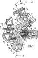
- the fixing around the valve block 1 on the neck of the gas cylinder 20 is done by screwing, via reciprocal threads carried by the internal surface of the neck of the cylinder 20, on the one hand, and by the external surface of an expansion 12 of substantially cylindrical or conical shape, located at the base of the valve body 1 and carrying the gas inlet orifice 2, as visible in Figures 2 and 5 , on the other hand.
- the protective cowling 1 comprises a cowling body forming a protective shell around an internal volume dimensioned to receive the valve unit 1, and a carrying handle 25 designed to be held in the hand by a user.
- the body of the cowling 21 is typically made of a material of polymer and / or metal type, preferably of plastic material, such as PVC, PE, PET, PP, PMMA, PU, PA, etc.
- the carrying handle 25 is formed of a rigid material, such as a polymer or a metal or metal alloy, and is carried by one or more support posts 24 mechanically connecting the cover body to the carrying handle 25.
- the carrying handle. carrying 25 is generally arranged horizontally, that is to say perpendicular or quasi-perpendicularly with respect to the vertical axis of the bottle 20 and of the cowling 21.
- the carrying handle 25 has an elongated shape, whether rectilinear or curved , typically a length of less than 20 cm, typically 6 to 15 cm.
- One or more support posts 24 are fixed to the carrying handle 25 so as to allow a user to easily transport the assembly comprising the cap 21, the valve 1 and the bottle 20 by means of the said carrying handle 25.
- the support posts 24 can be formed from a plastic material, such as the body of the cowling 21, but also from an aluminum alloy or any other metallic material. They can be attached to the handle 25 by screwing or welding, for example, or formed in one piece.
- the protective cowling 21 also has openings giving access to the valve unit 1 located in the internal volume of the cowling body.
- a first opening 22 is provided at the level of the upper part 21a, also called the upper part, of the protective cowling 21, within which is housed a pressure indicator device 7, namely here a pressure gauge, either at needle, or electronic.
- the lower part 21b, also called the lower part, of the cowling 21 is positioned around at least part of the neck of the bottle 20, as visible in Figure 1 .
- the protective cowling 21 comprises a flat surface 26 at its upper part 21a, that is to say at the top of the cowling, within which the first opening 22.
- the flat surface 26 is in fact formed. an oblique face with respect to the axis CC of the bottle 20.
- the flat surface 26 is perpendicular to the axis BB of the pressure indicating device 7, as shown diagrammatically in Figure 1 .
- the axes CC of the bottle 20 and AA of the valve block 1 are merged, that is to say coaxial.
- the protective cowling 21 comprises a second opening 27 arranged on the front or front face of the protective cowling, within which is housed the rotary handwheel 5 controlling the flow of gas passing through the valve block 1, as explained below. after in relation to Figures 2 and 3 .
- the rotary flywheel 5 is arranged around the gas outlet fitting 13 carrying the gas outlet port 6 serving to withdraw the gas stored in the cylinder 20.
- the rotary handwheel 5 can be arranged differently, that is to say. i.e. not coaxial with the gas outlet fitting 13.
- valve block 1 also comprises a filling connection 17 with an internal valve 18, (cf. Fig. 2 and 5 ), which filling connection 17 serves to introduce pressurized gas into the cylinder 20 when the latter is empty or almost empty.
- the protective cover 21 comprises, on the side of its rear face, a pivoting attachment device 28, between a fully folded position, called “rest” (shown schematically in Figure 1 ), that is to say the position adopted by the attachment device 28 when it is stored and in contact or near contact with the body of the cowling 21, and a fully unfolded position called “attachment” (not shown) , that is to say the position adopted by the hooking device 28 when it is fully extended and can be hooked to a support, such as a bed bar or the like.
- a pivoting attachment device 28 between a fully folded position, called “rest” (shown schematically in Figure 1 ), that is to say the position adopted by the attachment device 28 when it is stored and in contact or near contact with the body of the cowling 21, and a fully unfolded position called “attachment” (not shown) , that is to say the position adopted by the hooking device 28 when it is fully extended and can be hooked to a support, such as a bed bar or the like.
- the pressure indicator device 7 is fixed to the body 1 of the valve block which is located in the internal volume of the cowling 21, as visible on the figures. Figures 2 and 3 .
- Such an arrangement of the pressure indicator device 7 in the high position on the valve unit 1 and on the front of the cowling 21 makes it possible to considerably facilitate the reading of the pressure delivered by the pressure indicator device 7 and avoids reading errors.
- the axis BB of the manometer 7 and the axis AA of the valve unit 1 form an angle ⁇ between 0 and 90 °, in particular between 10 ° and 80 °, preferably between 25 ° and 70 °, typically of the order from 35 to 55 °.
- the gas distribution valve block of a gas distribution assembly comprises a valve body 1 schematically comprising an upper part forming the top of the valve block 1, and a lower part 1b forming the base of the block valve 1.
- the upper part therefore surmounts the lower part or base 1b of block 1.
- the lower part 1b of the valve block 1 comprises the fixing system 12a, like a thread, making it possible to fix the valve block 1 to the bottle 20, as already explained, as well as the gas inlet 2 through which a gas under pressure from the bottle 20, can enter the body 1 of the valve, then be then routed to the gas outlet 6 carried by the outlet connector 13 through which the gas can exit the body 1 of tap.
- the lower part 1b of the valve body 1 is shaped to come to be fixed by screwing.
- the lower part 1b comprises an expansion 12 of the body projecting downwards, of generally cylindrical or conical shape and carrying a thread 12a on its external surface capable of coming to cooperate by screwing with a complementary thread or internal thread formed in the bottle neck 20.
- a first internal gas passage 3 fluidly connects the gas inlet 2 to the gas outlet 6 carried by the outlet connection 13.
- This first internal gas passage 3 therefore axially passes through the expansion 12 of body 1 of generally cylindrical or conical shape, as shown in Figure 1 , said expansion 12 further carrying the gas inlet port 2.
- valve unit 1 also comprises a gas passage or flow control system 23 cooperating with the control member 5, namely here a rotary handwheel operable by the user, to control the passage of gas into the first internal gas passage 3, that is to say to allow or, conversely, to prevent any circulation of gas in said passage 3, in the direction going from the gas inlet port 2 to the gas outlet 6 carried by the outlet connector 13.
- a gas passage or flow control system 23 cooperating with the control member 5, namely here a rotary handwheel operable by the user, to control the passage of gas into the first internal gas passage 3, that is to say to allow or, conversely, to prevent any circulation of gas in said passage 3, in the direction going from the gas inlet port 2 to the gas outlet 6 carried by the outlet connector 13.
- the gas flow control system 23 comprises an element pierced with calibrated holes, the handwheel coming, depending on the case, either to make the calibrated hole corresponding to the desired flow rate cooperate with a fixed passage orifice, or to cause a movable passage orifice to cooperate. with the calibrated hole corresponding to the desired flow rate.
- Such an arrangement is conventional and known to those skilled in the art.
- the element pierced with calibrated orifices is a movable metal disc traversed by calibrated orifices.
- the orifices have different sizes, i.e. increasing ones, each size corresponding to a given flow rate.
- This disc is movable in rotation and driven by the flywheel 5.
- valve block also integrates, as shown in Figure 2 , a valve 4 movable in translation, one or more seals 15, such as O-rings, and at least one return spring 14.
- the valve 4 is a residual pressure valve intended to maintain a positive pressure permanently in the valve. bottle. This valve 4 operates autonomously, without any action of the handwheel.
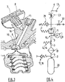
- valve body 1 comprises a second internal gas passage 11 fluidly connected to the first internal gas passage 3, at a junction or fluidic connection site 10.
- the second internal gas passage 11 therefore forms a bifurcation or a branch of the first internal gas passage 3.
- the second internal gas passage 11 and at least the portion of the first internal gas passage 3 between the inlet port 2 and the fluidic junction site 10 convey high pressure gas coming directly from the gas cylinder 20. These passages 11, 3 are therefore subjected to high pressure, typically pressures of up to approximately 350 bar absolute.
- the pressure indicator device here a manometer 7, which is fixed to the valve body 1 at its upper end 1a, comprises a pressure tap 8, for example a channel or the like, in fluid communication with the second internal gas passage 11 so as to measure the gas pressure within said second internal gas passage 11.
- the pressure tap 8 of the pressure indicator device 7 can be fluidly connected to the second internal gas passage 11 indirectly, for example via a junction passage 16 arranged in the body 1 of the valve and connecting the pressure tap 8 of the device. pressure indicator 7 at the second internal gas passage 11, as shown in Figures 2 , 3 and 5 .
- the valve block is of the RDI type, that is to say it comprises a gas expansion system 9 arranged between the fluidic connection site 10 of the first and second internal gas passages 3, 11, and the gas outlet 6 so as to effect a reduction in the pressure of the high pressure gas coming from the bottle 20, down to a lower pressure value, for example a change from a high pressure greater than 100 bar to a low pressure less than 20 bar abs.
- an expansion system 9 comprising an expansion valve and a valve seat.
- the final pressure can be of adjustable or fixed value.
- the gas circulating in the second internal gas passage 11 is not subjected to expansion within the expansion system 9 since the junction site or fluid connection 10 between the first and second gas passages 3, 11 is located in upstream of the expansion system 9.
- the junction or fluidic connection site 10 is typically the so-called high-pressure chamber of the expansion system 9, which high-pressure chamber is then traversed by the high-pressure gas which is brought there by the first gas passage 3. Part of the high-pressure gas is then evacuated through the second gas passage 11 which then conveys it to the pressure tap 8 of the manometer 7 (or of a device for measuring autonomy) so as to make it possible to measuring the pressure of said gas.
- This architecture is essential in the context of the present invention.
- the Figure 3 makes it possible to better visualize the expansion system 9 and the high pressure chamber 10. More precisely, in addition to the pressure tap 8 and the pressure gauge 7, we see the expansion valve of elongated shape, ie stem, the valve seat, an expansion spring and an expansion piston which determines the position of the expansion valve as a function of the force of the expansion spring, high pressure and low pressure.
- valve unit also comprises an internal filter 19, as well as arranged downstream of the expansion system 9, a valve 29 and a low pressure gas outlet with isolation valve 30.
- An assembly according to the invention is particularly suitable for use in a medical environment, in particular for the distribution of any medical gas or gas mixture, in particular of the oxygen, air, N 2 O / O 2 , He / O 2 , NO type. / nitrogen or other.
Landscapes
- Engineering & Computer Science (AREA)
- Mechanical Engineering (AREA)
- General Engineering & Computer Science (AREA)
- Filling Or Discharging Of Gas Storage Vessels (AREA)
Claims (14)
- Gasverteilungseinheit (1, 20, 21), umfassend einen Gasbehälter (20) und einen am Gasbehälter (20) befestigten Hahnblock (1), wobei der Gasverteilungshahnblock Folgendes umfasst:- einen Hahnkörper (1) mit einem unteren Teil (1b), der ein Befestigungssystem (12, 12a) umfasst, das es ermöglicht, den Hahnblock an einem Gasbehälter (20) zu befestigen, und einem oberen Teil (1a), der den unteren Teil (1b) überragt, wobei der untere Teil (1b) des Hahnkörpers (1) eine Gaseintrittsöffnung (2) umfasst, durch die ein Gas in den Hahnkörper (1) eintreten kann,- eine Gasaustrittsöffnung (6), durch die das Gas aus dem Hahnkörper (1) austreten kann,- einen ersten internen Gasdurchlass (3), der die Gaseintrittsöffnung (2) fluidisch mit der Gasaustrittsöffnung (6) verbindet, und- eine am Hahnkörper (1) befestigte Gasdruck- oder Gasautonomieanzeigevorrichtung (7),und wobei:- der Hahnkörper (1) einen zweiten internen Gasdurchlass (11) umfasst, der mit dem ersten internen Gasdurchlass (3) fluidisch verbunden ist (10), so dass der im zweiten internen Gasdurchlass (11) wirkende Gasdruck gleich dem im ersten internen Gasdurchlass (3) stromaufwärts der Fluidanschlussstelle (10) des ersten und des zweiten internen Gasdurchlasses (3, 11) wirkenden Gasdruck ist,- die Druck- bzw. Autonomieanzeigevorrichtung (7) am Hahnkörper (1) an seinem oberen Ende (1a) befestigt ist und eine Druckmessstelle (8) umfasst, die mit dem zweiten internen Gasdurchlass (11) in Fluidverbindung steht, um den Gasdruck innerhalb des zweiten internen Gasdurchlasses (11) zu messen, und- der Hahnkörper (1) ein Gasexpansionssystem (9) umfasst, das zwischen der Fluidanschlussstelle (10) des ersten und des zweiten internen Gasdurchlasses (3, 11) und der Gasauslassöffnung (6) angeordnet ist,dadurch gekennzeichnet, dass sie eine Schutzabdeckung (21) umfasst, die um den Hahnblock (1) herum angeordnet ist, wobei die Schutzabdeckung (21) Folgendes umfasst:- eine Öffnung (22), die am oberen Teil (21a) der Schutzabdeckung (21) vorgesehen ist und innerhalb derer sich die Gasdruck- bzw. Gasautonomieanzeigevorrichtung (7) des Hahnkörpers (1) befindet, und- einen Tragegriff (25), der über einen oder mehrere Tragpfosten (24) mit der Abdeckung (21) verbunden ist, wobei der Tragegriff so an der Abdeckung (21) angeordnet ist, dass die Gasdruck- bzw. Gasautonomieanzeigevorrichtung (7) im Wesentlichen zwischen dem Tragegriff (25) und dem Hahnblock (24), der die Gasdruck- bzw. Gasautonomieanzeigevorrichtung (7) trägt, positioniert ist.
- Gasverteilungseinheit nach Anspruch 1, dadurch gekennzeichnet, dass die Druckanzeigevorrichtung (7) ein Druckmessgerät mit Zeigeranzeige oder digitaler Anzeige ist.
- Gasverteilungseinheit nach Anspruch 1, dadurch gekennzeichnet, dass die Autonomieanzeigevorrichtung (7) eine Zeigervorrichtung oder eine digitale Vorrichtung ist.
- Gasverteilungseinheit nach einem der Ansprüche 1 oder 3, dadurch gekennzeichnet, dass die Autonomieanzeigevorrichtung (7) eine elektronische Vorrichtung ist, die eine in Zeiteinheiten ausgedrückte Gasautonomie berechnet und anzeigt.
- Gasverteilungseinheit nach einem der vorangehenden Ansprüche, dadurch gekennzeichnet, dass der Hahnblock (1) ein am ersten internen Gasdurchlass (3) angeordnetes Gasdurchflusssteuersystem (23) und ein Bedienelement (5) aufweist, das von einem Benutzer betätigt werden kann und mit dem Gasdurchflusssteuersystem (23) zusammenwirkt, um den Gasdurchfluss im ersten internen Gasdurchlass (3) in der Richtung von der Gaseintrittsöffnung (2) zur Gasauslassöffnung (6) zu steuern.
- Gasverteilungseinheit nach einem der vorangehenden Ansprüche, dadurch gekennzeichnet, dass die Druckmessstelle (8) der Gasdruck- bzw. Gasautonomieanzeigevorrichtung (7) über einen im Hahnkörper (1) angeordneten Verbindungsdurchlass (16) mit dem zweiten internen Gasdurchlass (11) in Fluidverbindung steht.
- Gasverteilungseinheit nach einem der vorangehenden Ansprüche, dadurch gekennzeichnet, dass die Achse (BB) der Gasdruck- bzw. Gasautonomieanzeigevorrichtung (7) mit der Achse (AA) des Hahnkörpers (1) einen Winkel (α) zwischen 0° und 90° bildet.
- Gasverteilungseinheit nach einem der vorangehenden Ansprüche, dadurch gekennzeichnet, dass die Achse (BB) der Gasdruck- bzw. Gasautonomieanzeigevorrichtung (7) mit der Achse (AA) des Hahnkörpers (1) einen Winkel (α) zwischen 10° und 80° bildet.
- Gasverteilungseinheit nach einem der vorangehenden Ansprüche, dadurch gekennzeichnet, dass die Fluidanschlussstelle (10) die Hochdruckkammer des Expansionssystems (9) umfasst.
- Gasverteilungseinheit nach einem der Ansprüche 5 oder 6 bis 9, sofern sich letztere auf Anspruch 5 beziehen,
dadurch gekennzeichnet, dass das von einem Benutzer bedienbare Bedienelement (5) ein drehbares Handrad ist. - Gasverteilungseinheit nach einem der vorangehenden Ansprüche, dadurch gekennzeichnet, dass die Schutzabdeckung (21) ferner eine schwenkbare Befestigungsvorrichtung (28) umfasst, die es ermöglicht, die Einheit an einem Träger zu befestigen.
- Gasverteilungseinheit nach einem der Ansprüche 10 oder 11, sofern sich letzterer auf Anspruch 10 bezieht, dadurch gekennzeichnet, dass die Schutzabdeckung (21) eine zweite Öffnung (27) umfasst, die an der Stirnseite der Schutzabdeckung (21) vorgesehen ist, in der das drehbare Handrad (5) untergebracht ist, das den durch den Hahnblock (1) strömenden Gasdurchfluss steuert.
- Verwendung einer Gasverteilungseinheit nach einem der Ansprüche 1 bis 12 zum Verteilen eines Gases oder Gasgemischs.
- Verwendung nach Anspruch 13, dadurch gekennzeichnet, dass das Gas bzw. Gasgemisch aus Sauerstoff, Luft, N2O/O2, He/O2, NO/Stickstoff ausgewählt ist.
Applications Claiming Priority (2)
| Application Number | Priority Date | Filing Date | Title |
|---|---|---|---|
| FR1452041A FR3018580B1 (fr) | 2014-03-12 | 2014-03-12 | Bloc robinet pour recipient de gaz avec dispositif indicateur de pression ou d’autonomie en position haute |
| PCT/FR2015/050525 WO2015136190A1 (fr) | 2014-03-12 | 2015-03-04 | Bloc robinet pour récipient de gaz avec dispositif indicateur de pression ou d'autonomie en position haute |
Publications (2)
| Publication Number | Publication Date |
|---|---|
| EP3117136A1 EP3117136A1 (de) | 2017-01-18 |
| EP3117136B1 true EP3117136B1 (de) | 2021-06-09 |
Family
ID=51168037
Family Applications (1)
| Application Number | Title | Priority Date | Filing Date |
|---|---|---|---|
| EP15714564.0A Active EP3117136B1 (de) | 2014-03-12 | 2015-03-04 | Ventileinheit für gasbehälter mit druckanzeigender oder betriebszeitanzeigender vorrichtung nahe der oberseite |
Country Status (8)
| Country | Link |
|---|---|
| US (1) | US20170114961A1 (de) |
| EP (1) | EP3117136B1 (de) |
| CN (1) | CN106104140B (de) |
| AU (1) | AU2015228706A1 (de) |
| CA (1) | CA2942473A1 (de) |
| ES (1) | ES2886440T3 (de) |
| FR (1) | FR3018580B1 (de) |
| WO (1) | WO2015136190A1 (de) |
Families Citing this family (15)
| Publication number | Priority date | Publication date | Assignee | Title |
|---|---|---|---|---|
| FR3045775B1 (fr) * | 2015-12-18 | 2018-07-06 | Engie | Procede et systeme pour calculer en temps reel la duree d'autonomie d'une cuve non refrigeree contenant du gnl |
| FR3050053B1 (fr) * | 2016-04-06 | 2018-05-04 | L'air Liquide, Societe Anonyme Pour L'etude Et L'exploitation Des Procedes Georges Claude | Procede de calcul de l'autonomie d'un ensemble de distribution de gaz |
| FR3066804A1 (fr) * | 2017-05-24 | 2018-11-30 | L'air Liquide, Societe Anonyme Pour L'etude Et L'exploitation Des Procedes Georges Claude | Robinet a detenteur integre et vanne de fermeture manuelle pour recipient de gaz |
| FR3067095B1 (fr) * | 2017-06-01 | 2020-08-14 | L'air Liquide Sa Pour L'etude Et L'exploitation Des Procedes Georges Claude | Robinet, stockage et station de remplissage |
| FR3067094B1 (fr) * | 2017-06-01 | 2020-08-14 | L'air Liquide Sa Pour L'etude Et L'exploitation Des Procedes Georges Claude | Robinet, stockage et station de remplissage |
| FR3067788A1 (fr) * | 2017-06-16 | 2018-12-21 | L'air Liquide, Societe Anonyme Pour L'etude Et L'exploitation Des Procedes Georges Claude | Capotage pour recipient de gaz portant un organe de commande de la vanne d'isolation d'un robinet a detendeur integre |
| FR3093781B1 (fr) * | 2019-03-12 | 2021-02-12 | Air Liquide | Robinet, récipient de fluide sous pression et procédés de remplissage et de soutirage. |
| FR3094447B1 (fr) | 2019-03-25 | 2021-06-25 | Air Liquide | Dispositif électronique pour récipient de gaz |
| FR3097615B1 (fr) | 2019-06-21 | 2021-05-28 | Air Liquide | Récipient de gaz avec affichage des débits possibles et autonomies correspondantes |
| IT201900015231A1 (it) * | 2019-08-29 | 2021-03-01 | Cavagna Group Spa | Valvola con sensore integrato |
| FR3106189B1 (fr) | 2020-01-14 | 2021-12-10 | Air Liquide | Récipient de gaz avec affichage du débit et de l’autonomie correspondante |
| FR3113714B1 (fr) * | 2020-09-01 | 2022-12-09 | Lair Liquide Sa Pour L’Etude Et Lexploitation Des Procedes Georges Claude | Robinet de distribution de gaz en laiton à raccords de sortie nickelés |
| IT202100032201A1 (it) * | 2021-12-22 | 2023-06-22 | Cavagna Group Spa | Dispositivo di protezione per recipienti in pressione |
| EP4555250A1 (de) | 2022-07-13 | 2025-05-21 | Praxair Technology, Inc. | Schutzhülle für einen ventilintegrierten druckregler |
| FR3154480B1 (fr) * | 2023-10-19 | 2025-12-26 | Air Liquide | Récipient de fluide muni d’un robinet de distribution à dispositif électronique maintenu par un capotage de protection |
Family Cites Families (15)
| Publication number | Priority date | Publication date | Assignee | Title |
|---|---|---|---|---|
| FR2706016B1 (fr) | 1993-06-03 | 1995-07-28 | France Prod Oxygenes Co | Chapeau de bouteille de gaz. |
| FR2706051B1 (fr) * | 1993-06-03 | 1995-07-28 | Taema | Ensemble de commande de distribution de gaz et bouteille de gaz équipée d'un tel ensemble. |
| US5520214A (en) * | 1994-09-12 | 1996-05-28 | Western/Scott Fetzer Company | Regulator and fill valve |
| FR2807820B1 (fr) | 2000-04-17 | 2002-06-14 | Air Liquide Sante Int | Bouteille de gaz avec enveloppes protectrices utilisable dans le domaine medical |
| DE10057469C2 (de) | 2000-11-20 | 2003-04-17 | Messer Griesheim Gmbh | Schutzkappe für Druckgasflaschen mit Halteschiene |
| US6871802B2 (en) * | 2003-02-27 | 2005-03-29 | Fike Corporation | Self-modulating inert gas fire suppression system |
| FR2859289B1 (fr) * | 2003-09-03 | 2006-02-17 | Taema | Robinet-detendeur integre avec moyens de blocage de l'organe d'actionnement |
| ATE392577T1 (de) * | 2004-07-21 | 2008-05-15 | African Oxygen Ltd | Multifunktionale ventileinheit |
| US20090272443A1 (en) * | 2008-05-02 | 2009-11-05 | Chi Ping Lee | Portable device for supplying compressed CO2 from a pressure vessel to a pneumatic tool |
| EP2116332B1 (de) * | 2008-05-05 | 2011-08-17 | Fever Industrial Co. Ltd. | Tragbare Vorrichtung zur Versorgung eines pneumatischen Werkzeuges mit komprimiertem CO2 aus einem Druckbehälter |
| US8550114B2 (en) * | 2010-10-04 | 2013-10-08 | Wilton Cahn Levine | Time remaining display assembly |
| EP2586481A1 (de) | 2011-10-27 | 2013-05-01 | Linde Aktiengesellschaft | Abdeckung für eine Ventilklappe eines Gaszylinders |
| US9816642B2 (en) * | 2012-11-09 | 2017-11-14 | Praxair Technology, Inc. | Method and apparatus for controlling gas flow from cylinders |
| US9273799B2 (en) * | 2012-11-09 | 2016-03-01 | Praxair Technology, Inc. | Method and apparatus for controlling gas flow from cylinders |
| FR3018583B1 (fr) * | 2014-03-12 | 2017-01-27 | Air Liquide | Capotage de protection pour bouteille de gaz avec ecran d’affichage electronique en position haute |
-
2014
- 2014-03-12 FR FR1452041A patent/FR3018580B1/fr not_active Expired - Fee Related
-
2015
- 2015-03-04 AU AU2015228706A patent/AU2015228706A1/en not_active Abandoned
- 2015-03-04 CN CN201580012162.XA patent/CN106104140B/zh active Active
- 2015-03-04 CA CA2942473A patent/CA2942473A1/en not_active Abandoned
- 2015-03-04 ES ES15714564T patent/ES2886440T3/es active Active
- 2015-03-04 US US15/125,298 patent/US20170114961A1/en not_active Abandoned
- 2015-03-04 WO PCT/FR2015/050525 patent/WO2015136190A1/fr not_active Ceased
- 2015-03-04 EP EP15714564.0A patent/EP3117136B1/de active Active
Non-Patent Citations (1)
| Title |
|---|
| None * |
Also Published As
| Publication number | Publication date |
|---|---|
| AU2015228706A1 (en) | 2016-10-20 |
| CN106104140A (zh) | 2016-11-09 |
| FR3018580B1 (fr) | 2018-11-02 |
| ES2886440T3 (es) | 2021-12-20 |
| WO2015136190A1 (fr) | 2015-09-17 |
| CN106104140B (zh) | 2018-10-02 |
| EP3117136A1 (de) | 2017-01-18 |
| FR3018580A1 (fr) | 2015-09-18 |
| US20170114961A1 (en) | 2017-04-27 |
| CA2942473A1 (en) | 2015-09-17 |
Similar Documents
| Publication | Publication Date | Title |
|---|---|---|
| EP3117136B1 (de) | Ventileinheit für gasbehälter mit druckanzeigender oder betriebszeitanzeigender vorrichtung nahe der oberseite | |
| EP3643958B1 (de) | Anordnung aus einer schutzverkleidung und einer gasflasche mit einer druck- oder statusanzeige im oberen bereich | |
| EP3006808B1 (de) | Schutzhaube mit schwenkbarem einrastsystem für gasflasche | |
| CA2884483A1 (fr) | Ensemble de distribution de gaz avec organe de commande rotatif protege par un rebord en saillie portant une fenetre de lecture | |
| EP3002498B1 (de) | Gasbehälter mit absperrhahnblock, der mit einem berührungsbildschirm zur datenanzeige ausgestattet ist | |
| EP2918891B1 (de) | Haube mit Schutzrand des drehbaren Bedienungsorgans eines Absperrhahnblocks eines Gasbehälters | |
| EP1421305B1 (de) | Mit einem hebel mit mehreren stabilen positionen montierter fluidströmungsregelhahn | |
| LU88377A1 (fr) | Clapet bi-directionnel pour un robinet d'une bouteille de gaz comprimé ou liquéfié et robinet pourvu d'un tel clapet | |
| WO2013127895A1 (fr) | Robinet pour bouteille de gaz avec indicateur visuel de pression | |
| EP3260760B1 (de) | Schutzhaube mit schwenkbarem einrastsystem mit endanschlag für gasbehälter | |
| FR3042584A1 (fr) | Bloc rdi de distribution de gaz avec dispositif indicateur agence au centre du volant de manœuvre | |
| EP2937620B1 (de) | Schutzkappe für eine Gasflasche | |
| FR3052845A1 (fr) | Capotage de protection de recipient de gaz a ouverture recouverte par paroi amovible | |
| FR3052848A1 (fr) | Capotage de protection en plusieurs parties pour bouteille de gaz | |
| FR3067788A1 (fr) | Capotage pour recipient de gaz portant un organe de commande de la vanne d'isolation d'un robinet a detendeur integre | |
| FR3113714A1 (fr) | Robinet de distribution de gaz en laiton à raccords de sortie nickelés | |
| FR3082914A1 (fr) | Robinet pour recipient de gaz comprenant un manometre protege par une piece-berceau |
Legal Events
| Date | Code | Title | Description |
|---|---|---|---|
| STAA | Information on the status of an ep patent application or granted ep patent |
Free format text: STATUS: THE INTERNATIONAL PUBLICATION HAS BEEN MADE |
|
| PUAI | Public reference made under article 153(3) epc to a published international application that has entered the european phase |
Free format text: ORIGINAL CODE: 0009012 |
|
| STAA | Information on the status of an ep patent application or granted ep patent |
Free format text: STATUS: REQUEST FOR EXAMINATION WAS MADE |
|
| 17P | Request for examination filed |
Effective date: 20161012 |
|
| AK | Designated contracting states |
Kind code of ref document: A1 Designated state(s): AL AT BE BG CH CY CZ DE DK EE ES FI FR GB GR HR HU IE IS IT LI LT LU LV MC MK MT NL NO PL PT RO RS SE SI SK SM TR |
|
| AX | Request for extension of the european patent |
Extension state: BA ME |
|
| RIN1 | Information on inventor provided before grant (corrected) |
Inventor name: BAUNE, EMMANUEL Inventor name: GERMANI, DAMIEN Inventor name: TARANTELLO, CHIARA Inventor name: LIGONESCHE, RENAUD Inventor name: RUDNIANYN, PHILIPPE |
|
| DAV | Request for validation of the european patent (deleted) | ||
| DAX | Request for extension of the european patent (deleted) | ||
| STAA | Information on the status of an ep patent application or granted ep patent |
Free format text: STATUS: EXAMINATION IS IN PROGRESS |
|
| 17Q | First examination report despatched |
Effective date: 20180405 |
|
| GRAP | Despatch of communication of intention to grant a patent |
Free format text: ORIGINAL CODE: EPIDOSNIGR1 |
|
| STAA | Information on the status of an ep patent application or granted ep patent |
Free format text: STATUS: GRANT OF PATENT IS INTENDED |
|
| INTG | Intention to grant announced |
Effective date: 20210315 |
|
| RIN1 | Information on inventor provided before grant (corrected) |
Inventor name: GERMANI, DAMIEN Inventor name: RUDNIANYN, PHILIPPE Inventor name: LIGONESCHE, RENAUD Inventor name: BAUNE, EMMANUEL Inventor name: TARANTELLO, CHIARA |
|
| GRAS | Grant fee paid |
Free format text: ORIGINAL CODE: EPIDOSNIGR3 |
|
| GRAA | (expected) grant |
Free format text: ORIGINAL CODE: 0009210 |
|
| STAA | Information on the status of an ep patent application or granted ep patent |
Free format text: STATUS: THE PATENT HAS BEEN GRANTED |
|
| AK | Designated contracting states |
Kind code of ref document: B1 Designated state(s): AL AT BE BG CH CY CZ DE DK EE ES FI FR GB GR HR HU IE IS IT LI LT LU LV MC MK MT NL NO PL PT RO RS SE SI SK SM TR |
|
| REG | Reference to a national code |
Ref country code: GB Ref legal event code: FG4D Free format text: NOT ENGLISH |
|
| REG | Reference to a national code |
Ref country code: CH Ref legal event code: EP Ref country code: AT Ref legal event code: REF Ref document number: 1400803 Country of ref document: AT Kind code of ref document: T Effective date: 20210615 |
|
| REG | Reference to a national code |
Ref country code: DE Ref legal event code: R096 Ref document number: 602015070205 Country of ref document: DE |
|
| REG | Reference to a national code |
Ref country code: IE Ref legal event code: FG4D Free format text: LANGUAGE OF EP DOCUMENT: FRENCH |
|
| REG | Reference to a national code |
Ref country code: LT Ref legal event code: MG9D |
|
| PG25 | Lapsed in a contracting state [announced via postgrant information from national office to epo] |
Ref country code: HR Free format text: LAPSE BECAUSE OF FAILURE TO SUBMIT A TRANSLATION OF THE DESCRIPTION OR TO PAY THE FEE WITHIN THE PRESCRIBED TIME-LIMIT Effective date: 20210609 Ref country code: BG Free format text: LAPSE BECAUSE OF FAILURE TO SUBMIT A TRANSLATION OF THE DESCRIPTION OR TO PAY THE FEE WITHIN THE PRESCRIBED TIME-LIMIT Effective date: 20210909 Ref country code: FI Free format text: LAPSE BECAUSE OF FAILURE TO SUBMIT A TRANSLATION OF THE DESCRIPTION OR TO PAY THE FEE WITHIN THE PRESCRIBED TIME-LIMIT Effective date: 20210609 Ref country code: LT Free format text: LAPSE BECAUSE OF FAILURE TO SUBMIT A TRANSLATION OF THE DESCRIPTION OR TO PAY THE FEE WITHIN THE PRESCRIBED TIME-LIMIT Effective date: 20210609 |
|
| REG | Reference to a national code |
Ref country code: AT Ref legal event code: MK05 Ref document number: 1400803 Country of ref document: AT Kind code of ref document: T Effective date: 20210609 |
|
| REG | Reference to a national code |
Ref country code: NL Ref legal event code: MP Effective date: 20210609 |
|
| PG25 | Lapsed in a contracting state [announced via postgrant information from national office to epo] |
Ref country code: LV Free format text: LAPSE BECAUSE OF FAILURE TO SUBMIT A TRANSLATION OF THE DESCRIPTION OR TO PAY THE FEE WITHIN THE PRESCRIBED TIME-LIMIT Effective date: 20210609 Ref country code: GR Free format text: LAPSE BECAUSE OF FAILURE TO SUBMIT A TRANSLATION OF THE DESCRIPTION OR TO PAY THE FEE WITHIN THE PRESCRIBED TIME-LIMIT Effective date: 20210910 Ref country code: NO Free format text: LAPSE BECAUSE OF FAILURE TO SUBMIT A TRANSLATION OF THE DESCRIPTION OR TO PAY THE FEE WITHIN THE PRESCRIBED TIME-LIMIT Effective date: 20210909 Ref country code: RS Free format text: LAPSE BECAUSE OF FAILURE TO SUBMIT A TRANSLATION OF THE DESCRIPTION OR TO PAY THE FEE WITHIN THE PRESCRIBED TIME-LIMIT Effective date: 20210609 Ref country code: SE Free format text: LAPSE BECAUSE OF FAILURE TO SUBMIT A TRANSLATION OF THE DESCRIPTION OR TO PAY THE FEE WITHIN THE PRESCRIBED TIME-LIMIT Effective date: 20210609 |
|
| REG | Reference to a national code |
Ref country code: ES Ref legal event code: FG2A Ref document number: 2886440 Country of ref document: ES Kind code of ref document: T3 Effective date: 20211220 |
|
| PG25 | Lapsed in a contracting state [announced via postgrant information from national office to epo] |
Ref country code: AT Free format text: LAPSE BECAUSE OF FAILURE TO SUBMIT A TRANSLATION OF THE DESCRIPTION OR TO PAY THE FEE WITHIN THE PRESCRIBED TIME-LIMIT Effective date: 20210609 Ref country code: NL Free format text: LAPSE BECAUSE OF FAILURE TO SUBMIT A TRANSLATION OF THE DESCRIPTION OR TO PAY THE FEE WITHIN THE PRESCRIBED TIME-LIMIT Effective date: 20210609 Ref country code: PT Free format text: LAPSE BECAUSE OF FAILURE TO SUBMIT A TRANSLATION OF THE DESCRIPTION OR TO PAY THE FEE WITHIN THE PRESCRIBED TIME-LIMIT Effective date: 20211011 Ref country code: RO Free format text: LAPSE BECAUSE OF FAILURE TO SUBMIT A TRANSLATION OF THE DESCRIPTION OR TO PAY THE FEE WITHIN THE PRESCRIBED TIME-LIMIT Effective date: 20210609 Ref country code: CZ Free format text: LAPSE BECAUSE OF FAILURE TO SUBMIT A TRANSLATION OF THE DESCRIPTION OR TO PAY THE FEE WITHIN THE PRESCRIBED TIME-LIMIT Effective date: 20210609 Ref country code: EE Free format text: LAPSE BECAUSE OF FAILURE TO SUBMIT A TRANSLATION OF THE DESCRIPTION OR TO PAY THE FEE WITHIN THE PRESCRIBED TIME-LIMIT Effective date: 20210609 Ref country code: SK Free format text: LAPSE BECAUSE OF FAILURE TO SUBMIT A TRANSLATION OF THE DESCRIPTION OR TO PAY THE FEE WITHIN THE PRESCRIBED TIME-LIMIT Effective date: 20210609 Ref country code: SM Free format text: LAPSE BECAUSE OF FAILURE TO SUBMIT A TRANSLATION OF THE DESCRIPTION OR TO PAY THE FEE WITHIN THE PRESCRIBED TIME-LIMIT Effective date: 20210609 |
|
| PG25 | Lapsed in a contracting state [announced via postgrant information from national office to epo] |
Ref country code: PL Free format text: LAPSE BECAUSE OF FAILURE TO SUBMIT A TRANSLATION OF THE DESCRIPTION OR TO PAY THE FEE WITHIN THE PRESCRIBED TIME-LIMIT Effective date: 20210609 |
|
| REG | Reference to a national code |
Ref country code: DE Ref legal event code: R097 Ref document number: 602015070205 Country of ref document: DE |
|
| PLBE | No opposition filed within time limit |
Free format text: ORIGINAL CODE: 0009261 |
|
| STAA | Information on the status of an ep patent application or granted ep patent |
Free format text: STATUS: NO OPPOSITION FILED WITHIN TIME LIMIT |
|
| PG25 | Lapsed in a contracting state [announced via postgrant information from national office to epo] |
Ref country code: DK Free format text: LAPSE BECAUSE OF FAILURE TO SUBMIT A TRANSLATION OF THE DESCRIPTION OR TO PAY THE FEE WITHIN THE PRESCRIBED TIME-LIMIT Effective date: 20210609 |
|
| 26N | No opposition filed |
Effective date: 20220310 |
|
| PG25 | Lapsed in a contracting state [announced via postgrant information from national office to epo] |
Ref country code: AL Free format text: LAPSE BECAUSE OF FAILURE TO SUBMIT A TRANSLATION OF THE DESCRIPTION OR TO PAY THE FEE WITHIN THE PRESCRIBED TIME-LIMIT Effective date: 20210609 |
|
| PG25 | Lapsed in a contracting state [announced via postgrant information from national office to epo] |
Ref country code: MC Free format text: LAPSE BECAUSE OF FAILURE TO SUBMIT A TRANSLATION OF THE DESCRIPTION OR TO PAY THE FEE WITHIN THE PRESCRIBED TIME-LIMIT Effective date: 20210609 |
|
| REG | Reference to a national code |
Ref country code: CH Ref legal event code: PL |
|
| GBPC | Gb: european patent ceased through non-payment of renewal fee |
Effective date: 20220304 |
|
| REG | Reference to a national code |
Ref country code: BE Ref legal event code: MM Effective date: 20220331 |
|
| PG25 | Lapsed in a contracting state [announced via postgrant information from national office to epo] |
Ref country code: LU Free format text: LAPSE BECAUSE OF NON-PAYMENT OF DUE FEES Effective date: 20220304 Ref country code: LI Free format text: LAPSE BECAUSE OF NON-PAYMENT OF DUE FEES Effective date: 20220331 Ref country code: IE Free format text: LAPSE BECAUSE OF NON-PAYMENT OF DUE FEES Effective date: 20220304 Ref country code: GB Free format text: LAPSE BECAUSE OF NON-PAYMENT OF DUE FEES Effective date: 20220304 Ref country code: CH Free format text: LAPSE BECAUSE OF NON-PAYMENT OF DUE FEES Effective date: 20220331 |
|
| PG25 | Lapsed in a contracting state [announced via postgrant information from national office to epo] |
Ref country code: BE Free format text: LAPSE BECAUSE OF NON-PAYMENT OF DUE FEES Effective date: 20220331 |
|
| PG25 | Lapsed in a contracting state [announced via postgrant information from national office to epo] |
Ref country code: HU Free format text: LAPSE BECAUSE OF FAILURE TO SUBMIT A TRANSLATION OF THE DESCRIPTION OR TO PAY THE FEE WITHIN THE PRESCRIBED TIME-LIMIT; INVALID AB INITIO Effective date: 20150304 |
|
| PG25 | Lapsed in a contracting state [announced via postgrant information from national office to epo] |
Ref country code: MK Free format text: LAPSE BECAUSE OF FAILURE TO SUBMIT A TRANSLATION OF THE DESCRIPTION OR TO PAY THE FEE WITHIN THE PRESCRIBED TIME-LIMIT Effective date: 20210609 Ref country code: CY Free format text: LAPSE BECAUSE OF FAILURE TO SUBMIT A TRANSLATION OF THE DESCRIPTION OR TO PAY THE FEE WITHIN THE PRESCRIBED TIME-LIMIT Effective date: 20210609 |
|
| PG25 | Lapsed in a contracting state [announced via postgrant information from national office to epo] |
Ref country code: MT Free format text: LAPSE BECAUSE OF FAILURE TO SUBMIT A TRANSLATION OF THE DESCRIPTION OR TO PAY THE FEE WITHIN THE PRESCRIBED TIME-LIMIT Effective date: 20210609 |
|
| PGFP | Annual fee paid to national office [announced via postgrant information from national office to epo] |
Ref country code: ES Payment date: 20250429 Year of fee payment: 11 |
|
| PG25 | Lapsed in a contracting state [announced via postgrant information from national office to epo] |
Ref country code: TR Free format text: LAPSE BECAUSE OF FAILURE TO SUBMIT A TRANSLATION OF THE DESCRIPTION OR TO PAY THE FEE WITHIN THE PRESCRIBED TIME-LIMIT Effective date: 20210609 |
|
| PGFP | Annual fee paid to national office [announced via postgrant information from national office to epo] |
Ref country code: DE Payment date: 20260319 Year of fee payment: 12 |
|
| PGFP | Annual fee paid to national office [announced via postgrant information from national office to epo] |
Ref country code: IT Payment date: 20260319 Year of fee payment: 12 |
|
| PGFP | Annual fee paid to national office [announced via postgrant information from national office to epo] |
Ref country code: FR Payment date: 20260320 Year of fee payment: 12 |