EP3117131B1 - Steuerventil einer ölpumpe mit doppelter/variabler verstärkung - Google Patents
Steuerventil einer ölpumpe mit doppelter/variabler verstärkung Download PDFInfo
- Publication number
- EP3117131B1 EP3117131B1 EP14720010.9A EP14720010A EP3117131B1 EP 3117131 B1 EP3117131 B1 EP 3117131B1 EP 14720010 A EP14720010 A EP 14720010A EP 3117131 B1 EP3117131 B1 EP 3117131B1
- Authority
- EP
- European Patent Office
- Prior art keywords
- control valve
- feedback
- solenoid
- fluid control
- fluid
- Prior art date
- Legal status (The legal status is an assumption and is not a legal conclusion. Google has not performed a legal analysis and makes no representation as to the accuracy of the status listed.)
- Active
Links
- 230000009977 dual effect Effects 0.000 title description 21
- 239000012530 fluid Substances 0.000 claims description 94
- 230000007246 mechanism Effects 0.000 claims description 15
- 230000004044 response Effects 0.000 claims description 8
- 238000006073 displacement reaction Methods 0.000 claims description 3
- 239000000356 contaminant Substances 0.000 description 5
- 238000011109 contamination Methods 0.000 description 3
- 230000008859 change Effects 0.000 description 2
- RYGMFSIKBFXOCR-UHFFFAOYSA-N Copper Chemical compound [Cu] RYGMFSIKBFXOCR-UHFFFAOYSA-N 0.000 description 1
- 238000013459 approach Methods 0.000 description 1
- 230000008901 benefit Effects 0.000 description 1
- 230000001276 controlling effect Effects 0.000 description 1
- 229910052802 copper Inorganic materials 0.000 description 1
- 239000010949 copper Substances 0.000 description 1
- 230000002596 correlated effect Effects 0.000 description 1
- 230000001419 dependent effect Effects 0.000 description 1
- 230000009467 reduction Effects 0.000 description 1
Images


Classifications
-
- F—MECHANICAL ENGINEERING; LIGHTING; HEATING; WEAPONS; BLASTING
- F16—ENGINEERING ELEMENTS AND UNITS; GENERAL MEASURES FOR PRODUCING AND MAINTAINING EFFECTIVE FUNCTIONING OF MACHINES OR INSTALLATIONS; THERMAL INSULATION IN GENERAL
- F16K—VALVES; TAPS; COCKS; ACTUATING-FLOATS; DEVICES FOR VENTING OR AERATING
- F16K31/00—Actuating devices; Operating means; Releasing devices
- F16K31/02—Actuating devices; Operating means; Releasing devices electric; magnetic
- F16K31/06—Actuating devices; Operating means; Releasing devices electric; magnetic using a magnet, e.g. diaphragm valves, cutting off by means of a liquid
- F16K31/0603—Multiple-way valves
- F16K31/061—Sliding valves
- F16K31/0613—Sliding valves with cylindrical slides
-
- F—MECHANICAL ENGINEERING; LIGHTING; HEATING; WEAPONS; BLASTING
- F15—FLUID-PRESSURE ACTUATORS; HYDRAULICS OR PNEUMATICS IN GENERAL
- F15B—SYSTEMS ACTING BY MEANS OF FLUIDS IN GENERAL; FLUID-PRESSURE ACTUATORS, e.g. SERVOMOTORS; DETAILS OF FLUID-PRESSURE SYSTEMS, NOT OTHERWISE PROVIDED FOR
- F15B13/00—Details of servomotor systems ; Valves for servomotor systems
- F15B13/02—Fluid distribution or supply devices characterised by their adaptation to the control of servomotors
- F15B13/04—Fluid distribution or supply devices characterised by their adaptation to the control of servomotors for use with a single servomotor
- F15B13/042—Fluid distribution or supply devices characterised by their adaptation to the control of servomotors for use with a single servomotor operated by fluid pressure
- F15B13/043—Fluid distribution or supply devices characterised by their adaptation to the control of servomotors for use with a single servomotor operated by fluid pressure with electrically-controlled pilot valves
- F15B13/0433—Fluid distribution or supply devices characterised by their adaptation to the control of servomotors for use with a single servomotor operated by fluid pressure with electrically-controlled pilot valves the pilot valves being pressure control valves
-
- F—MECHANICAL ENGINEERING; LIGHTING; HEATING; WEAPONS; BLASTING
- F16—ENGINEERING ELEMENTS AND UNITS; GENERAL MEASURES FOR PRODUCING AND MAINTAINING EFFECTIVE FUNCTIONING OF MACHINES OR INSTALLATIONS; THERMAL INSULATION IN GENERAL
- F16K—VALVES; TAPS; COCKS; ACTUATING-FLOATS; DEVICES FOR VENTING OR AERATING
- F16K11/00—Multiple-way valves, e.g. mixing valves; Pipe fittings incorporating such valves
- F16K11/02—Multiple-way valves, e.g. mixing valves; Pipe fittings incorporating such valves with all movable sealing faces moving as one unit
- F16K11/06—Multiple-way valves, e.g. mixing valves; Pipe fittings incorporating such valves with all movable sealing faces moving as one unit comprising only sliding valves, i.e. sliding closure elements
- F16K11/065—Multiple-way valves, e.g. mixing valves; Pipe fittings incorporating such valves with all movable sealing faces moving as one unit comprising only sliding valves, i.e. sliding closure elements with linearly sliding closure members
- F16K11/07—Multiple-way valves, e.g. mixing valves; Pipe fittings incorporating such valves with all movable sealing faces moving as one unit comprising only sliding valves, i.e. sliding closure elements with linearly sliding closure members with cylindrical slides
- F16K11/0716—Multiple-way valves, e.g. mixing valves; Pipe fittings incorporating such valves with all movable sealing faces moving as one unit comprising only sliding valves, i.e. sliding closure elements with linearly sliding closure members with cylindrical slides with fluid passages through the valve member
-
- F—MECHANICAL ENGINEERING; LIGHTING; HEATING; WEAPONS; BLASTING
- F16—ENGINEERING ELEMENTS AND UNITS; GENERAL MEASURES FOR PRODUCING AND MAINTAINING EFFECTIVE FUNCTIONING OF MACHINES OR INSTALLATIONS; THERMAL INSULATION IN GENERAL
- F16K—VALVES; TAPS; COCKS; ACTUATING-FLOATS; DEVICES FOR VENTING OR AERATING
- F16K15/00—Check valves
- F16K15/18—Check valves with actuating mechanism; Combined check valves and actuated valves
- F16K15/182—Check valves with actuating mechanism; Combined check valves and actuated valves with actuating mechanism
-
- F—MECHANICAL ENGINEERING; LIGHTING; HEATING; WEAPONS; BLASTING
- F16—ENGINEERING ELEMENTS AND UNITS; GENERAL MEASURES FOR PRODUCING AND MAINTAINING EFFECTIVE FUNCTIONING OF MACHINES OR INSTALLATIONS; THERMAL INSULATION IN GENERAL
- F16K—VALVES; TAPS; COCKS; ACTUATING-FLOATS; DEVICES FOR VENTING OR AERATING
- F16K31/00—Actuating devices; Operating means; Releasing devices
- F16K31/12—Actuating devices; Operating means; Releasing devices actuated by fluid
- F16K31/42—Actuating devices; Operating means; Releasing devices actuated by fluid by means of electrically-actuated members in the supply or discharge conduits of the fluid motor
- F16K31/423—Actuating devices; Operating means; Releasing devices actuated by fluid by means of electrically-actuated members in the supply or discharge conduits of the fluid motor the actuated members consisting of multiple way valves
- F16K31/426—Actuating devices; Operating means; Releasing devices actuated by fluid by means of electrically-actuated members in the supply or discharge conduits of the fluid motor the actuated members consisting of multiple way valves the actuated valves being cylindrical sliding valves
-
- Y—GENERAL TAGGING OF NEW TECHNOLOGICAL DEVELOPMENTS; GENERAL TAGGING OF CROSS-SECTIONAL TECHNOLOGIES SPANNING OVER SEVERAL SECTIONS OF THE IPC; TECHNICAL SUBJECTS COVERED BY FORMER USPC CROSS-REFERENCE ART COLLECTIONS [XRACs] AND DIGESTS
- Y10—TECHNICAL SUBJECTS COVERED BY FORMER USPC
- Y10T—TECHNICAL SUBJECTS COVERED BY FORMER US CLASSIFICATION
- Y10T137/00—Fluid handling
- Y10T137/8593—Systems
- Y10T137/86493—Multi-way valve unit
- Y10T137/86574—Supply and exhaust
- Y10T137/8667—Reciprocating valve
- Y10T137/86694—Piston valve
- Y10T137/8671—With annular passage [e.g., spool]
Definitions
- the present invention relates to an electromagnetic solenoid actuator having an armature mechanism that drives a fluid control element.
- Direct acting solenoid actuators are often used to control fluid pressure in a variety of systems, including clutch mechanisms and other devices in an automobile.
- Direct acting solenoid actuators employ an armature mechanism that drives a fluid control element, such as a spool, a spring-biased four-way proportional flow control valve, a poppet valve, and the like in various hydraulic control applications.
- the armature is connected to, and drives, a push pin that engages the fluid control element to this end.
- the fluid control element may comprise a spool surrounded by a valve body.
- the spool may be connected to the push pin such that any motion of the armature results in motion of the spool.
- the position of the spool, and the resulting fluid pressure, are directly dependent on the position of the armature.
- the coil therefore, must produce a sufficiently strong magnetic field to move the spool under any pressure condition. To achieve this, the coil may require many loops, dictating the size of the apparatus and requiring a large quantity of copper wiring.
- a solenoid fluid control valve for controlling a variable displacement pump.
- the solenoid fluid control valve comprises a fixed solenoid component, a movable armature component, a fixed nozzle body, a movable spool within the fixed nozzle body, and a valve member.
- the valve member regulates fluid pressure in a first and second feedback chamber. Fluid in the second feedback chamber establishes a second feedback pressure that acts on the movable spool with a motive feedback force in a first axial direction.
- the movable spool moves in the first axial direction in response to the motive feedback force.
- a direct acting solenoid fluid control valve is shown in Figure 1 .
- the direct acting solenoid fluid control valve 100 comprises a housing 102 containing a bobbin 104, and a coil of wire 106 wound on the bobbin 104 and connected to electrical terminals 108.
- An armature 110 moves in response to a current through the coil 106.
- the reduced diameter end of the armature 110 is fixed to the adjacent end of a spool 112.
- a nozzle body 114 includes a supply port 116; a control port 118; and an exhaust port 120.
- the spool 112 is moved in response to movement of the armature 110 to regulate pressure or flow at the control port 118.
- the spool 112, and thus the armature 110 is biased by a spring mechanism 122.
- the control port 118 is open to the supply port 116, as shown in Figure 1 .
- Supplying power to the coil 106 causes the armature 110 to move in the direction of the spring mechanism 122, displacing the spool 112 and connecting the control port 118 to the exhaust port 120, thereby reducing the pressure at the control port.
- the pressure at the control port 118 therefore directly depends upon the position of the spool 112, and accordingly, the position of the armature 110.
- the force on the armature 110 induced by the current through the coil 106 must be sufficiently strong to displace the spool and compress the spring mechanism 122.
- a dual gain solenoid fluid control valve is shown in Figure 2 .
- the dual gain solenoid fluid control valve 200 comprises a housing 202 containing a bobbin 204, and a coil of wire 206 wound on the bobbin 204 and connected to electrical terminals 208.
- An armature 210 moves in response to a current through the coil 206.
- the armature may be fixed to an actuator pin 212.
- a valve member 214 is located within a piston 216, and seals an opening 218 in the piston 216 when the coil 206 is in the de-energized state. This state is shown in Figure 2 .
- An end of the spool 220 fits into an end of the piston 216 opposite the opening 218.
- a nozzle body 222 surrounds the spool 220 and the piston 216.
- the nozzle body 222 includes supply port 224 defined between 0-ring seals 226 and 228 and protected by filter 230; control port 232 defined between O-ring seals 228 and 234 and protected by filter 236; and exhaust port 238.
- the spool 220 is moved to regulate pressure at the control port 232.
- a calibration cap 240 fits into the end of the nozzle body 222 opposite the armature 210. The calibration cap 240 may be tightened or loosened to change the force of the spring mechanism 242 on the spool 220.
- the spool 220 includes a radial spool bore 244 and longitudinal spool bore 246 that connect the supply port 224 to the piston chamber 248.
- the combined space in the longitudinal spool bore 246 and piston chamber 248 is referred to herein as the inner feedback chamber 246, 248.
- Figure 3 shows the solenoid fluid control valve 300 in the energized state, wherein like numbers in as in Figure 2 correspond to like elements.
- the armature 310 and pushpin 312 move axially, displacing the valve member 314 from the opening 318 in the piston 316.
- Fluid in the inner feedback chamber 346, 348 flows through the opening 318 and into the outer feedback chamber 350.
- the outer feedback chamber 350 increases considerably the contacting area that the fluid acts on in addition to the inner feedback area 346, 348, the fluid now exerts a much larger force on the spool 320. This force now exceeds the opposing force of the spring mechanism 342, and the spool 320 moves toward the spring mechanism 342, into the position shown in Figure 3 .
- the control port 332 communicates to the exhaust port 338, reducing the pressure at the control port (i.e., control pressure).
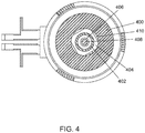
- Figure 4 shows a cross-sectional view of the dual gain solenoid fluid control valve. The view is taken from the position of the dashed line 352 in Figure 3 , although the valve member 314 is not shown.
- the nozzle body 400 surrounds the cylindrical piston wall 402, which is fixed to the rectangular piston base 404.
- a hole 406 in the piston base 404 is sufficiently wide to permit fluid to exit the inner feedback area while the pushpin 408 extends through the hole 406.
- the fluid passes under the piston base 404 and through the opening 410 between the rectangular piston base 404 and the cylindrical nozzle body 400, into the outer feedback chamber.
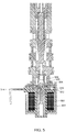
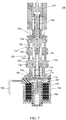
- Figure 6 shows a cross-sectional view of the solenoid fluid control valve taken at the dashed line 514 in Figure 5 .
- fluid travels from an inner to an outer area between the washer and the bobbin and exits through an exhaust port 600.
- the departure of fluid from the outer feedback chamber reduces the pressure in that area, allowing the spool to return to its initial position.
- the dual gain solenoid fluid control valve 300 requires less force from the coil 306 than the direct acting solenoid fluid control valve of Figure 1 requires.
- the force from the coil 306 is only required to displace the valve member 314 from the opening in 318 in the piston 316. Once the valve member 314 is displaced, fluid in the inner feedback chamber 346, 348 and outer feedback chamber 350 provides the force that displaces the spool 220 and compresses the spring mechanism 242.
- the force from the coil 106 in the direct acting solenoid fluid control valve 100 shown in Figure 1 must be sufficient to displace the entire spool 112 and compress the spring mechanism 122. This greater force requires more turns of the coil 106, resulting in a larger, more expensive device.
- the dual gain solenoid fluid control valve utilizes the fluid pressure in the inner and outer feedback chambers to move the spool, thereby requiring fewer turns of the coil, and therefore allowing for a reduction in the device's size and cost.
- the dual gain solenoid fluid control valve has a further advantage of improved robustness to contamination.
- Contamination can greatly affect the performance of a solenoid fluid control valve, as small contaminants in the fluid flowing through the valve may become lodged between moving and stationary elements, obstructing the smooth motion of the armature and spool. This obstruction may lead to hysteresis, as well as to variable responses to a given command current. Accordingly, the presence of contaminants may quickly degrade the solenoid fluid control valve's performance and reliability.
- the first and second feedback chambers of the dual gain solenoid fluid control valve allow fluid to travel through wide passages within the device.
- the fluid may carry contaminants, but the wide chambers allow the valve to function without being inhibited by the contaminants. This increased robustness improves the reliability of the device, allowing for look-up tables to be created relating a current in the coil for a resulting control pressure.
- the lifetime of the device may also be extended as wear due to contaminants is minimized.
- a pulse width modulated (PWM) signal may be used to provide variations in the control pressure.
- the spring cap may be tightened or loosened to adjust the position of the spool in the energized and de-energized states. Once the two positions have been determined, the duty cycle of the PWM signal may determine how much time the solenoid spends in each state, thereby creating a variable control pressure.
- the dual feedback from the inner feedback chamber 846, 848 and outer feedback chambers 850 moves the spool such that the radial spool bore 844 is open to the supply port 832 and the exhaust port 838.
- the calibration cap 840 may be tightened or loosened to adjust the force of the spring mechanism 842 on the spool 820. This force in turn determines the position of the spool 820 when the coil 806 is in the de-energized and energized states. Accordingly, the spool position in the de-energized and energized states may not exactly correspond to the positions shown in Figures 7 and 8 .
- the inner and outer feedback pressure now depends on both the supply and control pressures, and not just the supply pressure. Further, the placement of the radial spool bore 844 allows the device to be configured such that a small control pressure remains even when the coil 806 is energized, and the control pressure it at a minimum. Having a non-zero minimum control pressure allows the valve to be more responsive to a change in the current through the coil. This improved response allows the valve to be more accurately controlled by a PWM signal.
- the dual gain solenoid fluid control valve may be used to control a variable displacement pump, wherein the valve's control pressure regulates the flow of fluid through the pump.
- the pump requires that the valve's response to a given command current be accurate and reliable, so that the command current may be correlated with a flow through the pump.
- the dual gain solenoid fluid control valve provides a reliable control pressure that is robust to contamination and responsive to small changes in the command current.
Landscapes
- Engineering & Computer Science (AREA)
- General Engineering & Computer Science (AREA)
- Mechanical Engineering (AREA)
- Physics & Mathematics (AREA)
- Fluid Mechanics (AREA)
- Magnetically Actuated Valves (AREA)
Claims (18)
- Elektromagnetisches Fluidsteuerventil, umfassend:- ein unbewegliches Magnetspulenelement (302);- ein bewegliches Ankerelement (310);- ein feststehendes Düsengehäuse (322);- einen beweglichen Spulenkörper (320) innerhalb des feststehenden Düsengehäuses, und- ein Ventilelement (314) zur Regulierung von Fluiddruck in einer ersten (346, 348) und zweiten Rückführkammer (350);wobei das unbewegliche Magnetspulenelement einen Kolben (316) enthält, und wobei sich ein Ende des beweglichen Spulenkörpers (320) axial innerhalb eines Bereiches des Kolbens (316) bewegt;
dadurch gekennzeichnet, dass
ein radialer Zwischenraum zwischen einer Innenfläche eines Endes des feststehenden Düsengehäuses und einer Außenfläche des Kolbens (316) die zweite Rückführungskammer (350) einschließt. - Elektromagnetisches Fluidsteuerventil nach Anspruch 1, wobei sich eine Bohrung (344) in dem beweglichen Spulenkörper zu dem inneren Bereich des Kolbens öffnet, um die erste Rückführkammer zu erzeugen.
- Elektromagnetisches Fluidsteuerventil nach Anspruch 1, wobei das feststehende Düsengehäuse mindestens eine Zuführungsöffnung (324) aufweist, und wobei eine Bohrung in dem beweglichen Spulenkörper zulässt, dass Fluid von der mindestens eine Zuführungsöffnung zu der ersten Rückführkammer fließt.
- Elektromagnetisches Fluidsteuerventil nach Anspruch 3, wobei Fluiddrücke in der ersten und zweiten Rückführkammer proportional einem Druck sind, der an der Zuführungsöffnung aufgebaut wird.
- Elektromagnetisches Fluidsteuerventil nach Anspruch 1, wobei Fluid in der ersten Rückführkammer einen ersten Rückführdruck aufbaut.
- Elektromagnetisches Fluidsteuerventil nach Anspruch 5, wobei der erste Rückführdruck auf den beweglichen Spulenkörper mit einer Rückführantriebskraft in einer ersten axialen Richtung wirksam ist.
- Elektromagnetisches Fluidsteuerventil nach Anspruch 6, wobei die Rückführantriebskraft proportional einer axialen Fluidkontaktfläche der ersten Rückführkammer ist.
- Elektromagnetisches Fluidsteuerventil nach Anspruch 7, wobei das elektromagnetische Fluidsteuerventil des Weiteren einen Federmechanismus (342) enthält, wobei der Federmechanismus auf den beweglichen Spulenkörper mit einer Federantriebskraft in einer zweiten axialen Richtung wirksam ist, und wobei die Rückführantriebskraft die Federantriebskraft im Wesentlichen ausgleicht.
- Elektromagnetisches Fluidsteuerventil nach Anspruch 1, wobei das bewegliche Ankerelement ausgelegt ist, das Ventilelement zu verschieben, so dass Fluid von der ersten Rückführkammer zu der zweiten Rückführkammer fließen kann.
- Elektromagnetisches Fluidsteuerventil nach Anspruch 1, wobei Fluid in der zweiten Rückführkammer einen zweiten Rückführdruck aufbaut.
- Elektromagnetisches Fluidsteuerventil nach Anspruch 10, wobei der zweite Rückführdruck auf den beweglichen Spulenkörper mit einer Rückführantriebskraft in einer ersten axialen Richtung wirksam ist.
- Elektromagnetisches Fluidsteuerventil nach Anspruch 11, wobei die Rückführantriebskraft proportional einer axialen Fluidkontaktfläche der zweiten Rückführkammer ist.
- Elektromagnetisches Fluidsteuerventil nach Anspruch 11, wobei der bewegliche Spulenkörper ausgelegt ist, sich als Reaktion auf die Rückführantriebskraft in der axialen Richtung zu bewegen.
- Elektromagnetisches Fluidsteuerventil nach Anspruch 13, wobei das feststehende Düsengehäuse mindestens eine Steueröffnung (332) aufweist, wobei an der Steueröffnung ein Steuerdruck aufgebaut wird, und wobei sich der Steuerdruck bei einem Zustand, in dem sich der bewegliche Spulenkörper in der ersten axialen Richtung bewegt, ändert.
- Elektromagnetisches Fluidsteuerventil nach Anspruch 1, wobei das feststehende Düsengehäuse mindestens eine Steueröffnung aufweist, und wobei eine Bohrung in dem beweglichen Spulenkörper so ausgelegt ist, dass Fluid von der mindestens eine Steueröffnung zu der ersten Rückführkammer fließen kann.
- Elektromagnetisches Fluidsteuerventil nach Anspruch 15, wobei die Fluiddrücke in der ersten und der zweiten Rückführkammer proportional dem Druck sind, der an der Steueröffnung aufgebaut wird.
- Elektromagnetisches Fluidsteuerventil nach Anspruch 16, wobei ein Auslasskanal (338) so ausgelegt ist, dass Fluid die zweite Rückführkammer verlassen kann.
- Elektromagnetisches Fluidsteuerventil nach Anspruch 1, wobei das elektromagnetische Fluidsteuerventil ausgelegt ist, einen Fluidstrom durch eine Verstellpumpe zu steuern.
Applications Claiming Priority (2)
| Application Number | Priority Date | Filing Date | Title |
|---|---|---|---|
| US14/206,442 US9404599B2 (en) | 2014-03-12 | 2014-03-12 | Dual/variable gain oil pump control valve |
| PCT/US2014/031051 WO2015137984A1 (en) | 2014-03-12 | 2014-03-18 | Dual/variable gain oil pump control valve |
Publications (2)
| Publication Number | Publication Date |
|---|---|
| EP3117131A1 EP3117131A1 (de) | 2017-01-18 |
| EP3117131B1 true EP3117131B1 (de) | 2018-01-17 |
Family
ID=50588914
Family Applications (1)
| Application Number | Title | Priority Date | Filing Date |
|---|---|---|---|
| EP14720010.9A Active EP3117131B1 (de) | 2014-03-12 | 2014-03-18 | Steuerventil einer ölpumpe mit doppelter/variabler verstärkung |
Country Status (7)
| Country | Link |
|---|---|
| US (1) | US9404599B2 (de) |
| EP (1) | EP3117131B1 (de) |
| KR (1) | KR101921400B1 (de) |
| CN (1) | CN106104126B (de) |
| CA (1) | CA2942531C (de) |
| ES (1) | ES2661119T3 (de) |
| WO (1) | WO2015137984A1 (de) |
Families Citing this family (17)
| Publication number | Priority date | Publication date | Assignee | Title |
|---|---|---|---|---|
| US8117989B2 (en) | 2008-06-27 | 2012-02-21 | Gea Farm Technologies, Inc. | Milk tube dome with flow controller |
| US10874084B2 (en) | 2004-06-12 | 2020-12-29 | Gea Farm Technologies, Inc. | Safety valve for a dairy system component |
| US11723341B2 (en) | 2009-09-04 | 2023-08-15 | Gea Farm Technologies, Inc. | Safety valve for an automated milker unit backflushing and teat dip applicator system |
| US20120097107A1 (en) | 2010-02-22 | 2012-04-26 | Gea Farm Technologies, Inc. | Dairy animal milking preparation system and methods |
| DE102013114595A1 (de) * | 2013-12-20 | 2015-06-25 | Gea Farm Technologies Gmbh | Sicherheitsventil |
| US9526224B2 (en) | 2013-12-20 | 2016-12-27 | Gea Farm Technologies Gmbh | Safety valve device |
| DE102016108300A1 (de) | 2016-05-04 | 2017-11-09 | Gea Farm Technologies Gmbh | Sicherheitsventil |
| DE102016011059A1 (de) | 2016-09-12 | 2018-03-15 | Thomas Magnete Gmbh | Sitzventil mit elektromagnetischer Betätigung |
| DE102016011058B4 (de) * | 2016-09-12 | 2018-03-29 | Thomas Magnete Gmbh | Sitzventil mit elektromagnetischer Betätigung |
| US11054046B2 (en) | 2016-12-30 | 2021-07-06 | Parker-Hannifin Corporation | Valve with gradual flow area changes |
| JP6949580B2 (ja) * | 2017-06-27 | 2021-10-13 | 日立Astemo株式会社 | 油圧制御装置 |
| JP2019039541A (ja) * | 2017-08-29 | 2019-03-14 | 日本電産トーソク株式会社 | 油圧制御装置 |
| JP2019039542A (ja) * | 2017-08-29 | 2019-03-14 | 日本電産トーソク株式会社 | 油圧制御装置 |
| US10302201B2 (en) | 2017-08-30 | 2019-05-28 | Sun Hydraulics, Llc | Enhancement of valve flow and pressure characteristics in valves and hydraulic systems |
| EP3703489A1 (de) | 2017-11-03 | 2020-09-09 | GEA Farm Technologies, Inc. | Automatisierter zitzentauchflüssigkeitsverteiler |
| JP7007970B2 (ja) * | 2018-03-28 | 2022-01-25 | Kyb株式会社 | 電磁比例制御弁 |
| US11248717B2 (en) | 2019-06-28 | 2022-02-15 | Automatic Switch Company | Modular smart solenoid valve |
Family Cites Families (12)
| Publication number | Priority date | Publication date | Assignee | Title |
|---|---|---|---|---|
| DE2051582A1 (de) * | 1970-10-21 | 1972-07-06 | Schneider Co Optische Werke | Folgekolbenventil |
| US3824898A (en) * | 1972-04-12 | 1974-07-23 | R Pauliukonis | Energy conserving directional valve-cylinder combination |
| US3736958A (en) * | 1972-04-13 | 1973-06-05 | Lockheed Aircraft Corp | Four-way solenoid selector valve |
| JPS5815707Y2 (ja) * | 1976-08-26 | 1983-03-30 | 焼結金属工業株式会社 | パイロット形方向切換弁 |
| GB1530060A (en) | 1976-10-09 | 1978-10-25 | Shoketsu Kinzoku Kogyo Kk | Solenoid pilot operated change-over valve |
| US4199942A (en) * | 1978-09-28 | 1980-04-29 | Eaton Corporation | Load sensing control for hydraulic system |
| DE3221928A1 (de) * | 1982-06-11 | 1983-12-15 | Kienzle Apparate Gmbh, 7730 Villingen-Schwenningen | Elektropneumatische vorsteuerstufe fuer ein pneumatisches servoventil |
| US4526201A (en) * | 1982-11-04 | 1985-07-02 | Spectra-Physics, Inc. | Four-way valve with internal pilot |
| US6343621B1 (en) | 2000-06-30 | 2002-02-05 | Borgwarner Inc. | Variable force solenoid control valve |
| WO2007102912A2 (en) | 2005-12-15 | 2007-09-13 | Parker-Hannifin Corporation | Adjustable pressure control valves |
| US8387644B2 (en) | 2007-02-09 | 2013-03-05 | Saturn Electronics & Engineering, Inc. | Solenoid operated fluid control valve |
| CN201322116Y (zh) * | 2008-08-08 | 2009-10-07 | 宁波市鄞州通力液压电器厂 | 比例减压阀 |
-
2014
- 2014-03-12 US US14/206,442 patent/US9404599B2/en active Active
- 2014-03-18 EP EP14720010.9A patent/EP3117131B1/de active Active
- 2014-03-18 CN CN201480077106.XA patent/CN106104126B/zh active Active
- 2014-03-18 ES ES14720010.9T patent/ES2661119T3/es active Active
- 2014-03-18 WO PCT/US2014/031051 patent/WO2015137984A1/en active Application Filing
- 2014-03-18 KR KR1020167027938A patent/KR101921400B1/ko active IP Right Grant
- 2014-03-18 CA CA2942531A patent/CA2942531C/en active Active
Also Published As
| Publication number | Publication date |
|---|---|
| WO2015137984A1 (en) | 2015-09-17 |
| ES2661119T3 (es) | 2018-03-27 |
| CN106104126B (zh) | 2018-10-19 |
| KR101921400B1 (ko) | 2019-02-13 |
| CA2942531C (en) | 2019-02-19 |
| US20150260302A1 (en) | 2015-09-17 |
| US9404599B2 (en) | 2016-08-02 |
| CN106104126A (zh) | 2016-11-09 |
| CA2942531A1 (en) | 2015-09-17 |
| KR20160130492A (ko) | 2016-11-11 |
| EP3117131A1 (de) | 2017-01-18 |
Similar Documents
| Publication | Publication Date | Title |
|---|---|---|
| EP3117131B1 (de) | Steuerventil einer ölpumpe mit doppelter/variabler verstärkung | |
| US6869060B2 (en) | Hydraulic poppet valve with force feedback | |
| EP2872958B1 (de) | Direkt wirkender elektromagnetaktuator | |
| US8056576B2 (en) | Dual setpoint pressure controlled hydraulic valve | |
| US5571248A (en) | Pressure regulator | |
| EP0451347B1 (de) | Druckregler für Bypassströmung | |
| US9115730B2 (en) | Valve device | |
| US8833729B2 (en) | Proportional throttle valve | |
| US20170159832A1 (en) | Proportional pressure control valve | |
| US8534639B1 (en) | Solenoid valve with a digressively damped armature | |
| WO2020060698A1 (en) | Electrohydraulic normally-open ventable valve configured to operate in pressure relief mode when actuated | |
| US10018269B2 (en) | Normally high acting linear force solenoid | |
| US20130277585A1 (en) | Solenoid valve with a piston damped armature | |
| US8434516B2 (en) | Three position solenoid valve | |
| JP2007051780A (ja) | リリーフバルブ | |
| KR20150091229A (ko) | 래칭 솔레노이드 조절 밸브 | |
| WO2016202635A1 (en) | Axial valve | |
| WO1998053235A1 (fr) | Soupape de regulation de pression proportionnelle | |
| EP1143178A2 (de) | Servolenkung mit variabler Unterstützung und Durchflussregelventil dafür | |
| US8573559B1 (en) | Control valve with area independent pressure sensing | |
| US20070075283A1 (en) | Valve apparatus | |
| US20200025218A1 (en) | Proportional Valve with an Unseater Spring | |
| US9777865B2 (en) | Balanced electronically controlled pressure regulating valve | |
| US20020162592A1 (en) | Solenoid operated, three way, normally closed, high flow, pressure compensated proportional pilot valve | |
| US20150187482A1 (en) | Adjustable center pole |
Legal Events
| Date | Code | Title | Description |
|---|---|---|---|
| PUAI | Public reference made under article 153(3) epc to a published international application that has entered the european phase |
Free format text: ORIGINAL CODE: 0009012 |
|
| 17P | Request for examination filed |
Effective date: 20160913 |
|
| AK | Designated contracting states |
Kind code of ref document: A1 Designated state(s): AL AT BE BG CH CY CZ DE DK EE ES FI FR GB GR HR HU IE IS IT LI LT LU LV MC MK MT NL NO PL PT RO RS SE SI SK SM TR |
|
| AX | Request for extension of the european patent |
Extension state: BA ME |
|
| DAX | Request for extension of the european patent (deleted) | ||
| GRAP | Despatch of communication of intention to grant a patent |
Free format text: ORIGINAL CODE: EPIDOSNIGR1 |
|
| INTG | Intention to grant announced |
Effective date: 20170905 |
|
| GRAS | Grant fee paid |
Free format text: ORIGINAL CODE: EPIDOSNIGR3 |
|
| GRAA | (expected) grant |
Free format text: ORIGINAL CODE: 0009210 |
|
| AK | Designated contracting states |
Kind code of ref document: B1 Designated state(s): AL AT BE BG CH CY CZ DE DK EE ES FI FR GB GR HR HU IE IS IT LI LT LU LV MC MK MT NL NO PL PT RO RS SE SI SK SM TR |
|
| REG | Reference to a national code |
Ref country code: GB Ref legal event code: FG4D |
|
| REG | Reference to a national code |
Ref country code: CH Ref legal event code: EP |
|
| REG | Reference to a national code |
Ref country code: IE Ref legal event code: FG4D |
|
| REG | Reference to a national code |
Ref country code: AT Ref legal event code: REF Ref document number: 964658 Country of ref document: AT Kind code of ref document: T Effective date: 20180215 |
|
| REG | Reference to a national code |
Ref country code: DE Ref legal event code: R096 Ref document number: 602014020033 Country of ref document: DE |
|
| REG | Reference to a national code |
Ref country code: ES Ref legal event code: FG2A Ref document number: 2661119 Country of ref document: ES Kind code of ref document: T3 Effective date: 20180327 |
|
| REG | Reference to a national code |
Ref country code: DE Ref legal event code: R082 Ref document number: 602014020033 Country of ref document: DE Representative=s name: MEISSNER BOLTE PATENTANWAELTE RECHTSANWAELTE P, DE Ref country code: DE Ref legal event code: R081 Ref document number: 602014020033 Country of ref document: DE Owner name: FLEXTRONICS GLOBAL SERVICES CANADA INC., CA Free format text: FORMER OWNER: FLEXTRONICS AUTOMOTIVE INC., MILPITAS, CALIF., US |
|
| RAP2 | Party data changed (patent owner data changed or rights of a patent transferred) |
Owner name: FLEXTRONICS GLOBAL SERVICES CANADA INC. |
|
| REG | Reference to a national code |
Ref country code: NL Ref legal event code: MP Effective date: 20180117 |
|
| REG | Reference to a national code |
Ref country code: LT Ref legal event code: MG4D |
|
| REG | Reference to a national code |
Ref country code: AT Ref legal event code: MK05 Ref document number: 964658 Country of ref document: AT Kind code of ref document: T Effective date: 20180117 |
|
| PG25 | Lapsed in a contracting state [announced via postgrant information from national office to epo] |
Ref country code: NL Free format text: LAPSE BECAUSE OF FAILURE TO SUBMIT A TRANSLATION OF THE DESCRIPTION OR TO PAY THE FEE WITHIN THE PRESCRIBED TIME-LIMIT Effective date: 20180117 |
|
| REG | Reference to a national code |
Ref country code: FR Ref legal event code: PLFP Year of fee payment: 5 |
|
| REG | Reference to a national code |
Ref country code: FR Ref legal event code: TP Owner name: FLEXTRONICS GLOBAL SERVICES CANADA INC., CA Effective date: 20180604 |
|
| PG25 | Lapsed in a contracting state [announced via postgrant information from national office to epo] |
Ref country code: CY Free format text: LAPSE BECAUSE OF FAILURE TO SUBMIT A TRANSLATION OF THE DESCRIPTION OR TO PAY THE FEE WITHIN THE PRESCRIBED TIME-LIMIT Effective date: 20180117 Ref country code: FI Free format text: LAPSE BECAUSE OF FAILURE TO SUBMIT A TRANSLATION OF THE DESCRIPTION OR TO PAY THE FEE WITHIN THE PRESCRIBED TIME-LIMIT Effective date: 20180117 Ref country code: NO Free format text: LAPSE BECAUSE OF FAILURE TO SUBMIT A TRANSLATION OF THE DESCRIPTION OR TO PAY THE FEE WITHIN THE PRESCRIBED TIME-LIMIT Effective date: 20180417 Ref country code: LT Free format text: LAPSE BECAUSE OF FAILURE TO SUBMIT A TRANSLATION OF THE DESCRIPTION OR TO PAY THE FEE WITHIN THE PRESCRIBED TIME-LIMIT Effective date: 20180117 Ref country code: HR Free format text: LAPSE BECAUSE OF FAILURE TO SUBMIT A TRANSLATION OF THE DESCRIPTION OR TO PAY THE FEE WITHIN THE PRESCRIBED TIME-LIMIT Effective date: 20180117 |
|
| PG25 | Lapsed in a contracting state [announced via postgrant information from national office to epo] |
Ref country code: SE Free format text: LAPSE BECAUSE OF FAILURE TO SUBMIT A TRANSLATION OF THE DESCRIPTION OR TO PAY THE FEE WITHIN THE PRESCRIBED TIME-LIMIT Effective date: 20180117 Ref country code: LV Free format text: LAPSE BECAUSE OF FAILURE TO SUBMIT A TRANSLATION OF THE DESCRIPTION OR TO PAY THE FEE WITHIN THE PRESCRIBED TIME-LIMIT Effective date: 20180117 Ref country code: AT Free format text: LAPSE BECAUSE OF FAILURE TO SUBMIT A TRANSLATION OF THE DESCRIPTION OR TO PAY THE FEE WITHIN THE PRESCRIBED TIME-LIMIT Effective date: 20180117 Ref country code: IS Free format text: LAPSE BECAUSE OF FAILURE TO SUBMIT A TRANSLATION OF THE DESCRIPTION OR TO PAY THE FEE WITHIN THE PRESCRIBED TIME-LIMIT Effective date: 20180517 Ref country code: RS Free format text: LAPSE BECAUSE OF FAILURE TO SUBMIT A TRANSLATION OF THE DESCRIPTION OR TO PAY THE FEE WITHIN THE PRESCRIBED TIME-LIMIT Effective date: 20180117 Ref country code: BG Free format text: LAPSE BECAUSE OF FAILURE TO SUBMIT A TRANSLATION OF THE DESCRIPTION OR TO PAY THE FEE WITHIN THE PRESCRIBED TIME-LIMIT Effective date: 20180417 Ref country code: GR Free format text: LAPSE BECAUSE OF FAILURE TO SUBMIT A TRANSLATION OF THE DESCRIPTION OR TO PAY THE FEE WITHIN THE PRESCRIBED TIME-LIMIT Effective date: 20180418 Ref country code: PL Free format text: LAPSE BECAUSE OF FAILURE TO SUBMIT A TRANSLATION OF THE DESCRIPTION OR TO PAY THE FEE WITHIN THE PRESCRIBED TIME-LIMIT Effective date: 20180117 |
|
| REG | Reference to a national code |
Ref country code: DE Ref legal event code: R097 Ref document number: 602014020033 Country of ref document: DE |
|
| PG25 | Lapsed in a contracting state [announced via postgrant information from national office to epo] |
Ref country code: EE Free format text: LAPSE BECAUSE OF FAILURE TO SUBMIT A TRANSLATION OF THE DESCRIPTION OR TO PAY THE FEE WITHIN THE PRESCRIBED TIME-LIMIT Effective date: 20180117 Ref country code: RO Free format text: LAPSE BECAUSE OF FAILURE TO SUBMIT A TRANSLATION OF THE DESCRIPTION OR TO PAY THE FEE WITHIN THE PRESCRIBED TIME-LIMIT Effective date: 20180117 Ref country code: AL Free format text: LAPSE BECAUSE OF FAILURE TO SUBMIT A TRANSLATION OF THE DESCRIPTION OR TO PAY THE FEE WITHIN THE PRESCRIBED TIME-LIMIT Effective date: 20180117 |
|
| REG | Reference to a national code |
Ref country code: CH Ref legal event code: PL |
|
| PLBE | No opposition filed within time limit |
Free format text: ORIGINAL CODE: 0009261 |
|
| STAA | Information on the status of an ep patent application or granted ep patent |
Free format text: STATUS: NO OPPOSITION FILED WITHIN TIME LIMIT |
|
| PG25 | Lapsed in a contracting state [announced via postgrant information from national office to epo] |
Ref country code: SM Free format text: LAPSE BECAUSE OF FAILURE TO SUBMIT A TRANSLATION OF THE DESCRIPTION OR TO PAY THE FEE WITHIN THE PRESCRIBED TIME-LIMIT Effective date: 20180117 Ref country code: DK Free format text: LAPSE BECAUSE OF FAILURE TO SUBMIT A TRANSLATION OF THE DESCRIPTION OR TO PAY THE FEE WITHIN THE PRESCRIBED TIME-LIMIT Effective date: 20180117 Ref country code: MC Free format text: LAPSE BECAUSE OF FAILURE TO SUBMIT A TRANSLATION OF THE DESCRIPTION OR TO PAY THE FEE WITHIN THE PRESCRIBED TIME-LIMIT Effective date: 20180117 Ref country code: SK Free format text: LAPSE BECAUSE OF FAILURE TO SUBMIT A TRANSLATION OF THE DESCRIPTION OR TO PAY THE FEE WITHIN THE PRESCRIBED TIME-LIMIT Effective date: 20180117 Ref country code: CZ Free format text: LAPSE BECAUSE OF FAILURE TO SUBMIT A TRANSLATION OF THE DESCRIPTION OR TO PAY THE FEE WITHIN THE PRESCRIBED TIME-LIMIT Effective date: 20180117 |
|
| REG | Reference to a national code |
Ref country code: BE Ref legal event code: MM Effective date: 20180331 |
|
| 26N | No opposition filed |
Effective date: 20181018 |
|
| REG | Reference to a national code |
Ref country code: IE Ref legal event code: MM4A |
|
| PG25 | Lapsed in a contracting state [announced via postgrant information from national office to epo] |
Ref country code: LU Free format text: LAPSE BECAUSE OF NON-PAYMENT OF DUE FEES Effective date: 20180318 |
|
| PG25 | Lapsed in a contracting state [announced via postgrant information from national office to epo] |
Ref country code: IE Free format text: LAPSE BECAUSE OF NON-PAYMENT OF DUE FEES Effective date: 20180318 |
|
| PG25 | Lapsed in a contracting state [announced via postgrant information from national office to epo] |
Ref country code: SI Free format text: LAPSE BECAUSE OF FAILURE TO SUBMIT A TRANSLATION OF THE DESCRIPTION OR TO PAY THE FEE WITHIN THE PRESCRIBED TIME-LIMIT Effective date: 20180117 Ref country code: BE Free format text: LAPSE BECAUSE OF NON-PAYMENT OF DUE FEES Effective date: 20180331 Ref country code: CH Free format text: LAPSE BECAUSE OF NON-PAYMENT OF DUE FEES Effective date: 20180331 Ref country code: LI Free format text: LAPSE BECAUSE OF NON-PAYMENT OF DUE FEES Effective date: 20180331 |
|
| PG25 | Lapsed in a contracting state [announced via postgrant information from national office to epo] |
Ref country code: MT Free format text: LAPSE BECAUSE OF NON-PAYMENT OF DUE FEES Effective date: 20180318 |
|
| PG25 | Lapsed in a contracting state [announced via postgrant information from national office to epo] |
Ref country code: TR Free format text: LAPSE BECAUSE OF FAILURE TO SUBMIT A TRANSLATION OF THE DESCRIPTION OR TO PAY THE FEE WITHIN THE PRESCRIBED TIME-LIMIT Effective date: 20180117 |
|
| PG25 | Lapsed in a contracting state [announced via postgrant information from national office to epo] |
Ref country code: PT Free format text: LAPSE BECAUSE OF FAILURE TO SUBMIT A TRANSLATION OF THE DESCRIPTION OR TO PAY THE FEE WITHIN THE PRESCRIBED TIME-LIMIT Effective date: 20180117 |
|
| PG25 | Lapsed in a contracting state [announced via postgrant information from national office to epo] |
Ref country code: MK Free format text: LAPSE BECAUSE OF NON-PAYMENT OF DUE FEES Effective date: 20180117 Ref country code: HU Free format text: LAPSE BECAUSE OF FAILURE TO SUBMIT A TRANSLATION OF THE DESCRIPTION OR TO PAY THE FEE WITHIN THE PRESCRIBED TIME-LIMIT; INVALID AB INITIO Effective date: 20140318 |
|
| PGFP | Annual fee paid to national office [announced via postgrant information from national office to epo] |
Ref country code: FR Payment date: 20230323 Year of fee payment: 10 |
|
| PGFP | Annual fee paid to national office [announced via postgrant information from national office to epo] |
Ref country code: IT Payment date: 20230321 Year of fee payment: 10 Ref country code: GB Payment date: 20230321 Year of fee payment: 10 Ref country code: DE Payment date: 20230328 Year of fee payment: 10 |
|
| PGFP | Annual fee paid to national office [announced via postgrant information from national office to epo] |
Ref country code: ES Payment date: 20230424 Year of fee payment: 10 |