EP3116276B1 - Procédé et appareil d'émission de données - Google Patents
Procédé et appareil d'émission de données Download PDFInfo
- Publication number
- EP3116276B1 EP3116276B1 EP14889559.2A EP14889559A EP3116276B1 EP 3116276 B1 EP3116276 B1 EP 3116276B1 EP 14889559 A EP14889559 A EP 14889559A EP 3116276 B1 EP3116276 B1 EP 3116276B1
- Authority
- EP
- European Patent Office
- Prior art keywords
- data transmission
- time
- transmission mode
- data
- domain
- Prior art date
- Legal status (The legal status is an assumption and is not a legal conclusion. Google has not performed a legal analysis and makes no representation as to the accuracy of the status listed.)
- Active
Links
- 230000005540 biological transmission Effects 0.000 title claims description 460
- 238000000034 method Methods 0.000 title claims description 33
- 230000011664 signaling Effects 0.000 claims description 30
- 238000010586 diagram Methods 0.000 description 19
- 238000010295 mobile communication Methods 0.000 description 12
- 238000005516 engineering process Methods 0.000 description 10
- 238000001228 spectrum Methods 0.000 description 8
- 238000001514 detection method Methods 0.000 description 6
- 238000004891 communication Methods 0.000 description 4
- 230000000694 effects Effects 0.000 description 3
- 239000000969 carrier Substances 0.000 description 2
- 125000004122 cyclic group Chemical group 0.000 description 2
- 230000003247 decreasing effect Effects 0.000 description 2
- 230000003111 delayed effect Effects 0.000 description 2
- 230000007774 longterm Effects 0.000 description 2
- 238000013507 mapping Methods 0.000 description 2
- 230000001419 dependent effect Effects 0.000 description 1
- 238000005259 measurement Methods 0.000 description 1
- 238000012986 modification Methods 0.000 description 1
- 230000004048 modification Effects 0.000 description 1
- 210000003205 muscle Anatomy 0.000 description 1
- 230000003287 optical effect Effects 0.000 description 1
- 238000012545 processing Methods 0.000 description 1
- 230000004044 response Effects 0.000 description 1
- 230000008054 signal transmission Effects 0.000 description 1
Images


Classifications
-
- H—ELECTRICITY
- H04—ELECTRIC COMMUNICATION TECHNIQUE
- H04W—WIRELESS COMMUNICATION NETWORKS
- H04W28/00—Network traffic management; Network resource management
- H04W28/16—Central resource management; Negotiation of resources or communication parameters, e.g. negotiating bandwidth or QoS [Quality of Service]
- H04W28/18—Negotiating wireless communication parameters
- H04W28/22—Negotiating communication rate
-
- H—ELECTRICITY
- H04—ELECTRIC COMMUNICATION TECHNIQUE
- H04W—WIRELESS COMMUNICATION NETWORKS
- H04W28/00—Network traffic management; Network resource management
- H04W28/02—Traffic management, e.g. flow control or congestion control
- H04W28/06—Optimizing the usage of the radio link, e.g. header compression, information sizing, discarding information
-
- H—ELECTRICITY
- H04—ELECTRIC COMMUNICATION TECHNIQUE
- H04L—TRANSMISSION OF DIGITAL INFORMATION, e.g. TELEGRAPHIC COMMUNICATION
- H04L5/00—Arrangements affording multiple use of the transmission path
- H04L5/003—Arrangements for allocating sub-channels of the transmission path
- H04L5/0044—Arrangements for allocating sub-channels of the transmission path allocation of payload
-
- H—ELECTRICITY
- H04—ELECTRIC COMMUNICATION TECHNIQUE
- H04L—TRANSMISSION OF DIGITAL INFORMATION, e.g. TELEGRAPHIC COMMUNICATION
- H04L5/00—Arrangements affording multiple use of the transmission path
- H04L5/0091—Signaling for the administration of the divided path
-
- H—ELECTRICITY
- H04—ELECTRIC COMMUNICATION TECHNIQUE
- H04L—TRANSMISSION OF DIGITAL INFORMATION, e.g. TELEGRAPHIC COMMUNICATION
- H04L27/00—Modulated-carrier systems
- H04L27/26—Systems using multi-frequency codes
- H04L27/2601—Multicarrier modulation systems
-
- H—ELECTRICITY
- H04—ELECTRIC COMMUNICATION TECHNIQUE
- H04L—TRANSMISSION OF DIGITAL INFORMATION, e.g. TELEGRAPHIC COMMUNICATION
- H04L5/00—Arrangements affording multiple use of the transmission path
- H04L5/003—Arrangements for allocating sub-channels of the transmission path
- H04L5/0053—Allocation of signaling, i.e. of overhead other than pilot signals
Definitions
- the present invention relates to a mobile communication technology, in particular to a dynamic data transmission method and apparatus based on a time-domain symbol.
- next generation mobile communication technology i.e., the 5th Generation (5G) mobile communication technology.
- 5G next generation mobile communication technology
- the industry generally believes that the next generation mobile communication system should have features such as ultrahigh speed, ultrahigh capacity, ultrahigh reliability and ultralow delay transmission feature.
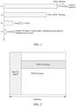
- FIG. 1 is a schematic diagram of delay transmission features in existing different generation mobile communication technologies.
- horizontal ordinates express delay demands and longitudinal coordinates express different generation mobile communication systems.
- a delay of data transmission in a traditional system of the 2nd Generation (2G) mobile communication technology exceeds 100ms, and this delay can reach a low delay communication effect in the aspect of human body muscle response;
- a delay of data transmission in a system of the 3rd Generation (3G) mobile communication technology is 100ms, and this delay can reach a low delay communication effect in the aspect of hearing;
- a delay of data transmission in a 4G system is about 20ms, and this delay can reach a low delay communication effect in the aspect of vision.
- a physical downlink control channel is located on first n Orthogonal Frequency Division Multiplexing (OFDM) symbols of a sub frame, and a Physical Downlink Share Channel (PDSCH) is located after a Physical Downlink Control Channel (PDCCH) time domain and occupies the entire subframe in the time domain.
- OFDM Orthogonal Frequency Division Multiplexing
- PDSCH Physical Downlink Share Channel
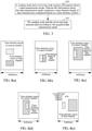
- an enhanced Physical Downlink Control Channel (ePDCCH) and a physical downlink share channel use a frequency division multiplexing mode, and time-domain lengths are the same, as illustrated in FIG. 2 which is a schematic diagram of a physical downlink control channel and a physical downlink share channel in an existing LTE system.
- an oblique line shaded part expresses a PDCCH region
- an oblique small check shaded part expresses an ePDCCH region
- a black part expresses a PDSCH region.
- a PDSCH frequency-domain position can be known and corresponding data decoding is started to implement data transmission.
- the PDCCH/ePDCCH receiving is delayed, thus decoding of data born by the PHSCH will be delayed; and in the other aspect, since an interval of PDCCH/ePDCCH/PDSCH transmission in the LTE system is one subframe, even though there is burst super real-time data transmission, processing can be performed by waiting for the incoming of a next subframe and this data transmission mode increases data transmission delay.
- time-domain length is fixed, i.e., the entire subframe is occupied in time domain
- a frequency-domain position of data transmission can only be adjusted.
- data transmission can only be completed in a delay of one subframe, this undoubtedly also increases data transmission delay and consequently rapid transmission of data is hindered.
- the document US2010/0284339 discloses a method of transmitting cyclic prefix length information when wireless access systems having different cyclic prefix lengths coexist.
- the document US 2008/279143 A1 discloses a method for supporting short latency data transmission in a mobile communication system.
- the embodiments of the present invention provide a data transmission method and apparatus, which can decrease data transmission delay, satisfy transmission delay requirements under specific application scenarios and thus realize rapid transmission of data.
- the time-domain length of data transmission is configured based on the time-domain symbol
- the setting of the time-domain length of data transmission is flexible
- multiple opportunities of data transmission can exist in one subframe
- resources used for data transmission can be guaranteed to be found rapidly when there is a data transmission demand, thus rapid data transmission is realized and data transmission delay is reduced.
- FIG. 3 is a flowchart of a data transmission method according to the embodiment of the present invention. As illustrated in FIG. 3 , the data transmission method includes the following steps:
- a transmission node acquires information about a data transmission mode, and the information about the data transmission mode includes a rapid data transmission mode, the rapid data transmission mode includes a time-domain length of data transmission configured based a time-domain symbol.
- the transmission node includes a sending node and a receiving node. It needs to be stated that, for transmission networks such as some private networks or dedicated networks in which sending nodes only supporting the rapid data transmission mode are located, all receiving nodes accessing to the transmission networks use the rapid data transmission mode to transmit data.
- acquiring the information about the data transmission mode includes:
- the time-domain symbol at least includes: an Orthogonal Frequency Division Multiplexing (OFDM) symbol, or a Single Carrier Frequency Division Multiple Access (SC-FDMA) symbol,
- OFDM Orthogonal Frequency Division Multiplexing
- SC-FDMA Single Carrier Frequency Division Multiple Access
- the time-domain length includes h time-domain symbols.
- h includes at least one of 1, 2, 3 or 4, and the number of time-domain symbols contained in one or more subframes mainly involves in an application scenario that the time-domain length of one or more subframes is less than 1ms; or the situation of dividing into a plurality of small data packets needs to be avoided so as to realize transmission of larger data packets.
- the sub frame with a length less than 1ms is a sub frame in a frame structure newly defined in the embodiment of the present invention and is different from the defined subframe in the frame structure of the existing LTE system; and the time-domain length according to the claims is one of a plurality of preset lengths , 1, 2, 3 or 4 symbols, and is dynamically selected through signaling .
- time-domain length of data transmission in the embodiment of the present invention, multiple opportunities of data transmission can exist within 1ms, resources used for data transmission can be guaranteed to be found rapidly when there is a data transmission demand, and thus rapid data transmission is realized.
- the number of the time-domain symbols for transmitting data in the time-domain length is dynamically determined according to information of data which needs to be transmitted such as a size of a data packet, such that the data can be guaranteed to be completely transmitted within a time as short as possible, and the problem of time delay caused by dividing one data packet into a plurality of small data packets for transmission since the time-domain length of data transmission is limited is avoided.
- a determining mode of a time-domain region of the time-domain symbols in the subframe is:
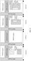
- a relationship between the data channel and a corresponding control channel is that: in a first relationship, time-domain symbols of the data channel and time-domain symbols of the corresponding control channel have the same time-domain starting position and time-domain ending position, as illustrated in FIG. 4(a) ; or in a second relationship, a time-domain starting position of time-domain symbols of the data channel is next to a time-domain ending position of time-domain symbols of its corresponding control channel as illustrated in FIG.
- the data channel and its corresponding control channel have the same frequency-domain positions, or have different or partially same frequency-domain positions; optionally, if the data channel and its corresponding control channel agree to have the same frequency-domain positions, the frequency-domain positions of the data channel do not need to be indicated by signaling and the frequency-domain positions of the data channel may be determined according to the detected control channel; or the frequency-domain positions of the data channel and its corresponding control channel are respectively determined, and the frequency-domain positions of the data channel may be determined through resource indication signaling born by the control channel; or in a third relationship, time-domain symbols of the data channel and time-domain symbols of its corresponding control channel have the same time-domain starting position and a time-domain length of the data channel is greater than or equal to a time-domain length of the control channels, as illustrated in FIG.
- the time-domain length of the data channel may be preset, or indicated by signaling from the sending node (i.e., the sending node transmits a data channel time-domain length signaling indication to the receiving node, and after the receiving node receives the signaling indication, the receiving node determines the time-domain length of the data channel according to the signaling indication) or determined according to the time-domain length of the control channel, e.g., the time-domain length of the data channel is k times of the time-domain length of the control channel, and k is 1, 2, 3, 4, etc., or the time-domain length of the data channel and the time-domain length of the control channel have a preset mapping relationship, as shown in Table 1 and Table 2; at this moment, the frequency-domain positions of the data channel and its corresponding control channel are not strictly limited, i.e., may be the same and may also be different; Table 1 Time-domain length of control channel 1 2 3 4 Time-domain length of data channel 2 3 5 6 or as shown in
- Indicating the time-domain length of the data channel through the signaling includes: the sending node transmitting data channel time-domain length indication signaling to the receiving node, and after the receiving node receives the signaling, determining the time-domain length of the data channel according to the signaling, herein the signaling may represent a length value, and several values may also be preset and the value is dynamically selected according to the signaling; or
- Frequency-domain positions of the data channel and its corresponding control channel may be discontinuous and may also be continuous, and specific implementation thereof does not limit the protection range of the present invention.
- the data channel and its corresponding control channel include: a downlink data channel and its corresponding downlink control channel, and/or a uplink data channel and its corresponding uplink control channel, and, the uplink control channel is used for bearing uplink control information, such as Hybrid Automatic Repeat reQuest Acknowledgment (HARQ-ACK), and Channel State Information (CSI); and the time-domain length of the uplink control channel is also allocated based on the time-domain symbols.
- uplink control information such as Hybrid Automatic Repeat reQuest Acknowledgment (HARQ-ACK), and Channel State Information (CSI)
- CSI Channel State Information
- the uplink control channel may be used for indicating related transmission information of the corresponding data channel, e.g., a size of a transmission block, a new data packet/old data packet, version information, related reference signal information, etc.
- autonomous scheduling refers to pre-allocating partial sources, e.g., PUSCH resources or resources for transmitting data with a new time-frequency unit as a unit.
- the receiving node when the receiving node has a data transmission demand, the receiving node directly transmits data on the predefined resources and does not need to send a scheduling request to the sending node to wait for the scheduling by the sending node, such that the delay caused by waiting for scheduling is decreased, the data transmission delay is shortened and thus the data transmission speed is improved.
- the resources of the control channel are mapped by using a preset mode, e.g., locating on preset time-domain resources, data transmission is performed according to the preset size of the transmission block, and a fixed modulating and coding mode is used, including: a frequency domain is continuously or discretely mapped by taking a resource block as a unit or is continuously or discretely mapped by taking a specific control channel unit; the control channel and the data channel may be multiplexed on a same resource block of a same time-domain symbol, or multiplexed on different time-domain symbols of a same resource block, or multiplexed on different resource blocks of a same time-domain symbol.
- a preset mode e.g., locating on preset time-domain resources
- data transmission is performed according to the preset size of the transmission block
- a fixed modulating and coding mode is used, including: a frequency domain is continuously or discretely mapped by taking a resource block as a unit or is continuously or discretely mapped by taking
- step 301 the sending node and the receiving node transmit data according to the acquired data transmission mode.
- transmitting the data according to the data transmission mode includes: transmitting uplink data and its corresponding control channel according to the data transmission mode, and/or transmitting downlink data and its corresponding control channel according to the data transmission mode, i.e., data transmission is performed according to time-frequency resources designated in the data transmission mode.
- Transmission includes sending and/or receiving.
- the uplink data are born through the uplink data channel
- uplink control information is born through the uplink control channel
- the uplink control information includes feedback information of downlink data, and/or channel state information, and/or transmission information related to uplink data, etc.
- the transmitted data include a size of a transmission block, and/or a new data packet/old data packet, and/or version information, and/or a modulating mode, and/or related reference signal information.
- the sending node receives uplink data and its corresponding control channel and/or sending downlink data and its corresponding control channel according to the configuration of the data channel and the control channel in the embodiment of the present invention, and the sending node includes but not limited to a base station, a relay transmission node, a wireless gateway or a router; and the receiving node receives downlink data and/or sends uplink data according to the configuration of the data channel and the control channel in the present invention, and the receiving node includes but not limited to User Equipment (UE), a micro base station or a home base station.
- UE User Equipment
- FIG. 5 is a schematic diagram of data transmission in a rapid data transmission mode under a spectrum share scenario according to the embodiment of the present invention.
- FIG. 5 is a schematic diagram of data transmission in a rapid data transmission mode under a spectrum share scenario according to the embodiment of the present invention.
- idle resources may be partial uplink resources which are caused to be idle due to uplink and downlink service asymmetry such that the idle uplink resources are used for transmitting downlink data, or partial downlink resources are idle such that the idle downlink resources are used for transmitting uplink data, or when the LTE system and other systems share spectrum resources and the other systems do not use the resources, the LTE system may use the idle resources to transmit uplink data or downlink data.
- the method further includes dividing data transmission opportunities, including: continuously dividing data transmission opportunities or dividing data transmission opportunities according to a preset interval, and, continuous dividing data transmission opportunities includes: numbering all time-domain symbols available for data transmission in a preset specific time window, and sequentially setting apart every h time-time symbols into a time-domain unit, herein the time-domain unit is used for data transmission.
- supposing that the number of time-domain symbols available for data transmission within 1ms is 11, if h is 2, 6 time-domain units can be set and the last time-domain unit includes one time-domain symbol; or 5 time-domain units are set apart and the last time-domain unit includes 3 time-domain symbols.
- supposing that the number of time-domain symbols available for data transmission within 3ms is 33, if h is 3, 11 time-domain units can be set apart.
- supposing that the number of time-domain symbols available for data transmission in 2ms is 20, if h is 4, 5 time-domain units can be set apart, etc.
- Dividing data transmission opportunities according to the preset interval includes: supposing that k data transmission opportunities exist in a specific time window, herein k is a preset value, and using remaining other time-domain symbols for other purposes, e.g., control channel transmission, reference signal transmission, synchronizing channel or broadcast channel or multicast channel transmission, etc., herein reference signals may be used for measurement and may also be used for demodulation.
- the specific time window mainly limits the time-domain region used for transmitting the data channel.
- the time-domain length of data transmission is configured based on the time-domain symbol
- the setting of the time-domain length of data transmission is flexible
- multiple opportunities of data transmission can exist in one subframe
- resources used for data transmission can be guaranteed to be found rapidly when there is a data transmission demand, thus rapid data transmission is realized and data transmission delay is reduced.
- the demands of data scheduling for time-domain resources are reduced, more flexible resource application is realized and spectrum efficiency is improved.
- the method further includes: the sending node determining whether the receiving node uses the rapid data transmission mode, including: the sending node determining whether the receiving node uses the rapid data transmission mode according to preset transmission information of the receiving node, and when determining that the receiving node uses the rapid data transmission mode, sending the information about the data transmission information to the receiving node to indicate that the data transmission mode of the receiving node is the rapid data transmission mode.
- the preset transmission information of the receiving node at least includes at least one of the following: transmission mode request information, device type information and service type information.
- Determining whether the receiving node uses the rapid data transmission mode includes:
- the sending node determines that the receiving node transmits data according to the conventional data transmission mode.
- the sending node further judges the current service demand, such as Quality of service (Qos) and service type, and determines whether the receiving node uses the rapid data transmission mode; or the sending node determines whether the receiving node uses the rapid data transmission mode according to the transmission mode request information received from the receiving node having the ultralow delay data transmission demand, and if the transmission mode request information is not received from the receiving node, the receiving node uses the conventional data transmission mode to transmit data.
- Qos Quality of service
- service type service type
- the method provided by the embodiment of the present invention further includes: the sending node setting the receiving node to simultaneously use the rapid data transmission mode and the conventional data transmission mode, herein the rapid data transmission mode and the conventional data transmission mode of the receiving node are located in different serving cells (the serving cells may also be viewed as component carriers), or are located on different subframes of a same serving cell, or are located on different time-domain symbols of a same subframe of a same serving cell.
- a primary serving cell uses the conventional data transmission mode
- a secondary serving cell uses the rapid data transmission mode
- the configuration mode of the data transmission mode of the embodiment of the present invention may use a combination of a plurality of modes, e.g., a combination of a subframe configuration mode and a configuration mode based on a serving cell, or a combination of a configuration mode of different time-domain symbols in a subframe and a configuration mode based on a serving cell, or a combination of a subframe configuration mode, a configuration mode based on a serving cell, and a configuration mode of different time-domain symbols in a subframe, etc., which is not limited here.
- One or more relationships may exist between the control channel and the data channel, e.g., different resources select different modes, or different service types select different modes, or different terminals select different modes, or different transmission nodes select different modes, or different configurations are performed aiming at a plurality of different resource selections, service types, terminals and transmission nodes, etc.
- a sending node is a relay transmission node and a receiving node is user equipment.
- the relay transmission node in this embodiment determines that the user equipment supports a rapid data transmission mode, data are transmitted between the relay transmission node and the user equipment according to the rapid data transmission mode, and the rapid data transmission mode includes: a time-domain length of data transmission is configured based on a time-domain symbol.
- the relay transmission node is a transmission node which only supports the rapid data transmission mode, all user equipment accessing to the relay transmission node use the rapid data transmission mode to transmit data; and at this moment, a mode configuration does not need to be sent to the user equipment and the user equipment accessing to the relay transmission node can recognize that the rapid data transmission mode needs to be used to perform data transmission.
- the relay transmission node needs to determine whether the accessing user equipment supports the rapid data transmission mode according to predefined transmission information of the user equipment, and the predefined transmission information at least includes at least one of the following: transmission mode request information, user equipment type and service information, and the transmission mode request information is sent by the user equipment; the user equipment type includes user equipment having an ultralow delay data transmission demand; and the service type includes an ultralow delay service, data demanded by a small resource block, etc., e.g., ultrasonic delay demand services of 1ms, 20ms, etc.
- the relay transmission node further judges the current service demand, such as Quality of service (Qos) and service type, and determines whether the user equipment uses the rapid data transmission mode; or the relay transmission node determines whether the user equipment uses the rapid data transmission mode according to the transmission mode request information received from the user equipment having the ultralow delay data transmission demand, and if the transmission mode request information is not received from the user equipment, the user equipment uses the conventional data transmission mode to transmit data; and thereafter, the relay transmission node sends transmission mode configuration information to the user equipment to indicate that the transmission mode of the user equipment is the rapid data transmission mode.
- Qos Quality of service
- service type service type
- the time-domain symbol includes at least one of the following: an Orthogonal Frequency Division Multiplexing (OFDM) symbol, a Single Carrier Frequency Division Multiple Access (SC-FDMA) symbol; and the time-domain length includes h time-domain symbols, and according to the claims h includes at least one of 1, 2, 3 or 4.
- OFDM Orthogonal Frequency Division Multiplexing
- SC-FDMA Single Carrier Frequency Division Multiple Access
- the time-domain length of the data channel is dynamically changed.
- a relationship between the data channel and a corresponding control channel includes at least one of the following:
- the frequency-domain position of the data channel is indicated by information born by the corresponding control channel; or the frequency-domain position is determined according to the frequency-domain position of the corresponding control channel, e.g., they are the same frequency-domain positions or have a specific mapping relationship, e.g., the control channel is located on frequency-domain position X, the data channel is located on frequency-domain position 2 ⁇ X or (X+1), etc.; or the position of the data channel is preconfigured by a base station, etc.
- transmitting the data according to the rapid data transmission mode includes: the relay transmission node receiving uplink data and its corresponding control channel according to the rapid data transmission mode, and/or sending downlink data and its corresponding control channel according to the rapid data transmission mode; and the user equipment receiving downlink data and/or sending uplink data according to the configurations of the data channel and the control channel.
- the relay transmission node receives the uplink data and the corresponding uplink control information sent by the user equipment, and the uplink data are born through the uplink data channel, and the uplink control information is born through the uplink control channel; and the uplink control information includes at least one of the following: feedback information of downlink data, downlink channel state information and transmission information related to the uplink data.
- the transmission information transmitted through the rapid data transmission mode includes at least one of the following: a size of a transmission block, a new data packet/old data packet, version information, a modulating mode and related reference signal information; the base station firstly decodes the control channel to acquire the transmission information, and then decodes the data channel according to the transmission information.
- the data channel when the data channel is an uplink data channel, the data channel may not have a corresponding control channel, and data transmission is performed in a predefined format according to resources pre-allocated by the base station and the service demand of the user equipment, e.g., code modulation and sending are performed according to the transmission block with the predetermined size, and whether data repeat is performed is determined according to feedback information for the base station sending data to the user equipment.
- the relay transmission node configures that the user equipment simultaneously supports the rapid data transmission mode and the conventional data transmission mode
- the rapid data transmission mode and the conventional data transmission mode of the receiving node are located on different component carriers (serving cells), or are located on different subframes of a same component carrier (serving cell) or different time-domain symbols of a same subframe.
- a primary serving cell uses the conventional data transmission mode, and a secondary serving cell uses the rapid data transmission mode;
- User equipment determines whether to transmit data according to a rapid data transmission mode according to predefined transmission information, and the rapid data transmission mode includes: a time-domain length of data transmission is configured based on a time-domain symbol.
- the predefined transmission information at least includes at least one of the following: configuration information, access system (transmission node) type and service information;
- the access system type includes the system supporting the rapid data transmission mode;
- the configuration information is configuration information sent by the transmission node;
- the service type includes an ultralow delay service and data demanded by a small resource block, e.g., an ultralow delay demand service of 1ms, 20ms, etc.
- the user equipment may determine whether to transmit data according to the rapid data transmission mode as follows:
- the embodiment of the present invention further provides a data transmission system, at least including a transmission node, the transmission node is configured to acquire information about a data transmission mode and transmit data according to the acquired data transmission mode, herein the information about the data transmission mode includes a rapid data transmission mode, the rapid data transmission mode includes: configuring a time-domain length of data transmission based on a time-domain symbol.
- the transmission node includes a sending node and/or a receiving node, and the sending node is configured to acquire information about a data transmission mode and transmit data according to the acquired data transmission mode; and the receiving node is configured to acquire the information about the data transmission mode and transmit data according to the acquired data transmission mode, herein the information about the data transmission mode includes a rapid data transmission mode, the rapid data transmission mode includes a time-domain length of data transmission configured based a time-domain symbol.
- the sending node only supports the rapid data transmission mode.
- the sending node When the sending node not only supports the rapid data transmission mode, but also supports a conventional data transmission mode, the sending node is further configured to determine whether the receiving node supports the rapid data transmission mode according to preset transmission information of the receiving node, and when determining that the receiving node supports the rapid data transmission mode, send the information about the data transmission mode to the receiving node to indicate that the data transmission mode of the receiving node is the rapid data transmission mode, herein the preset transmission information of the receiving node at least includes at least one of the following: transmission mode request information, device type information and service type information.
- the receiving node is further configured to transmit data by using the rapid data transmission mode according to the indication of the sending node.
- the sending node is further configured to, when determining that the receiving node does not support the rapid data transmission mode, determine that the receiving node transmits data according to the conventional data transmission mode; and correspondingly, the receiving node is further configured to transmit data by using the conventional data transmission mode according to the indication of the sending node.
- the sending node is further configured to, when determining that the receiving node simultaneously supports the rapid data transmission mode and the conventional data transmission mode, set the receiving node to simultaneously support the rapid data transmission mode and the conventional data transmission mode; and correspondingly, the receiving node is further configured to perform data transmission in the rapid data transmission mode and/or the conventional data transmission mode according to the setting of the sending node.
- the sending node includes, but not limited to, a base station, a relay transmission node, a wireless gateway or a router; and the receiving node includes, but not limited to user equipment, a micro base station or a home base station.
- the present invention further provides data transmission software, which is used for executing the above-mentioned embodiments and the technical solutions described in the preferred embodiments.
- the present invention further provides a storage medium, which stores the above-mentioned software and includes, but not limited to, an optical disk, a soft disk, a hard disk, an erasable memory, etc.
- modules and all steps in the present invention may be implemented by using general-purpose computing devices, and they may be integrated in a single computing device or distributed on a network consisting of a plurality of computing devices. Alternatively they may be implemented by using program codes executable by computing devices, and thus they may be stored in memory devices and executed by computing devices, or they may be respectively manufactured into integrated circuit modules, or a plurality of modules or steps thereof may be manufactured into a single integrated circuit module to implement. Therefore, the present invention is not limited to any specific combination of hardware and software.
- the embodiments of the present invention can reduce data transmission delay, satisfy transmission delay requirements under specific application scenarios and thus realize rapid data transmission.
Landscapes
- Engineering & Computer Science (AREA)
- Signal Processing (AREA)
- Computer Networks & Wireless Communication (AREA)
- Quality & Reliability (AREA)
- Mobile Radio Communication Systems (AREA)
Claims (28)
- Procédé de transmission de données, comprenant :
un nœud de transmission acquérant des informations relatives à un mode de transmission de données (300), lesdites informations relatives au mode de transmission de données comprenant un mode de transmission rapide de données, ledit mode de transmission rapide de données comprenant : la configuration d'une longueur de domaine temporel de transmission de données, ladite longueur de domaine temporel comprenant un nombre de symboles de domaine temporel, et le symbole de domaine temporel comprenant : un symbole de multiplexage par répartition orthogonale de la fréquence, OFDM, ou un symbole d'accès multiple par répartition en fréquence à porteuse unique, SC-FDMA ; et le nœud de transmission transmettant des données conformément au mode de transmission de données (301) acquis, le nombre de symboles de domaine temporel étant modifié dynamiquement par signalement généré par un canal de commande correspondant à un canal de données, et le nombre de symboles de domaine temporel comprenant 1 et/ou 2 et/ou 3 et/ou 4. - Procédé de transmission de données selon la revendication 1, où le nœud de transmission comprend un nœud d'émission et où le nœud d'émission n'assiste que le mode de transmission rapide de données.
- Procédé de transmission de données selon la revendication 1, où le nœud de transmission comprend un nœud d'émission et un nœud de réception, et où, si le nœud d'émission assiste non seulement le mode de transmission rapide de données, mais aussi un mode de transmission de données conventionnel, ledit procédé comprend en outre :la détermination par le nœud d'émission si le nœud de réception recourt au mode de transmission rapide de données ; et,lorsqu'il est déterminé que le nœud de réception recourt au mode de transmission rapide de données, l'envoi des informations relatives au mode de transmission de données vers le nœud de réception pour indiquer que le mode de transmission de données du nœud de réception est le mode de transmission rapide de données.
- Procédé de transmission de données selon la revendication 3, où la détermination si le nœud de réception recourt au mode de transmission rapide de données comprend :
la détermination si le nœud de réception recourt au mode de transmission rapide de données conformément aux informations de transmission prédéfinies du nœud de réception. - Procédé de transmission de données selon la revendication 4, où les informations de transmission prédéfinies du nœud de réception comprennent au moins une des sortes d'informations suivantes informations de demande de mode de transmission, informations de type de dispositif et informations de type de service.
- Procédé de transmission de données selon la revendication 4, où la détermination si le nœud de réception recourt au mode de transmission rapide de données comprend :si le nœud d'émission reçoit des informations de demande de mode de transmission du nœud de réception, la détermination par le nœud d'émission que le nœud de réception recourt au mode de transmission rapide de données ; ousi le nœud d'émission détermine qu'un type du nœud de réception est un dispositif assistant une transmission rapide de données conformément aux informations de type de dispositif du nœud de réception, la détermination par le nœud d'émission que le nœud de réception recourt au mode de transmission rapide de données ; ousi le nœud d'émission détermine qu'un type de service du nœud de réception comprend un service à très faible retard et/ou des données demandées par un bloc de ressources limitées conformément aux informations de type de services du nœud de réception, la détermination par le nœud d'émission que le nœud de réception recourt au mode de transmission rapide de données ; ousi le nœud d'émission détermine qu'un dispositif de réception est un dispositif assistant une transmission rapide de données conformément aux informations de type de dispositif du nœud de réception et détermine que le dispositif de réception est d'un type de service recourant à une transmission rapide de données conformément à un type de service du dispositif de réception, la détermination par le nœud d'émission que le nœud de réception recourt au mode de transmission rapide de données.
- Procédé de transmission de données selon la revendication 1 ou la revendication 3, où le nœud de transmission comprend un nœud d'émission et un nœud de réception, et où, si le nœud d'émission détermine que le nœud de réception recourt simultanément au mode de transmission rapide de données et au mode de transmission de données conventionnel, ledit procédé comprend en outre : le paramétrage du nœud de réception par le nœud d'émission pour recourir simultanément au mode de transmission rapide de données et au mode de transmission de données conventionnel.
- Procédé de transmission de données selon la revendication 7, où le mode de transmission rapide de données et le mode de transmission de données conventionnel du nœud de réception sont localisé dans des cellules de desserte différentes, ou sont localisés sur des sous-trames différentes d'une même cellule de desserte, ou sont localisés sur des symboles de domaine temporel différents d'une même sous-trame d'une même cellule de desserte.
- Procédé de transmission de données selon la revendication 8, où, si le nœud de réception assiste simultanément le mode de transmission rapide de données et le mode de transmission de données conventionnel, ledit procédé comprend au moins un des éléments suivants :une cellule de desserte primaire du nœud de réception recourant au mode de transmission de données conventionnel, et une cellule de desserte secondaire du nœud de réception recourant au mode de transmission rapide de données ;la cellule de desserte primaire du nœud de réception recourant au mode de transmission de données conventionnel et une cellule de desserte dédiée du nœud de réception recourant au mode de transmission rapide de données ;différents ensembles de sous-trames d'une même cellule de desserte du nœud de réception recourant à différents modes de transmission ; etdifférents symboles de domaine temporel d'une même sous-trame d'une même cellule de desserte du nœud de réception recourant à différents modes de transmission.
- Procédé de transmission de données selon la revendication 1, la revendication 2 ou la revendication 3, où le nœud de transmission comprend un nœud d'émission et un nœud de réception ; et où l'acquisition d'informations relatives à un mode de transmission de données comprend :l'envoi par un nœud supérieur dans un réseau de transmission des informations relatives au mode de transmission de données au nœud d'émission avant la transmission de données, et l'envoi par le nœud d'émission des informations relatives au mode de transmission de données au nœud de réception ; oul'envoi par le nœud d'émission des informations relatives au mode de transmission de données au nœud de réception avant l'envoi par le nœud d'émission de données si le nœud de réception nécessite d'effectuer une transmission de données ; oul'envoi par le nœud d'émission des informations relatives au mode de transmission de données dans des informations de commande correspondant à des données si le nœud de réception nécessite d'effectuer une transmission de données ; oula détermination dynamique des informations relatives au mode de transmission de données conformément à des informations de données nécessitant d'être transmises si une transmission de données est effectuée entre le nœud d'émission et le nœud de réception.
- Procédé de transmission de données selon la revendication 1, où un mode de détermination d'une plage de domaine temporel des symboles de domaine temporel dans une sous-trame est la détermination d'une position initiale de domaine temporel des symboles de domaine temporel conformément à une position initiale de domaine temporel d'un canal de commande relatif aux données, et où une relation entre un canal de données et un canal de commande correspondant est que :
des positions de domaine temporel de symboles de domaine temporel du canal de données sont déterminées conformément au signalement généré par le canal de commande correspondant au canal de données, et une position initiale de domaine temporel de symboles de domaine temporel du canal de données précède ou suit, ou est identique à une position initiale de domaine temporel de symboles de domaine temporel du canal de commande ; ou une position initiale de domaine temporel de symboles de domaine temporel du canal de données est définie conformément à une longueur de domaine temporel du canal de données, et une plage de symbole de domaine temporel du canal de commande est située sur une position prédéfinie dans une plage de longueur de domaine temporel du canal de données. - Procédé de transmission de données selon la revendication 1, où le nombre de symboles de domaine temporel pour la transmission de données est prédéfini ; ou le nombre de symboles de domaine temporel est déterminé dynamiquement conformément aux informations de données nécessitant d'être transmises.
- Procédé de transmission de données selon la revendication 1, où le canal de données et le canal de commande correspondant du canal de données comprennent : un canal de données de liaison descendante et un canal de commande de liaison descendante correspondant du canal de données de liaison descendante, et/ou un canal de données de liaison montante et un canal de commande de liaison montante correspondant du canal de données de liaison montante ; et
si le canal de données de liaison montante recourt à une programmation autonome, le canal de commande de liaison montante est utilisé pour indiquer des informations de transmission relatives du canal de données correspondant. - Procédé de transmission de données selon la revendication 1, la revendication 2 ou la revendication 3, où la transmission des données conformément au mode de transmission de données comprend :
la transmission de données de liaison montante et d'un canal de commande correspondant des données de liaison montante conformément au mode de transmission de données, et/ou la transmission de données de liaison descendante et d'un canal de commande correspondant des données de liaison descendante conformément au mode de transmission de données, les données de liaison montante étant générées par un canal de données de liaison montante, les informations de commande de liaison montante étant générées par un canal de commande de liaison montante et la transmission comprenant l'émission et/ou la réception. - Procédé de transmission de données selon la revendication 1, la revendication 2 ou la revendication 3, où le nœud d'émission comprend une station de base, un nœud de transmission par relais, une passerelle sans fil ou un routeur ; et le nœud de réception comprend un équipement utilisateur, une microstation de base ou une station de base domestique.
- Nœud d'émission prévu pour acquérir des informations relatives à un mode de transmission de données et transmettre des données conformément au mode de transmission de données acquis, où les informations relatives au mode de transmission de données comprennent un mode de transmission rapide de données, ledit mode de transmission rapide de données comprenant : la configuration d'une longueur de domaine temporel de transmission de données, ladite longueur de domaine temporel comprenant un nombre de symboles de domaine temporel, et le symbole de domaine temporel comprenant : un symbole de multiplexage par répartition orthogonale de la fréquence, OFDM, ou un symbole d'accès multiple par répartition en fréquence à porteuse unique, SC-FDMA,
où le nombre de symboles de domaine temporel est modifié dynamiquement par signalement généré par un canal de commande correspondant à un canal de données, et le nombre de symboles de domaine temporel comprend 1 et/ou 2 et/ou 3 et/ou 4. - Nœud d'émission selon la revendication 16, où ledit nœud d'émission n'assiste que le mode de transmission rapide de données.
- Nœud d'émission selon la revendication 16, où, si le nœud d'émission assiste non seulement le mode de transmission rapide de données, mais aussi un mode de transmission de données conventionnel,le nœud d'émission est en outre prévu pour déterminer si un nœud de réception assiste le mode de transmission rapide de données conformément aux informations de transmission prédéfinies du nœud de réception, et, s'il est déterminé que le nœud de réception recourt au mode de transmission rapide de données, envoyer les informations relatives au mode de transmission de données au nœud de réception pour indiquer que le mode de transmission de données du nœud de réception est le mode de transmission rapide de données ; etles informations de transmission prédéfinies du nœud de réception comprennent au moins une des sortes d'informations suivantes : informations de demande de mode de transmission, informations de type de dispositif et informations de type de service.
- Nœud d'émission selon la revendication 18, où ledit nœud d'émission est en outre prévu pour, s'il est déterminé que le nœud de réception n'assiste pas le mode de transmission rapide de données, déterminer que le nœud de réception transmet des données conformément au mode de transmission de données conventionnel.
- Nœud d'émission selon la revendication 18, où ledit nœud d'émission est en outre prévu pour, s'il est déterminé que le nœud de réception assiste simultanément le mode de transmission rapide de données et le mode de transmission de données conventionnel, paramétrer le nœud de réception pour assister simultanément le mode de transmission rapide de données et le mode de transmission de données conventionnel.
- Nœud d'émission selon l'une des revendications 16 à 20, où ledit nœud d'émission comprend une station de base, un nœud de transmission par relais, une passerelle sans fil ou un routeur.
- Nœud d'émission selon la revendication 16, où ledit nœud d'émission est en outre prévu pour déterminer une plage de domaine temporel des symboles de domaine temporel dans une sous-trame au moyen de : la détermination d'une position initiale de domaine temporel des symboles de domaine temporel conformément à une position initiale de domaine temporel d'un canal de commande relatif aux données, et où une relation entre le canal de données et un canal de commande correspondant est que :
des positions de domaine temporel de symboles de domaine temporel du canal de données sont déterminées conformément au signalement généré par le canal de commande correspondant au canal de données, et une position initiale de domaine temporel de symboles de domaine temporel du canal de données précède ou suit, ou est identique à une position initiale de domaine temporel de symboles de domaine temporel du canal de commande ; ou une position initiale de domaine temporel de symboles de domaine temporel du canal de données est définie conformément à une longueur de domaine temporel du canal de données, et une plage de symbole de domaine temporel du canal de commande est située sur une position prédéfinie dans une plage de longueur de domaine temporel du canal de données. - Nœud d'émission selon la revendication 16, où le nombre de symboles de domaine temporel pour la transmission données est prédéfini ; ou le nombre de symboles de domaine temporel est déterminé dynamiquement conformément aux informations de données nécessitant d'être transmises.
- Nœud de réception prévu pour acquérir des informations relatives à un mode de transmission de données ; et transmettre des données conformément au mode de transmission de données acquis,où les informations relatives au mode de transmission de données comprennent un mode de transmission rapide de données, ledit mode de transmission rapide de données comprenant : la configuration d'une longueur de domaine temporel de transmission de données, ladite longueur de domaine temporel comprenant un nombre de symboles de domaine temporel, et le symbole de domaine temporel comprenant : un symbole de multiplexage par répartition orthogonale de la fréquence, OFDM, ou un symbole d'accès multiple par répartition en fréquence à porteuse unique, SC-FDMA,où le nombre de les symboles de domaine temporel est modifié dynamiquement par signalement généré par un canal de commande correspondant à un canal de données, et le nombre de symboles de domaine temporel comprenant 1 et/ou 2 et/ou 3 et/ou 4.
- Nœud de réception selon la revendication 24, où le nœud de réception est en outre prévu pour transmettre des données en recourant au mode de transmission rapide de données et/ou à un mode de transmission de données conventionnel conformément à une indication d'un nœud d'émission.
- Nœud de réception selon la revendication 24 ou la revendication 25, où le nœud de réception comprend un équipement utilisateur, une microstation de base ou une station de base domestique.
- Nœud de réception selon la revendication 24, où le nœud de réception est en outre prévu pour déterminer une plage de domaine temporel des symboles de domaine temporel dans une sous-trame au moyen de : la détermination d'une position initiale de domaine temporel des symboles de domaine temporel conformément à une position initiale de domaine temporel d'un canal de commande relatif aux données, et où une relation entre un canal de données et un canal de commande correspondant est que :
des positions de domaine temporel de symboles de domaine temporel du canal de données sont déterminées conformément au signalement généré par le canal de commande correspondant au canal de données, et une position initiale de domaine temporel de symboles de domaine temporel du canal de données précède ou suit, ou est identique à une position initiale de domaine temporel de symboles de domaine temporel du canal de commande ; ou une position initiale de domaine temporel de symboles de domaine temporel du canal de données est définie conformément à une longueur de domaine temporel du canal de données, et une plage de symbole de domaine temporel du canal de commande est située sur une position prédéfinie dans une plage de longueur de domaine temporel du canal de données. - Nœud de réception selon la revendication 24, où le nombre de symboles de domaine temporel pour la transmission données est prédéfini ; ou le nombre de symboles de domaine temporel est déterminé dynamiquement conformément aux informations de données nécessitant d'être transmises.
Priority Applications (1)
| Application Number | Priority Date | Filing Date | Title |
|---|---|---|---|
| EP22160867.2A EP4156586A1 (fr) | 2014-04-16 | 2014-07-24 | Procédé et appareil de transmission de données |
Applications Claiming Priority (2)
| Application Number | Priority Date | Filing Date | Title |
|---|---|---|---|
| CN201410153277.8A CN105025574B (zh) | 2014-04-16 | 2014-04-16 | 一种数据传输方法及装置 |
| PCT/CN2014/082875 WO2015158056A1 (fr) | 2014-04-16 | 2014-07-24 | Procédé et appareil d'émission de données |
Related Child Applications (1)
| Application Number | Title | Priority Date | Filing Date |
|---|---|---|---|
| EP22160867.2A Division EP4156586A1 (fr) | 2014-04-16 | 2014-07-24 | Procédé et appareil de transmission de données |
Publications (3)
| Publication Number | Publication Date |
|---|---|
| EP3116276A1 EP3116276A1 (fr) | 2017-01-11 |
| EP3116276A4 EP3116276A4 (fr) | 2017-04-05 |
| EP3116276B1 true EP3116276B1 (fr) | 2022-03-09 |
Family
ID=54323438
Family Applications (2)
| Application Number | Title | Priority Date | Filing Date |
|---|---|---|---|
| EP22160867.2A Pending EP4156586A1 (fr) | 2014-04-16 | 2014-07-24 | Procédé et appareil de transmission de données |
| EP14889559.2A Active EP3116276B1 (fr) | 2014-04-16 | 2014-07-24 | Procédé et appareil d'émission de données |
Family Applications Before (1)
| Application Number | Title | Priority Date | Filing Date |
|---|---|---|---|
| EP22160867.2A Pending EP4156586A1 (fr) | 2014-04-16 | 2014-07-24 | Procédé et appareil de transmission de données |
Country Status (5)
| Country | Link |
|---|---|
| US (2) | US10623999B2 (fr) |
| EP (2) | EP4156586A1 (fr) |
| JP (1) | JP6377763B2 (fr) |
| CN (1) | CN105025574B (fr) |
| WO (1) | WO2015158056A1 (fr) |
Families Citing this family (41)
| Publication number | Priority date | Publication date | Assignee | Title |
|---|---|---|---|---|
| TWI710272B (zh) * | 2015-09-11 | 2020-11-11 | 美商內數位專利控股公司 | 無線區域網路(wlan)多使用者同時隨機存取方法及裝置 |
| US9801175B2 (en) * | 2015-11-06 | 2017-10-24 | Motorola Mobility Llc | Method and apparatus for low latency transmissions |
| CN108352934B (zh) * | 2015-11-06 | 2021-01-12 | 华为技术有限公司 | 一种传输下行数据的方法和基站 |
| FR3043522A1 (fr) * | 2015-11-10 | 2017-05-12 | Orange | Transmission de donnees de volume variable dans un reseau mobile de communication |
| CN108029105B (zh) * | 2015-11-13 | 2021-06-08 | Oppo广东移动通信有限公司 | 无线资源分配的方法和装置 |
| EP3391604B1 (fr) | 2015-12-18 | 2024-02-21 | Fraunhofer-Gesellschaft zur Förderung der angewandten Forschung e.V. | Émission de signaux de données dans un système de communication sans fil avec réduction de la latence de bout en bout |
| JP6861715B2 (ja) * | 2016-02-05 | 2021-04-21 | 華為技術有限公司Huawei Technologies Co.,Ltd. | 制御シグナリング送信の方法及びデバイス |
| JP6949153B2 (ja) * | 2016-02-05 | 2021-10-13 | 華為技術有限公司Huawei Technologies Co.,Ltd. | 制御シグナリング送信の方法及びデバイス |
| CN107046720B (zh) * | 2016-02-06 | 2021-05-18 | 华为技术有限公司 | 一种低时延业务传输方法、相关设备及系统 |
| CN107154901B (zh) * | 2016-03-03 | 2021-07-06 | 中兴通讯股份有限公司 | 数据传输的控制方法及系统、数据传输方法及装置 |
| CN112996130B (zh) * | 2016-03-18 | 2023-12-19 | 联发科技股份有限公司 | 用于ofdm系统的灵活帧架构的方法以及用户设备 |
| CN107306172A (zh) * | 2016-04-19 | 2017-10-31 | 普天信息技术有限公司 | 低时延上行通信方法及装置 |
| US10819388B2 (en) * | 2016-05-12 | 2020-10-27 | Sharp Kabushiki Kaisha | Transmission device, reception device, and communication method |
| EP3989663A1 (fr) * | 2016-07-27 | 2022-04-27 | Guangdong Oppo Mobile Telecommunications Corp., Ltd. | Procédé de communication et appareil de communication |
| WO2018027807A1 (fr) * | 2016-08-11 | 2018-02-15 | 富士通株式会社 | Procédé de panification de ressources, appareil et système de communication |
| WO2018027809A1 (fr) * | 2016-08-11 | 2018-02-15 | 富士通株式会社 | Procédé de planification de ressources, appareil et système de communication |
| EP3533280B1 (fr) * | 2016-10-25 | 2020-04-29 | Telefonaktiebolaget LM Ericsson (publ) | Adaptation d'évitement de collision pour systèmes de transmission autonomes |
| CN109845147B (zh) * | 2016-11-03 | 2021-04-16 | Oppo广东移动通信有限公司 | 用于传输上行信号的方法和装置 |
| CN110050492B (zh) * | 2016-12-07 | 2023-03-24 | 高通股份有限公司 | 用于自主上行链路的控制信道配置和定时 |
| CN108174445B (zh) * | 2016-12-07 | 2022-02-11 | 华为技术有限公司 | 一种上行信息处理的方法及装置 |
| CA3047490C (fr) | 2016-12-23 | 2023-09-05 | Guangdong Oppo Mobile Telecommunications Corp., Ltd. | Procede et appareil de transmission de donnees |
| WO2018141091A1 (fr) * | 2017-02-04 | 2018-08-09 | 华为技术有限公司 | Procédé d'émission d'informations, procédé de réception d'informations, et dispositif |
| CN108633034B (zh) | 2017-03-24 | 2021-04-09 | 华为技术有限公司 | 一种数据传输的方法、网络设备和终端设备 |
| CN108811105B (zh) | 2017-05-04 | 2023-10-13 | 华为技术有限公司 | 一种资源指示方法及装置 |
| EP3636023B1 (fr) | 2017-05-05 | 2021-08-18 | Samsung Electronics Co., Ltd. | Procédé et appareil de réception d'un canal de commande de liaison descendante dans un système de communication sans fil |
| CN108990145B (zh) * | 2017-06-01 | 2021-12-14 | 中兴通讯股份有限公司 | 传输模式控制方法及装置、通信系统及存储介质 |
| EP3618551B1 (fr) * | 2017-06-16 | 2021-04-21 | Guangdong Oppo Mobile Telecommunications Corp., Ltd. | Procédé de transmission de canal et dispositif terminal |
| CN107205279A (zh) * | 2017-06-20 | 2017-09-26 | 北京北方烽火科技有限公司 | 一种数据传输方法及装置 |
| CN109391387B (zh) * | 2017-08-03 | 2022-05-17 | 维沃移动通信有限公司 | 解调参考信号传输方法、网络设备及计算机可读存储介质 |
| EP3914018A1 (fr) | 2017-08-10 | 2021-11-24 | Guangdong Oppo Mobile Telecommunications Corp., Ltd. | Procédé de communication sans fil, dispositif de réseau et dispositif terminal |
| CN109600846B (zh) * | 2017-09-30 | 2022-06-10 | 华为技术有限公司 | 一种时域信息的确定方法及装置 |
| EP3668165B1 (fr) * | 2017-10-25 | 2021-09-08 | Guangdong Oppo Mobile Telecommunications Corp., Ltd. | Procédé de détermination de mode de transmission de données, dispositif de réseau et support de stockage informatique |
| CN109787731A (zh) * | 2017-11-14 | 2019-05-21 | 珠海市魅族科技有限公司 | 一种指示时域资源分配的方法、装置及通信设备 |
| CN110034899B (zh) * | 2018-01-12 | 2021-02-12 | 华为技术有限公司 | 信号检测的方法和装置 |
| EP3703452B1 (fr) * | 2018-02-08 | 2022-11-02 | Guangdong Oppo Mobile Telecommunications Corp., Ltd. | Procédé de transmission d'informations, procédé de réception d'informations, dispositif terminal, et dispositif de réseau |
| CN110475345B (zh) * | 2018-05-10 | 2024-06-21 | 中兴通讯股份有限公司 | 数据传输的发送、接收方法及装置 |
| WO2020056751A1 (fr) * | 2018-09-21 | 2020-03-26 | 北京小米移动软件有限公司 | Procédé et appareil de configuration de transmissions, dispositif, système et support d'informations |
| CN111182635B (zh) * | 2018-12-21 | 2024-03-26 | 维沃移动通信有限公司 | 非授权频段信息传输方法、终端及网络设备 |
| CN110891092B (zh) * | 2019-12-09 | 2022-09-23 | 北京布袋森林科技有限责任公司 | 一种数据压缩传输方法及装置 |
| JP2021044833A (ja) * | 2020-11-25 | 2021-03-18 | フラウンホーファー−ゲゼルシャフト・ツール・フェルデルング・デル・アンゲヴァンテン・フォルシュング・アインゲトラーゲネル・フェライン | エンド・ツー・エンド・レイテンシが縮小された無線通信システムにおけるデータ信号送信 |
| CN114885360B (zh) * | 2022-06-09 | 2024-07-26 | 中国联合网络通信集团有限公司 | 时延可靠性确定方法、接入网设备及存储介质 |
Family Cites Families (12)
| Publication number | Priority date | Publication date | Assignee | Title |
|---|---|---|---|---|
| US6819930B1 (en) | 2000-11-03 | 2004-11-16 | Lucent Technologies Inc. | Apparatus and method for use in allocating a channel resource in wireless multiple access communications systems |
| WO2002091651A2 (fr) * | 2001-05-10 | 2002-11-14 | Sasken | Echange rapide en cours d'initialisation dans les systemes de communications a porteuses multiples |
| US7573944B2 (en) * | 2004-10-21 | 2009-08-11 | Samsung Electronics Co., Ltd | Apparatus and method for canceling inter-symbol interference in a broadband wireless communication system |
| EP2145405B1 (fr) * | 2007-05-09 | 2019-01-09 | Samsung Electronics Co., Ltd. | Procédé pour prendre en charge une transmission de données à courte latence dans un système de communications mobile |
| CN101383795B (zh) * | 2007-09-07 | 2010-12-08 | 北京大学 | 提高ofdm发射机有效数据传输效率的方法及ofdm发射机 |
| KR101443630B1 (ko) * | 2007-11-09 | 2014-09-23 | 엘지전자 주식회사 | 기본 신호 할당 단위 설정 방법 및 이를 이용한 신호 전송방법 |
| KR101604684B1 (ko) * | 2008-01-17 | 2016-03-25 | 엘지전자 주식회사 | 순환전치길이 정보 전송방법 |
| CN101924721B (zh) * | 2009-06-10 | 2013-06-05 | 清华大学 | 确定下行多址系统传输模式的方法及发射端、接收端装置 |
| WO2011055986A2 (fr) * | 2009-11-08 | 2011-05-12 | Lg Electronics Inc. | Procédé et station de base permettant de transmettre un csi-rs, et procédé et équipement d'utilisateur permettant de le recevoir |
| CN102595604B (zh) * | 2012-01-18 | 2015-01-28 | 新邮通信设备有限公司 | 一种基站向终端传输控制信息的方法和系统 |
| JP5713457B2 (ja) | 2012-03-27 | 2015-05-07 | 日本電信電話株式会社 | 無線通信システム、無線通信装置及び無線通信方法 |
| US10420054B2 (en) * | 2014-03-28 | 2019-09-17 | Qualcomm Incorporated | Wireless communications in a system that supports a first subframe type having a first symbol duration and a second subframe type having a second symbol duration |
-
2014
- 2014-04-16 CN CN201410153277.8A patent/CN105025574B/zh active Active
- 2014-07-24 JP JP2016562859A patent/JP6377763B2/ja active Active
- 2014-07-24 WO PCT/CN2014/082875 patent/WO2015158056A1/fr active Application Filing
- 2014-07-24 EP EP22160867.2A patent/EP4156586A1/fr active Pending
- 2014-07-24 EP EP14889559.2A patent/EP3116276B1/fr active Active
- 2014-07-24 US US15/304,121 patent/US10623999B2/en active Active
-
2020
- 2020-03-06 US US16/811,005 patent/US11546804B2/en active Active
Also Published As
| Publication number | Publication date |
|---|---|
| US20200213911A1 (en) | 2020-07-02 |
| US11546804B2 (en) | 2023-01-03 |
| US10623999B2 (en) | 2020-04-14 |
| JP2017516388A (ja) | 2017-06-15 |
| EP4156586A1 (fr) | 2023-03-29 |
| US20170041829A1 (en) | 2017-02-09 |
| EP3116276A1 (fr) | 2017-01-11 |
| JP6377763B2 (ja) | 2018-08-22 |
| CN105025574A (zh) | 2015-11-04 |
| CN105025574B (zh) | 2019-07-02 |
| EP3116276A4 (fr) | 2017-04-05 |
| WO2015158056A1 (fr) | 2015-10-22 |
Similar Documents
| Publication | Publication Date | Title |
|---|---|---|
| US11546804B2 (en) | Data transmission method and apparatus | |
| RU2583043C1 (ru) | Способ и устройство для приема канала управления нисходящей линии связи в системе беспроводной связи | |
| KR102241077B1 (ko) | 무선 통신 시스템에서 d2d(device-to-device) 통신을 위한 탐색 신호 검출방법 및 이를 위한 장치 | |
| CN102625457B (zh) | 下行控制信息的发送、接收和传输方法及相关装置 | |
| JP6163554B2 (ja) | 端末装置、基地局装置、および通信方法 | |
| JP6162244B2 (ja) | 端末装置、基地局装置、および通信方法 | |
| US10027445B2 (en) | Terminal, base station, and communication method | |
| KR102180830B1 (ko) | 채널 상태의 측정을 기반으로 기계 타입 통신을 위한 가상 캐리어를 선택하기 위한 방법 및 이동 통신 단말기 장치 | |
| EP3787216A1 (fr) | Configuration de transmissions descendantes | |
| JP6417614B2 (ja) | 端末装置、基地局装置、および、通信方法 | |
| JP2017513275A (ja) | 無線通信システムにおいて低い遅延のための信号送受信方法及びこのための装置 | |
| EP2728780B1 (fr) | Procédé d'envoi d'informations de réponse, procédé et dispositif de réception | |
| KR20170041163A (ko) | D2d 통신을 위한 자원 할당 방법 및 장치 | |
| WO2014185850A1 (fr) | Procédé, ue et station de base pour rapporter/recevoir des signaux ack/nack de harq pour un pdsch dans des configurations de tdd dynamiques | |
| WO2015019852A1 (fr) | Terminal, station de base, et méthode de communication | |
| KR102229854B1 (ko) | 채널 상태의 측정을 기반으로 기계 타입 통신을 위한 가상 캐리어를 선택하기 위한 방법 및 이동 통신 기지국 | |
| WO2015046165A1 (fr) | Terminal, station de base et procédé de communication | |
| CN107852715B (zh) | 终端装置以及通信方法 | |
| EP3267613A1 (fr) | Procédé de transmission de données, procédé de transmission d'informations de rétroaction, et dispositif associé | |
| EP2816753A1 (fr) | Procédé de retransmission de structure de trame adaptative en mode de duplexage par répartition dans le temps, réseau et dispositif côté terminal correspondants | |
| CN110832804A (zh) | 用于短传输时间间隔的搜索空间和配置 | |
| AU2016306316B2 (en) | Terminal device, communication method, and integrated circuit | |
| EP4280770A1 (fr) | Procédé et dispositif d'émission et de réception en liaison montante dans un système de communication sans fil | |
| KR20160058694A (ko) | 레거시 시스템 지원을 위한 프레임 전송 방법 그리고 이를 이용한 셀 탐색 방법 및 단말 | |
| JP2015142311A (ja) | 基地局装置、端末装置、通信方法、および、集積回路 |
Legal Events
| Date | Code | Title | Description |
|---|---|---|---|
| STAA | Information on the status of an ep patent application or granted ep patent |
Free format text: STATUS: THE INTERNATIONAL PUBLICATION HAS BEEN MADE |
|
| PUAI | Public reference made under article 153(3) epc to a published international application that has entered the european phase |
Free format text: ORIGINAL CODE: 0009012 |
|
| STAA | Information on the status of an ep patent application or granted ep patent |
Free format text: STATUS: REQUEST FOR EXAMINATION WAS MADE |
|
| 17P | Request for examination filed |
Effective date: 20161005 |
|
| AK | Designated contracting states |
Kind code of ref document: A1 Designated state(s): AL AT BE BG CH CY CZ DE DK EE ES FI FR GB GR HR HU IE IS IT LI LT LU LV MC MK MT NL NO PL PT RO RS SE SI SK SM TR |
|
| AX | Request for extension of the european patent |
Extension state: BA ME |
|
| A4 | Supplementary search report drawn up and despatched |
Effective date: 20170306 |
|
| RIC1 | Information provided on ipc code assigned before grant |
Ipc: H04W 72/04 20090101ALI20170228BHEP Ipc: H04L 5/00 20060101AFI20170228BHEP |
|
| DAX | Request for extension of the european patent (deleted) | ||
| STAA | Information on the status of an ep patent application or granted ep patent |
Free format text: STATUS: EXAMINATION IS IN PROGRESS |
|
| 17Q | First examination report despatched |
Effective date: 20181005 |
|
| STAA | Information on the status of an ep patent application or granted ep patent |
Free format text: STATUS: EXAMINATION IS IN PROGRESS |
|
| REG | Reference to a national code |
Ref country code: DE Ref legal event code: R079 Ref document number: 602014082819 Country of ref document: DE Free format text: PREVIOUS MAIN CLASS: H04W0072040000 Ipc: H04L0005000000 |
|
| RIC1 | Information provided on ipc code assigned before grant |
Ipc: H04W 28/06 20090101ALI20210723BHEP Ipc: H04L 5/00 20060101AFI20210723BHEP |
|
| GRAP | Despatch of communication of intention to grant a patent |
Free format text: ORIGINAL CODE: EPIDOSNIGR1 |
|
| STAA | Information on the status of an ep patent application or granted ep patent |
Free format text: STATUS: GRANT OF PATENT IS INTENDED |
|
| INTG | Intention to grant announced |
Effective date: 20210917 |
|
| GRAS | Grant fee paid |
Free format text: ORIGINAL CODE: EPIDOSNIGR3 |
|
| GRAA | (expected) grant |
Free format text: ORIGINAL CODE: 0009210 |
|
| STAA | Information on the status of an ep patent application or granted ep patent |
Free format text: STATUS: THE PATENT HAS BEEN GRANTED |
|
| AK | Designated contracting states |
Kind code of ref document: B1 Designated state(s): AL AT BE BG CH CY CZ DE DK EE ES FI FR GB GR HR HU IE IS IT LI LT LU LV MC MK MT NL NO PL PT RO RS SE SI SK SM TR |
|
| REG | Reference to a national code |
Ref country code: GB Ref legal event code: FG4D |
|
| REG | Reference to a national code |
Ref country code: CH Ref legal event code: EP Ref country code: AT Ref legal event code: REF Ref document number: 1475037 Country of ref document: AT Kind code of ref document: T Effective date: 20220315 |
|
| REG | Reference to a national code |
Ref country code: DE Ref legal event code: R096 Ref document number: 602014082819 Country of ref document: DE |
|
| REG | Reference to a national code |
Ref country code: IE Ref legal event code: FG4D |
|
| REG | Reference to a national code |
Ref country code: SE Ref legal event code: TRGR |
|
| REG | Reference to a national code |
Ref country code: FI Ref legal event code: FGE |
|
| REG | Reference to a national code |
Ref country code: LT Ref legal event code: MG9D |
|
| REG | Reference to a national code |
Ref country code: NL Ref legal event code: MP Effective date: 20220309 |
|
| PG25 | Lapsed in a contracting state [announced via postgrant information from national office to epo] |
Ref country code: RS Free format text: LAPSE BECAUSE OF FAILURE TO SUBMIT A TRANSLATION OF THE DESCRIPTION OR TO PAY THE FEE WITHIN THE PRESCRIBED TIME-LIMIT Effective date: 20220309 Ref country code: NO Free format text: LAPSE BECAUSE OF FAILURE TO SUBMIT A TRANSLATION OF THE DESCRIPTION OR TO PAY THE FEE WITHIN THE PRESCRIBED TIME-LIMIT Effective date: 20220609 Ref country code: LT Free format text: LAPSE BECAUSE OF FAILURE TO SUBMIT A TRANSLATION OF THE DESCRIPTION OR TO PAY THE FEE WITHIN THE PRESCRIBED TIME-LIMIT Effective date: 20220309 Ref country code: HR Free format text: LAPSE BECAUSE OF FAILURE TO SUBMIT A TRANSLATION OF THE DESCRIPTION OR TO PAY THE FEE WITHIN THE PRESCRIBED TIME-LIMIT Effective date: 20220309 Ref country code: BG Free format text: LAPSE BECAUSE OF FAILURE TO SUBMIT A TRANSLATION OF THE DESCRIPTION OR TO PAY THE FEE WITHIN THE PRESCRIBED TIME-LIMIT Effective date: 20220609 |
|
| REG | Reference to a national code |
Ref country code: AT Ref legal event code: MK05 Ref document number: 1475037 Country of ref document: AT Kind code of ref document: T Effective date: 20220309 |
|
| PG25 | Lapsed in a contracting state [announced via postgrant information from national office to epo] |
Ref country code: LV Free format text: LAPSE BECAUSE OF FAILURE TO SUBMIT A TRANSLATION OF THE DESCRIPTION OR TO PAY THE FEE WITHIN THE PRESCRIBED TIME-LIMIT Effective date: 20220309 Ref country code: GR Free format text: LAPSE BECAUSE OF FAILURE TO SUBMIT A TRANSLATION OF THE DESCRIPTION OR TO PAY THE FEE WITHIN THE PRESCRIBED TIME-LIMIT Effective date: 20220610 |
|
| PG25 | Lapsed in a contracting state [announced via postgrant information from national office to epo] |
Ref country code: NL Free format text: LAPSE BECAUSE OF FAILURE TO SUBMIT A TRANSLATION OF THE DESCRIPTION OR TO PAY THE FEE WITHIN THE PRESCRIBED TIME-LIMIT Effective date: 20220309 |
|
| PG25 | Lapsed in a contracting state [announced via postgrant information from national office to epo] |
Ref country code: SM Free format text: LAPSE BECAUSE OF FAILURE TO SUBMIT A TRANSLATION OF THE DESCRIPTION OR TO PAY THE FEE WITHIN THE PRESCRIBED TIME-LIMIT Effective date: 20220309 Ref country code: SK Free format text: LAPSE BECAUSE OF FAILURE TO SUBMIT A TRANSLATION OF THE DESCRIPTION OR TO PAY THE FEE WITHIN THE PRESCRIBED TIME-LIMIT Effective date: 20220309 Ref country code: RO Free format text: LAPSE BECAUSE OF FAILURE TO SUBMIT A TRANSLATION OF THE DESCRIPTION OR TO PAY THE FEE WITHIN THE PRESCRIBED TIME-LIMIT Effective date: 20220309 Ref country code: PT Free format text: LAPSE BECAUSE OF FAILURE TO SUBMIT A TRANSLATION OF THE DESCRIPTION OR TO PAY THE FEE WITHIN THE PRESCRIBED TIME-LIMIT Effective date: 20220711 Ref country code: ES Free format text: LAPSE BECAUSE OF FAILURE TO SUBMIT A TRANSLATION OF THE DESCRIPTION OR TO PAY THE FEE WITHIN THE PRESCRIBED TIME-LIMIT Effective date: 20220309 Ref country code: EE Free format text: LAPSE BECAUSE OF FAILURE TO SUBMIT A TRANSLATION OF THE DESCRIPTION OR TO PAY THE FEE WITHIN THE PRESCRIBED TIME-LIMIT Effective date: 20220309 Ref country code: CZ Free format text: LAPSE BECAUSE OF FAILURE TO SUBMIT A TRANSLATION OF THE DESCRIPTION OR TO PAY THE FEE WITHIN THE PRESCRIBED TIME-LIMIT Effective date: 20220309 Ref country code: AT Free format text: LAPSE BECAUSE OF FAILURE TO SUBMIT A TRANSLATION OF THE DESCRIPTION OR TO PAY THE FEE WITHIN THE PRESCRIBED TIME-LIMIT Effective date: 20220309 |
|
| PG25 | Lapsed in a contracting state [announced via postgrant information from national office to epo] |
Ref country code: PL Free format text: LAPSE BECAUSE OF FAILURE TO SUBMIT A TRANSLATION OF THE DESCRIPTION OR TO PAY THE FEE WITHIN THE PRESCRIBED TIME-LIMIT Effective date: 20220309 Ref country code: IS Free format text: LAPSE BECAUSE OF FAILURE TO SUBMIT A TRANSLATION OF THE DESCRIPTION OR TO PAY THE FEE WITHIN THE PRESCRIBED TIME-LIMIT Effective date: 20220709 Ref country code: AL Free format text: LAPSE BECAUSE OF FAILURE TO SUBMIT A TRANSLATION OF THE DESCRIPTION OR TO PAY THE FEE WITHIN THE PRESCRIBED TIME-LIMIT Effective date: 20220309 |
|
| REG | Reference to a national code |
Ref country code: DE Ref legal event code: R097 Ref document number: 602014082819 Country of ref document: DE |
|
| PLBE | No opposition filed within time limit |
Free format text: ORIGINAL CODE: 0009261 |
|
| STAA | Information on the status of an ep patent application or granted ep patent |
Free format text: STATUS: NO OPPOSITION FILED WITHIN TIME LIMIT |
|
| PG25 | Lapsed in a contracting state [announced via postgrant information from national office to epo] |
Ref country code: DK Free format text: LAPSE BECAUSE OF FAILURE TO SUBMIT A TRANSLATION OF THE DESCRIPTION OR TO PAY THE FEE WITHIN THE PRESCRIBED TIME-LIMIT Effective date: 20220309 |
|
| 26N | No opposition filed |
Effective date: 20221212 |
|
| PG25 | Lapsed in a contracting state [announced via postgrant information from national office to epo] |
Ref country code: SI Free format text: LAPSE BECAUSE OF FAILURE TO SUBMIT A TRANSLATION OF THE DESCRIPTION OR TO PAY THE FEE WITHIN THE PRESCRIBED TIME-LIMIT Effective date: 20220309 Ref country code: MC Free format text: LAPSE BECAUSE OF FAILURE TO SUBMIT A TRANSLATION OF THE DESCRIPTION OR TO PAY THE FEE WITHIN THE PRESCRIBED TIME-LIMIT Effective date: 20220309 |
|
| REG | Reference to a national code |
Ref country code: CH Ref legal event code: PL |
|
| REG | Reference to a national code |
Ref country code: BE Ref legal event code: MM Effective date: 20220731 |
|
| PG25 | Lapsed in a contracting state [announced via postgrant information from national office to epo] |
Ref country code: LU Free format text: LAPSE BECAUSE OF NON-PAYMENT OF DUE FEES Effective date: 20220724 Ref country code: LI Free format text: LAPSE BECAUSE OF NON-PAYMENT OF DUE FEES Effective date: 20220731 Ref country code: CH Free format text: LAPSE BECAUSE OF NON-PAYMENT OF DUE FEES Effective date: 20220731 |
|
| PG25 | Lapsed in a contracting state [announced via postgrant information from national office to epo] |
Ref country code: BE Free format text: LAPSE BECAUSE OF NON-PAYMENT OF DUE FEES Effective date: 20220731 |
|
| P01 | Opt-out of the competence of the unified patent court (upc) registered |
Effective date: 20230530 |
|
| PG25 | Lapsed in a contracting state [announced via postgrant information from national office to epo] |
Ref country code: IT Free format text: LAPSE BECAUSE OF FAILURE TO SUBMIT A TRANSLATION OF THE DESCRIPTION OR TO PAY THE FEE WITHIN THE PRESCRIBED TIME-LIMIT Effective date: 20220309 Ref country code: IE Free format text: LAPSE BECAUSE OF NON-PAYMENT OF DUE FEES Effective date: 20220724 |
|
| PGFP | Annual fee paid to national office [announced via postgrant information from national office to epo] |
Ref country code: FI Payment date: 20230712 Year of fee payment: 10 |
|
| PGFP | Annual fee paid to national office [announced via postgrant information from national office to epo] |
Ref country code: DE Payment date: 20230531 Year of fee payment: 10 |
|
| PG25 | Lapsed in a contracting state [announced via postgrant information from national office to epo] |
Ref country code: HU Free format text: LAPSE BECAUSE OF FAILURE TO SUBMIT A TRANSLATION OF THE DESCRIPTION OR TO PAY THE FEE WITHIN THE PRESCRIBED TIME-LIMIT; INVALID AB INITIO Effective date: 20140724 |
|
| PG25 | Lapsed in a contracting state [announced via postgrant information from national office to epo] |
Ref country code: MK Free format text: LAPSE BECAUSE OF FAILURE TO SUBMIT A TRANSLATION OF THE DESCRIPTION OR TO PAY THE FEE WITHIN THE PRESCRIBED TIME-LIMIT Effective date: 20220309 Ref country code: CY Free format text: LAPSE BECAUSE OF FAILURE TO SUBMIT A TRANSLATION OF THE DESCRIPTION OR TO PAY THE FEE WITHIN THE PRESCRIBED TIME-LIMIT Effective date: 20220309 |
|
| PGFP | Annual fee paid to national office [announced via postgrant information from national office to epo] |
Ref country code: GB Payment date: 20240530 Year of fee payment: 11 |
|
| PGFP | Annual fee paid to national office [announced via postgrant information from national office to epo] |
Ref country code: FR Payment date: 20240611 Year of fee payment: 11 |
|
| PGFP | Annual fee paid to national office [announced via postgrant information from national office to epo] |
Ref country code: SE Payment date: 20240611 Year of fee payment: 11 |