EP3116166B1 - Système de commande, dispositif de commande, et procédé de commande - Google Patents
Système de commande, dispositif de commande, et procédé de commande Download PDFInfo
- Publication number
- EP3116166B1 EP3116166B1 EP15758998.7A EP15758998A EP3116166B1 EP 3116166 B1 EP3116166 B1 EP 3116166B1 EP 15758998 A EP15758998 A EP 15758998A EP 3116166 B1 EP3116166 B1 EP 3116166B1
- Authority
- EP
- European Patent Office
- Prior art keywords
- processing
- data
- data sequence
- output
- slave apparatuses
- Prior art date
- Legal status (The legal status is an assumption and is not a legal conclusion. Google has not performed a legal analysis and makes no representation as to the accuracy of the status listed.)
- Active
Links
Images


Classifications
-
- H—ELECTRICITY
- H04—ELECTRIC COMMUNICATION TECHNIQUE
- H04L—TRANSMISSION OF DIGITAL INFORMATION, e.g. TELEGRAPHIC COMMUNICATION
- H04L12/00—Data switching networks
- H04L12/28—Data switching networks characterised by path configuration, e.g. LAN [Local Area Networks] or WAN [Wide Area Networks]
- H04L12/42—Loop networks
- H04L12/423—Loop networks with centralised control, e.g. polling
-
- G—PHYSICS
- G05—CONTROLLING; REGULATING
- G05B—CONTROL OR REGULATING SYSTEMS IN GENERAL; FUNCTIONAL ELEMENTS OF SUCH SYSTEMS; MONITORING OR TESTING ARRANGEMENTS FOR SUCH SYSTEMS OR ELEMENTS
- G05B19/00—Programme-control systems
- G05B19/02—Programme-control systems electric
- G05B19/04—Programme control other than numerical control, i.e. in sequence controllers or logic controllers
- G05B19/05—Programmable logic controllers, e.g. simulating logic interconnections of signals according to ladder diagrams or function charts
- G05B19/054—Input/output
-
- H—ELECTRICITY
- H04—ELECTRIC COMMUNICATION TECHNIQUE
- H04L—TRANSMISSION OF DIGITAL INFORMATION, e.g. TELEGRAPHIC COMMUNICATION
- H04L12/00—Data switching networks
- H04L12/28—Data switching networks characterised by path configuration, e.g. LAN [Local Area Networks] or WAN [Wide Area Networks]
- H04L12/40—Bus networks
- H04L12/40006—Architecture of a communication node
- H04L12/40019—Details regarding a bus master
-
- H—ELECTRICITY
- H04—ELECTRIC COMMUNICATION TECHNIQUE
- H04L—TRANSMISSION OF DIGITAL INFORMATION, e.g. TELEGRAPHIC COMMUNICATION
- H04L12/00—Data switching networks
- H04L12/28—Data switching networks characterised by path configuration, e.g. LAN [Local Area Networks] or WAN [Wide Area Networks]
- H04L12/40—Bus networks
- H04L12/403—Bus networks with centralised control, e.g. polling
-
- G—PHYSICS
- G05—CONTROLLING; REGULATING
- G05B—CONTROL OR REGULATING SYSTEMS IN GENERAL; FUNCTIONAL ELEMENTS OF SUCH SYSTEMS; MONITORING OR TESTING ARRANGEMENTS FOR SUCH SYSTEMS OR ELEMENTS
- G05B2219/00—Program-control systems
- G05B2219/10—Plc systems
- G05B2219/12—Plc mp multi processor system
- G05B2219/1215—Master slave system
Definitions
- the present invention relates to a control system, a control apparatus and a control method used for controlling the operations of machinery, equipment, and the like.
- a control system including a Programmable Logic Controller (hereinafter, also referred to as a "PLC") and the like.
- PLC Programmable Logic Controller
- Such a control system collects information from external switches, sensors and the like, and outputs command values obtained by predetermined control calculation.
- Patent Document 1 JP 2001-147905 A discloses a programmable controller system constituted by connecting at least one or more CPU modules and a plurality of I/O modules to a ring-shaped bus.
- Patent Document 2 discloses an information processing device constituting at least a part of a communication system and including a master unit connected to a first communication line and at least one slave unit connected to the master unit via a second communication line.
- the master unit includes: a first communication unit for transmitting/receiving data with another device via the first communication line in every predetermined cycle; a second communication unit for transmitting/receiving data with the slave unit via the second communication line in a time period shorter than the cycle; and an update unit for, after preceding data is received via the first communication line, updating data with the slave unit via the second communication line before arrival of subsequent data corresponding to the next cycle.
- Patent Document 3 discloses a scheduler program including a command causing a microprocessor to start execution of a first control program after a communication circuit transmits output data and receives input data in a control cycle following a control circle in which execution of the first control program has ended, and a command causing the microprocessor to execute an unexecuted portion of the first control program in a control cycle following a control cycle in which execution of the first control cycle has not ended.
- a control system for controlling a control target is provided.
- the control system includes a master apparatus including a calculation unit and a communication processing unit, and one or more slave apparatuses connected to the master apparatus via a network.
- the communication processing unit is configured to manage cyclic transmission, on the network, of a data sequence containing data that is handled by the master apparatus and the one or more slave apparatuses.
- the calculation unit is configured to repeatedly execute output processing and input processing in a predetermined execution cycle, and to repeat program execution processing during a time period when the output processing and the input processing are not executed.
- the input processing includes processing for updating input data in accordance with information that is collected from the control target by the one or more slave apparatuses.
- the output processing includes processing for generating output data that includes an execution result of the program execution processing.
- the communication processing unit is configured to start cyclic transmission of a first data sequence containing the output data for the one or more slave apparatuses in conjunction with execution of the output processing in the calculation unit, and to start, a predetermined time period before execution start of the input processing in the calculation unit, cyclic transmission of a second data sequence for obtaining information collected by the one or more slave apparatuses from the control target.
- the communication processing unit sends out the second data sequence, independently from arrival of the first data sequence at the master apparatus.
- the first data sequence and the second data sequence have the same data structure.
- both the first data sequence and the second data sequence include a command for obtaining information from the one or more slave apparatuses and the output data.
- the output data contained in the second data sequence is invalidated.
- each of the one or more slave apparatuses is configured to discard the output data contained in the second data sequence.
- the master apparatus determines a timing of sending out the second data sequence based on an offset value stored in advance, using the timing of execution start of the input processing as a reference.
- the master apparatus determines the offset value based on the initial configuration result of the network.
- a control apparatus for controlling a control target includes a calculation unit, and a communication processing unit coupled to the calculation unit.
- the control apparatus is connected to one or more slave apparatuses via a network.
- the communication processing unit is configured to manage cyclic transmission, on the network, of a data sequence containing data that is handled by the control apparatus and the one or more slave apparatuses.
- the calculation unit is configured to repeatedly execute output processing and input processing in a predetermined execution cycle, and to repeat program execution processing during a time period when the output processing and the input processing are not executed.
- the input processing includes processing for updating input data in accordance with information that is collected from the control target by the one or more slave apparatuses, and the output processing includes processing for generating output data that includes an execution result of the program execution processing.
- the communication processing unit is configured to start cyclic transmission of a first data sequence containing the output data for the one or more slave apparatuses, in conjunction with execution of the output processing in the calculation unit, and to start, a predetermined time period before execution start of the input processing in the calculation unit, cyclic transmission of a second data sequence for obtaining information collected by the one or more slave apparatuses from the control target.
- control apparatus in a control apparatus for controlling a control target according to yet another aspect, is connected to one or more slave apparatuses via a network, and is configured to manage cyclic transmission, on the network, of a data sequence containing data that is handled by the control apparatus and the one or more slave apparatuses.
- the control method includes a step of repeatedly executing output processing and input processing in a predetermined execution cycle and repeating program execution processing during a time period when the output processing and the input processing are not executed.
- the input processing includes processing for updating input data in accordance with information that is collected from the control target by the one or more slave apparatuses, and the output processing includes processing for generating output data that includes an execution result of the program execution processing.
- the control method further includes a step of starting cyclic transmission of a first data sequence containing the output data for the one or more slave apparatuses in conjunction with execution of the output processing, and a step of starting, a predetermined time period before execution start of the input processing, cyclic transmission of a second data sequence for obtaining information collected by the one or more slave apparatuses from the control target.
- control system According to a control system according to an aspect of the present invention, it is possible to repeatedly execute a program required for controlling a control target in a shorter cycle.
- a system centered on a PLC will be illustrated as an example of a control system.
- a control system it is not only possible to adopt a configuration in which the system is centered on a PLC, but also a configuration in which the system is centered on various industrial computers.
- a new processing apparatus (calculation apparatus) is developed by progress of technology, such a new processing apparatus can also be adopted.
- Fig. 1 is a schematic diagram showing the entire configuration of the PLC system 1 according to this embodiment.
- the PLC system 1 is a control system for controlling a control target, and includes a main processing apparatus 2, one or more remote apparatuses 40_1, 40_2, 40_3, ..., 40_N (hereinafter, may be collectively referred to as "the remote apparatuses 40").
- the main processing apparatus 2 and the remote apparatuses 40 are control apparatuses that constitute at least a portion of the PLC system 1, and are connected via a field network 4.
- Communication via the field network 4 is independently controlled by the main processing apparatus 2.
- the main processing apparatus 2 sends out data to be sequentially transmitted on the field network 4 in accordance with a predetermined timing or rule.
- data that is sequentially transmitted on the field network 4 is also called a "communication frame”.
- the main processing apparatus 2 is also called a "master apparatus”
- each of the remote apparatuses 40_1, 40_2, 40_3, ..., 40_N is also called a "slave apparatus”.
- the main processing apparatus 2 realizes processing for collecting input signals (hereinafter, referred to as "field information” or “IN data” as well) from external switches, sensors and the like, processing for performing control calculation based on the collected field information, and processing for giving command values (hereinafter, also referred to as "OUT data") calculated by control calculation to an external relays or actuators, and the like, by executing a program required for controlling a control target (including a user program, a system program and the like, as will be described later).
- field information input signals
- OUT data command values
- the main processing apparatus 2 includes a CPU unit 10, one or more IO units 20, and a power supply unit 30 as the apparatus configuration.
- the CPU unit 10 and the IO units 20 are connected via an internal bus (not illustrated) so as to enable mutual data communication.
- the power supply unit 30 supplies electrical power of an appropriate voltage to the CPU unit 10 and the IO units 20.
- the CPU unit 10 includes the calculation unit for executing a program required for controlling a control target, and a communication controller 110 corresponding to the communication processing unit for controlling communication with the remote apparatuses 40 via the field network 4.
- the remote apparatuses 40 receive field information from external switches or sensors, and transmit the received field information (IN data) to the main processing apparatus 2 via the field network 4.
- the remote apparatuses 40 output command values (OUT data) received from the main processing apparatus 2 via the field network 4 to the external relays and actuators.
- the remote apparatuses 40 may operate by themselves in accordance with the command values (OUT data) received via the field network 4.
- a simple IO unit that does not have a calculation function an IO unit that has a calculation function, an apparatus that includes an actuator such as a motion controller and the like are envisioned as the remote apparatuses 40.
- the communication controller 110 of the CPU unit 10 is configured to manage cyclic transmission, on the field network 4, of data sequences (In this embodiment, also referred to as "communication frames") containing data that is handled by the main processing apparatus 2 (master apparatus) and the one or more remote apparatuses 40 (slave apparatuses).
- data sequences In this embodiment, also referred to as "communication frames"
- main processing apparatus 2 master apparatus
- remote apparatuses 40 slave apparatuses
- a ring type network is schematically shown, but a daisy chain-connected network as will be described later may also be used.
- any configuration may be adopted as a network according to this embodiment, as long as a data sequence (communication frame) can be cyclically transmitted.
- communication processing according to this embodiment can also be applied to a total frame type network.
- FIG. 2 is a schematic diagram showing the apparatus configuration of the CPU unit 10 included in the PLC system 1 according to this embodiment.
- the CPU unit 10 includes, in addition to the communication controller 110, which is a communication processing unit, a processor 100, which is a calculation unit, a main memory102, a nonvolatile memory 104 and an internal bus controller 106. Those components are configured so as to enable mutual data communication via internal bus108.
- the processor 100 executes a control-related program.
- the processor 100 reads out a necessary program from the nonvolatile memory 104 or the like, and deploys the program in the main memory 102 and executes the program.
- control-related programs include user programs and system programs.
- An internal bus controller 106 is connected to the IO units 20 via an internal bus 109, and mediates data (IN data and OUT data) exchange between the processor 100 and the IO units 20.
- the communication controller 110 is connected to the remote apparatuses 40 via the field network 4, and mediates data (IN data and OUT data) exchange between the CPU unit 10 and the remote apparatus 40. More specifically, the communication controller 110 includes a shared memory 112, a transmission buffer 120, a transmission circuit 122, a reception buffer 130 and a reception circuit 132.
- the transmission buffer 120 and the transmission circuit 122 realize processing related to sending frames from the communication controller 110 to an external apparatus
- the reception buffer 130 and the reception circuit 132 realize processing related to sending frames from the external apparatus to the communication controller 110.
- the communication controller 110 includes the shared memory 112, and the processor 100 directly accesses the shared memory 112, writes OUT data, and obtains IN data. Specifically, the OUT data written in the shared memory 112 is transferred to the transmission buffer 120, and is sent out from the transmission buffer 120 to the external apparatus. Also, IN data obtained from an external apparatus is received by the reception buffer 130 and after that, is transferred to the shared memory 112.
- a portion of or the entire communication controller 110 may be realized using software. Alternatively, a portion of or the entire communication controller 110 may be realized using a hardware circuit such as an ASIC (Application Specific Integrated Circuit) or an FPGA (Field-Programmable Gate Array).
- ASIC Application Specific Integrated Circuit
- FPGA Field-Programmable Gate Array
- FIG. 3 is a schematic diagram showing an example of the apparatus configuration of the remote apparatus 40 included in the PLC system 1 according to this embodiment.
- the remote apparatus 40 includes a calculation processing unit 400, an input circuit 402, an output circuit 404 and a communication controller 410.
- the calculation processing unit 400 executes predetermined processing based on data transmitted via the field network 4, and sends out, via the field network 4, data obtained as a result of the processing.
- the input circuit 402 outputs, to the calculation processing unit 400, information (digital values) indicating signal values (IN data) that have been input from the field side.
- the output circuit outputs, to the field side, signals that are based on OUT data given from the calculation processing unit 400.
- the communication controller 410 is connected to the CPU unit 10 via the field network 4, and mediates data (IN data and OUT data) exchange between the remote apparatuses 40 and the CPU unit 10. More specifically, the communication controller 410 includes a shared memory 412, a reception buffer 420, a reception circuit 422, a transmission buffer 430 and a transmission circuit 432. These components have similar functions as the above-described shared memory 112, transmission buffer 120, transmission circuit 122, reception buffer 130 and reception circuit 132 (see Fig. 2 for all these components), and thus their detailed description is not repeated. However, the processing when a communication frame is received by the communication controller 410, which is a portion of a slave apparatus, and the processing when a communication frame is transmitted are different from the processing in a communication controller 110 of the CPU unit 10, which is a master apparatus.
- a portion of or all the functions of the remote apparatus 40 may be realized using software, but it is preferred to realize a portion of or all the functions of the remote apparatus 40 using a hardware circuit such as an ASIC and FPGA.
- a system that enables data transmission in a predetermined communication cycle is preferred.
- various types of industrial Ethernet can be used as the field network 4.
- Specific examples of industrial Ethernet (registered trademark) include EtherCAT (registered trademark), PROFINET IRT, MECHATROLINK (registered trademark)-III, Powerlink, SERCOS (registered trademark)-III, CIP Motion and the like.
- EtherCAT registered trademark
- PROFINET IRT PROFINET IRT
- MECHATROLINK registered trademark
- MECHATROLINK registered trademark
- Powerlink Powerlink
- SERCOS registered trademark
- CIP Motion CIP Motion
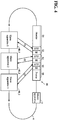
- Fig. 4 is a diagram illustrating a communication frame transmitted on the field network 4 according to this embodiment.
- a communication frame 50 is cyclically transmitted on the field network 4.
- the communication frame 50 sent out from the main processing apparatus 2, which is a master apparatus will be sequentially transferred to the remote apparatuses 40_1, 40_2 and 40_3 that are slave apparatuses.
- the communication frame 50 transferred to all the remote apparatuses 40 returns to the main processing apparatus 2.
- the communication frame 50 is cyclically transmitted to the main processing apparatus 2 and the remote apparatuses 40_1, 40_2, 40_3, ..., 40_N.
- the communication frame 50 includes a header 51, data areas 52, 53 and 54 assigned to the respective slave apparatuses, and a footer 55.
- the destination and various types of attribute information of the communication frame are stored in the header 51.
- OUT data and IN data for corresponding slave apparatuses are stored in the data areas 52, 53 and 54.
- Information such as an end code and parity bit is stored in the footer 55.
- the master apparatus generates the communication frame 50 by writing, in the data areas assigned to target slave apparatuses, OUT data to be given to the respective slave apparatuses, and sends out the communication frame 50 to the target slave apparatuses.
- each of the slave apparatuses Upon receiving the communication frame 50 from an upper side (upstream), each of the slave apparatuses extracts OUT data destined for that slave apparatus from the data area assigned to that slave apparatus, in the received communication frame 50, and writes, in the data area assigned to that slave apparatus, IN data collected by the slave apparatus so as to regenerate the communication frame 50, and sends out the communication frame 50 to a lower side (downstream).
- the communication frame 50 is cyclically transferred in this manner, and thereby OUT data and IN data are sequentially updated.
- the communication frame 50 in which OUT data (command values) destined for all the slave apparatuses is stored is sent out from the master apparatus, and the communication frame 50 after the OUT data (command values) and IN data (feedback values) are exchanged in each of the slave apparatuses returns to the master apparatus.
- data exchange between the master apparatus and each of the slave apparatuses is completed by the communication frame 50 making one round (circulation).
- FIGs. 5 are diagrams illustrating the overview of processing included in the PLC system 1 according to this embodiment.
- Fig. 5(a) is a diagram illustrating repeated execution of a program in a CPU unit according to a related technique
- Fig. 5(b) is a diagram illustrating repeated execution of a program in the CPU unit 10 according to this embodiment.
- a control-related program is repeatedly executed in cycles.
- the execution cycle of this program is also referred to as a "PLC system cycle" below.
- Programs that are executed include a system program 60 and a user program 70.
- the system program 60 is a program for executing processing required for an appropriate operation of the PLC system 1, and typically includes output processing 62, communication processing 64 and input processing 66.
- the output processing 62 includes processing for aggregating OUT data calculated by executing the user program 70 or the like and generating the communication frame 50 (also referred to as "framing processing", for example).
- the communication processing 64 includes processing for transmitting the generated communication frame 50 to slave apparatuses, and processing for collecting IN data from the communication frame 50 that has returned after circulating through all the slave apparatuses.
- the input processing 66 includes processing for updating internal data (or internal variables) that is based on the IN data collected from the returned communication frame 50.
- the user program 70 is a program generated as desired by the user of the PLC system 1 in accordance with a purpose and an application, and may be subdivided into one or a plurality of portions in accordance with contents to be controlled, a control target, control application or the like.
- the user program 70 can include a sequence control logic, a motion control logic, a PID control logic and the like.
- a priority order of an execution cycle or execution may be set in a user program subdivided into a plurality of portions.
- an execution cycle that is set for the user program is longer than a PLC system cycle (usually, an integral multiple of the PLC system cycle), and in this case, the program will be executed over a plurality of PLC system cycles.
- the user program 70 includes A processing 72, B processing 74 and C processing 76.
- the processor 100 which is a calculation unit, is configured to repeatedly execute the output processing 62 and the input processing 66 in a predetermined execution cycle (PLC system cycle), and to repeat program execution processing (execution processing of the user program 70) during a time period when the output processing 62 and the input processing 66 are not executed.
- the input processing 66 includes processing for updating input data in accordance with information (field information or IN data) that is collected from the control target by one or more slave apparatuses (the remote apparatuses 40).
- the output processing 62 includes processing for generating output data (communication frame or OUT data) that includes an execution result of the program execution processing (processing for executing the user program 70).
- the system program 60 is necessarily executed one time for each PLC system cycle. As shown in Fig. 5(a) , in the communication processing 64 of the system program 60, the communication frame 50 is sent out from the master apparatus, and unless the communication frame 50 circulates through all the slave apparatuses and returns to the master apparatus, update of OUT data and IN data between the master apparatus and the slave apparatuses cannot be completed.
- each of the slave apparatuses receives a command value (OUT data) from the communication frame 50, and adds a feedback value (IN data) to the communication frame 50.
- the master apparatus is in a waiting state until the communication frame 50 returns.
- the time required for the communication frame 50 sent out from the master apparatus to return to the master apparatus (hereinafter, also referred to as "one communication frame cycle D") is extended depending on the number of slave apparatuses connected to the field network 4.
- a PLC system cycle T2 corresponds to the total of the time required for executing the system program 60 (x1+x2+x3), and the time required for executing the user program 70 (x4+x5+x6).
- the user program 70 includes processing for which high-speed execution (repeated execution in a shorter cycle) like a motion control logic (continuous control logic of position (angle) of a multi-axis robot or the like) is requested, for example. Therefore, there is a demand that the PLC system cycle T2 is made as short as possible.
- the time required for the system program 60 to execute the communication processing 64 is relatively long as shown in Fig. 5(a) . This is because the system program 60 has to wait until the communication frame 50 that has been sent out returns.
- the present inventors focused on this waiting state in communication processing, and arrived at a new solution by shortening the PLC system cycle T2 by reducing the duration of this waiting state as much as possible or to zero. This new solution will be described with reference to Fig. 5(b) .
- the CPU unit 10 sends out, in one PLC system cycle, a communication frame 50A for mainly collecting IN data as well as a communication frame 50 that is similar to that in Fig. 5(a) .
- a communication frame 50A for mainly collecting IN data as well as a communication frame 50 that is similar to that in Fig. 5(a) .
- the time required for communication processing can be virtually ignored.
- the communication frame 50A for collecting IN data has returned to the master apparatus before the execution start of the input processing 66 that requires IN data collected from each slave apparatus, the input processing 66 can be immediately executed.
- the time required for communication processing can be made virtually zero, and a system program 65 that is executed will virtually include the output processing 62 and the input processing 66 only. Accordingly, before the communication frame 50 in the related technique shown in Fig. 5(a) is sent out from the master apparatus, the communication frame 50A for collecting IN data (feedback values) is sent out. Thereby, there is no waiting for the execution start of the input processing 66 and the communication frame 50 generated by the output processing 62 can be immediately sent out.
- the communication controller 110 starts cyclic transmission of the communication frame 50 (first data sequence) containing OUT data (output data or command values) for the one or more remote apparatuses 40 (slave apparatuses) in conjunction with execution of the output processing 62 in the processor 100 (calculation unit).
- the communication controller 110 starts, a predetermined time period before execution start of the input processing 66 in the processor 100 (calculation unit), cyclic transmission of the communication frame 50A (second data sequence) for obtaining information (field information or IN data) to be collected by the one or more remote apparatuses 40 (slave apparatuses) from the control target.
- a sending start timing of the communication frame 50A may be any timing, as long as the communication frame 50A that has been sent out collects IN data from all the slave apparatuses and returns to the master apparatus before start of the input processing 66 in a corresponding PLC system cycle.
- sending of the communication frame 50 should not be affected, and thus a timing when the communication frame 50A has been sent out and then returned to the master apparatus is preferably set to immediately before the start of the input processing 66.
- the communication frame 50 may be sent out from the master apparatus after the communication frame 50A is sent out from the master apparatus and before the communication frame 50A returns to the master apparatus.
- the communication frame 50A may be sent out from the master apparatus after the communication frame 50 is sent out from the master apparatus and before the communication frame 50 returns to the master apparatus. In other words, as long as the sending time periods of the communication frame 50 and the communication frame 50A do not overlap, sending start timings of those communication frames can be set as appropriate.
- one communication frame can be sent out after the other communication frame is sent out, independently from this communication frame circulating through the field network 4 and arriving at the master apparatus.
- a timing when one communication frame makes a circulation and then arrives at the master apparatus, and a sending timing of the other communication frame can be determined independently of each other.
- a timing of sending the communication frame 50A can be determined. Accordingly, it is sufficient that the communication frame 50A is sent out at a timing of the duration of the one communication frame cycle D2 before a start timing of the input processing 66.
- the execution timing of a control-related program (the system program 65 and the user program 70) is known, and thus the start timing of the input processing 66 can be known in advance. Therefore, in synchronization with the execution of the system program 65 and the user program 70, a sending timing of the communication frame 50A is determined in accordance with the length of the one communication frame cycle D2. Accordingly, the one communication frame cycle D2 corresponds to an offset value for determining a sending timing of the communication frame 50A.
- the one communication frame cycle D2 is actually measured in initialization processing executed when configuring the field network 4 using a master apparatus and one or more slave apparatuses. Accordingly, necessary information is exchanged between the master apparatus and the one or more slave apparatuses as initialization processing in order to establish a network between those apparatuses, and in this information exchange, the one communication frame cycle D2 is also actually measured.
- This measured length of the one communication frame cycle D2 is held in the CPU unit 10, and this value is used for determining a sending timing of the communication frame 50A as necessary. Accordingly, the length of the one communication frame cycle D2 is included in the initial configuration result of the network.
- the main processing apparatus 2 determines a timing for sending out the communication frame 50A (second data sequence) in this manner, based on an offset value stored in advance, using a timing of execution start of the input processing 66 as a reference.
- the main processing apparatus 2 determines the offset value based on the initial configuration result of the network.
- one communication frame cycle may be calculated in a predictive manner by simulation or the like. More specifically, it is possible to estimate the time required for the communication frame 50A circulating through the field network 4, based on the number of slave apparatuses that are connected to the field network 4, the type of each slave apparatus (the processing ability and data processing amount of each slave apparatus can be estimated) and the like. Without performing actual measurement, the one communication frame cycle D can be estimated in advance, and thus the designing of a program can be more simplified.
- the one communication frame cycle D2 is used as an offset value for determining a sending timing of the communication frame 50A.
- the main processing apparatus 2 master apparatus determines a timing for sending out the communication frame 50A (second data sequence) based on offset value stored in advance, using a timing of execution start of the input processing 66 as a reference.
- This offset value (the one communication frame cycle D2) may be determined by simulation, as described above.
- a timing for sending out the communication frame 50A may be determined as an absolute value of a time (count number) counted by the common timer (counter), or may be determined as a relative value using an execution start timing of the input processing 66 as a reference.
- the communication frames 50 and 50A, and processing in a slave apparatus will be described.
- the communication frame 50A can collect IN data. Therefore, as a data structure of the communication frame 50A, a structure dedicated to the collection of IN data may be adopted, or the same structure as that of the communication frame 50 may be adopted.
- Figs. 6 are diagrams showing an example of the data structure of a communication frame used in the PLC system 1 according to this embodiment.
- a structure shortened compared to the data structure of the communication frame 50 is adopted as the data structure of the communication frame 50A. More specifically, in the normal communication frame 50, data areas for OUT data and IN data assigned to respective slave apparatuses are provided between a header and a footer. An instruction that instructs each of the slave apparatuses to write, in the data area for IN data assigned to the slave apparatus, field information that is input in the slave apparatus (IN data refresh instruction) is stored in the header. Each slave apparatus writes the latest feedback value in the data area for IN data assigned to the slave apparatus, in accordance with the IN data refresh instruction in the header. At the same time, each slave apparatus reads out OUT data (command value) from the data area for OUT data assigned to the slave apparatus, and executes processing.
- OUT data command value
- the data areas for OUT data are deleted, and only the data areas for IN data exist.
- the IN data refresh instruction to each slave apparatus is stored in the header, and thus each slave apparatus writes the latest feedback value in the data area for IN data assigned to the slave apparatus in accordance with the IN data refresh instruction in the header.
- data areas for OUT data do not exist, and thus the frame length (data amount) of the communication frame 50A can be reduced. Accordingly, one communication frame cycle of the communication frame 50A can be shortened further, and a time margin for the communication frame 50 can be increased.
- the communication frame 50A shown in Fig. 6(b) has the same data structure as the communication frame 50.
- the communication frame 50 (first data sequence) and the communication frame 50A (second data sequence) have the same data structure.
- an invalid value is set as OUT data of the communication frame 50A.
- a "null value" is stored in each of the data areas for OUT data of the communication frame 50A, and the slave apparatuses cannot read out a valid OUT data when they receive the communication frame 50A. That is, the OUT data (output data) contained in the communication frame 50A (second data sequence) is invalidated.
- each data area for OUT data may also be invalidated by storing, in the data area, a value that cannot be OUT data (e.g., a negative value) instead of a "null value”.
- the communication frame 50 and the communication frame 50A have the same data structure, and thus both include an IN data refresh instruction.
- both the communication frame 50 (first data sequence) and the communication frame 50A (second data sequence) include a command for obtaining information from a slave apparatus (IN data refresh instruction) and OUT data (output data).
- Processing for generating a communication frame in the master apparatus can be commonalized by commonalizing the data structure of the communication frame 50 and the communication frame 50A in this manner, and it becomes possible to avoid the complication of an implementation mode in order to realize processing according to this embodiment.
- FIG. 6(c) an example is shown in which the communication frame 50A has the same data structure as the communication frame 50.
- the communication frame 50 (first data sequence) and the communication frame 50A (second data sequence) have the same data structure.
- a command value (OUT data) calculated by the most recent execution of a program required for controlling a control target is stored in the OUT data of the communication frame 50A as well, similarly to the communication frame 50.
- a declaration (declaration of invalidity of OUT data) indicating to each slave apparatus that the instruction values stored in the data areas for OUT data are invalid is stored in the header.
- each slave apparatus executes processing for discarding a received command value (OUT data). Accordingly, each of the slave apparatuses is configured to discard the output data included in the communication frame 50A (second data sequence).
- the OUT data (output data) included in the communication frame 50A (second data sequence) is virtually invalidated by using the declaration of invalidity of OUT data.
- any values stored in the data areas for OUT data are invalidated due to declaration of invalidity of OUT data, and thus random values may be stored in the data areas.
- the communication frame 50 and the communication frame 50A have the same data structure, and thus both include a command (IN data refresh instruction) for obtaining information from slave apparatuses and OUT data (output data).
- Processing for generating a communication frame in the master apparatus can be commonalized by commonalizing the data structure of the communication frame 50 and the communication frame 50A in this manner, and it becomes possible to avoid the complication of the implementation mode in order to realize processing according to this embodiment.
- Figs. 6(a) to 6(c) an example is shown in which the communication frame 50A whose data structure is different from that of the normal communication frame 50 is used, but perfectly the same communication frame as the communication frame 50 most recently sent out may be used as the communication frame 50A.
- the communication frame 50 sent out in the previous PLC system cycle may be sent out again in the current PLC system cycle.
- a pair of latest OUT data pieces is included in both the communication frames in common, and thus abnormal behavior of each slave apparatus does not occur.
- the communication frame 50A and the communication frame 50 do not necessarily need to have the same data structure. Furthermore, the data lengths of IN data and OUT data stored in each communication frame do not need to be the same. A minimum necessary data length may be dynamically selected in order to reduce the time required for transferring the communication frame. Alternatively, a configuration may be adopted in which optimum values for the data lengths of IN data and OUT data are estimated in advance from statistical information of communication frames on the network and the like, and the communication frame is determined so as to have the estimated data length.
- Figs. 7 are diagrams showing an implementation example of the CPU unit 10 according to this embodiment.
- the communication controller 110 includes an FPGA in which a control engine is implemented, and an ASIC in which a signal processing circuit such as analog/digital conversion or a memory is implemented.
- the FPGA in which the control engine is implemented generates internal signals, and thereby the communication frame 50A is generated and sent out.
- the processor 100 does not need to manage timings and the like, and high-speed control is enabled.
- a thread for managing timings may be executed such that the communication frame 50A is triggered from the thread.
- an internal command related to generation and sending of the communication frame 50A is given from the processor 100 to the communication controller 110.
- a processor 100_1 that executes a program (e.g., a user program or a system program) required for controlling a control target
- another processor 100_2 for executing a thread for managing timing is implemented.
- the processor 100_2 triggers the communication frame 50A.
- a dedicated processor 160 connected to the communication controller 110 is provided.
- the dedicated processor 160 manages timings, and gives an internal command for sending out the communication frame 50A to the communication controller 110, independently of the processor 100.
- a ring type network is illustrated, but the present invention can be applied to a daisy chain type network as well.
- a daisy chain type network will be explained with reference to Fig. 8 .
- Fig. 8 is a schematic diagram showing the entire configuration of a PLC system 1A according to a modified example of this embodiment.
- the PLC system 1A includes the main processing apparatus 2 (master apparatus), and one or more remote apparatuses 40 (slave apparatuses), and these are connected via a field network of a daisy chain type.
- communication frames are sequentially transferred from the master apparatus to the slave apparatuses (down frame), turn at an end portion, and are then sequentially transferred from the slave apparatuses to the master apparatus (up frame).
- the CPU unit 10 will have a communication controller 110A adapted to a daisy chain type.
- Other configurations, processing and the like are similar to those described above, and thus their detailed description is not repeated.
- processing for the master apparatus collecting field information from the one or more slave apparatuses via the network is executed in advance. Therefore, input processing that is executed after the collection of field information is complete is never waited for. Specifically, no waiting time occurs between processing for transmitting OUT data (command value) to each slave apparatus and processing for collecting IN data from each slave apparatus, and thus the cycle (PLC system cycle) for executing a program required for controlling a control target (including a user program and a system program) can be shortened. Accordingly, it is possible to provide an environment for executing a user program at a high speed. Accordingly, it is possible to execute a motion control logic and the like at a higher speed, and thus the control accuracy can be improved.
- Transmission buffer 122, 432 ... Transmission circuit, 130, 420 ... Reception buffer, 132, 422 ... Reception circuit, 160 ... Dedicated processor, 400 ... Calculation processing unit, 402 ... Input circuit, 404 ... Output circuit
Landscapes
- Engineering & Computer Science (AREA)
- Computer Networks & Wireless Communication (AREA)
- Signal Processing (AREA)
- Physics & Mathematics (AREA)
- General Physics & Mathematics (AREA)
- Automation & Control Theory (AREA)
- Programmable Controllers (AREA)
- Small-Scale Networks (AREA)
- Mobile Radio Communication Systems (AREA)
Claims (9)
- Système de commande (1) pour contrôler une cible de contrôle, comprenant :un appareil maître (2) incluant une unité de calcul (100) et une unité de traitement de communication (110) ; etun ou plusieurs appareils esclaves (40) connectés à l'appareil master (2) par un réseau (4), dans lequell'unité de traitement de communication (110) est configurée pour gérer une transmission cyclique, dans le réseau (4), d'une séquence de données (50) contenant des données maniées par l'appareil master (2) et le ou les appareils esclaves (40),l'unité de calcul (100) est configurée pour exécuter un traitement de sortie (62) et un traitement d'entrée (66) de façon répétitive dans un cycle d'exécution prédéterminé, et pour répéter un traitement d'exécution de programme pendant une période de temps durant laquelle le traitement de sortie (62) et le traitement d'entrée (66) ne sont pas exécutés, le traitement d'entrée (66) incluant un traitement pour actualiser des données d'entrée en accord avec une information collectée de la cible de contrôle par le ou les appareils esclaves (40), et le traitement de sortie (62) incluant un traitement pour générer des données de sortie qui incluent un résultat d'exécution du traitement d'exécution de programme, etl'unité de traitement de communication (110) est configuré pour :commencer une transmission cyclique d'une première séquence de données (50) contenant les données de sortie du ou des appareils esclaves (40) conjointement avec le traitement de sortie (62) par l'unité de calcul (100) ; etcommencer, une durée de temps prédéterminée avant un début d'exécution du traitement d'entrée (66) par l'unité de calcul (100), une transmission cyclique d'une deuxième séquence de données (50A) afin d'obtenir une information collectée par le ou les appareils esclaves (40) de la cible de contrôle ; dans lequella première séquence de données (50) et la deuxième séquence de données (50A) incluent une commande pour obtenir une information du ou des appareils esclaves (40) et les données de sortie.
- Système de commande selon la revendication 1, dans lequel
après que la première séquence de données (50) soit envoyée, l'unité de traitement de communication (110) envoi la deuxième séquence de données (50A) indépendamment de l'arrivée de la première séquence de données (50) à l'appareil master (2). - Système de commande selon la revendication 1 ou 2, dans lequel
la première séquence de données (50) et la deuxième séquence de données (50A) ont la même structure de données. - Système de commande selon l'une des revendications 1 à 3, dans lequel
les données de sortie contenues dans la deuxième séquence de données (50A) sont invalidées. - Système de commande selon l'une des revendications 1 à 3, dans lequel
chacun du ou des appareils esclaves (40) est configuré pour rejeter les données de sortie contenues dans la deuxième séquence de données (50A). - Système de commande selon l'une des revendications 1 à 4, dans lequel
l'appareil master (2) détermine un moment pour envoyer la deuxième séquence de données (50A) basé sur une valeur de marge stockée en avance, en utilisant un moment de commencement d'exécution du traitement d'entrée (66) comme référence. - Système de commande selon la revendication 6, dans lequel
l'appareil master (2) détermine la valeur de marge basé sur un résultat de configuration initiale du réseau (4). - Appareil de contrôle (2) pour contrôler une cible de contrôle, comprenant :une unité de calcul (100); etune unité de traitement de communication (110) connectée à l'unité de calcul (100), dans lequell'appareil de contrôle (2) est connecté à un ou plusieurs appareils esclaves (40) par un réseau,l'unité de traitement de communication (110) est configuré pour gérer une transmission cyclique, dans le réseau (4), d'une séquence de données (50) contenant des données maniées par l'appareil master (2) et le ou les appareils esclaves (40),l'unité de calcul (100) est configurée pour exécuter un traitement de sortie (62) et un traitement d'entrée (66) de façon répétitive dans un cycle d'exécution prédéterminé, et pour répéter un traitement d'exécution de programme pendant une période de temps durant laquelle le traitement de sortie (62) et le traitement d'entrée (66) ne sont pas exécutés, le traitement d'entrée (66) incluant un traitement pour actualiser des données d'entrée en accord avec une information collectée de la cible de contrôle par le ou les appareils esclaves (40), et le traitement de sortie (62) incluant un traitement pour générer des données de sortie qui incluent un résultat d'exécution du traitement d'exécution de programme, etl'unité de traitement de communication (110) est configuré pour :commencer une transmission cyclique d'une première séquence de données (50) contenant les données de sortie du ou des appareils esclaves (40) conjointement avec le traitement de sortie (62) par l'unité de calcul (100) ; etcommencer, une durée de temps prédéterminée avant un début d'exécution du traitement d'entrée (66) par l'unité de calcul (100), une transmission cyclique d'une deuxième séquence de données (50A) afin d'obtenir une information collectée par le ou les appareils esclaves (40) de la cible de contrôle ; dans lequella première séquence de données (50) et la deuxième séquence de données (50A) incluent une commande pour obtenir une information du ou des appareils esclaves (40) et les données de sortie.
- Procédé de contrôle dans un appareil de contrôle (2) pour contrôler une cible de contrôle, dans lequel
l'appareil de contrôle est connecté à un ou plusieurs appareils esclaves (40) par un réseau (4), et est configuré pour gérer une transmission cyclique, dans le réseau (4), d'une séquence de données (50) contenant des données maniées par l'appareil master (2) et le ou les appareils esclaves (40),
le procédé comprenant les étapes suivantes :exécution d'un traitement de sortie (62) et un traitement d'entrée (66) de façon répétitive dans un cycle d'exécution prédéterminé, et répétition d'un traitement d'exécution de programme pendant une période de temps durant laquelle le traitement de sortie (62) et le traitement d'entrée (66) ne sont pas exécutés, le traitement d'entrée (66) incluant un traitement pour actualiser des données d'entrée en accord avec une information collectée de la cible de contrôle par le ou les appareils esclaves (40), et le traitement de sortie (62) incluant un traitement pour générer des données de sortie qui incluent un résultat d'exécution du traitement d'exécution de programme;commencement d'une transmission cyclique d'une première séquence de données (50) contenant les données de sortie du ou des appareils esclaves (40) conjointement avec le traitement de sortie (62) ; etcommencement, une durée de temps prédéterminée avant un début d'exécution du traitement d'entrée (66), d'une transmission cyclique d'une deuxième séquence de données (50A) afin d'obtenir une information collectée par le ou les appareils esclaves (40) de la cible de contrôle ; dans lequella première séquence de données (50) et la deuxième séquence de données (50A) incluent une commande pour obtenir une information du ou des appareils esclaves (40) et les données de sortie.
Applications Claiming Priority (2)
| Application Number | Priority Date | Filing Date | Title |
|---|---|---|---|
| JP2014041535 | 2014-03-04 | ||
| PCT/JP2015/050921 WO2015133175A1 (fr) | 2014-03-04 | 2015-01-15 | Système de commande, dispositif de commande, et procédé de commande |
Publications (3)
| Publication Number | Publication Date |
|---|---|
| EP3116166A1 EP3116166A1 (fr) | 2017-01-11 |
| EP3116166A4 EP3116166A4 (fr) | 2017-08-30 |
| EP3116166B1 true EP3116166B1 (fr) | 2018-09-05 |
Family
ID=54054987
Family Applications (1)
| Application Number | Title | Priority Date | Filing Date |
|---|---|---|---|
| EP15758998.7A Active EP3116166B1 (fr) | 2014-03-04 | 2015-01-15 | Système de commande, dispositif de commande, et procédé de commande |
Country Status (5)
| Country | Link |
|---|---|
| US (1) | US10277417B2 (fr) |
| EP (1) | EP3116166B1 (fr) |
| JP (1) | JP6187674B2 (fr) |
| CN (1) | CN106063197B (fr) |
| WO (1) | WO2015133175A1 (fr) |
Families Citing this family (28)
| Publication number | Priority date | Publication date | Assignee | Title |
|---|---|---|---|---|
| KR102023534B1 (ko) * | 2015-04-17 | 2019-09-23 | 엘에스산전 주식회사 | 슬레이브 디바이스 및 이의 제어 방법 |
| WO2017046916A1 (fr) * | 2015-09-17 | 2017-03-23 | 株式会社安川電機 | Système de communication de dispositif industriel, procédé de communication et dispositif industriel |
| KR102416176B1 (ko) | 2016-05-10 | 2022-07-01 | 엘에스일렉트릭(주) | 슬레이브 디바이스 제어 방법 |
| JP6812726B2 (ja) * | 2016-09-30 | 2021-01-13 | オムロン株式会社 | 制御ユニット、データリフレッシュ方法、データリフレッシュプログラム |
| JP6812727B2 (ja) * | 2016-09-30 | 2021-01-13 | オムロン株式会社 | 安全制御ユニット、安全制御方法、安全制御プログラム |
| US10311009B2 (en) * | 2016-10-24 | 2019-06-04 | Fisher-Rosemount Systems, Inc. | Apparatus and methods for communicatively coupling field devices to controllers in a process control system using a distributed marshaling architecture |
| JP6376229B2 (ja) * | 2017-02-09 | 2018-08-22 | オムロン株式会社 | 通信システム、通信装置および通信方法 |
| US10089276B1 (en) | 2017-03-17 | 2018-10-02 | Eaton Intelligent Power Limited | Distributed logic control apparatus |
| US10268173B2 (en) | 2017-03-17 | 2019-04-23 | Eaton Intelligent Power Limited | Distributed logic control apparatus |
| JP6724847B2 (ja) * | 2017-03-31 | 2020-07-15 | オムロン株式会社 | 制御装置、制御プログラム、制御システム、および制御方法 |
| US10624707B2 (en) * | 2017-09-18 | 2020-04-21 | Verb Surgical Inc. | Robotic surgical system and method for communicating synchronous and asynchronous information to and from nodes of a robotic arm |
| US10779901B2 (en) | 2017-09-18 | 2020-09-22 | Verb Surgical Inc. | Robotic surgical system having a communication network of a ring topology and method for use therewith |
| DE102017121886A1 (de) * | 2017-09-21 | 2019-03-21 | Destaco Europe Gmbh | Anlage für den Karosseriebau |
| JP7031204B2 (ja) * | 2017-09-29 | 2022-03-08 | オムロン株式会社 | 制御装置、制御装置の制御方法、情報処理プログラム、および記録媒体 |
| JP7020198B2 (ja) * | 2018-03-09 | 2022-02-16 | オムロン株式会社 | 制御装置および制御システム |
| JP7231073B2 (ja) * | 2018-03-09 | 2023-03-01 | オムロン株式会社 | 制御装置および制御システム |
| JP6939665B2 (ja) * | 2018-03-15 | 2021-09-22 | オムロン株式会社 | ネットワークシステム |
| JP7189499B2 (ja) | 2018-05-07 | 2022-12-14 | オムロン株式会社 | センサシステム |
| JP7068654B2 (ja) * | 2018-06-07 | 2022-05-17 | オムロン株式会社 | センサシステム |
| JP7143697B2 (ja) * | 2018-09-14 | 2022-09-29 | オムロン株式会社 | 制御システムおよび制御装置 |
| US11531381B2 (en) | 2018-09-28 | 2022-12-20 | Fisher-Rosemount Systems, Inc. | Smart functionality for discrete field devices and signals |
| KR20210111253A (ko) * | 2019-01-07 | 2021-09-10 | 스미도모쥬기가이고교 가부시키가이샤 | 모션컨트롤러 및 성형기 |
| JP7216357B2 (ja) * | 2019-03-01 | 2023-02-01 | 日本電気株式会社 | 制御装置、制御システム、ネットワークシステム、制御方法、制御プログラムおよび光ネットワークシステム |
| JP7275940B2 (ja) * | 2019-07-08 | 2023-05-18 | オムロン株式会社 | 制御プログラムおよび方法 |
| JP2022083142A (ja) * | 2020-11-24 | 2022-06-03 | オムロン株式会社 | 制御装置、通信制御方法、および制御プログラム |
| JP2022155141A (ja) * | 2021-03-30 | 2022-10-13 | キヤノン株式会社 | 制御装置、システム、基板処理装置、物品の製造方法、制御方法及びプログラム |
| WO2024009633A1 (fr) * | 2022-07-05 | 2024-01-11 | パナソニックIpマネジメント株式会社 | Dispositif de commande, procédé de commande et programme |
| JP7374379B1 (ja) * | 2022-10-14 | 2023-11-06 | 三菱電機株式会社 | データ収集装置、データ収集システム、データベース作成方法及びプログラム |
Family Cites Families (11)
| Publication number | Priority date | Publication date | Assignee | Title |
|---|---|---|---|---|
| JPH073979B2 (ja) * | 1987-09-14 | 1995-01-18 | 三菱電機株式会社 | 遠方監視制御システム |
| JP2001147905A (ja) | 1999-11-24 | 2001-05-29 | Fuji Electric Co Ltd | プログラマブルコントローラシステム |
| JP4793585B2 (ja) * | 2006-03-15 | 2011-10-12 | オムロン株式会社 | プログラマブル・コントローラ |
| DE102007004044B4 (de) * | 2007-01-22 | 2009-09-10 | Phoenix Contact Gmbh & Co. Kg | Verfahren und Anlage zur optimierten Übertragung von Daten zwischen einer Steuereinrichtung und mehreren Feldgeräten |
| DE102009045384A1 (de) * | 2009-10-06 | 2011-04-07 | Endress + Hauser Process Solutions Ag | Verfahren zum Betreiben eines Feldbus-Interface |
| EP2407840A1 (fr) * | 2010-07-16 | 2012-01-18 | Siemens Aktiengesellschaft | Procédé pour faire fonctionner un dispositif d'automatisation |
| JP4894961B1 (ja) | 2011-03-15 | 2012-03-14 | オムロン株式会社 | Plcのcpuユニット、plc用システムプログラムおよびplc用システムプログラムを格納した記録媒体 |
| JP2013081065A (ja) * | 2011-10-04 | 2013-05-02 | Sumitomo Electric Ind Ltd | 省電力制御方法、局側装置および通信システム |
| WO2013137023A1 (fr) | 2012-03-15 | 2013-09-19 | オムロン株式会社 | Dispositif de commande, dispositif de traitement d'image, procédé de commande, support d'enregistrement lisible par ordinateur, et programme |
| JP6167532B2 (ja) | 2013-01-25 | 2017-07-26 | オムロン株式会社 | 制御装置および制御装置の動作方法 |
| US9915939B2 (en) * | 2013-12-13 | 2018-03-13 | General Electric Company | Systems and methods for providing multiple frame rates on a common physical network |
-
2015
- 2015-01-15 US US15/122,517 patent/US10277417B2/en active Active
- 2015-01-15 EP EP15758998.7A patent/EP3116166B1/fr active Active
- 2015-01-15 WO PCT/JP2015/050921 patent/WO2015133175A1/fr active Application Filing
- 2015-01-15 JP JP2016506162A patent/JP6187674B2/ja active Active
- 2015-01-15 CN CN201580011512.0A patent/CN106063197B/zh active Active
Non-Patent Citations (1)
| Title |
|---|
| None * |
Also Published As
| Publication number | Publication date |
|---|---|
| US10277417B2 (en) | 2019-04-30 |
| EP3116166A1 (fr) | 2017-01-11 |
| JPWO2015133175A1 (ja) | 2017-04-06 |
| US20170099158A1 (en) | 2017-04-06 |
| EP3116166A4 (fr) | 2017-08-30 |
| CN106063197A (zh) | 2016-10-26 |
| CN106063197B (zh) | 2019-04-09 |
| WO2015133175A1 (fr) | 2015-09-11 |
| JP6187674B2 (ja) | 2017-08-30 |
Similar Documents
| Publication | Publication Date | Title |
|---|---|---|
| EP3116166B1 (fr) | Système de commande, dispositif de commande, et procédé de commande | |
| CN111034128B (zh) | 控制系统以及控制装置 | |
| US10356006B2 (en) | Control system, development support apparatus, controller, and control method | |
| KR20120099222A (ko) | Plc와 그의 작동방법 및 plc 시스템 | |
| EP4050436A1 (fr) | Dispositif de commande et système de commande distribuée | |
| JP7003951B2 (ja) | 制御システム | |
| JP7396393B2 (ja) | 制御システム、装置および制御方法 | |
| US11269313B2 (en) | Controller and control system that stores data in current control cycle for output in next control cycle | |
| JP6939665B2 (ja) | ネットワークシステム | |
| US11068423B2 (en) | Control device and communication device | |
| JP7231073B2 (ja) | 制御装置および制御システム | |
| Puiu et al. | The synchronous control of nodes and the message time delays estimation for a CAN network | |
| Hallmans et al. | Consistent sensor values on a real-time ethernet network | |
| JP2009077111A (ja) | Ieee1394応用マスタ・スレーブ同期通信システムおよびその方法 |
Legal Events
| Date | Code | Title | Description |
|---|---|---|---|
| PUAI | Public reference made under article 153(3) epc to a published international application that has entered the european phase |
Free format text: ORIGINAL CODE: 0009012 |
|
| STAA | Information on the status of an ep patent application or granted ep patent |
Free format text: STATUS: REQUEST FOR EXAMINATION WAS MADE |
|
| 17P | Request for examination filed |
Effective date: 20160826 |
|
| AK | Designated contracting states |
Kind code of ref document: A1 Designated state(s): AL AT BE BG CH CY CZ DE DK EE ES FI FR GB GR HR HU IE IS IT LI LT LU LV MC MK MT NL NO PL PT RO RS SE SI SK SM TR |
|
| AX | Request for extension of the european patent |
Extension state: BA ME |
|
| DAX | Request for extension of the european patent (deleted) | ||
| A4 | Supplementary search report drawn up and despatched |
Effective date: 20170802 |
|
| RIC1 | Information provided on ipc code assigned before grant |
Ipc: G05B 19/05 20060101ALI20170727BHEP Ipc: H04L 12/423 20060101ALI20170727BHEP Ipc: H04L 12/40 20060101ALI20170727BHEP Ipc: H04L 12/42 20060101ALI20170727BHEP Ipc: H04L 12/28 20060101AFI20170727BHEP Ipc: H04L 12/403 20060101ALI20170727BHEP |
|
| GRAP | Despatch of communication of intention to grant a patent |
Free format text: ORIGINAL CODE: EPIDOSNIGR1 |
|
| STAA | Information on the status of an ep patent application or granted ep patent |
Free format text: STATUS: GRANT OF PATENT IS INTENDED |
|
| INTG | Intention to grant announced |
Effective date: 20180323 |
|
| GRAS | Grant fee paid |
Free format text: ORIGINAL CODE: EPIDOSNIGR3 |
|
| GRAA | (expected) grant |
Free format text: ORIGINAL CODE: 0009210 |
|
| STAA | Information on the status of an ep patent application or granted ep patent |
Free format text: STATUS: THE PATENT HAS BEEN GRANTED |
|
| AK | Designated contracting states |
Kind code of ref document: B1 Designated state(s): AL AT BE BG CH CY CZ DE DK EE ES FI FR GB GR HR HU IE IS IT LI LT LU LV MC MK MT NL NO PL PT RO RS SE SI SK SM TR |
|
| REG | Reference to a national code |
Ref country code: GB Ref legal event code: FG4D |
|
| REG | Reference to a national code |
Ref country code: CH Ref legal event code: EP |
|
| REG | Reference to a national code |
Ref country code: AT Ref legal event code: REF Ref document number: 1039176 Country of ref document: AT Kind code of ref document: T Effective date: 20180915 |
|
| REG | Reference to a national code |
Ref country code: IE Ref legal event code: FG4D |
|
| REG | Reference to a national code |
Ref country code: DE Ref legal event code: R096 Ref document number: 602015015807 Country of ref document: DE |
|
| REG | Reference to a national code |
Ref country code: NL Ref legal event code: MP Effective date: 20180905 |
|
| REG | Reference to a national code |
Ref country code: LT Ref legal event code: MG4D |
|
| PG25 | Lapsed in a contracting state [announced via postgrant information from national office to epo] |
Ref country code: GR Free format text: LAPSE BECAUSE OF FAILURE TO SUBMIT A TRANSLATION OF THE DESCRIPTION OR TO PAY THE FEE WITHIN THE PRESCRIBED TIME-LIMIT Effective date: 20181206 Ref country code: SE Free format text: LAPSE BECAUSE OF FAILURE TO SUBMIT A TRANSLATION OF THE DESCRIPTION OR TO PAY THE FEE WITHIN THE PRESCRIBED TIME-LIMIT Effective date: 20180905 Ref country code: BG Free format text: LAPSE BECAUSE OF FAILURE TO SUBMIT A TRANSLATION OF THE DESCRIPTION OR TO PAY THE FEE WITHIN THE PRESCRIBED TIME-LIMIT Effective date: 20181205 Ref country code: NO Free format text: LAPSE BECAUSE OF FAILURE TO SUBMIT A TRANSLATION OF THE DESCRIPTION OR TO PAY THE FEE WITHIN THE PRESCRIBED TIME-LIMIT Effective date: 20181205 Ref country code: RS Free format text: LAPSE BECAUSE OF FAILURE TO SUBMIT A TRANSLATION OF THE DESCRIPTION OR TO PAY THE FEE WITHIN THE PRESCRIBED TIME-LIMIT Effective date: 20180905 Ref country code: FI Free format text: LAPSE BECAUSE OF FAILURE TO SUBMIT A TRANSLATION OF THE DESCRIPTION OR TO PAY THE FEE WITHIN THE PRESCRIBED TIME-LIMIT Effective date: 20180905 Ref country code: LT Free format text: LAPSE BECAUSE OF FAILURE TO SUBMIT A TRANSLATION OF THE DESCRIPTION OR TO PAY THE FEE WITHIN THE PRESCRIBED TIME-LIMIT Effective date: 20180905 |
|
| REG | Reference to a national code |
Ref country code: AT Ref legal event code: MK05 Ref document number: 1039176 Country of ref document: AT Kind code of ref document: T Effective date: 20180905 |
|
| PG25 | Lapsed in a contracting state [announced via postgrant information from national office to epo] |
Ref country code: AL Free format text: LAPSE BECAUSE OF FAILURE TO SUBMIT A TRANSLATION OF THE DESCRIPTION OR TO PAY THE FEE WITHIN THE PRESCRIBED TIME-LIMIT Effective date: 20180905 Ref country code: LV Free format text: LAPSE BECAUSE OF FAILURE TO SUBMIT A TRANSLATION OF THE DESCRIPTION OR TO PAY THE FEE WITHIN THE PRESCRIBED TIME-LIMIT Effective date: 20180905 Ref country code: HR Free format text: LAPSE BECAUSE OF FAILURE TO SUBMIT A TRANSLATION OF THE DESCRIPTION OR TO PAY THE FEE WITHIN THE PRESCRIBED TIME-LIMIT Effective date: 20180905 |
|
| PG25 | Lapsed in a contracting state [announced via postgrant information from national office to epo] |
Ref country code: EE Free format text: LAPSE BECAUSE OF FAILURE TO SUBMIT A TRANSLATION OF THE DESCRIPTION OR TO PAY THE FEE WITHIN THE PRESCRIBED TIME-LIMIT Effective date: 20180905 Ref country code: PL Free format text: LAPSE BECAUSE OF FAILURE TO SUBMIT A TRANSLATION OF THE DESCRIPTION OR TO PAY THE FEE WITHIN THE PRESCRIBED TIME-LIMIT Effective date: 20180905 Ref country code: IS Free format text: LAPSE BECAUSE OF FAILURE TO SUBMIT A TRANSLATION OF THE DESCRIPTION OR TO PAY THE FEE WITHIN THE PRESCRIBED TIME-LIMIT Effective date: 20190105 Ref country code: ES Free format text: LAPSE BECAUSE OF FAILURE TO SUBMIT A TRANSLATION OF THE DESCRIPTION OR TO PAY THE FEE WITHIN THE PRESCRIBED TIME-LIMIT Effective date: 20180905 Ref country code: NL Free format text: LAPSE BECAUSE OF FAILURE TO SUBMIT A TRANSLATION OF THE DESCRIPTION OR TO PAY THE FEE WITHIN THE PRESCRIBED TIME-LIMIT Effective date: 20180905 Ref country code: RO Free format text: LAPSE BECAUSE OF FAILURE TO SUBMIT A TRANSLATION OF THE DESCRIPTION OR TO PAY THE FEE WITHIN THE PRESCRIBED TIME-LIMIT Effective date: 20180905 Ref country code: IT Free format text: LAPSE BECAUSE OF FAILURE TO SUBMIT A TRANSLATION OF THE DESCRIPTION OR TO PAY THE FEE WITHIN THE PRESCRIBED TIME-LIMIT Effective date: 20180905 Ref country code: CZ Free format text: LAPSE BECAUSE OF FAILURE TO SUBMIT A TRANSLATION OF THE DESCRIPTION OR TO PAY THE FEE WITHIN THE PRESCRIBED TIME-LIMIT Effective date: 20180905 Ref country code: AT Free format text: LAPSE BECAUSE OF FAILURE TO SUBMIT A TRANSLATION OF THE DESCRIPTION OR TO PAY THE FEE WITHIN THE PRESCRIBED TIME-LIMIT Effective date: 20180905 |
|
| PG25 | Lapsed in a contracting state [announced via postgrant information from national office to epo] |
Ref country code: SM Free format text: LAPSE BECAUSE OF FAILURE TO SUBMIT A TRANSLATION OF THE DESCRIPTION OR TO PAY THE FEE WITHIN THE PRESCRIBED TIME-LIMIT Effective date: 20180905 Ref country code: PT Free format text: LAPSE BECAUSE OF FAILURE TO SUBMIT A TRANSLATION OF THE DESCRIPTION OR TO PAY THE FEE WITHIN THE PRESCRIBED TIME-LIMIT Effective date: 20190105 Ref country code: SK Free format text: LAPSE BECAUSE OF FAILURE TO SUBMIT A TRANSLATION OF THE DESCRIPTION OR TO PAY THE FEE WITHIN THE PRESCRIBED TIME-LIMIT Effective date: 20180905 |
|
| REG | Reference to a national code |
Ref country code: DE Ref legal event code: R097 Ref document number: 602015015807 Country of ref document: DE |
|
| PLBE | No opposition filed within time limit |
Free format text: ORIGINAL CODE: 0009261 |
|
| STAA | Information on the status of an ep patent application or granted ep patent |
Free format text: STATUS: NO OPPOSITION FILED WITHIN TIME LIMIT |
|
| PG25 | Lapsed in a contracting state [announced via postgrant information from national office to epo] |
Ref country code: DK Free format text: LAPSE BECAUSE OF FAILURE TO SUBMIT A TRANSLATION OF THE DESCRIPTION OR TO PAY THE FEE WITHIN THE PRESCRIBED TIME-LIMIT Effective date: 20180905 |
|
| 26N | No opposition filed |
Effective date: 20190606 |
|
| PG25 | Lapsed in a contracting state [announced via postgrant information from national office to epo] |
Ref country code: MC Free format text: LAPSE BECAUSE OF FAILURE TO SUBMIT A TRANSLATION OF THE DESCRIPTION OR TO PAY THE FEE WITHIN THE PRESCRIBED TIME-LIMIT Effective date: 20180905 Ref country code: SI Free format text: LAPSE BECAUSE OF FAILURE TO SUBMIT A TRANSLATION OF THE DESCRIPTION OR TO PAY THE FEE WITHIN THE PRESCRIBED TIME-LIMIT Effective date: 20180905 |
|
| REG | Reference to a national code |
Ref country code: CH Ref legal event code: PL |
|
| GBPC | Gb: european patent ceased through non-payment of renewal fee |
Effective date: 20190115 |
|
| PG25 | Lapsed in a contracting state [announced via postgrant information from national office to epo] |
Ref country code: LU Free format text: LAPSE BECAUSE OF NON-PAYMENT OF DUE FEES Effective date: 20190115 |
|
| REG | Reference to a national code |
Ref country code: BE Ref legal event code: MM Effective date: 20190131 |
|
| REG | Reference to a national code |
Ref country code: IE Ref legal event code: MM4A |
|
| PG25 | Lapsed in a contracting state [announced via postgrant information from national office to epo] |
Ref country code: FR Free format text: LAPSE BECAUSE OF NON-PAYMENT OF DUE FEES Effective date: 20190131 |
|
| PG25 | Lapsed in a contracting state [announced via postgrant information from national office to epo] |
Ref country code: BE Free format text: LAPSE BECAUSE OF NON-PAYMENT OF DUE FEES Effective date: 20190131 |
|
| PG25 | Lapsed in a contracting state [announced via postgrant information from national office to epo] |
Ref country code: CH Free format text: LAPSE BECAUSE OF NON-PAYMENT OF DUE FEES Effective date: 20190131 Ref country code: LI Free format text: LAPSE BECAUSE OF NON-PAYMENT OF DUE FEES Effective date: 20190131 Ref country code: GB Free format text: LAPSE BECAUSE OF NON-PAYMENT OF DUE FEES Effective date: 20190115 |
|
| PG25 | Lapsed in a contracting state [announced via postgrant information from national office to epo] |
Ref country code: IE Free format text: LAPSE BECAUSE OF NON-PAYMENT OF DUE FEES Effective date: 20190115 |
|
| PG25 | Lapsed in a contracting state [announced via postgrant information from national office to epo] |
Ref country code: TR Free format text: LAPSE BECAUSE OF FAILURE TO SUBMIT A TRANSLATION OF THE DESCRIPTION OR TO PAY THE FEE WITHIN THE PRESCRIBED TIME-LIMIT Effective date: 20180905 |
|
| PG25 | Lapsed in a contracting state [announced via postgrant information from national office to epo] |
Ref country code: MT Free format text: LAPSE BECAUSE OF NON-PAYMENT OF DUE FEES Effective date: 20190115 |
|
| PG25 | Lapsed in a contracting state [announced via postgrant information from national office to epo] |
Ref country code: CY Free format text: LAPSE BECAUSE OF FAILURE TO SUBMIT A TRANSLATION OF THE DESCRIPTION OR TO PAY THE FEE WITHIN THE PRESCRIBED TIME-LIMIT Effective date: 20180905 |
|
| PG25 | Lapsed in a contracting state [announced via postgrant information from national office to epo] |
Ref country code: HU Free format text: LAPSE BECAUSE OF FAILURE TO SUBMIT A TRANSLATION OF THE DESCRIPTION OR TO PAY THE FEE WITHIN THE PRESCRIBED TIME-LIMIT; INVALID AB INITIO Effective date: 20150115 |
|
| PG25 | Lapsed in a contracting state [announced via postgrant information from national office to epo] |
Ref country code: MK Free format text: LAPSE BECAUSE OF FAILURE TO SUBMIT A TRANSLATION OF THE DESCRIPTION OR TO PAY THE FEE WITHIN THE PRESCRIBED TIME-LIMIT Effective date: 20180905 |
|
| PGFP | Annual fee paid to national office [announced via postgrant information from national office to epo] |
Ref country code: DE Payment date: 20221130 Year of fee payment: 9 |