EP3116101A1 - Armature core, armature, and electric motor - Google Patents
Armature core, armature, and electric motor Download PDFInfo
- Publication number
- EP3116101A1 EP3116101A1 EP15758671.0A EP15758671A EP3116101A1 EP 3116101 A1 EP3116101 A1 EP 3116101A1 EP 15758671 A EP15758671 A EP 15758671A EP 3116101 A1 EP3116101 A1 EP 3116101A1
- Authority
- EP
- European Patent Office
- Prior art keywords
- winding
- armature
- coil
- wound
- layer coil
- Prior art date
- Legal status (The legal status is an assumption and is not a legal conclusion. Google has not performed a legal analysis and makes no representation as to the accuracy of the status listed.)
- Granted
Links
- 238000004804 winding Methods 0.000 claims abstract description 226
- 230000001105 regulatory effect Effects 0.000 claims abstract description 47
- 230000001846 repelling effect Effects 0.000 claims description 5
- 230000004048 modification Effects 0.000 description 20
- 238000012986 modification Methods 0.000 description 20
- 239000003638 chemical reducing agent Substances 0.000 description 8
- 238000000034 method Methods 0.000 description 6
- 230000002093 peripheral effect Effects 0.000 description 4
- 230000000694 effects Effects 0.000 description 3
- 239000000463 material Substances 0.000 description 3
- 230000002265 prevention Effects 0.000 description 2
- 239000004020 conductor Substances 0.000 description 1
- 210000003298 dental enamel Anatomy 0.000 description 1
- 239000000428 dust Substances 0.000 description 1
- 239000003822 epoxy resin Substances 0.000 description 1
- 239000012212 insulator Substances 0.000 description 1
- 239000000696 magnetic material Substances 0.000 description 1
- 239000006247 magnetic powder Substances 0.000 description 1
- 239000002184 metal Substances 0.000 description 1
- 238000000465 moulding Methods 0.000 description 1
- 229920000647 polyepoxide Polymers 0.000 description 1
- 239000000843 powder Substances 0.000 description 1
- 229920005989 resin Polymers 0.000 description 1
- 239000011347 resin Substances 0.000 description 1
- 238000000926 separation method Methods 0.000 description 1
- 238000003466 welding Methods 0.000 description 1
Images




Classifications
-
- H—ELECTRICITY
- H02—GENERATION; CONVERSION OR DISTRIBUTION OF ELECTRIC POWER
- H02K—DYNAMO-ELECTRIC MACHINES
- H02K3/00—Details of windings
- H02K3/46—Fastening of windings on the stator or rotor structure
- H02K3/52—Fastening salient pole windings or connections thereto
- H02K3/527—Fastening salient pole windings or connections thereto applicable to rotors only
-
- H—ELECTRICITY
- H02—GENERATION; CONVERSION OR DISTRIBUTION OF ELECTRIC POWER
- H02K—DYNAMO-ELECTRIC MACHINES
- H02K1/00—Details of the magnetic circuit
- H02K1/06—Details of the magnetic circuit characterised by the shape, form or construction
- H02K1/12—Stationary parts of the magnetic circuit
- H02K1/17—Stator cores with permanent magnets
-
- H—ELECTRICITY
- H02—GENERATION; CONVERSION OR DISTRIBUTION OF ELECTRIC POWER
- H02K—DYNAMO-ELECTRIC MACHINES
- H02K1/00—Details of the magnetic circuit
- H02K1/06—Details of the magnetic circuit characterised by the shape, form or construction
- H02K1/22—Rotating parts of the magnetic circuit
- H02K1/26—Rotor cores with slots for windings
- H02K1/265—Shape, form or location of the slots
-
- H—ELECTRICITY
- H02—GENERATION; CONVERSION OR DISTRIBUTION OF ELECTRIC POWER
- H02K—DYNAMO-ELECTRIC MACHINES
- H02K23/00—DC commutator motors or generators having mechanical commutator; Universal AC/DC commutator motors
- H02K23/26—DC commutator motors or generators having mechanical commutator; Universal AC/DC commutator motors characterised by the armature windings
- H02K23/38—DC commutator motors or generators having mechanical commutator; Universal AC/DC commutator motors characterised by the armature windings having winding or connection for improving commutation, e.g. equipotential connection
-
- H—ELECTRICITY
- H02—GENERATION; CONVERSION OR DISTRIBUTION OF ELECTRIC POWER
- H02K—DYNAMO-ELECTRIC MACHINES
- H02K23/00—DC commutator motors or generators having mechanical commutator; Universal AC/DC commutator motors
- H02K23/40—DC commutator motors or generators having mechanical commutator; Universal AC/DC commutator motors characterised by the arrangement of the magnet circuits
-
- H—ELECTRICITY
- H02—GENERATION; CONVERSION OR DISTRIBUTION OF ELECTRIC POWER
- H02K—DYNAMO-ELECTRIC MACHINES
- H02K23/00—DC commutator motors or generators having mechanical commutator; Universal AC/DC commutator motors
- H02K23/40—DC commutator motors or generators having mechanical commutator; Universal AC/DC commutator motors characterised by the arrangement of the magnet circuits
- H02K23/405—Machines with a special form of the pole shoes
-
- H—ELECTRICITY
- H02—GENERATION; CONVERSION OR DISTRIBUTION OF ELECTRIC POWER
- H02K—DYNAMO-ELECTRIC MACHINES
- H02K3/00—Details of windings
- H02K3/46—Fastening of windings on the stator or rotor structure
- H02K3/52—Fastening salient pole windings or connections thereto
-
- H—ELECTRICITY
- H02—GENERATION; CONVERSION OR DISTRIBUTION OF ELECTRIC POWER
- H02K—DYNAMO-ELECTRIC MACHINES
- H02K7/00—Arrangements for handling mechanical energy structurally associated with dynamo-electric machines, e.g. structural association with mechanical driving motors or auxiliary dynamo-electric machines
- H02K7/10—Structural association with clutches, brakes, gears, pulleys or mechanical starters
- H02K7/116—Structural association with clutches, brakes, gears, pulleys or mechanical starters with gears
- H02K7/1163—Structural association with clutches, brakes, gears, pulleys or mechanical starters with gears where at least two gears have non-parallel axes without having orbital motion
- H02K7/1166—Structural association with clutches, brakes, gears, pulleys or mechanical starters with gears where at least two gears have non-parallel axes without having orbital motion comprising worm and worm-wheel
-
- H—ELECTRICITY
- H02—GENERATION; CONVERSION OR DISTRIBUTION OF ELECTRIC POWER
- H02K—DYNAMO-ELECTRIC MACHINES
- H02K1/00—Details of the magnetic circuit
- H02K1/06—Details of the magnetic circuit characterised by the shape, form or construction
- H02K1/22—Rotating parts of the magnetic circuit
- H02K1/24—Rotor cores with salient poles ; Variable reluctance rotors
-
- H—ELECTRICITY
- H02—GENERATION; CONVERSION OR DISTRIBUTION OF ELECTRIC POWER
- H02K—DYNAMO-ELECTRIC MACHINES
- H02K2213/00—Specific aspects, not otherwise provided for and not covered by codes H02K2201/00 - H02K2211/00
- H02K2213/03—Machines characterised by numerical values, ranges, mathematical expressions or similar information
Definitions
- the present invention relates to an armature core where a plurality of coils are wound on each tooth, an armature where a plurality of coils are wound on the armature core, and an electric motor using the armature.
- a DC motor with a brush in which motor magnets are disposed on the inner peripheral surface of a bottomed cylindrical yoke and an armature is rotatably provided on the inside of the motor magnets in a radial direction, is known as an electric motor (for example, see PTL 1).
- the armature includes an armature core, armature coils, and a commutator.
- the armature core includes a plurality of teeth that are provided on the outer periphery of an annular core body externally fitted and fixed to a rotating shaft and radially extend outward in the radial direction.
- the armature coil is wound on each tooth of the armature core via a slot between the teeth.
- the commutator is provided on the rotating shaft so as to rotate integrally with the armature core.
- the commutator includes a plurality of segments that are disposed side by side in a circumferential direction in a state in which the segments are insulated from each other. Terminal portions of the respective armature coils are connected to these segments. Further, a plurality of brushes come into sliding contact with the segments.
- DC current is supplied to each armature coil through the segment by the brushes, the armature and the rotating shaft are rotated by a magnetic attractive force or a repelling force that is generated between a magnetic field formed on the armature core and the motor magnets. Since the segments with which the brushes come into sliding contact are sequentially changed by the rotation of the armature and the rotating shaft, the switching of the direction of current flowing in the armature coil, that is, so-called rectification is performed. As a result, the armature is continuously rotated and a rotational output is taken out of the rotating shaft.
- the coils are sequentially wound.
- a second coil is wound after a first coil is wound.
- the third coil is wound after the second coil is wound.
- the second (second-layer) coil is wound such that at least a part of the second (second-layer) coil overlaps the first (first-layer) coil.
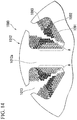
- FIG. 14 shows an example of the winding collapse.
- a first coil 1091 is wound on the winding surface of a winding drum portion 1012a of a tooth 1012, a second coil 1092 is wound over the first coil 1091, and a third coil 1093 is wound over the second coil 1092.
- slack a portion denoted by A in FIG. 14
- winding collapse is caused over all the coils. Since a winding space in a slot 1013 is reduced when the winding collapse is caused, and a coil space factor of a winding wire which can be wound is reduced. Further, there is a possibility that the balance of an armature 1080 may deteriorate when the arrangement of each coil on each tooth 1012 becomes non-uniform.
- the invention provides an armature core that can prevent the winding collapse of coils when a plurality of coils are wound on teeth, an armature using the armature core, and an electric motor using the armature.
- a first aspect of the invention provides an armature core including a plurality of teeth that are provided on an outer periphery of an annular core body and radially extend outward in a radial direction.
- a plurality of coils are wound on a winding drum portion of each tooth; a winding wire of a lower most side of at least a first-layer coil is wound so as to come into close contact with a winding surface of a base end side of the winding drum portion; a second-layer coil, which is to be wound later, is wound so that at least a part of the second-layer coil overlaps the first-layer coil; and a regulating portion, which regulates the positional deviation of the winding wire of the lowermost side of the first-layer coil in an extending direction of the tooth, is provided on at least a part of the winding surface for the first-layer coil on an outer periphery of the winding drum portion.
- the positional deviation of the winding wire of the lowermost side of the first-layer coil in the extending direction of the tooth can be regulated by the regulating portion. Accordingly, it is possible to prevent the winding collapse from being caused by the slack of the first-layer coil that occurs due to the sliding of the first-layer coil, which has been previously wound on the lower side, caused by the second-layer coil wound on the upper side of the first-layer coil. Therefore, since it is possible to increase a winding space in the slot of the armature core, it is possible to improve a coil space factor. Further, since the arrangement of the respective coils of each tooth can be uniformized through the prevention of the winding collapse of the coils, the balance of the armature can be improved.
- a second aspect of the invention provides, in the armature core according to the first aspect of the invention, the regulating portion is provided on at least one side surface of both side surfaces of the winding drum portion in a width direction when seen in an axial direction of the core body.
- the armature core is formed of a laminated body including a plurality of core plates having the same shape, it is possible to form the regulating portions in a state in which the armature core is formed of the laminated body, by only adding shape to be the regulating portion to corresponding portions of each core plate. Accordingly, it is possible to easily form the regulating portions.
- a third aspect of the invention provides, in the armature core according to the first or second aspect of the invention, the regulating portion is formed in the middle of the winding drum portion in the extending direction or on an inner side of the middle of the winding drum portion in the extending direction.
- the winding wire of the lowermost side of the first-layer coil is reliably held at an appropriate position by the position of the step.
- a fourth aspect of the invention provides, in the armature core according to any one of the first to third aspects of the invention, the regulating portion is formed of a step that is provided at an end part of an outer side of the winding surface for the first-layer coil in the extending direction; and with the step as a boundary, a height of the winding surface for the first-layer coil on an inner side in the extending direction is set to be lower than a height of the winding surface on an outer side in the extending direction.
- the position of the winding wire which comes into contact with the step is regulated by the step. So, other winding wires coming into contact with the step are not moved towards the outer side in the extending direction of the winding drum portion. Accordingly, the positional deviation of the other winding wires of the lowermost side is not caused. Therefore, the positional deviation of the winding wires, which are wound on the upper side of the winding wires of the lowermost side, is also not caused. As a result, since it is possible to wind the second or later-layer coil without causing the slack or winding collapse of the first-layer coil, the winding state of the coils is stable.
- a fifth aspect of the invention provides, in the armature core according to the fourth aspect of the invention, a difference in height of the step is set to be equal to or larger than the radius of the winding wire that forms the coil.
- the winding wire of the lowermost side of the first-layer coil is reliably held at an appropriate position by the height of the step.
- a sixth aspect of the invention provides, in the armature core according to any one of the first to third aspects of the invention, the regulating portion is a concave portion to which the winding wire forming the coil is fitted and which is formed at the end part of the outer side of the winding surface for the first-layer coil in the extending direction; and a depth of the concave portion is set to be equal to or smaller than a radius of the winding wire.
- the winding wire when the winding wire is fitted to the concave portion that is formed on the winding surface, the winding wire itself serves a role of the step. Accordingly, it is possible to prevent the positional deviation of the winding wire of the lowermost side of the first-layer coil.
- a seventh aspect of the invention provides an armature in which a plurality of coils are sequentially wound in a concentrated winding manner on the winding drum portion of each tooth of the armature core according to any one of the first to sixth aspects of the invention, and a second or later-layer coil is wound so that at least a part of the second or later-layer coil overlaps a first-layer coil after the first-layer coil is wound so that a winding wire of a lowermost side comes into close contact with the winding surface of the winding drum portion.
- the armature since the armature includes the above-mentioned armature core, it is possible to effectively prevent the winding collapse of the coils. Accordingly, it is possible to improve the coil space factor and to improve balance.
- An eighth aspect of the invention provides an electric motor including the armature according to the seventh aspect of the invention and a magnet that generates a magnetic attractive force or a repelling force with respect to a magnetic field formed by the armature.
- the armature core, the armature, and the electric motor it is possible to prevent the winding collapse of coils in a case in which a plurality of coils are wound on each tooth. Accordingly, it is possible to improve the coil space factor of the armature and to improve the balance of the armature.
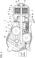
- FIG. 1 is a side view showing the appearance of a motor with a speed reducer to which an electric motor including an armature core according to the invention is applied.
- FIG. 2 is a longitudinal sectional view of the motor with a speed reducer.
- a motor 1 with a speed reducer is used to drive, for example, windshield wipers of an automobile, and includes an electric motor 2 and a speed reduction mechanism 4 that is connected to a rotating shaft 3 of the electric motor 2.
- the electric motor 2 includes a yoke 5 that also functions as a bottomed cylindrical motor housing and an armature 6 that is rotatably provided in the yoke 5.
- a cylinder portion 53 of the yoke 5 is formed in a substantially cylindrical shape, and four segment-type magnets 7 are provided on the inner peripheral surface of the cylinder portion 53. Meanwhile, the magnets 7 are not limited to segment-type magnets and a ring-shaped magnet may be used.
- the sliding bearing 18 has a function to align the rotating shaft 3.
- An outer flange 52 is provided at an opening of the cylinder portion 53, and an end part of a gear housing 23 of the speed reduction mechanism 4 is fixed to the outer flange 52. Accordingly, the electric motor 2 and the speed reduction mechanism 4 are integrally connected to each other.
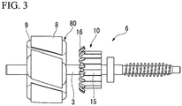
- FIG. 3 is a side view showing the appearance of the armature.
- the armature 6 includes an armature body 80 that is externally fitted and fixed to the rotating shaft 3, and a commutator 10 that is disposed at the other end side of the rotating shaft 3 (the speed reduction mechanism 4 side of the rotating shaft 3).
- the armature body 80 includes an armature core 8 and an armature coil 9 that is wound on the armature core 8.
- the armature core 8 is formed of a laminated core in which core plates punched by pressing or the like and made of a magnetic material are laminated in the axial direction. Meanwhile, a dust core, which is press-molded with soft magnetic powder, can also be used as the armature core 8.
- FIG. 4A is a view showing the armature core in the axial direction and is also a view showing the planar shape of one core plate.
- FIG. 4B is an enlarged view showing a portion B of FIG. 4A together with a coil.
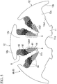
- FIG. 5 is a partially enlarged cross-sectional view of the armature core on which winding wires are wound.
- an “axial direction” is the axial direction of the armature 6, that is, the axial direction of the rotating shaft 3.
- a “radial direction” is the radial direction of the armature 6.
- Inner side in the radial direction is the side facing the rotating shaft 3 in the radial direction of the armature 6, and "outer side in the radial direction” is the side opposite thereto.
- a “circumferential direction” is the circumferential direction of the armature 6 and is the circumferential direction of the rotating shaft 3.
- each armature core is denoted by common reference numeral "8" and an alphabet written in capital added thereto.
- an armature core 8A (8) of the first embodiment includes an annular core body 11.
- a through hole 11a into which the rotating shaft 3 is press-fitted is formed at the center of the core body 11.
- six teeth 12 are radially provided on the outer peripheral portion of the core body 11 at regular intervals in the circumferential direction.
- Each of the teeth 12 is formed in a substantially T shape in a plan view when seen in the axial direction.
- Each of the teeth 12 includes a winding drum portion 12a that radially protrudes from the core body 11 in the radial direction, and a flange portion 12b that extends from the end of the winding drum portion 12a in the circumferential direction and forms the outer periphery of the armature core 8A.
- three coils 91, 92, and 93, which form the armature coil 9 are sequentially wound on the outer periphery of the winding drum portion 12a of each of the teeth 12 in a concentrated winding manner.
- the winding wires 14, which form the first coil 91 are wound on the teeth 12 as a first layer.
- the winding wires 14, which form the second coil 92 are wound on the teeth 12 as a second layer.
- the winding wires 14, which form the third coil 93 are wound on the teeth 12 as a third layer.
- each of the core plates of the armature core 8A is coated with powder, such as an epoxy resin. Accordingly, an insulating film is formed on the surface of each of the core plates. Accordingly, an insulator formed of a resin molding, which is a separate component, is not used.
- the above-mentioned first-layer coil 91 is formed by winding the winding wires 14 on the winding surfaces of the inner side of the winding drum portion 12a of each of the teeth 12 in the radial direction (an extending direction). Further, the second-layer coil 92 is formed by winding the winding wires 14 over the first-layer coil 91 which is previously woundat a position closer to the outside in the radial direction so as to partially overlap the first-layer coil 91. Furthermore, the third-layer coil 93 is formed by winding the winding wires 14 further over the second-layer coil 92 which is previously woundat a position even closer to the outside in the radial direction so as to partially overlap the second-layer coil 92.
- the first-layer coil 91 is wound in a state in which the winding wires 14 of lowermost sides of the first-layer coil 91 come into close contact with base end parts of the winding surfaces of the winding drum portion 12a.
- a regulating portion 12a1 is provided on at least a part of the winding surfaces for the first-layer coil 91 that are formed on the outer periphery of the winding drum portion 12a.
- the regulating portion 12a1 regulates the positional deviation of the winding wires 14 of the lowermost side of the first-layer coil 91 in the radial direction. Since the winding drum portion 12a of each of the teeth 12 has a rectangular cross-sectional shape, the regulating portion 12a1 may be provided on the winding surface corresponding to at least one side of the rectangular cross-sectional shape (one of four winding surfaces).
- the regulating portions 12a1 are provided on both side surfaces of the winding drum portion 12a in a width direction among the four winding surfaces corresponding to the four sides of the rectangular cross-sectional shape. Meanwhile, the regulating portions 12a1 are provided so as to be continued in the axial direction.
- the regulating portion 12a1 of the armature core 8A of this embodiment is formed by a step 12a1 (that is denoted by the same reference numeral as the regulating portion) that is provided at an end part of the outer side of the winding surface for the first-layer coil 91 in the radial direction. Further, with the step 12a1 as a boundary, a height of the winding surface for the first-layer coil 91 on an inner side in the radial direction is set to be lower than a height of the winding surface for other coils 92 and 93 on an outer side in the radial direction. That is, the step 12a1 is formed by changing the width dimension of the tooth 12.
- the length L2 of the winding surface for the first-layer coil 91, on which the step 12a1 is provided, in the extending direction of the tooth 12 (the winding drum portion 12a) is set to a half or less of the length L1 of the entire winding surface in the extending direction of the tooth 12.
- the step 12a1 is formed in the middle of the tooth 12 (the winding drum portion 12a) in the extending direction or on an inner side of the middle of the tooth 12 in the extending direction.
- the height (a difference in height) H of the step 12a1 is set to be equal to or larger than the radius h of the winding wire 14 that forms the coil 91.
- the armature core 8A is formed as described above, it is possible to form the armature coil 9, which includes three coils 91, 92, and 93 without winding collapse, by sequentially winding the winding wires 14 of the first coil 91, the winding wires 14 of the second coil 92, and the winding wires 14 of the third coil 93 on the winding drum portion 12a of each of the teeth 12 of the armature core 8A.
- the winding wires 14 of the first-layer first coil 91 are wound so as to come into close contact with the winding surfaces of the inner side in the radial direction of the drum part 12a of the tooth 12.
- the position of the winding wire 14, which comes into direct contact with the step 12a1 among the winding wires 14 of the lowermost side of the first-layer coil 91 is regulated by the step 12a1 so that the winding wire 14 is not moved towards the outside in the radial direction.
- the positions of the other winding wires 14 of the lowermost side are also regulated so as to follow the position of the winding wire 14 in the same way.
- the second layer coil 92 and the third-layer coil 93 are sequentially wound while partially overlapping the coil that is positioned therebeneath.
- the armature coil 9 is completed.
- the positions of the winding wires 14 of the lowermost side of the first-layer coil 91 are regulated by the step 12a1. For this reason, since the slack of the winding wires 14 by the sliding of the winding wire 14 is not caused and the winding collapse of all the coils will not occur, thus the winding states of the coils 91, 92, and 93 are stable.
- the steps 12a1 as the regulating portions are formed on both side surfaces of each tooth 12 in the width direction, it is possible to easily form the regulating portions by only adding the steps 12a1 to be the regulating portions, to corresponding portions of each of the core plates that form the armature core 8A. Moreover, it is possible to reliably hold the winding wires 14 of the lowermost side of the first-layer coil 91 at appropriate positions, that is, to prevent the winding wires 14 of the lowermost side of the first-layer coil 91 from getting onto the step 12a1 by the setting of a position where the step 12a1 is to be provided (the position regulated by the length L2) or a difference H in height. For this reason, it is possible to reliably prevent the winding collapse of the coils 91, 92, and 93.
- eighteen segments 15, which are made of a conductive material, are mounted on the outer peripheral surface of the commutator 10 that is externally fitted and fixed to a side of the rotating shaft 3 closer to the other end side of the rotating shaft 3 (the speed reduction mechanism 4 side of the rotating shaft 3) than the armature core 8.
- the segment 15 is formed of a plate-like metal piece that is long in the axial direction.
- the segments 15 are fixed in parallel at regular intervals in the circumferential direction in a state in which the segments 15 are insulated from each other.
- the electric motor 2 is formed as a so-called 4-pole, 6-slot, 18-segment electric motor of which the number of magnetic poles is set to four, the number of slots 13 is set to six, and the number of segments 15 is set to eighteen.
- a riser 16 which is bent so as to be folded back toward the outer diameter side, is molded integrally with an end part of each segment 15 facing the armature core 8. Terminal portions of the armature coil 9 are wound around the risers 16 and are fixed to the risers 16 by fusing or the like. Accordingly, the segment 15 and the armature coil 9 corresponding thereto are electrically connected to each other.
- connecting wires 17 are wound around the risers 16 corresponding to the segments 15 having the same electric potential, and the connecting wires 17 are fixed to the risers 16 by fusing.
- the connecting wires 17 are used to allow the segments 15, which have the same electric potential, to short-circuit.
- the connecting wires 17 are routed between the commutator 10 and the armature core 8.
- the commutator 10 having the above-mentioned structure faces the gear housing 23 of the speed reduction mechanism 4.
- a gear group 41 of the speed reduction mechanism 4 is housed in the gear housing 23.
- a brush housing portion 22 is molded integrally with the side of the gear housing 23 facing the electric motor 2.
- the commutator 10 of the electric motor 2 faces the brush housing portion 22.
- a brush 21 is housed in the brush housing portion 22 so as to freely protrude/recede through a holder stay or a brush holder (not shown).
- the brush 21 is used to supply power from an external power source (for example, a battery mounted on an automobile, or the like) to the commutator 10.
- the brush 21 is biased toward the commutator 10 by a spring (not shown), and an end of the brush 21 comes into sliding contact with the segments 15.
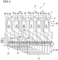
- FIG. 6 is a development view of the armature. A gap between the adjacent teeth corresponds to the slot. Meanwhile, each segment 15, each tooth 12, and the formed armature coil 9 will be described while being denoted by reference numerals in FIG. 6 .
- a U phase, a V phase, and a W phase are assigned to each tooth 12 in this order in the circumferential direction. That is, the first tooth 12 and the fourth tooth 12 correspond to a U phase, the second tooth 12 and the fifth tooth 12 correspond to a V phase, and the third tooth 12 and the sixth tooth 12 correspond to a W phase.
- the position corresponding to the first is regarded as a position corresponding to the first tooth 12.
- a direction in which the winding wire 14 is wound on each tooth 12 clockwise will be described as a forward direction and a direction in which the winding wire 14 is wound on each tooth 12 counterclockwise will be described as a reverse direction.
- the winding wire 14 is led into the slot 13 between the first and sixth teeth 12 existing near the first segment 15. Further, in a case in which the winding wire 14 is wound on each of the teeth 12 n times (n is a natural number and a multiple of 3), the winding wire 14 is wound on the first tooth 12 n/3 times in the forward direction in a concentrated winding manner.
- the winding wire 14 is led out of the slot 13 between the first and second teeth 12, and is wound around the riser 16 of the second segment 15 adjacent to the first segment 15. Then, a winding terminal end 14b is connected to the second segment 15. Accordingly, a U-phase first coil 91, which is wound on the first tooth 12 in the forward direction, is formed between the first and second segments 15.
- the winding wire 14 of which the winding start end 14a is wound around the riser 16 of the fifth segment 15 is led into the slot 13 between the first and second teeth 12. Then, the winding wire 14 is wound on the first tooth 12 n/3 times in the reverse direction in a concentrated winding manner.
- the winding wire 14 is led out of the slot 13 between the first and sixth teeth 12, and is wound around the riser 16 of the sixth segment 15 adjacent to the fifth segment 15. Then, the winding terminal end 14b is connected to the sixth segment 15. Accordingly, a "-U"-phase second coil 92, which is wound on the first tooth 12 in the reverse direction, is formed between the fifth and sixth segments 15.
- the winding wire 14 of which the winding start end 14a is wound around the riser 16 of the sixth segment 15 is led into the slot 13 between the first and second teeth 12. Then, the winding wire 14 is wound on the first tooth 12 n/3 times in the reverse direction in a concentrated winding manner.
- the winding wire 14 is led out of the slot 13 between the first and sixth teeth 12, and is wound around the riser 16 of the seventh segment 15 adjacent to the sixth segment 15. Then, the winding terminal end 14b is connected to the seventh segment 15. Accordingly, a "-U"-phase third coil 93, which is wound on the first tooth 12 in the reverse direction, is formed between the sixth and seventh segments 15.
- an n-time winding armature coil 9 which includes the U-phase first coil 91, the "-U"-phase second coil 92, and the "-U"-phase third coil 93, is formed on the first tooth 12 corresponding to a U phase.
- the U-phase first coil 91 is formed of the winding wire 14 that is wound n/3 times in the forward direction; and the "-U"-phase second coil 92 and the "-U"-phase third coil 93 are formed of the winding wires 14 that are wound n/3 times in the reverse direction.
- the armature coil 9 having a 3-phase structure including the first coil 91, the second coil 92, and the third coil 93 is formed on the armature core 8. Accordingly, the coils 91 to 93, which correspond to a U phase, a "-W” phase, a "-W” phase, a V phase, a "-U” phase, a “-U” phase, a W phase, a "-V” phase, and a "-V” phase, are electrically and sequentially connected in this order between the adjacent segments 15.
- the coils 91 to 93 which correspond to a U phase, a "-W” phase, a “-W” phase, a V phase, a "-U” phase, a "-U” phase, a W phase, a "-V” phase, and a "-V” phase, may be electrically and sequentially connected in this order between the adjacent segments 15.
- the U-phase first coil 91 short-circuits. Then, current flows in the "-U"-phase second coil 92 in the reverse direction (a counterclockwise direction in FIG. 6 ), and current flows in the "-U"-phase third coil 93 in the forward direction (a clockwise direction in FIG. 6 ). That is, since the direction of current flowing in the second coil 92 and the direction of current flowing in the third coil 93 are opposite to each other, a magnetic field is cancelled and torque is not generated with the magnet 7.
- a magnetic field is formed on each of the second, third, fifth, and sixth teeth 12.
- the directions of these magnetic fields are in series in the circumferential direction. For this reason, a magnetic attractive force or a repelling force between the magnetic field formed on each tooth 12 and the motor magnet 7 acts in the same direction at symmetrical positions with respect to the rotating shaft 3 as a center. Then, the rotating shaft 3 is rotated by the magnetic attractive force or the repelling force.
- FIG. 7 is a development view of an armature of a first modification of the first embodiment.
- an electric motor 202 of this modification is formed of a so-called 4-pole, 6-slot, 12-segment electric motor of which the number of magnetic poles is set to four, the number of slots 13 is set to six, and the number of segments 15 is set to twelve.
- the armature coil 9 having a 3-phase structure including three coils 91 to 93, that is, the first coil 91, the second coil 92, and the third coil 93 is formed on the armature core 8 that forms the armature of the first embodiment.
- an armature coil 209 having a 3-phase structure including two coils, that is, a first coil 91 and a second coil 92 is formed on an armature core 8 that forms an armature of the first modification.
- the first modification is different from the above-mentioned first embodiment.
- a U phase, a V phase, and a W phase are assigned to each tooth 12 in this order in the circumferential direction. That is, the first tooth 12 and the fourth tooth 12 correspond to a U phase, the second tooth 12 and the fifth tooth 12 correspond to a V phase, and the third tooth 12 and the sixth tooth 12 correspond to a W phase.
- the position corresponding to the first is a position corresponding to the first tooth 12.
- the segments 15, which have the same electric potential, are short-circuited by connecting wires 17. Meanwhile, in FIG. 7 , a direction in which the winding wire 14 is wound on each tooth 12 clockwise will be described as a forward direction and a direction in which the winding wire 14 is wound on each tooth 12 counterclockwise will be described as a reverse direction.
- the winding wire 14 is led into the slot 13 between the first and sixth teeth 12 existing near the first segment 15. Further, in a case in which the winding wire 14 is wound on each of the teeth 12 n times (n is a natural number and a multiple of 2), the winding wire 14 is wound on the first tooth 12 n/2 times in the forward direction in a concentrated winding manner.
- the winding wire 14 is led out of the slot 13 between the first and second teeth 12, and is wound around the riser 16 of the second segment 15 adjacent to the first segment 15. Then, a winding terminal end 14b is connected to the second segment 15. Accordingly, a U-phase first coil 291, which is wound on the first tooth 12 in the forward direction, is formed between the first and second segments 15.
- the winding wire 14 of which the winding start end 14a is wound around the riser 16 of the fourth segment 15 is led into the slot 13 between the first and second teeth 12. Then, the winding wire 14 is wound on the first tooth 12 n/2 times in the reverse direction in a concentrated winding manner.
- the winding wire 14 is led out of the slot 13 between the first and sixth teeth 12, and is wound around the riser 16 of the fifth segment 15 adjacent to the fourth segment 15. Then, the winding terminal end 14b is connected to the fifth segment 15. Accordingly, a "-U"-phase second coil 292, which is wound on the first tooth 12 in the reverse direction, is formed between the fourth and fifth segments 15.
- an n-time winding armature coil 209 which includes the U-phase first coil 91 and the "-U"-phase second coil 92, is formed on the first tooth 12 corresponding to a U phase.
- the U-phase first coil 91 is formed of the winding wire 14 that is wound n/2 times in the forward direction; and the "-U"-phase second coil 92 is formed of the winding wire 14 that is wound n/2 times in the reverse direction.
- the armature coil 209 having a 3-phase structure including the first coil 91 and the coil 292 is formed on the armature core 8. Accordingly, the coils 91 and 92, which correspond to a U phase, a "-W” phase, a V phase, a "-U” phase, a W phase, and a "-V” phase, are electrically and sequentially connected in this order between the adjacent segments 15.
- the coils 91 and 92 which correspond to a U phase, a "-W” phase, a V phase, a "-U” phase, a W phase, and a "-V” phase, may be electrically and sequentially connected in this order between the adjacent segments 15.
- FIG. 8 is a development view of an armature of a second modification of the first embodiment.
- the number of magnetic poles has been four (the number of the pairs of magnetic poles has been two) in the first modification.
- the number of magnetic poles is six (the number of the pairs of magnetic poles is three) in the second modification.
- the number of teeth 12 of an armature core 8, which has been six is changed to nine.
- the number of segments 15 of a commutator 310, which has been twelve, is changed to eighteen.
- the second modification is different from the above-mentioned first modification.
- the first coil 91 and the second coil 92 are sequentially wound on each tooth 12.
- the winding wire 14 is continuously wound on the teeth 12 corresponding to the same phase.
- the above-mentioned first modification and the second modification are different from each other. That is, in the second modification, the winding wire 14, which is wound on one tooth 12, is not connected to the segment 15 and is wound on the teeth 12 corresponding to the same phase (for example, the first tooth 12, the fourth tooth 12, and the seventh tooth 12). After the winding wire 14 is wound on all the teeth 12 corresponding to the same phase and forms the coils 91 and 92, then a winding terminal end of the winding wire 14 is connected to a predetermined segment 15.
- FIG. 9 is a view showing an armature core of a second embodiment in an axial direction.
- convex portions 12a2 are provided as regulating portions on both side surfaces of a winding drum portion 12a of each tooth 12 in a width direction.
- the convex portion 12a2 also has the same function as the step 12a1 of the first embodiment.
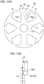
- FIG. 10A is a view showing an armature core of a third embodiment and is a view showing the armature core in an axial direction.
- FIG. 10B is an enlarged view of a portion C of FIG. 10A .
- concave portions 12a3, to which a winding wire 14 forming a first-layer coil 91 is fitted, are provided as regulating portions on both side surfaces of a winding drum portion 12a of each tooth 12 in a width direction.
- the depth d of the concave portion 12a3 is set to be equal to or smaller than the radius h of the winding wire 14.
- the winding wire 14 (14C) when the winding wire 14 (14C) is fitted to the concave portions 12a3 that are formed on the winding surfaces, the winding wire 14C itself serves a role of the step of the first embodiment. For this reason, it is possible to prevent the positional deviation of the lowermost winding wires of the first-layer coil.
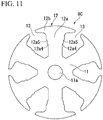
- FIG. 11 is a view showing an armature core of a fourth embodiment in an axial direction.
- first steps 12a4 and second steps 12a5 are provided as regulating portions in two steps on both side surfaces of a winding drum portion 12a of each tooth 12 in a width direction so that the positions of the steps deviate outward from the inside in the radial direction.
- the first step 12a4 functions to prevent the deviation of a first-layer coil 91
- the second step 12a5 functions to prevent the deviation of a second-layer coil 92.
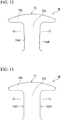
- FIG. 12 is a view showing an armature core of a fifth embodiment in an axial direction.
- a plurality of concave portions 12a6 having a size which allows the winding wire 14 (see FIG. 5 ) to be fitted thereto are continuously provided as regulating portions on both side surfaces of a winding drum portion 12a of each tooth 12 in a width direction. It is possible to obtain the same effect as the first embodiment by providing the plurality of concave portions 12a6 as described above.
- FIG. 13 is a view showing an armature core of a sixth embodiment in an axial direction.
- wire materials 12a7 having the same diameter as the winding wire 14 (see FIG. 5 ) are fixed to both side surfaces of a winding drum portion 12a of each tooth 12 in a width direction as a regulating portion by means, such as welding or adhesion.
- the wire materials 12a7 also has the same function as the step 12a1 of the first embodiment.
- the armature core, the armature, and the electric motor it is possible to prevent the winding collapse of coils when a plurality of coils are wound on each tooth. Accordingly, it is possible to improve the coil space factor of the armature and to improve the balance of the armature.
Landscapes
- Engineering & Computer Science (AREA)
- Power Engineering (AREA)
- Dc Machiner (AREA)
- Windings For Motors And Generators (AREA)
- Iron Core Of Rotating Electric Machines (AREA)
Abstract
Description
- The present invention relates to an armature core where a plurality of coils are wound on each tooth, an armature where a plurality of coils are wound on the armature core, and an electric motor using the armature.
- Priority is claimed on
Japanese Patent Application No. 2014-042659, filed March 05, 2014 - For example, a DC motor with a brush, in which motor magnets are disposed on the inner peripheral surface of a bottomed cylindrical yoke and an armature is rotatably provided on the inside of the motor magnets in a radial direction, is known as an electric motor (for example, see PTL 1).
- The armature includes an armature core, armature coils, and a commutator.
The armature core includes a plurality of teeth that are provided on the outer periphery of an annular core body externally fitted and fixed to a rotating shaft and radially extend outward in the radial direction. The armature coil is wound on each tooth of the armature core via a slot between the teeth. The commutator is provided on the rotating shaft so as to rotate integrally with the armature core. - The commutator includes a plurality of segments that are disposed side by side in a circumferential direction in a state in which the segments are insulated from each other. Terminal portions of the respective armature coils are connected to these segments. Further, a plurality of brushes come into sliding contact with the segments. When DC current is supplied to each armature coil through the segment by the brushes, the armature and the rotating shaft are rotated by a magnetic attractive force or a repelling force that is generated between a magnetic field formed on the armature core and the motor magnets. Since the segments with which the brushes come into sliding contact are sequentially changed by the rotation of the armature and the rotating shaft, the switching of the direction of current flowing in the armature coil, that is, so-called rectification is performed. As a result, the armature is continuously rotated and a rotational output is taken out of the rotating shaft.
- Incidentally, when the commutator rotates, the brushes repeatedly come into contact with the segments and are repeatedly separated from the segments. For this reason, when a voltage between the segments is high, electric discharge may be generated at the time of the separation of the brushes from the segments. As means for preventing this, there is, for example, a method that sets the number of the segments of the commutator to two or three times the number of the teeth of the armature core and lowers the voltage between the segments. In such a case, a plurality of winding wires are used to form a plurality of coils on each tooth of the armature core.
- Here, in a case in which a plurality of coils are wound on each tooth, the coils are sequentially wound. For example, a second coil is wound after a first coil is wound. In a case in which there is a third coil, the third coil is wound after the second coil is wound. In this case, the second (second-layer) coil is wound such that at least a part of the second (second-layer) coil overlaps the first (first-layer) coil.
- [PTL1]
Japanese Unexamined Patent Application, Publication No. 2007-228754 - When the coil wound on the lower side slides due to the coil wound on the upper side, the slack of the lower coil can be caused. For this reason, winding collapse may be caused.
FIG. 14 shows an example of the winding collapse. - In
FIG. 14 , afirst coil 1091 is wound on the winding surface of awinding drum portion 1012a of atooth 1012, asecond coil 1092 is wound over thefirst coil 1091, and athird coil 1093 is wound over thesecond coil 1092. However, when slack (a portion denoted by A inFIG. 14 ) occurs on the lowermost side of thefirst coil 1091, winding collapse is caused over all the coils. Since a winding space in aslot 1013 is reduced when the winding collapse is caused, and a coil space factor of a winding wire which can be wound is reduced. Further, there is a possibility that the balance of anarmature 1080 may deteriorate when the arrangement of each coil on eachtooth 1012 becomes non-uniform. - The invention provides an armature core that can prevent the winding collapse of coils when a plurality of coils are wound on teeth, an armature using the armature core, and an electric motor using the armature.
- A first aspect of the invention provides an armature core including a plurality of teeth that are provided on an outer periphery of an annular core body and radially extend outward in a radial direction. A plurality of coils are wound on a winding drum portion of each tooth; a winding wire of a lower most side of at least a first-layer coil is wound so as to come into close contact with a winding surface of a base end side of the winding drum portion; a second-layer coil, which is to be wound later, is wound so that at least a part of the second-layer coil overlaps the first-layer coil; and a regulating portion, which regulates the positional deviation of the winding wire of the lowermost side of the first-layer coil in an extending direction of the tooth, is provided on at least a part of the winding surface for the first-layer coil on an outer periphery of the winding drum portion.
- According to the armature core, the positional deviation of the winding wire of the lowermost side of the first-layer coil in the extending direction of the tooth can be regulated by the regulating portion. Accordingly, it is possible to prevent the winding collapse from being caused by the slack of the first-layer coil that occurs due to the sliding of the first-layer coil, which has been previously wound on the lower side, caused by the second-layer coil wound on the upper side of the first-layer coil. Therefore, since it is possible to increase a winding space in the slot of the armature core, it is possible to improve a coil space factor. Further, since the arrangement of the respective coils of each tooth can be uniformized through the prevention of the winding collapse of the coils, the balance of the armature can be improved.
- A second aspect of the invention provides, in the armature core according to the first aspect of the invention, the regulating portion is provided on at least one side surface of both side surfaces of the winding drum portion in a width direction when seen in an axial direction of the core body.
- According to the above-mentioned structure, in a case in which the armature core is formed of a laminated body including a plurality of core plates having the same shape, it is possible to form the regulating portions in a state in which the armature core is formed of the laminated body, by only adding shape to be the regulating portion to corresponding portions of each core plate. Accordingly, it is possible to easily form the regulating portions.
- A third aspect of the invention provides, in the armature core according to the first or second aspect of the invention, the regulating portion is formed in the middle of the winding drum portion in the extending direction or on an inner side of the middle of the winding drum portion in the extending direction.
- According to the above-mentioned structure, the winding wire of the lowermost side of the first-layer coil is reliably held at an appropriate position by the position of the step.
- A fourth aspect of the invention provides, in the armature core according to any one of the first to third aspects of the invention, the regulating portion is formed of a step that is provided at an end part of an outer side of the winding surface for the first-layer coil in the extending direction; and with the step as a boundary, a height of the winding surface for the first-layer coil on an inner side in the extending direction is set to be lower than a height of the winding surface on an outer side in the extending direction.
- According to the above-mentioned structure, among the winding wires of the lowermost side of the first-layer coil wound on the winding surface for the first-layer coil of the inner side in the radial direction so as to come into close contact with the winding surface for the first-layer coil, the position of the winding wire which comes into contact with the step is regulated by the step. So, other winding wires coming into contact with the step are not moved towards the outer side in the extending direction of the winding drum portion. Accordingly, the positional deviation of the other winding wires of the lowermost side is not caused. Therefore, the positional deviation of the winding wires, which are wound on the upper side of the winding wires of the lowermost side, is also not caused. As a result, since it is possible to wind the second or later-layer coil without causing the slack or winding collapse of the first-layer coil, the winding state of the coils is stable.
- A fifth aspect of the invention provides, in the armature core according to the fourth aspect of the invention, a difference in height of the step is set to be equal to or larger than the radius of the winding wire that forms the coil.
- According to the above-mentioned structure, according to the armature core, the winding wire of the lowermost side of the first-layer coil is reliably held at an appropriate position by the height of the step.
- A sixth aspect of the invention provides, in the armature core according to any one of the first to third aspects of the invention, the regulating portion is a concave portion to which the winding wire forming the coil is fitted and which is formed at the end part of the outer side of the winding surface for the first-layer coil in the extending direction; and a depth of the concave portion is set to be equal to or smaller than a radius of the winding wire.
- According to the above-mentioned structure, when the winding wire is fitted to the concave portion that is formed on the winding surface, the winding wire itself serves a role of the step. Accordingly, it is possible to prevent the positional deviation of the winding wire of the lowermost side of the first-layer coil.
- A seventh aspect of the invention provides an armature in which a plurality of coils are sequentially wound in a concentrated winding manner on the winding drum portion of each tooth of the armature core according to any one of the first to sixth aspects of the invention, and a second or later-layer coil is wound so that at least a part of the second or later-layer coil overlaps a first-layer coil after the first-layer coil is wound so that a winding wire of a lowermost side comes into close contact with the winding surface of the winding drum portion.
- According to the above-mentioned structure, since the armature includes the above-mentioned armature core, it is possible to effectively prevent the winding collapse of the coils. Accordingly, it is possible to improve the coil space factor and to improve balance.
- An eighth aspect of the invention provides an electric motor including the armature according to the seventh aspect of the invention and a magnet that generates a magnetic attractive force or a repelling force with respect to a magnetic field formed by the armature.
- According to the above-mentioned structure, it is possible to provide a high-quality electric motor having a high coil space factor.
- According to the armature core, the armature, and the electric motor, it is possible to prevent the winding collapse of coils in a case in which a plurality of coils are wound on each tooth. Accordingly, it is possible to improve the coil space factor of the armature and to improve the balance of the armature.
-
-
FIG. 1 is a side view showing the appearance of a motor with a speed reducer of a first embodiment of the invention. -
FIG. 2 is a longitudinal sectional view of the motor with a speed reducer of the first embodiment of the invention. -
FIG. 3 is a side view of an armature of the first embodiment of the invention. -
FIG. 4A is a view showing an armature core of the first embodiment of the invention and is a view showing the armature core in an axial direction (corresponding to a plan view of a core plate). -
FIG. 4B is a view showing the armature core of the first embodiment of the invention and is an enlarged view of a portion B ofFIG. 4A . -
FIG. 5 is a partial cross-sectional view of the armature of the first embodiment of the invention. -
FIG. 6 is a development view of the armature of the first embodiment of the invention. -
FIG. 7 is a development view of an armature of a first modification of the first embodiment of the invention. -
FIG. 8 is a development view of an armature of a second modification of the first embodiment of the invention. -
FIG. 9 is a view showing an armature core of a second embodiment of the invention in an axial direction (corresponding to a plan view of a core plate). -
FIG. 10A is a view showing an armature core of a third embodiment of the invention and is a view showing the armature core in an axial direction. -
FIG. 10B is a view showing the armature core of the third embodiment of the invention and is an enlarged view of a portion C ofFIG. 10A . -
FIG. 11 is a view showing an armature core of a fourth embodiment of the invention in an axial direction (corresponding to a plan view of a core plate). -
FIG. 12 is a partial plan view of an armature core of a fifth embodiment of the invention that is seen in an axial direction (corresponding to a plan view of a core plate). -
FIG. 13 is a partial sectional view of an armature core of a sixth embodiment of the invention that is seen in an axial direction (corresponding to a plan view of a core plate). -
FIG. 14 is a partial sectional view of an armature in the related art. - Next, a first embodiment of the invention will be described with reference to
FIGS. 1 to 6 . -
FIG. 1 is a side view showing the appearance of a motor with a speed reducer to which an electric motor including an armature core according to the invention is applied.FIG. 2 is a longitudinal sectional view of the motor with a speed reducer. - As shown in
FIGS. 1 and2 , amotor 1 with a speed reducer is used to drive, for example, windshield wipers of an automobile, and includes anelectric motor 2 and aspeed reduction mechanism 4 that is connected to arotating shaft 3 of theelectric motor 2. Theelectric motor 2 includes ayoke 5 that also functions as a bottomed cylindrical motor housing and anarmature 6 that is rotatably provided in theyoke 5. - A
cylinder portion 53 of theyoke 5 is formed in a substantially cylindrical shape, and four segment-type magnets 7 are provided on the inner peripheral surface of thecylinder portion 53. Meanwhile, themagnets 7 are not limited to segment-type magnets and a ring-shaped magnet may be used. - A bearing
housing 19, which protrudes outward in an axial direction, is formed at a radially central portion of a bottom wall (an end part) 51 of theyoke 5, and a slidingbearing 18, by which one end of therotating shaft 3 is rotatably supported, is provided in the bearinghousing 19. The slidingbearing 18 has a function to align therotating shaft 3. - An
outer flange 52 is provided at an opening of thecylinder portion 53, and an end part of agear housing 23 of thespeed reduction mechanism 4 is fixed to theouter flange 52. Accordingly, theelectric motor 2 and thespeed reduction mechanism 4 are integrally connected to each other. -
FIG. 3 is a side view showing the appearance of the armature. - As shown in
FIGS. 2 and3 , thearmature 6 includes anarmature body 80 that is externally fitted and fixed to therotating shaft 3, and acommutator 10 that is disposed at the other end side of the rotating shaft 3 (thespeed reduction mechanism 4 side of the rotating shaft 3). - The
armature body 80 includes anarmature core 8 and anarmature coil 9 that is wound on thearmature core 8. Thearmature core 8 is formed of a laminated core in which core plates punched by pressing or the like and made of a magnetic material are laminated in the axial direction. Meanwhile, a dust core, which is press-molded with soft magnetic powder, can also be used as thearmature core 8. -
FIG. 4A is a view showing the armature core in the axial direction and is also a view showing the planar shape of one core plate.FIG. 4B is an enlarged view showing a portion B ofFIG. 4A together with a coil. Further,FIG. 5 is a partially enlarged cross-sectional view of the armature core on which winding wires are wound. - Here, terms about directions to be used will be defined below. First, an "axial direction" is the axial direction of the
armature 6, that is, the axial direction of therotating shaft 3. A "radial direction" is the radial direction of thearmature 6. "Inner side in the radial direction" is the side facing therotating shaft 3 in the radial direction of thearmature 6, and "outer side in the radial direction" is the side opposite thereto. Further, a "circumferential direction" is the circumferential direction of thearmature 6 and is the circumferential direction of therotating shaft 3. - Furthermore, in a case of describing armature cores irrespective of a small difference in the shape, the armature cores are denoted by common reference numeral "8". In a case of describing armature cores of embodiments by distinguishing from each other through a small difference in the shape, each armature core is denoted by common reference numeral "8" and an alphabet written in capital added thereto.
- As shown in
FIG. 4A , anarmature core 8A (8) of the first embodiment includes anannular core body 11. A throughhole 11a into which therotating shaft 3 is press-fitted is formed at the center of thecore body 11. Further, sixteeth 12 are radially provided on the outer peripheral portion of thecore body 11 at regular intervals in the circumferential direction. Each of theteeth 12 is formed in a substantially T shape in a plan view when seen in the axial direction. Each of theteeth 12 includes a windingdrum portion 12a that radially protrudes from thecore body 11 in the radial direction, and aflange portion 12b that extends from the end of the windingdrum portion 12a in the circumferential direction and forms the outer periphery of thearmature core 8A. - According to this structure, six
slots 13 are formed amongadjacent teeth 12. Further, windingwires 14 coated with enamel pass through theseslots 13 and the windingwires 14 are wound on the outer peripheries of the windingdrum portions 12a of theteeth 12 in a concentrated winding manner as shown inFIG. 5 , so that thearmature coil 9 is formed (the detail of a method of forming thearmature coil 9 will be described below). - In this case, as shown in
FIG. 5 , threecoils armature coil 9, are sequentially wound on the outer periphery of the windingdrum portion 12a of each of theteeth 12 in a concentrated winding manner. First, the windingwires 14, which form thefirst coil 91, are wound on theteeth 12 as a first layer. Over that, the windingwires 14, which form thesecond coil 92, are wound on theteeth 12 as a second layer. Finally, the windingwires 14, which form thethird coil 93, are wound on theteeth 12 as a third layer. Meanwhile, before thecoils armature core 8A is coated with powder, such as an epoxy resin. Accordingly, an insulating film is formed on the surface of each of the core plates. Accordingly, an insulator formed of a resin molding, which is a separate component, is not used. - The above-mentioned first-
layer coil 91 is formed by winding the windingwires 14 on the winding surfaces of the inner side of the windingdrum portion 12a of each of theteeth 12 in the radial direction (an extending direction). Further, the second-layer coil 92 is formed by winding the windingwires 14 over the first-layer coil 91 which is previously woundat a position closer to the outside in the radial direction so as to partially overlap the first-layer coil 91. Furthermore, the third-layer coil 93 is formed by winding the windingwires 14 further over the second-layer coil 92 which is previously woundat a position even closer to the outside in the radial direction so as to partially overlap the second-layer coil 92. Here, the first-layer coil 91 is wound in a state in which the windingwires 14 of lowermost sides of the first-layer coil 91 come into close contact with base end parts of the winding surfaces of the windingdrum portion 12a. - When the winding
wires 14 forming therespective coils wires 14 of the first-layer coil 91 slide on the windingdrum portion 12a due to a force generated while winding the second-layer coil 92 on the first-layer coil 91 as described above and cause the slack. For this reason, there is a concern that winding collapse may occur on all the coils. - Here, in the
armature core 8A of this embodiment, as shown inFIGS. 4A and5 , a regulating portion 12a1 is provided on at least a part of the winding surfaces for the first-layer coil 91 that are formed on the outer periphery of the windingdrum portion 12a. The regulating portion 12a1 regulates the positional deviation of the windingwires 14 of the lowermost side of the first-layer coil 91 in the radial direction. Since the windingdrum portion 12a of each of theteeth 12 has a rectangular cross-sectional shape, the regulating portion 12a1 may be provided on the winding surface corresponding to at least one side of the rectangular cross-sectional shape (one of four winding surfaces). However, here, considerating that thearmature core 8A is a laminated core, when seen in the axial direction, the regulating portions 12a1 are provided on both side surfaces of the windingdrum portion 12a in a width direction among the four winding surfaces corresponding to the four sides of the rectangular cross-sectional shape. Meanwhile, the regulating portions 12a1 are provided so as to be continued in the axial direction. - The regulating portion 12a1 of the
armature core 8A of this embodiment is formed by a step 12a1 (that is denoted by the same reference numeral as the regulating portion) that is provided at an end part of the outer side of the winding surface for the first-layer coil 91 in the radial direction. Further, with the step 12a1 as a boundary, a height of the winding surface for the first-layer coil 91 on an inner side in the radial direction is set to be lower than a height of the winding surface forother coils tooth 12. - As shown in
FIG. 4A , the length L2 of the winding surface for the first-layer coil 91, on which the step 12a1 is provided, in the extending direction of the tooth 12 (the windingdrum portion 12a) is set to a half or less of the length L1 of the entire winding surface in the extending direction of thetooth 12. In other words, the step 12a1 is formed in the middle of the tooth 12 (the windingdrum portion 12a) in the extending direction or on an inner side of the middle of thetooth 12 in the extending direction. - Further, as shown in
FIG. 4B , the height (a difference in height) H of the step 12a1 is set to be equal to or larger than the radius h of the windingwire 14 that forms thecoil 91. - Since the
armature core 8A is formed as described above, it is possible to form thearmature coil 9, which includes threecoils wires 14 of thefirst coil 91, the windingwires 14 of thesecond coil 92, and the windingwires 14 of thethird coil 93 on the windingdrum portion 12a of each of theteeth 12 of thearmature core 8A. - That is, as shown in
FIG. 5 , the windingwires 14 of the first-layerfirst coil 91 are wound so as to come into close contact with the winding surfaces of the inner side in the radial direction of thedrum part 12a of thetooth 12. In this case, the position of the windingwire 14, which comes into direct contact with the step 12a1, among the windingwires 14 of the lowermost side of the first-layer coil 91 is regulated by the step 12a1 so that the windingwire 14 is not moved towards the outside in the radial direction. Further, the positions of the other windingwires 14 of the lowermost side are also regulated so as to follow the position of the windingwire 14 in the same way. - Then, after the first-
layer coil 91 is wound, thesecond layer coil 92 and the third-layer coil 93 are sequentially wound while partially overlapping the coil that is positioned therebeneath. As a result, thearmature coil 9 is completed. In this case, even when the second-layer coil 92 or the third-layer coil 93 is wound, the positions of the windingwires 14 of the lowermost side of the first-layer coil 91 are regulated by the step 12a1. For this reason, since the slack of the windingwires 14 by the sliding of the windingwire 14 is not caused and the winding collapse of all the coils will not occur, thus the winding states of thecoils slots 13 of thearmature core 8A is increased, a coil space factor is improved. Further, since the arrangement of therespective coils tooth 12 is uniformized through the prevention of the winding collapse of thecoils armature 6 can be improved. - Furthermore, in a case in which the steps 12a1 as the regulating portions are formed on both side surfaces of each
tooth 12 in the width direction, it is possible to easily form the regulating portions by only adding the steps 12a1 to be the regulating portions, to corresponding portions of each of the core plates that form thearmature core 8A. Moreover, it is possible to reliably hold the windingwires 14 of the lowermost side of the first-layer coil 91 at appropriate positions, that is, to prevent the windingwires 14 of the lowermost side of the first-layer coil 91 from getting onto the step 12a1 by the setting of a position where the step 12a1 is to be provided (the position regulated by the length L2) or a difference H in height. For this reason, it is possible to reliably prevent the winding collapse of thecoils - Next, another structure of the armature will be described.
- As shown in
FIGS. 2 and3 , eighteensegments 15, which are made of a conductive material, are mounted on the outer peripheral surface of thecommutator 10 that is externally fitted and fixed to a side of therotating shaft 3 closer to the other end side of the rotating shaft 3 (thespeed reduction mechanism 4 side of the rotating shaft 3) than thearmature core 8. Thesegment 15 is formed of a plate-like metal piece that is long in the axial direction. Thesegments 15 are fixed in parallel at regular intervals in the circumferential direction in a state in which thesegments 15 are insulated from each other. As described above, theelectric motor 2 is formed as a so-called 4-pole, 6-slot, 18-segment electric motor of which the number of magnetic poles is set to four, the number ofslots 13 is set to six, and the number ofsegments 15 is set to eighteen. - Further, a
riser 16, which is bent so as to be folded back toward the outer diameter side, is molded integrally with an end part of eachsegment 15 facing thearmature core 8. Terminal portions of thearmature coil 9 are wound around therisers 16 and are fixed to therisers 16 by fusing or the like. Accordingly, thesegment 15 and thearmature coil 9 corresponding thereto are electrically connected to each other. - Furthermore, connecting wires 17 (to be described below) are wound around the
risers 16 corresponding to thesegments 15 having the same electric potential, and the connectingwires 17 are fixed to therisers 16 by fusing. The connectingwires 17 are used to allow thesegments 15, which have the same electric potential, to short-circuit. The connectingwires 17 are routed between thecommutator 10 and thearmature core 8. - As shown in
FIG. 1 , thecommutator 10 having the above-mentioned structure faces thegear housing 23 of thespeed reduction mechanism 4. Agear group 41 of thespeed reduction mechanism 4 is housed in thegear housing 23. Further, abrush housing portion 22 is molded integrally with the side of thegear housing 23 facing theelectric motor 2. Thecommutator 10 of theelectric motor 2 faces thebrush housing portion 22. - A
brush 21 is housed in thebrush housing portion 22 so as to freely protrude/recede through a holder stay or a brush holder (not shown). Thebrush 21 is used to supply power from an external power source (for example, a battery mounted on an automobile, or the like) to thecommutator 10. Thebrush 21 is biased toward thecommutator 10 by a spring (not shown), and an end of thebrush 21 comes into sliding contact with thesegments 15. - Next, an example of a method of forming the
armature coil 9 will be described with reference toFIG. 6 . -
FIG. 6 is a development view of the armature. A gap between the adjacent teeth corresponds to the slot. Meanwhile, eachsegment 15, eachtooth 12, and the formedarmature coil 9 will be described while being denoted by reference numerals inFIG. 6 . - As shown in
FIG. 6 , a U phase, a V phase, and a W phase are assigned to eachtooth 12 in this order in the circumferential direction. That is, thefirst tooth 12 and thefourth tooth 12 correspond to a U phase, thesecond tooth 12 and thefifth tooth 12 correspond to a V phase, and thethird tooth 12 and thesixth tooth 12 correspond to a W phase. Here, among the numbers given to thesegments 15, the position corresponding to the first is regarded as a position corresponding to thefirst tooth 12. - Meanwhile, in
FIG. 6 , a direction in which the windingwire 14 is wound on eachtooth 12 clockwise will be described as a forward direction and a direction in which the windingwire 14 is wound on eachtooth 12 counterclockwise will be described as a reverse direction. - First, for example, in a case in which a winding
start end 14a of the windingwire 14 starts to be wound from thefirst segment 15, the windingwire 14 is led into theslot 13 between the first andsixth teeth 12 existing near thefirst segment 15. Further, in a case in which the windingwire 14 is wound on each of the teeth 12 n times (n is a natural number and a multiple of 3), the windingwire 14 is wound on the first tooth 12 n/3 times in the forward direction in a concentrated winding manner. - Subsequently, the winding
wire 14 is led out of theslot 13 between the first andsecond teeth 12, and is wound around theriser 16 of thesecond segment 15 adjacent to thefirst segment 15. Then, a windingterminal end 14b is connected to thesecond segment 15. Accordingly, a U-phasefirst coil 91, which is wound on thefirst tooth 12 in the forward direction, is formed between the first andsecond segments 15. - Further, the winding
wire 14 of which the windingstart end 14a is wound around theriser 16 of thefifth segment 15 is led into theslot 13 between the first andsecond teeth 12. Then, the windingwire 14 is wound on the first tooth 12 n/3 times in the reverse direction in a concentrated winding manner. - Subsequently, the winding
wire 14 is led out of theslot 13 between the first andsixth teeth 12, and is wound around theriser 16 of thesixth segment 15 adjacent to thefifth segment 15. Then, the windingterminal end 14b is connected to thesixth segment 15. Accordingly, a "-U"-phasesecond coil 92, which is wound on thefirst tooth 12 in the reverse direction, is formed between the fifth andsixth segments 15. - In addition, the winding
wire 14 of which the windingstart end 14a is wound around theriser 16 of thesixth segment 15 is led into theslot 13 between the first andsecond teeth 12. Then, the windingwire 14 is wound on the first tooth 12 n/3 times in the reverse direction in a concentrated winding manner. - Subsequently, the winding
wire 14 is led out of theslot 13 between the first andsixth teeth 12, and is wound around theriser 16 of theseventh segment 15 adjacent to thesixth segment 15. Then, the windingterminal end 14b is connected to theseventh segment 15. Accordingly, a "-U"-phasethird coil 93, which is wound on thefirst tooth 12 in the reverse direction, is formed between the sixth andseventh segments 15. - Therefore, an n-time winding
armature coil 9, which includes the U-phasefirst coil 91, the "-U"-phasesecond coil 92, and the "-U"-phasethird coil 93, is formed on thefirst tooth 12 corresponding to a U phase. The U-phasefirst coil 91 is formed of the windingwire 14 that is wound n/3 times in the forward direction; and the "-U"-phasesecond coil 92 and the "-U"-phasethird coil 93 are formed of the windingwires 14 that are wound n/3 times in the reverse direction. - Then, when this is sequentially performed between the
segments 15 corresponding to the respective phases, thearmature coil 9 having a 3-phase structure including thefirst coil 91, thesecond coil 92, and thethird coil 93 is formed on thearmature core 8. Accordingly, thecoils 91 to 93, which correspond to a U phase, a "-W" phase, a "-W" phase, a V phase, a "-U" phase, a "-U" phase, a W phase, a "-V" phase, and a "-V" phase, are electrically and sequentially connected in this order between theadjacent segments 15. - Meanwhile, at portions where the winding
start end 14a and the windingterminal end 14b of the windingwire 14, which forms thecoils 91 to 93 corresponding to the respective phases, are connected to thesegments 15, thecoils 91 to 93, which correspond to a U phase, a "-W" phase, a "-W" phase, a V phase, a "-U" phase, a "-U" phase, a W phase, a "-V" phase, and a "-V" phase, may be electrically and sequentially connected in this order between theadjacent segments 15. - Next, the operation of the
electric motor 2 will be described with reference toFIG. 6 . - For example, a case in which a
brush 21 is disposed between the first andsecond segments 15 and abrush 21 is disposed on thesixth segment 15 as shown inFIG. 6 and a voltage is applied between the twobrushes 21 will be described in regard to the description of the operation of theelectric motor 2. - In this case, the U-phase
first coil 91 short-circuits. Then, current flows in the "-U"-phasesecond coil 92 in the reverse direction (a counterclockwise direction inFIG. 6 ), and current flows in the "-U"-phasethird coil 93 in the forward direction (a clockwise direction inFIG. 6 ). That is, since the direction of current flowing in thesecond coil 92 and the direction of current flowing in thethird coil 93 are opposite to each other, a magnetic field is cancelled and torque is not generated with themagnet 7. - In contrast, current flows in the V-phase
first coil 91, the "-V"-phasesecond coil 92, and the "-V"-phasethird coil 93 in the forward direction. Further, current flows in the "-W"-phasefirst coil 91, the "-W"-phasesecond coil 92, and the "-W"-phasethird coil 93 in the reverse direction. - Accordingly, a magnetic field is formed on each of the second, third, fifth, and
sixth teeth 12. The directions of these magnetic fields are in series in the circumferential direction. For this reason, a magnetic attractive force or a repelling force between the magnetic field formed on eachtooth 12 and themotor magnet 7 acts in the same direction at symmetrical positions with respect to therotating shaft 3 as a center. Then, therotating shaft 3 is rotated by the magnetic attractive force or the repelling force. - Additionally, in the description of the operation of the above-mentioned
electric motor 2, it is also possible to rotate therotating shaft 3 at a high speed by the advance of thebrush 21 that is disposed between the first andsecond segments 15. -
FIG. 7 is a development view of an armature of a first modification of the first embodiment. - As shown in
FIG. 6 , eighteensegments 15 are mounted on thecommutator 10 of the first embodiment. In contrast, twelve segments 15 (of which the number is twice the number of the teeth 12) are mounted on acommutator 210 of the first modification. In this regard, the first modification is different from the above-mentioned first embodiment. That is, anelectric motor 202 of this modification is formed of a so-called 4-pole, 6-slot, 12-segment electric motor of which the number of magnetic poles is set to four, the number ofslots 13 is set to six, and the number ofsegments 15 is set to twelve. - Further, the
armature coil 9 having a 3-phase structure including threecoils 91 to 93, that is, thefirst coil 91, thesecond coil 92, and thethird coil 93 is formed on thearmature core 8 that forms the armature of the first embodiment. In contrast, anarmature coil 209 having a 3-phase structure including two coils, that is, afirst coil 91 and asecond coil 92 is formed on anarmature core 8 that forms an armature of the first modification. In this regard, the first modification is different from the above-mentioned first embodiment. - An example of a method of forming the
armature coil 209 will be described with reference toFIG. 7 . - As shown in
FIG. 7 , a U phase, a V phase, and a W phase are assigned to eachtooth 12 in this order in the circumferential direction. That is, thefirst tooth 12 and thefourth tooth 12 correspond to a U phase, thesecond tooth 12 and thefifth tooth 12 correspond to a V phase, and thethird tooth 12 and thesixth tooth 12 correspond to a W phase. Here, among the numbers given to thesegments 15, the position corresponding to the first is a position corresponding to thefirst tooth 12. Further, thesegments 15, which have the same electric potential, are short-circuited by connectingwires 17. Meanwhile, inFIG. 7 , a direction in which the windingwire 14 is wound on eachtooth 12 clockwise will be described as a forward direction and a direction in which the windingwire 14 is wound on eachtooth 12 counterclockwise will be described as a reverse direction. - First, for example, in a case in which a winding
start end 14a of the windingwire 14 starts to be wound from thefirst segment 15, the windingwire 14 is led into theslot 13 between the first andsixth teeth 12 existing near thefirst segment 15. Further, in a case in which the windingwire 14 is wound on each of the teeth 12 n times (n is a natural number and a multiple of 2), the windingwire 14 is wound on the first tooth 12 n/2 times in the forward direction in a concentrated winding manner. - Subsequently, the winding
wire 14 is led out of theslot 13 between the first andsecond teeth 12, and is wound around theriser 16 of thesecond segment 15 adjacent to thefirst segment 15. Then, a windingterminal end 14b is connected to thesecond segment 15. Accordingly, a U-phase first coil 291, which is wound on thefirst tooth 12 in the forward direction, is formed between the first andsecond segments 15. - Further, the winding
wire 14 of which the windingstart end 14a is wound around theriser 16 of thefourth segment 15 is led into theslot 13 between the first andsecond teeth 12. Then, the windingwire 14 is wound on the first tooth 12 n/2 times in the reverse direction in a concentrated winding manner. - Subsequently, the winding
wire 14 is led out of theslot 13 between the first andsixth teeth 12, and is wound around theriser 16 of thefifth segment 15 adjacent to thefourth segment 15. Then, the windingterminal end 14b is connected to thefifth segment 15. Accordingly, a "-U"-phase second coil 292, which is wound on thefirst tooth 12 in the reverse direction, is formed between the fourth andfifth segments 15. - Therefore, an n-time winding
armature coil 209, which includes the U-phasefirst coil 91 and the "-U"-phasesecond coil 92, is formed on thefirst tooth 12 corresponding to a U phase. The U-phasefirst coil 91 is formed of the windingwire 14 that is wound n/2 times in the forward direction; and the "-U"-phasesecond coil 92 is formed of the windingwire 14 that is wound n/2 times in the reverse direction. - Then, when this is sequentially performed between the
segments 15 corresponding to the respective phases, thearmature coil 209 having a 3-phase structure including thefirst coil 91 and the coil 292 is formed on thearmature core 8. Accordingly, thecoils adjacent segments 15. - Meanwhile, at portions where the winding
start end 14a and the windingterminal end 14b of the windingwire 14, which forms thecoils segments 15, thecoils adjacent segments 15. -
FIG. 8 is a development view of an armature of a second modification of the first embodiment. - The number of magnetic poles has been four (the number of the pairs of magnetic poles has been two) in the first modification. In contrast, as shown in
FIG. 8 , the number of magnetic poles is six (the number of the pairs of magnetic poles is three) in the second modification. Further, the number ofteeth 12 of anarmature core 8, which has been six, is changed to nine. Furthermore, the number ofsegments 15 of acommutator 310, which has been twelve, is changed to eighteen. In this regard, the second modification is different from the above-mentioned first modification. Thefirst coil 91 and thesecond coil 92 are sequentially wound on eachtooth 12. - Further, in the second modification, the winding
wire 14 is continuously wound on theteeth 12 corresponding to the same phase. In this regard, the above-mentioned first modification and the second modification are different from each other. That is, in the second modification, the windingwire 14, which is wound on onetooth 12, is not connected to thesegment 15 and is wound on theteeth 12 corresponding to the same phase (for example, thefirst tooth 12, thefourth tooth 12, and the seventh tooth 12). After the windingwire 14 is wound on all theteeth 12 corresponding to the same phase and forms thecoils wire 14 is connected to apredetermined segment 15. -
FIG. 9 is a view showing an armature core of a second embodiment in an axial direction. - As shown in
FIG. 9 , in thearmature core 8B, convex portions 12a2 are provided as regulating portions on both side surfaces of a windingdrum portion 12a of eachtooth 12 in a width direction. The convex portion 12a2 also has the same function as the step 12a1 of the first embodiment. -
FIG. 10A is a view showing an armature core of a third embodiment and is a view showing the armature core in an axial direction.FIG. 10B is an enlarged view of a portion C ofFIG. 10A . - As shown in
FIG. 10A , in thearmature core 8C, concave portions 12a3, to which a windingwire 14 forming a first-layer coil 91 is fitted, are provided as regulating portions on both side surfaces of a windingdrum portion 12a of eachtooth 12 in a width direction. - Further, as shown in
FIG. 10B , the depth d of the concave portion 12a3 is set to be equal to or smaller than the radius h of the windingwire 14. According to thearmature core 8C, when the winding wire 14 (14C) is fitted to the concave portions 12a3 that are formed on the winding surfaces, the winding wire 14C itself serves a role of the step of the first embodiment. For this reason, it is possible to prevent the positional deviation of the lowermost winding wires of the first-layer coil. -
FIG. 11 is a view showing an armature core of a fourth embodiment in an axial direction. - As shown in
FIG. 11 , in the armature core 8D, first steps 12a4 and second steps 12a5 are provided as regulating portions in two steps on both side surfaces of a windingdrum portion 12a of eachtooth 12 in a width direction so that the positions of the steps deviate outward from the inside in the radial direction. In this case, the first step 12a4 functions to prevent the deviation of a first-layer coil 91, and the second step 12a5 functions to prevent the deviation of a second-layer coil 92. -
FIG. 12 is a view showing an armature core of a fifth embodiment in an axial direction. - As shown in
FIG. 12 , in thearmature core 8E, a plurality of concave portions 12a6 having a size which allows the winding wire 14 (seeFIG. 5 ) to be fitted thereto are continuously provided as regulating portions on both side surfaces of a windingdrum portion 12a of eachtooth 12 in a width direction. It is possible to obtain the same effect as the first embodiment by providing the plurality of concave portions 12a6 as described above. -
FIG. 13 is a view showing an armature core of a sixth embodiment in an axial direction. - As shown in
FIG. 13 , in thearmature core 8F, wire materials 12a7 having the same diameter as the winding wire 14 (seeFIG. 5 ) are fixed to both side surfaces of a windingdrum portion 12a of eachtooth 12 in a width direction as a regulating portion by means, such as welding or adhesion. The wire materials 12a7 also has the same function as the step 12a1 of the first embodiment. - Meanwhile, the invention is not limited to the above-mentioned embodiments, and also includes various modifications of the above-mentioned embodiments without departing from the scope of the invention.
- For example, cases in which the
armature cores motor 1 with a speed reducer used to drive the windshield wipers of an automobile are provided with various regulating portions for preventing the winding collapse of the windingwire 14 have been described in the above-mentioned embodiments. However, the invention is not limited to the embodiments, and the regulating portions of the above-mentioned embodiments can be applied to armature cores of various electric motors. - According to the armature core, the armature, and the electric motor, it is possible to prevent the winding collapse of coils when a plurality of coils are wound on each tooth. Accordingly, it is possible to improve the coil space factor of the armature and to improve the balance of the armature.
-
- 1:
- motor with speed reducer
- 2:
- electric motor
- 6:
- armature
- 8, 8A to 8F:
- armature core
- 11:
- core body
- 12:
- teeth
- 12a:
- winding drum portion
- 12a1:
- step (regulating portion)
- 12a2:
- convex portion (regulating portion)
- 12a3:
- concave portion (regulating portion)
- 12a4:
- first step (regulating portion)
- 12a5:
- second step (regulating portion)
- 12a6:
- concave portion (regulating portion)
- 12a7:
- wire material (regulating portion)
- 14:
- winding wire
- 91, 92, 93:
- coil
Claims (8)
- An armature core comprising:a plurality of teeth that are provided on an outer periphery of an annular core body and radially extend outward in a radial direction,wherein a plurality of coils are wound on a winding drum portion of each tooth;a winding wire of a lowermost side of at least a first-layer coil is wound so as to come into close contact with a winding surface of a base end side of the winding drum portion;a second-layer coil, which is to be wound later, is wound so that at least a part of the second-layer coil overlaps the first-layer coil, anda regulating portion, which regulates the positional deviation of the winding wire of the lowermost side of the first-layer coil in an extending direction of the tooth, is provided on at least a part of the winding surface for the first-layer coil on an outer periphery of the winding drum portion.
- The armature core according to claim 1,
wherein the regulating portion is provided on at least one side surface of both side surfaces of the winding drum portion in a width direction when seen in an axial direction of the core body. - The armature core according to claim 1 or 2,
wherein the regulating portion is formed in a middle of the winding drum portion in the extending direction or on an inner side of the middle of the winding drum portion in the extending direction. - The armature core according to any one of claims 1 to 3,
wherein the regulating portion is formed by a step that is provided at an end part of an outer side of the winding surface for the first-layer coil in the extending direction, and
with the step as a boundary, a height of the winding surface for the first-layer coil on an inner side in the extending direction is set to be lower than a height of the winding surface on an outer side in the extending direction. - The armature core according to claim 4,
wherein a difference in height of the step is set to be equal to or larger than a radius of the winding wire that forms the coil. - The armature core according to any one of claims 1 to 3,
wherein the regulating portion is a concave portion to which the winding wire forming the coil is fitted and which is formed at the end part of the outer side of the winding surface for the first-layer coil in the extending direction, and
a depth of the concave portion is set to be equal to or smaller than the radius of the winding wire. - An armature in which a plurality of coils are sequentially wound in a concentrated winding manner on the winding drum portion of each tooth of the armature core according to any one of claims 1 to 6, and a second or later-layer coil is wound so that at least a part of the second or later-layer coil overlaps a first-layer coil after the first-layer coil is wound so that a winding wire of a lowermost side comes into close contact with the winding surface of the winding drum portion.
- An electric motor comprising:the armature according to claim 7, anda magnet that generates a magnetic attractive force or a repelling force with respect to a magnetic field formed by the armature.
Applications Claiming Priority (2)
| Application Number | Priority Date | Filing Date | Title |
|---|---|---|---|
| JP2014042659A JP6334961B2 (en) | 2014-03-05 | 2014-03-05 | Armature core, armature, and electric motor |
| PCT/JP2015/056345 WO2015133518A1 (en) | 2014-03-05 | 2015-03-04 | Armature core, armature, and electric motor |
Publications (3)
| Publication Number | Publication Date |
|---|---|
| EP3116101A1 true EP3116101A1 (en) | 2017-01-11 |
| EP3116101A4 EP3116101A4 (en) | 2017-12-13 |
| EP3116101B1 EP3116101B1 (en) | 2020-04-22 |
Family
ID=54055320
Family Applications (1)
| Application Number | Title | Priority Date | Filing Date |
|---|---|---|---|
| EP15758671.0A Not-in-force EP3116101B1 (en) | 2014-03-05 | 2015-03-04 | Armature core, armature, and electric motor |
Country Status (5)
| Country | Link |
|---|---|
| US (1) | US20160352176A1 (en) |
| EP (1) | EP3116101B1 (en) |
| JP (1) | JP6334961B2 (en) |
| CN (1) | CN106063083B (en) |
| WO (1) | WO2015133518A1 (en) |
Families Citing this family (6)
| Publication number | Priority date | Publication date | Assignee | Title |
|---|---|---|---|---|
| DE112015006899T5 (en) | 2015-11-25 | 2018-05-24 | Mitsubishi Electric Corporation | Electric rotary machine and method of manufacturing a rotary electric machine |
| JP6526103B2 (en) | 2017-05-22 | 2019-06-05 | ファナック株式会社 | Reactor having an outer peripheral core divided into a plurality of parts and method of manufacturing the same |
| CN109428423B (en) * | 2017-08-22 | 2020-09-25 | 马渊马达株式会社 | Stator and manufacturing method thereof, motor and manufacturing method thereof, and winding method |
| JP6714935B1 (en) * | 2019-09-20 | 2020-07-01 | 株式会社堀田電機製作所 | Gas engine generator |
| IT201900024652A1 (en) * | 2019-12-19 | 2021-06-19 | Cebi Motors S P A | DIRECT CURRENT ELECTRIC MOTOR, ESPECIALLY FOR APPLICATIONS IN THE AUTOMOTIVE SECTOR |
| CN118572924A (en) * | 2024-07-03 | 2024-08-30 | 库卡机器人(广东)有限公司 | Stator insulation frame, stator assembly, motor and industrial robot |
Family Cites Families (17)
| Publication number | Priority date | Publication date | Assignee | Title |
|---|---|---|---|---|
| JP3296681B2 (en) * | 1995-04-10 | 2002-07-02 | 株式会社日立製作所 | Commutator motor |
| JPH11252843A (en) * | 1998-03-02 | 1999-09-17 | Asmo Co Ltd | Armature winding method, armature and DC machine |
| JPH11299132A (en) * | 1998-04-07 | 1999-10-29 | Shibaura Mechatronics Corp | Motor stator core |
| JP4271495B2 (en) * | 2003-05-23 | 2009-06-03 | 本田技研工業株式会社 | Stator |
| JP2005269766A (en) * | 2004-03-18 | 2005-09-29 | Denso Corp | DC motor |
| JP2007135360A (en) * | 2005-11-11 | 2007-05-31 | Sumitomo Electric Ind Ltd | Motor core parts and motor parts |
| JP2008125277A (en) * | 2006-11-14 | 2008-05-29 | Sumitomo Electric Ind Ltd | Stator and winding of rotating electrical machine |
| JP5082524B2 (en) * | 2007-03-19 | 2012-11-28 | 日産自動車株式会社 | Insulator, stator structure and manufacturing method |
| JP5154829B2 (en) * | 2007-04-26 | 2013-02-27 | 住友電気工業株式会社 | Split core parts |
| JP2008306816A (en) * | 2007-06-06 | 2008-12-18 | Sumitomo Electric Ind Ltd | Split stator manufacturing method, stator manufacturing method, and motor manufacturing method |
| JP5233497B2 (en) * | 2008-08-18 | 2013-07-10 | 株式会社デンソー | Electric motor |
| JP5222770B2 (en) * | 2009-03-31 | 2013-06-26 | 日立オートモティブシステムズ株式会社 | Rotating electric machine |
| JP5379550B2 (en) * | 2009-04-21 | 2013-12-25 | 三菱電機株式会社 | Armature |
| JP5004110B2 (en) * | 2010-07-30 | 2012-08-22 | 本田技研工業株式会社 | Outer rotor type salient pole concentrated winding motor |
| JP5261539B2 (en) * | 2011-06-13 | 2013-08-14 | トヨタ自動車株式会社 | Electromagnetic rotating electric machine |
| JP5843156B2 (en) * | 2011-06-13 | 2016-01-13 | 日本電産株式会社 | Stator unit and motor |
| JP5963593B2 (en) * | 2012-07-26 | 2016-08-03 | 日立オートモティブシステムズ株式会社 | Rotating electric machine |
-
2014
- 2014-03-05 JP JP2014042659A patent/JP6334961B2/en active Active
-
2015
- 2015-03-04 WO PCT/JP2015/056345 patent/WO2015133518A1/en not_active Ceased
- 2015-03-04 EP EP15758671.0A patent/EP3116101B1/en not_active Not-in-force
- 2015-03-04 CN CN201580011870.1A patent/CN106063083B/en not_active Expired - Fee Related
- 2015-03-04 US US15/117,171 patent/US20160352176A1/en not_active Abandoned
Also Published As
| Publication number | Publication date |
|---|---|
| JP2015171179A (en) | 2015-09-28 |
| US20160352176A1 (en) | 2016-12-01 |
| CN106063083B (en) | 2018-10-16 |
| EP3116101B1 (en) | 2020-04-22 |
| WO2015133518A1 (en) | 2015-09-11 |
| CN106063083A (en) | 2016-10-26 |
| EP3116101A4 (en) | 2017-12-13 |
| JP6334961B2 (en) | 2018-05-30 |
Similar Documents
| Publication | Publication Date | Title |
|---|---|---|
| CN104205575B (en) | The stator structure of electric rotating machine | |
| EP3116101B1 (en) | Armature core, armature, and electric motor | |
| CN104205577B (en) | electric motor | |
| US10418873B2 (en) | Brushless motor with stator having twelve teeth with corresponding coils having axially arranged connecting wires | |
| US8274193B2 (en) | Electric motor | |
| USRE45912E1 (en) | Electric motor | |
| JP2011041377A (en) | Capacitor-type single-phase induction motor | |
| US9118223B2 (en) | Electric motor | |
| US10367401B2 (en) | Electric motor with commutator segments, anode and cathode brushes and coils having varying number of turns based on anode brush position angle | |
| JP6496229B2 (en) | Rotating electric machine | |
| JP2019037103A (en) | Stator and motor | |
| US9209672B2 (en) | Electric motor | |
| JP6579967B2 (en) | motor | |
| JP6172931B2 (en) | Electric motor | |
| EP3739735B1 (en) | Motor | |
| JP7074557B2 (en) | Electric motor | |
| JP2014192997A (en) | Electric motor | |
| JP2020058172A (en) | motor | |
| JP2019037104A (en) | Stator and motor | |
| JP2018152992A (en) | Manufacturing method for stator |
Legal Events
| Date | Code | Title | Description |
|---|---|---|---|
| STAA | Information on the status of an ep patent application or granted ep patent |
Free format text: STATUS: THE INTERNATIONAL PUBLICATION HAS BEEN MADE |
|
| PUAI | Public reference made under article 153(3) epc to a published international application that has entered the european phase |
Free format text: ORIGINAL CODE: 0009012 |
|
| STAA | Information on the status of an ep patent application or granted ep patent |
Free format text: STATUS: REQUEST FOR EXAMINATION WAS MADE |
|
| 17P | Request for examination filed |
Effective date: 20160809 |
|
| AK | Designated contracting states |
Kind code of ref document: A1 Designated state(s): AL AT BE BG CH CY CZ DE DK EE ES FI FR GB GR HR HU IE IS IT LI LT LU LV MC MK MT NL NO PL PT RO RS SE SI SK SM TR |
|
| AX | Request for extension of the european patent |
Extension state: BA ME |
|
| DAV | Request for validation of the european patent (deleted) | ||
| DAX | Request for extension of the european patent (deleted) | ||
| A4 | Supplementary search report drawn up and despatched |
Effective date: 20171113 |
|
| RIC1 | Information provided on ipc code assigned before grant |
Ipc: H02K 3/52 20060101ALI20171106BHEP Ipc: H02K 1/24 20060101ALN20171106BHEP Ipc: H02K 7/116 20060101ALI20171106BHEP Ipc: H02K 23/38 20060101ALI20171106BHEP Ipc: H02K 1/26 20060101AFI20171106BHEP Ipc: H02K 23/46 20060101ALI20171106BHEP Ipc: H02K 23/40 20060101ALI20171106BHEP |
|
| STAA | Information on the status of an ep patent application or granted ep patent |
Free format text: STATUS: EXAMINATION IS IN PROGRESS |
|
| 17Q | First examination report despatched |
Effective date: 20181015 |
|
| RIC1 | Information provided on ipc code assigned before grant |
Ipc: H02K 7/116 20060101ALI20191018BHEP Ipc: H02K 23/40 20060101ALI20191018BHEP Ipc: H02K 3/52 20060101ALI20191018BHEP Ipc: H02K 23/46 20060101ALI20191018BHEP Ipc: H02K 23/38 20060101ALI20191018BHEP Ipc: H02K 1/24 20060101ALN20191018BHEP Ipc: H02K 1/26 20060101AFI20191018BHEP |
|
| GRAP | Despatch of communication of intention to grant a patent |
Free format text: ORIGINAL CODE: EPIDOSNIGR1 |
|
| STAA | Information on the status of an ep patent application or granted ep patent |
Free format text: STATUS: GRANT OF PATENT IS INTENDED |
|
| RIC1 | Information provided on ipc code assigned before grant |
Ipc: H02K 7/116 20060101ALI20191108BHEP Ipc: H02K 1/24 20060101ALN20191108BHEP Ipc: H02K 3/52 20060101ALI20191108BHEP Ipc: H02K 23/46 20060101ALI20191108BHEP Ipc: H02K 1/26 20060101AFI20191108BHEP Ipc: H02K 23/38 20060101ALI20191108BHEP Ipc: H02K 23/40 20060101ALI20191108BHEP |
|
| INTG | Intention to grant announced |
Effective date: 20191202 |
|
| GRAS | Grant fee paid |
Free format text: ORIGINAL CODE: EPIDOSNIGR3 |
|
| GRAA | (expected) grant |
Free format text: ORIGINAL CODE: 0009210 |
|
| STAA | Information on the status of an ep patent application or granted ep patent |
Free format text: STATUS: THE PATENT HAS BEEN GRANTED |
|
| AK | Designated contracting states |
Kind code of ref document: B1 Designated state(s): AL AT BE BG CH CY CZ DE DK EE ES FI FR GB GR HR HU IE IS IT LI LT LU LV MC MK MT NL NO PL PT RO RS SE SI SK SM TR |
|
| RAP1 | Party data changed (applicant data changed or rights of an application transferred) |
Owner name: MITSUBA CORPORATION |
|
| REG | Reference to a national code |
Ref country code: CH Ref legal event code: EP |
|
| REG | Reference to a national code |
Ref country code: IE Ref legal event code: FG4D |
|
| REG | Reference to a national code |
Ref country code: DE Ref legal event code: R096 Ref document number: 602015051192 Country of ref document: DE |
|
| REG | Reference to a national code |
Ref country code: AT Ref legal event code: REF Ref document number: 1261436 Country of ref document: AT Kind code of ref document: T Effective date: 20200515 |
|
| REG | Reference to a national code |
Ref country code: LT Ref legal event code: MG4D |
|
| REG | Reference to a national code |
Ref country code: NL Ref legal event code: MP Effective date: 20200422 |
|
| PG25 | Lapsed in a contracting state [announced via postgrant information from national office to epo] |
Ref country code: PT Free format text: LAPSE BECAUSE OF FAILURE TO SUBMIT A TRANSLATION OF THE DESCRIPTION OR TO PAY THE FEE WITHIN THE PRESCRIBED TIME-LIMIT Effective date: 20200824 Ref country code: NL Free format text: LAPSE BECAUSE OF FAILURE TO SUBMIT A TRANSLATION OF THE DESCRIPTION OR TO PAY THE FEE WITHIN THE PRESCRIBED TIME-LIMIT Effective date: 20200422 Ref country code: SE Free format text: LAPSE BECAUSE OF FAILURE TO SUBMIT A TRANSLATION OF THE DESCRIPTION OR TO PAY THE FEE WITHIN THE PRESCRIBED TIME-LIMIT Effective date: 20200422 Ref country code: GR Free format text: LAPSE BECAUSE OF FAILURE TO SUBMIT A TRANSLATION OF THE DESCRIPTION OR TO PAY THE FEE WITHIN THE PRESCRIBED TIME-LIMIT Effective date: 20200723 Ref country code: FI Free format text: LAPSE BECAUSE OF FAILURE TO SUBMIT A TRANSLATION OF THE DESCRIPTION OR TO PAY THE FEE WITHIN THE PRESCRIBED TIME-LIMIT Effective date: 20200422 Ref country code: NO Free format text: LAPSE BECAUSE OF FAILURE TO SUBMIT A TRANSLATION OF THE DESCRIPTION OR TO PAY THE FEE WITHIN THE PRESCRIBED TIME-LIMIT Effective date: 20200722 Ref country code: IS Free format text: LAPSE BECAUSE OF FAILURE TO SUBMIT A TRANSLATION OF THE DESCRIPTION OR TO PAY THE FEE WITHIN THE PRESCRIBED TIME-LIMIT Effective date: 20200822 Ref country code: LT Free format text: LAPSE BECAUSE OF FAILURE TO SUBMIT A TRANSLATION OF THE DESCRIPTION OR TO PAY THE FEE WITHIN THE PRESCRIBED TIME-LIMIT Effective date: 20200422 |
|
| REG | Reference to a national code |
Ref country code: AT Ref legal event code: MK05 Ref document number: 1261436 Country of ref document: AT Kind code of ref document: T Effective date: 20200422 |
|
| PG25 | Lapsed in a contracting state [announced via postgrant information from national office to epo] |
Ref country code: HR Free format text: LAPSE BECAUSE OF FAILURE TO SUBMIT A TRANSLATION OF THE DESCRIPTION OR TO PAY THE FEE WITHIN THE PRESCRIBED TIME-LIMIT Effective date: 20200422 Ref country code: LV Free format text: LAPSE BECAUSE OF FAILURE TO SUBMIT A TRANSLATION OF THE DESCRIPTION OR TO PAY THE FEE WITHIN THE PRESCRIBED TIME-LIMIT Effective date: 20200422 Ref country code: BG Free format text: LAPSE BECAUSE OF FAILURE TO SUBMIT A TRANSLATION OF THE DESCRIPTION OR TO PAY THE FEE WITHIN THE PRESCRIBED TIME-LIMIT Effective date: 20200722 Ref country code: RS Free format text: LAPSE BECAUSE OF FAILURE TO SUBMIT A TRANSLATION OF THE DESCRIPTION OR TO PAY THE FEE WITHIN THE PRESCRIBED TIME-LIMIT Effective date: 20200422 |
|
| PG25 | Lapsed in a contracting state [announced via postgrant information from national office to epo] |
Ref country code: AL Free format text: LAPSE BECAUSE OF FAILURE TO SUBMIT A TRANSLATION OF THE DESCRIPTION OR TO PAY THE FEE WITHIN THE PRESCRIBED TIME-LIMIT Effective date: 20200422 |
|
| REG | Reference to a national code |
Ref country code: DE Ref legal event code: R097 Ref document number: 602015051192 Country of ref document: DE |
|
| PG25 | Lapsed in a contracting state [announced via postgrant information from national office to epo] |
Ref country code: CZ Free format text: LAPSE BECAUSE OF FAILURE TO SUBMIT A TRANSLATION OF THE DESCRIPTION OR TO PAY THE FEE WITHIN THE PRESCRIBED TIME-LIMIT Effective date: 20200422 Ref country code: RO Free format text: LAPSE BECAUSE OF FAILURE TO SUBMIT A TRANSLATION OF THE DESCRIPTION OR TO PAY THE FEE WITHIN THE PRESCRIBED TIME-LIMIT Effective date: 20200422 Ref country code: SM Free format text: LAPSE BECAUSE OF FAILURE TO SUBMIT A TRANSLATION OF THE DESCRIPTION OR TO PAY THE FEE WITHIN THE PRESCRIBED TIME-LIMIT Effective date: 20200422 Ref country code: IT Free format text: LAPSE BECAUSE OF FAILURE TO SUBMIT A TRANSLATION OF THE DESCRIPTION OR TO PAY THE FEE WITHIN THE PRESCRIBED TIME-LIMIT Effective date: 20200422 Ref country code: DK Free format text: LAPSE BECAUSE OF FAILURE TO SUBMIT A TRANSLATION OF THE DESCRIPTION OR TO PAY THE FEE WITHIN THE PRESCRIBED TIME-LIMIT Effective date: 20200422 Ref country code: EE Free format text: LAPSE BECAUSE OF FAILURE TO SUBMIT A TRANSLATION OF THE DESCRIPTION OR TO PAY THE FEE WITHIN THE PRESCRIBED TIME-LIMIT Effective date: 20200422 Ref country code: AT Free format text: LAPSE BECAUSE OF FAILURE TO SUBMIT A TRANSLATION OF THE DESCRIPTION OR TO PAY THE FEE WITHIN THE PRESCRIBED TIME-LIMIT Effective date: 20200422 Ref country code: ES Free format text: LAPSE BECAUSE OF FAILURE TO SUBMIT A TRANSLATION OF THE DESCRIPTION OR TO PAY THE FEE WITHIN THE PRESCRIBED TIME-LIMIT Effective date: 20200422 |
|
| PG25 | Lapsed in a contracting state [announced via postgrant information from national office to epo] |
Ref country code: SK Free format text: LAPSE BECAUSE OF FAILURE TO SUBMIT A TRANSLATION OF THE DESCRIPTION OR TO PAY THE FEE WITHIN THE PRESCRIBED TIME-LIMIT Effective date: 20200422 Ref country code: PL Free format text: LAPSE BECAUSE OF FAILURE TO SUBMIT A TRANSLATION OF THE DESCRIPTION OR TO PAY THE FEE WITHIN THE PRESCRIBED TIME-LIMIT Effective date: 20200422 |
|
| PLBE | No opposition filed within time limit |
Free format text: ORIGINAL CODE: 0009261 |
|
| STAA | Information on the status of an ep patent application or granted ep patent |
Free format text: STATUS: NO OPPOSITION FILED WITHIN TIME LIMIT |
|
| 26N | No opposition filed |
Effective date: 20210125 |
|
| PG25 | Lapsed in a contracting state [announced via postgrant information from national office to epo] |
Ref country code: SI Free format text: LAPSE BECAUSE OF FAILURE TO SUBMIT A TRANSLATION OF THE DESCRIPTION OR TO PAY THE FEE WITHIN THE PRESCRIBED TIME-LIMIT Effective date: 20200422 |
|
| PG25 | Lapsed in a contracting state [announced via postgrant information from national office to epo] |
Ref country code: MC Free format text: LAPSE BECAUSE OF FAILURE TO SUBMIT A TRANSLATION OF THE DESCRIPTION OR TO PAY THE FEE WITHIN THE PRESCRIBED TIME-LIMIT Effective date: 20200422 |
|
| REG | Reference to a national code |
Ref country code: CH Ref legal event code: PL |
|
| GBPC | Gb: european patent ceased through non-payment of renewal fee |
Effective date: 20210304 |
|
| REG | Reference to a national code |
Ref country code: BE Ref legal event code: MM Effective date: 20210331 |
|
| PG25 | Lapsed in a contracting state [announced via postgrant information from national office to epo] |
Ref country code: IE Free format text: LAPSE BECAUSE OF NON-PAYMENT OF DUE FEES Effective date: 20210304 Ref country code: GB Free format text: LAPSE BECAUSE OF NON-PAYMENT OF DUE FEES Effective date: 20210304 Ref country code: CH Free format text: LAPSE BECAUSE OF NON-PAYMENT OF DUE FEES Effective date: 20210331 Ref country code: LU Free format text: LAPSE BECAUSE OF NON-PAYMENT OF DUE FEES Effective date: 20210304 Ref country code: LI Free format text: LAPSE BECAUSE OF NON-PAYMENT OF DUE FEES Effective date: 20210331 |
|
| PG25 | Lapsed in a contracting state [announced via postgrant information from national office to epo] |
Ref country code: BE Free format text: LAPSE BECAUSE OF NON-PAYMENT OF DUE FEES Effective date: 20210331 |
|
| PGFP | Annual fee paid to national office [announced via postgrant information from national office to epo] |
Ref country code: FR Payment date: 20230208 Year of fee payment: 9 |
|
| PG25 | Lapsed in a contracting state [announced via postgrant information from national office to epo] |
Ref country code: HU Free format text: LAPSE BECAUSE OF FAILURE TO SUBMIT A TRANSLATION OF THE DESCRIPTION OR TO PAY THE FEE WITHIN THE PRESCRIBED TIME-LIMIT; INVALID AB INITIO Effective date: 20150304 |
|
| PGFP | Annual fee paid to national office [announced via postgrant information from national office to epo] |
Ref country code: DE Payment date: 20230131 Year of fee payment: 9 |
|
| PG25 | Lapsed in a contracting state [announced via postgrant information from national office to epo] |
Ref country code: CY Free format text: LAPSE BECAUSE OF FAILURE TO SUBMIT A TRANSLATION OF THE DESCRIPTION OR TO PAY THE FEE WITHIN THE PRESCRIBED TIME-LIMIT Effective date: 20200422 |
|
| PG25 | Lapsed in a contracting state [announced via postgrant information from national office to epo] |
Ref country code: MK Free format text: LAPSE BECAUSE OF FAILURE TO SUBMIT A TRANSLATION OF THE DESCRIPTION OR TO PAY THE FEE WITHIN THE PRESCRIBED TIME-LIMIT Effective date: 20200422 |
|
| PG25 | Lapsed in a contracting state [announced via postgrant information from national office to epo] |
Ref country code: TR Free format text: LAPSE BECAUSE OF FAILURE TO SUBMIT A TRANSLATION OF THE DESCRIPTION OR TO PAY THE FEE WITHIN THE PRESCRIBED TIME-LIMIT Effective date: 20200422 |
|
| PG25 | Lapsed in a contracting state [announced via postgrant information from national office to epo] |
Ref country code: MT Free format text: LAPSE BECAUSE OF FAILURE TO SUBMIT A TRANSLATION OF THE DESCRIPTION OR TO PAY THE FEE WITHIN THE PRESCRIBED TIME-LIMIT Effective date: 20200422 |
|
| REG | Reference to a national code |
Ref country code: DE Ref legal event code: R119 Ref document number: 602015051192 Country of ref document: DE |
|
| PG25 | Lapsed in a contracting state [announced via postgrant information from national office to epo] |
Ref country code: DE Free format text: LAPSE BECAUSE OF NON-PAYMENT OF DUE FEES Effective date: 20241001 |
|
| PG25 | Lapsed in a contracting state [announced via postgrant information from national office to epo] |
Ref country code: FR Free format text: LAPSE BECAUSE OF NON-PAYMENT OF DUE FEES Effective date: 20240331 |
|
| PG25 | Lapsed in a contracting state [announced via postgrant information from national office to epo] |
Ref country code: FR Free format text: LAPSE BECAUSE OF NON-PAYMENT OF DUE FEES Effective date: 20240331 Ref country code: DE Free format text: LAPSE BECAUSE OF NON-PAYMENT OF DUE FEES Effective date: 20241001 |