EP3116012A1 - Schutzschalter - Google Patents
Schutzschalter Download PDFInfo
- Publication number
- EP3116012A1 EP3116012A1 EP15175699.6A EP15175699A EP3116012A1 EP 3116012 A1 EP3116012 A1 EP 3116012A1 EP 15175699 A EP15175699 A EP 15175699A EP 3116012 A1 EP3116012 A1 EP 3116012A1
- Authority
- EP
- European Patent Office
- Prior art keywords
- door
- safety switch
- switches
- switch
- safety
- Prior art date
- Legal status (The legal status is an assumption and is not a legal conclusion. Google has not performed a legal analysis and makes no representation as to the accuracy of the status listed.)
- Withdrawn
Links
Images
Classifications
-
- H—ELECTRICITY
- H01—ELECTRIC ELEMENTS
- H01H—ELECTRIC SWITCHES; RELAYS; SELECTORS; EMERGENCY PROTECTIVE DEVICES
- H01H36/00—Switches actuated by change of magnetic field or of electric field, e.g. by change of relative position of magnet and switch, by shielding
- H01H36/0006—Permanent magnet actuating reed switches
- H01H36/0013—Permanent magnet actuating reed switches characterised by the co-operation between reed switch and permanent magnet; Magnetic circuits
-
- H—ELECTRICITY
- H01—ELECTRIC ELEMENTS
- H01H—ELECTRIC SWITCHES; RELAYS; SELECTORS; EMERGENCY PROTECTIVE DEVICES
- H01H36/00—Switches actuated by change of magnetic field or of electric field, e.g. by change of relative position of magnet and switch, by shielding
- H01H36/0006—Permanent magnet actuating reed switches
- H01H36/0046—Limit switches, also fail-safe operation or anti-tamper considerations
-
- H—ELECTRICITY
- H03—ELECTRONIC CIRCUITRY
- H03K—PULSE TECHNIQUE
- H03K17/00—Electronic switching or gating, i.e. not by contact-making and –breaking
- H03K17/94—Electronic switching or gating, i.e. not by contact-making and –breaking characterised by the way in which the control signals are generated
- H03K17/945—Proximity switches
- H03K17/95—Proximity switches using a magnetic detector
- H03K17/9502—Measures for increasing reliability
-
- H—ELECTRICITY
- H03—ELECTRONIC CIRCUITRY
- H03K—PULSE TECHNIQUE
- H03K17/00—Electronic switching or gating, i.e. not by contact-making and –breaking
- H03K17/94—Electronic switching or gating, i.e. not by contact-making and –breaking characterised by the way in which the control signals are generated
- H03K17/965—Switches controlled by moving an element forming part of the switch
- H03K17/97—Switches controlled by moving an element forming part of the switch using a magnetic movable element
Definitions
- the invention relates to switches and in particular to safety switches e.g. for a door, window, cover or balustrade.
- Safety switches can be used when indication of the proximity of two parts or lack thereof is necessary.
- One typical example is a door switch that is used to detect if the door is closed or not. In some applications it is important for the sake of safety to detect that a door is closed. For example, an elevator car is not safe if the doors are not properly closed.
- these safety switches are electromechanical so that typically mechanical parts connect with each other when the doors are closed.
- the mechanical parts are provided with electricity conductors so that when the door is closed the electricity is connected and the closure of the door can be detected. Similar switches may be used also in different applications where it is necessary to detect if something is closed or connected together.
- a safety switch for detecting proximity of two parts is described.
- the safety switch may be used for example in doors, windows and other covers.
- the safety switch has two parts so that the first part includes magnetically operable switches and the second part comprises permanent magnets. In the first part the magnetically operable switches are connected in series.
- the first part further comprises a resistor for each of the magnetically operable switches and the resistor is connected in parallel with the respective magnetically operable switch. Switch parts attached to a door meet each other when the door is closed. When these two parts meet each other the magnets are configured to change the state of the magnetically operable switches. If only one magnetically operable switch changes state it can be determined that the other magnetically operable switch may be broken.
- the invention is implemented as a safety switch comprising a first part, wherein the first part further comprises at least two magnetically operable switches connected in series and at least two resistors, wherein a resistor is configured for each of the magnetically operable switch connected in parallel with regard to the respective magnetically operable switch.
- the safety switch further comprises a second part, wherein the second part further comprises at least two permanent magnets.
- the first part and the second part are configured to meet when the safety switch is in use.
- the permanent magnets are configured to change the state of the magnetically operable switches when the first part and the second part meet in use.
- magnetically operable switches are normally open reed switches.
- the safety switch further comprises at least two connectors.
- the safety switch is a door safety switch.
- the safety switch described above is used in a door, window or cover.
- the first part of the safety switch is attached to the first part of the door, window or similar and the second part of the safety switch is attached to the second part of the door, window or similar so that the first part and second part of the safety switch meet when the door is closed.
- a door as discussed above is used in an elevator car.
- the safety switch described above includes a plurality of benefits over conventional art.
- a benefit of the safety switch is that is protected against dirt, dust, moisture and environmental gases because of the enveloping of the magnetically operable switches.
- the safety switch may be installed behind a protective cover so that it is protected also from all mechanical connections.
- a further benefit of the safety switch is that the resistance of the safety switch is low under normal operation when the safety switch is not broken.
- a further benefit of the safety switch is that it is still operable if one of the magnetically operable switches is broken.
- a further benefit of the safety switch is that it is possible to detect remotely without manual inspection that one of the magnetically operable switches is broken.
- a benefit of the safety switch is that the maintenance call can be made without disturbing the operation of the elevator or other system to which the safety switch is attached to.
- a further benefit of the invention is that because of the closed structure there is no risk of electric shock to a maintenance person.
- a further benefit of the safety switch is that the door, window or similar cover is possible to design with larger tolerances as there is no need for precise mechanical compatibility of two parts of the safety switch. It is enough that they meet close enough for the magnet to change the state of the magnetically operable switch.
- a further benefit of the safety switch is that the components used in the safety switch have generally very long life. Thus, it is possible that the safety switch needs not be changed during the lifetime of the door, window or similar.
- a further benefit of the safety switch is that it is completely maintenance free when operating normally.
- a further benefit of the described switch is that it is possible to manufacture so that it is of same size and shape and include similar connector as conventional mechanical switches. Thus, the when conventional switches break they can be replaced by new switches.
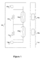
- the safety switch comprises a first part 10 and a second part 14.
- the first part 10 may be installed to the door part on the left side and the second part 14 on the right part so that these two parts are in close proximity of each other when the doors are closed. Close proximity does not mean a direct contact and will be explained later.
- the first part 10 comprises two resistors 11a and 11b, two magnetic switches 12a and 12b and connectors 13a and 13b for coupling to e.g. elevator safety circuit.
- the second part 14 comprises permanent magnets 15a and 15b. These permanent magnets 15a and 15b can also be separate pieces that are mounted to the door.
- Switches 12a are 12b are switches commonly called as reed switches.
- the switch opens and closes according to the magnetic field in the vicinity.
- the switches 12a and 12b are such that they are open in normal condition. When magnets, such as permanent magnets 15a and 15b arrive close enough, the switches will close.
- the circuit of figure 1 is such that when both of the switches are closed the electricity runs through switches. Switches are installed in series so that both switches have a parallel resistor 11a and 11b. If the switch is open the electricity runs through respective resistor. Thus, an open switch is bypassed by the resistor.
- the first part 10 comprises connectors 13a and 13b that may be used for measuring the resistance across the circuit. Based on the information received from the switch and from other systems it may be determined if the door is open for a purpose or because of a fault. For example, the first part 10 may be connected to a measurement device that provides the measurement result to a system controlling the door. Then, from the measurement results it can be determined if the door is open. Furthermore, the external system knows if the door should be open. For example, if the door has been just opened or a loading switch has been triggered and the door doesn't close, there is no need to react. However, if the system does not know any reason for the door being open, an alarm may be launched and sent to the maintenance person.
- an information message may be sent to a maintenance person.
- the maintenance person knows that the door is safe and operable when one of the switches is working and a maintenance visit can be scheduled when it is most convenient.
- a door comprising a switch according to the description above is used in an elevator car.
- the door is typically a sliding door such that the door has a left part and right part.
- the first part 10 of the switch may be attached to the left part and the second part of the switch 14 may be attached to the right part.
- the parts should be attached so that they meet when the doors are closed.
- the first part 10 and second part 14 may be arranged such that they do not have mechanical contact but are, for example, behind respective protective covers.
- the attachment must be such that magnets are powerful enough to close the switches 12a and 12b when operating normally. Thus, by providing powerful magnets the distance between the first part 10 and second part 14 may be longer.
- the safety switch may be installed to an elevator door or other elevator component that is connected to the elevator security circuit.
- This circuit is used for monitoring the safety of an elevator by detecting possible faults in the elevator. In case of fault the information derived from the safety circuit.
- the circuit may comprise a plurality of safety switches and/or sensors and is not limited to door security discussed above.
- the safety circuit typically comprises door safety switches.
- the safety switch described above is fully compatible with conventional safety circuits and replacing conventional safety switches by safety switches discussed above does not require any further modifications physical components. However, depending on the case, there may be a need for changing the controller software controlling the safety circuit.
- the safety switch described above is easy to manufacture in different shapes and sizes. Furthermore, it can be manufactured from a plurality of different materials. Thus, it is possible to manufacture safety switches that are fully compatible with the space and connector requirements of existing applications.
- the switch may be encapsulated in a protective material like resin or epoxy. These materials will provide very good protective properties and can easily be manufactured in different shapes and sizes.
- the safety switch does not need to be exactly of same shape because there is no need for mechanical connection. In other words, it is enough that the shape and size are compatible with the space to which the safety switch is installed.
Priority Applications (1)
| Application Number | Priority Date | Filing Date | Title |
|---|---|---|---|
| EP15175699.6A EP3116012A1 (de) | 2015-07-07 | 2015-07-07 | Schutzschalter |
Applications Claiming Priority (1)
| Application Number | Priority Date | Filing Date | Title |
|---|---|---|---|
| EP15175699.6A EP3116012A1 (de) | 2015-07-07 | 2015-07-07 | Schutzschalter |
Publications (1)
| Publication Number | Publication Date |
|---|---|
| EP3116012A1 true EP3116012A1 (de) | 2017-01-11 |
Family
ID=53673741
Family Applications (1)
| Application Number | Title | Priority Date | Filing Date |
|---|---|---|---|
| EP15175699.6A Withdrawn EP3116012A1 (de) | 2015-07-07 | 2015-07-07 | Schutzschalter |
Country Status (1)
| Country | Link |
|---|---|
| EP (1) | EP3116012A1 (de) |
Cited By (1)
| Publication number | Priority date | Publication date | Assignee | Title |
|---|---|---|---|---|
| DE102022124299A1 (de) | 2022-09-21 | 2024-03-21 | Ifm Electronic Gmbh | Berührungslos arbeitender Zweidraht Sicherheitssensor |
Citations (5)
| Publication number | Priority date | Publication date | Assignee | Title |
|---|---|---|---|---|
| DE20113027U1 (de) * | 2001-08-04 | 2001-11-22 | Pack Oliver | Schalter und Positionsdetektor |
| DE10138342A1 (de) * | 2001-07-27 | 2003-02-20 | Pilz Gmbh & Co | Vorrichtung zum Überwachen einer Schließposition zweier relativ zueinander beweglicher Teile, insbesondere zur Verwendung als berührungsloser Türkontaktschalter |
| US20060192676A1 (en) * | 2005-02-16 | 2006-08-31 | Vogt William R | Alarm sensor |
| DE202006001941U1 (de) * | 2006-02-06 | 2007-09-06 | Fraba Vitector Gmbh | Berührungsloser Sensor mit Sicherheitsfunktion |
| EP2722300A1 (de) * | 2007-01-03 | 2014-04-23 | Kone Corporation | Sicherheitsanordnung für einen Aufzug |
-
2015
- 2015-07-07 EP EP15175699.6A patent/EP3116012A1/de not_active Withdrawn
Patent Citations (5)
| Publication number | Priority date | Publication date | Assignee | Title |
|---|---|---|---|---|
| DE10138342A1 (de) * | 2001-07-27 | 2003-02-20 | Pilz Gmbh & Co | Vorrichtung zum Überwachen einer Schließposition zweier relativ zueinander beweglicher Teile, insbesondere zur Verwendung als berührungsloser Türkontaktschalter |
| DE20113027U1 (de) * | 2001-08-04 | 2001-11-22 | Pack Oliver | Schalter und Positionsdetektor |
| US20060192676A1 (en) * | 2005-02-16 | 2006-08-31 | Vogt William R | Alarm sensor |
| DE202006001941U1 (de) * | 2006-02-06 | 2007-09-06 | Fraba Vitector Gmbh | Berührungsloser Sensor mit Sicherheitsfunktion |
| EP2722300A1 (de) * | 2007-01-03 | 2014-04-23 | Kone Corporation | Sicherheitsanordnung für einen Aufzug |
Cited By (1)
| Publication number | Priority date | Publication date | Assignee | Title |
|---|---|---|---|---|
| DE102022124299A1 (de) | 2022-09-21 | 2024-03-21 | Ifm Electronic Gmbh | Berührungslos arbeitender Zweidraht Sicherheitssensor |
Similar Documents
| Publication | Publication Date | Title |
|---|---|---|
| JP6715576B2 (ja) | スイッチング装置 | |
| US8289026B2 (en) | Recording device for recording the switch state of an electromagnetic switch device | |
| US9455111B2 (en) | Method and structure for monitoring breaker status contacts on circuit breaker applications | |
| RU2701865C2 (ru) | Коммутационное устройство для корпусов, снабженных защитой от внешних воздействий | |
| CN106437304B (zh) | 安全系统 | |
| CN106486899A (zh) | 用于具有环境保护的壳体的开关设备 | |
| JP2015536006A (ja) | ロールシャッター用警報システム | |
| EP3116012A1 (de) | Schutzschalter | |
| CN106206116A (zh) | 高速闸刀开关 | |
| US8847580B1 (en) | Tamperproof magnetic proximity sensor | |
| JP5765840B2 (ja) | 引き違い窓の開窓検知装置 | |
| EP1880452B1 (de) | Einrichtung zur fernüberwachung des zustands mindestens eines einpol-überspannungsschutzes | |
| CN101834071B (zh) | 工业特种门专用安全监测智能开关 | |
| US20090194405A1 (en) | Safety Switch | |
| JP5156884B2 (ja) | 保安磁気センサ | |
| GB2450890A (en) | Magnetic contact | |
| CN105044594B (zh) | 用于检验开关自保持磁体的方法及执行该方法的检验装置 | |
| CN212105614U (zh) | 一种适用于常闭防火门的开关监控系统 | |
| EP2590197B1 (de) | Magnetsensor für Betrieb mit einem entsprechenden Magnet und magnetischen Kontakt umfassend den magnetischen Sensor und entsprechenden Magneten | |
| WO2018146674A1 (en) | Door\window opening detector | |
| US3902170A (en) | Fault indicator for electrical circuits | |
| KR20210079933A (ko) | 차량 및 차량용 인터락 모니터링 회로 | |
| US9305443B2 (en) | LED security sensor | |
| KR20020062092A (ko) | 엘리베이터 시스템의 도어상태 감시장치 및 그 방법과이를 이용하는 엘리베이터 제어기 | |
| AU2017251485B2 (en) | System for detecting an overload and electrical differential protection device for an electrical line |
Legal Events
| Date | Code | Title | Description |
|---|---|---|---|
| PUAI | Public reference made under article 153(3) epc to a published international application that has entered the european phase |
Free format text: ORIGINAL CODE: 0009012 |
|
| AK | Designated contracting states |
Kind code of ref document: A1 Designated state(s): AL AT BE BG CH CY CZ DE DK EE ES FI FR GB GR HR HU IE IS IT LI LT LU LV MC MK MT NL NO PL PT RO RS SE SI SK SM TR |
|
| AX | Request for extension of the european patent |
Extension state: BA ME |
|
| STAA | Information on the status of an ep patent application or granted ep patent |
Free format text: STATUS: THE APPLICATION IS DEEMED TO BE WITHDRAWN |
|
| 18D | Application deemed to be withdrawn |
Effective date: 20170712 |