EP3115981A1 - Disaster response system, disaster response method, disaster-sensing device, and processing method therefor - Google Patents
Disaster response system, disaster response method, disaster-sensing device, and processing method therefor Download PDFInfo
- Publication number
- EP3115981A1 EP3115981A1 EP15757900.4A EP15757900A EP3115981A1 EP 3115981 A1 EP3115981 A1 EP 3115981A1 EP 15757900 A EP15757900 A EP 15757900A EP 3115981 A1 EP3115981 A1 EP 3115981A1
- Authority
- EP
- European Patent Office
- Prior art keywords
- disaster
- prediction
- detection
- index data
- operation mode
- Prior art date
- Legal status (The legal status is an assumption and is not a legal conclusion. Google has not performed a legal analysis and makes no representation as to the accuracy of the status listed.)
- Withdrawn
Links
Images


Classifications
-
- G—PHYSICS
- G08—SIGNALLING
- G08B—SIGNALLING OR CALLING SYSTEMS; ORDER TELEGRAPHS; ALARM SYSTEMS
- G08B31/00—Predictive alarm systems characterised by extrapolation or other computation using updated historic data
-
- H—ELECTRICITY
- H04—ELECTRIC COMMUNICATION TECHNIQUE
- H04L—TRANSMISSION OF DIGITAL INFORMATION, e.g. TELEGRAPHIC COMMUNICATION
- H04L67/00—Network arrangements or protocols for supporting network services or applications
- H04L67/01—Protocols
- H04L67/12—Protocols specially adapted for proprietary or special-purpose networking environments, e.g. medical networks, sensor networks, networks in vehicles or remote metering networks
- H04L67/125—Protocols specially adapted for proprietary or special-purpose networking environments, e.g. medical networks, sensor networks, networks in vehicles or remote metering networks involving control of end-device applications over a network
-
- H—ELECTRICITY
- H04—ELECTRIC COMMUNICATION TECHNIQUE
- H04Q—SELECTING
- H04Q9/00—Arrangements in telecontrol or telemetry systems for selectively calling a substation from a main station, in which substation desired apparatus is selected for applying a control signal thereto or for obtaining measured values therefrom
-
- H—ELECTRICITY
- H04—ELECTRIC COMMUNICATION TECHNIQUE
- H04W—WIRELESS COMMUNICATION NETWORKS
- H04W4/00—Services specially adapted for wireless communication networks; Facilities therefor
- H04W4/30—Services specially adapted for particular environments, situations or purposes
- H04W4/38—Services specially adapted for particular environments, situations or purposes for collecting sensor information
-
- G—PHYSICS
- G08—SIGNALLING
- G08B—SIGNALLING OR CALLING SYSTEMS; ORDER TELEGRAPHS; ALARM SYSTEMS
- G08B21/00—Alarms responsive to a single specified undesired or abnormal condition and not otherwise provided for
- G08B21/02—Alarms for ensuring the safety of persons
- G08B21/10—Alarms for ensuring the safety of persons responsive to calamitous events, e.g. tornados or earthquakes
-
- H—ELECTRICITY
- H04—ELECTRIC COMMUNICATION TECHNIQUE
- H04Q—SELECTING
- H04Q2209/00—Arrangements in telecontrol or telemetry systems
- H04Q2209/40—Arrangements in telecontrol or telemetry systems using a wireless architecture
-
- H—ELECTRICITY
- H04—ELECTRIC COMMUNICATION TECHNIQUE
- H04W—WIRELESS COMMUNICATION NETWORKS
- H04W4/00—Services specially adapted for wireless communication networks; Facilities therefor
- H04W4/02—Services making use of location information
Definitions
- the present invention relates to a technology for predicting and detecting a disaster.
- a bridge monitoring system and the like which detect abnormalities of bridges, have been provided.
- meteorological observatories and prefectural governments issue landslide alert information based on a soil water index, a predicted accumulated precipitation amount per predetermined time, and the like.
- the soil water index is estimated using a method referred to as a tank model. Estimating a degree of risk of landslide based on a rainfall amount using a stability analysis method of a slope of semi-infinite length has also been carried out.
- a collapse monitoring system that detects deformation or collapse of slopes, such as a mountainous region and a cliff.
- a plurality of wireless communication terminals that have sensors for detecting abnormalities are placed on mountain slopes, and the wireless communication terminals perform multi-hop communication and deliver abnormality information detected by the respective sensors to a base station.
- a system that performs prediction of disaster occurrence, such as a cliff failure, a mudslide, and a landslide, and evacuation recommendation is proposed.
- fluctuation data detected by a plurality of sensors are collected by a detection relay device by means of RFID (Radio Frequency Identification) communication, transmitted from the detection relay device to a server by means of wireless communication, and analyzed.
- RFID Radio Frequency Identification
- the present invention is made in consideration of the above-described situation, and an object of the present invention is to provide a technology that enables enlarging the range and increasing the accuracy of detection and prediction of a disaster.
- a disaster response system relates the system including: a server device; a relay device that is communicable with the server device; and a plurality of disaster-sensing devices each of which is arranged at a predetermined position, the predetermined position being within a range wirelessly communicable with at least one of another disaster-sensing device and the relay device.
- Each of the disaster-sensing devices includes: a plurality of sensors each of which obtains one of a plurality of types of measurement data at an arrangement position in time series form; a detection processing unit that processes at least one of the plurality of types of measurement data obtained by at least one of the plurality of sensors and generating detection index data that serve as an index of disaster occurrence detection; a prediction processing unit that processes the plurality of types of measurement data obtained by the plurality of sensors in time series form and generates prediction index data that serve as an index of disaster occurrence prediction; and a wireless communication circuit that transmits a wireless signal indicating at least one of the detection index data generated by the detection processing unit and the prediction index data generated by the prediction processing unit, and the server device includes an information collection unit that receives, from the relay device, the detection index data at each arrangement position and the prediction index data at each arrangement position transmitted from each of the plurality of disaster-sensing devices.
- a disaster response method relates the disaster response method executed by a disaster response system including: a server device; a relay device that is communicable with the server device; and a plurality of disaster-sensing devices each of which is arranged at a predetermined position, the predetermined position being within a range wirelessly communicable with at least one of another disaster-sensing device and the relay device.
- the disaster response method includes: in each of the disaster-sensing devices: obtaining each one of a plurality of types of measurement data at an arrangement position in time series form; processing at least one type of measurement data among the plurality of types of measurement data obtained and generating detection index data that serve as an index of disaster occurrence detection; processing the plurality of types of measurement data obtained in time series form and generating prediction index data that serve as an index of disaster occurrence prediction; and transmitting a wireless signal indicating at least one of the detection index data and the prediction index data, and in the server device, receiving, from the relay device, the detection index data at each arrangement position and the prediction index data at each arrangement position transmitted from each of the plurality of disaster-sensing devices.
- a disaster-sensing device includes: a detection processing unit that processes at least one type of measurement data obtained by a plurality of sensors each of which obtains one of a plurality of types of measurement data at an arrangement position in time series and generating detection index data that serve as an index of disaster occurrence detection; and a prediction processing unit that processes the plurality of types of measurement data obtained by at least one of the plurality of sensors in time series and generating prediction index data that serve as an index of disaster occurrence prediction; and a wireless communication circuit that transmits a wireless signal indicating at least one of the detection index data generated by the detection processing unit and the prediction index data generated by the prediction processing unit.
- a processing method of a disaster-sensing device includes: obtaining a plurality of types of measurement data at an arrangement position in time series form; processing at least one type of measurement data among the plurality of types of measurement data obtained and generating detection index data that serve as an index of disaster occurrence detection; processing the plurality of types of measurement data obtained in time series form and generating prediction index data that serve as an index of disaster occurrence prediction; and transmitting a wireless signal indicating at least one of the detection index data and the prediction index data.
- the above-described respective aspects enable providing a technology that enables enlarging the range and increasing the accuracy of detection and prediction of a disaster.
- exemplary embodiments of the present invention will be described.
- a disaster response system and a disaster response method that perform prediction and detection of disasters are exemplified.
- the types of disasters to be dealt with in the respective exemplary embodiments below are not limited to specific ones.
- Fig. 1 is a diagram conceptually illustrating a configuration of a disaster response system 1 in a first exemplary embodiment.
- the disaster response system 1 is also referred to as a system 1 in an abbreviated manner.
- the system 1 includes a server device 30, a relay device 20, which is communicable with the server device 30, and a plurality of disaster-sensing devices 10.
- Each disaster-sensing device 10 is arranged at a predetermined position within a range wirelessly communicable with at least one of the other disaster-sensing devices 10.
- At least one of the plurality of disaster-sensing devices 10 is positioned within a range wirelessly communicable with the relay device 20.
- the plurality of disaster-sensing devices 10 are also referred to as the disaster-sensing devices 10 (#1) to (#n) to identify individual ones.
- the disaster-sensing devices 10 are referred to as sensing devices 10 in an abbreviated manner.
- the server device 30 is a so-called computer and includes, for example, a CPU (Central Processing Unit) 31, a memory 32, an input/output interface (I/F) 33, and a communication circuit 34, which are interconnected by a bus.
- a CPU Central Processing Unit
- memory 32 a RAM (Random Access Memory), a ROM (Read Only Memory), and a hard disk are applicable, but applicable components are not limited thereto.
- the communication circuit 34 performs communication with other computers and devices.
- a portable recording medium may be connected to the communication circuit 34.
- the input/output I/F 33 may be connected to a user interface device, such as a display device 35 and an input device 36.
- the display device 35 is a device, such as an LCD (Liquid Crystal Display) and a CRT (Cathode Ray Tube) display, that displays drawing data that are processed by the CPU 31 and/or a GPU (Graphics Processing Unit) (not illustrated).
- the input device 36 is a device, such as a keyboard and a mouse, that accepts user operation input.
- the display device 35 and the input device 36 may be combined into one body to be achieved as a touch panel.
- the relay device 20 includes a CPU 21, a memory 22, a communication circuit 24, a wireless communication circuit 25, and an antenna 26.
- the wireless communication circuit 25 is a hardware component that includes a wireless circuit and performs wireless communication with at least one of the sensing devices 10 (#1) to (#n) by way of the antenna 26.
- the communication circuit 24 is a hardware component that performs communication with the server device 30 by way of a communication network 5.
- the communication network 5 may be a wired or wireless public telecommunication network or a private telecommunication network, such as a disaster prevention wireless network.
- Each of the sensing devices 10 (#1) to (#n) includes an antenna 11, a plurality of sensors 12, a CPU 13, a memory 14, and a wireless communication circuit 15.
- the reference signs of the respective components of the sensing device 10 (#n) are omitted.
- Each of the plurality of sensors 12 obtains one of a plurality of types of measurement data at the arrangement position thereof in time series form.
- the plurality of measurement data to be obtained are not limited to specific types of data as long as being information, such as light, sound, vibration, rainfall amount, airflow volume, soil moisture content, temperature, humidity, quantity of sunlight, inclination, and pressure, that may possibly take different values at and before the occurrence of a disaster from values at normal times.
- the number of sensors 12 is not limited to a specific number in the same manner.
- the wireless communication circuit 15 is a hardware component that includes a wireless circuit and performs wireless communication with another sensing device or the relay device 20 by way of the antenna 11.
- the respective sensing devices 10 (#1) to (#n) may include the same configuration and are thus collectively referred to as the sensing devices 10 in the following description unless particularly required.
- the hardware configurations of the server device 30, the relay device 20, and the sensing devices 10 are not limited to a specific configuration.
- the numbers of server devices 30, relay devices 20, and sensing devices 10 included in the system 1 are also not limited to specific numbers.
- Fig. 2 is a diagram conceptually illustrating a processing configuration example of the disaster-sensing device 10 in the first exemplary embodiment.
- the sensing device 10 includes a detection processing section 51, a prediction processing section 52, and a wireless communication section 53.
- the detection processing section 51, the prediction processing section 52, and the wireless communication section 53 are achieved by means of, for example, the CPU 13 executing programs stored in the memory 14.
- Such programs are stored in a portable recording medium, such as a CD (Compact Disc) and a memory card, and the like.
- the detection processing section 51 processes at least one type of measurement data obtained by at least one of the plurality of sensors 12 and generates detection index data, which serve as an index of disaster occurrence detection.
- the detection index data are not measurement data themselves obtained by a sensor 12 but data into which the measurement data are processed.
- the detection index data may be any type of data as long as serving as an index of disaster occurrence detection.
- the detection index data may be data indicating a result detection of a disaster occurrence, as described later.
- the prediction processing section 52 processes the plurality of types of measurement data obtained by the plurality of sensors 12 in time series form and generates prediction index data, which serve as an index of disaster occurrence prediction.
- the prediction index data are not measurement data themselves obtained by the sensors 12 but data that are obtained by processing the measurement data.
- the prediction index data may be any type of data as long as serving as an index of disaster occurrence prediction.
- the prediction index data may be data indicating a degree of risk of disaster occurrence, as described later.
- the wireless communication section 53 makes the wireless communication circuit 15 transmit, from the antenna 11, a wireless signal indicating at least one of the detection index data generated by the detection processing section 51 and the prediction index data generated by the prediction processing section 52.
- the wireless signal transmitted from the antenna 11 includes, in addition to at least one of the detection index data and the prediction index data, identification information of each sensing device 10. Using the identification information, a sensing device 10 that is the transmission source of the detection index data or the prediction index data is recognized.
- the wireless communication section 53 may achieve the above-described processing by generating a bit string indicating the result of the detection and the prediction index data based on a predetermined signal format and passing the bit string to the wireless communication circuit 15.
- the wireless communication section 53 does not have to be included.
- the wireless communication section 53 may also make the wireless communication circuit 15 transmit a wireless signal indicating both the generated detection index data and the generated prediction index data.
- the wireless communication section 53 may also make the wireless communication circuit 15 transmit, in a wireless signal, representative data, among the generated detection index data, that satisfy a predetermined condition and make the wireless communication circuit 15 transmit, in a wireless signal, representative data, among the generated prediction index data, that satisfy a predetermined condition.
- Fig. 3 is a diagram conceptually illustrating a processing configuration example of the server device 30 in the first exemplary embodiment.
- the server device 30 includes an information collection section 61.
- the information collection section 61 is achieved by means of, for example, the CPU 31 executing a program stored in the memory 32.
- a program is installed from a portable recording medium, such as a CD and a memory card, or another computer on the network by way of the input/output I/F 33 and stored in the memory 32.
- the information collection section 61 receives detection index data at the arrangement position and prediction index data at the arrangement position of each sensing device 10, which are transmitted by each sensing device 10, from the relay device 20.
- Fig. 4 is a sequence chart illustrating an operation example of the system 1 in the first exemplary embodiment.
- the execution subject may be at least one device that composes the system 1.
- Each sensing device 10 obtains each one of a plurality of types of measurement data at the arrangement position thereof in time series form (S41), and processes at least one type of measurement data among the plurality of types of measurement data obtained.
- Each sensing device 10 generates detection index data, which serve as an index of disaster occurrence detection (S42), processes the plurality of types of measurement data, which have been obtained in time series form, and generates prediction index data, which serve as an index of disaster occurrence prediction (S43). Subsequently, each sensing device 10 transmits a wireless signal that indicates at least one of the generated detection index data and the generated prediction index data (S44).
- the server device 30 receives the detection index data at each arrangement position and the prediction index data at each arrangement position, which have been transmitted by each sensing device 10, from the relay device 20 (S46).
- the plurality of sensing devices 10 each of which has a plurality of sensors that are capable of obtaining a plurality of types of measurement data are arranged at predetermined positions individually, and, at each arrangement position, each of the plurality of types of measurement data are obtained successively.
- detection index data which serve as an index of disaster occurrence detection
- prediction index data which serve as an index of disaster occurrence prediction
- a wireless signal indicating at least one of the detection index data and the prediction index data is transmitted from each sensing device 10.
- the detection index data at each arrangement position and the prediction index data at each arrangement position, which are transmitted in this way, are received by the server device 30 by way of the relay device 20.
- index data on detection and prediction of disaster occurrence are generated based on at least one type of measurement data obtained at the arrangement position of each sensing device 10. Therefore, detection index data and prediction index data that reflect characteristics at each position (positional condition) can be generated. According to the first exemplary embodiment, performing detection and prediction of disaster occurrence using the detection index data and the prediction index data enables the accuracy of the detection and prediction to be improved, compared with a method that does not take into account any positional condition (soil condition and the like).
- index data on detection and prediction of disaster occurrence are generated with respect to each sensing device 10, that is, at each different position, prediction index data and detection index data of disaster occurrence with respect to a plurality of positions can be collected in the server device 30.
- detection index data and prediction index data that are obtained through processing of measurement data instead of measurement data themselves, are collected in the server device 30, a load on detection processing and prediction processing of disaster occurrence performed in the server device 30 can be reduced.
- the plurality of sensing devices 10 may be arranged at desired positions.
- a system installation (initial operation) cost can be reduced, which enables the extent of installation of the system 1 to be enlarged easily.
- each sensing device 10 performs wireless communication with at least one of the other sensing devices 10.
- Each sensing device 10 performs wireless communication with the relay device 20 directly or by way of another sensing device 10 depending on the arrangement position of the sensing device 10.
- Detection index data and prediction index data obtained by each sensing device 10 are delivered to the server device 30 by way of the relay device 20. Since the first exemplary embodiment does not thus require connections by wired communication lines and the like between the sensing devices 10 and between the sensing devices 10 and the relay device 20, a system installation cost can be reduced.
- each sensing device 10 transmits detection index data and prediction index data, transmitting a plurality of types of measurement data themselves successively is not always required.
- transmitting measurement data themselves successively enables the volume of communication transmitted from the sensing device 10 to be reduced, which enables electric power consumption required for wireless communication performed by the respective sensing devices 10 and the relay device 20 to be reduced.
- the volume of communication between the relay device 20 and the server device 30 can also be reduced.
- a disaster response system 1 in the second exemplary embodiment will be described with a focus on different features from the first exemplary embodiment.
- a description of the same features as those of the first exemplary embodiment will be omitted appropriately.
- a system configuration and a hardware configuration of the system 1 in the second exemplary embodiment are the same as the first exemplary embodiment.
- each sensing device 10 in the second exemplary embodiment is capable of operating for a long time due to power saving control, which will be described later, even when using a primary battery or a secondary battery as a main power source, and, thus, wiring with a commercial power source can be eliminated.
- a plurality of sensing devices 10 included in the system 1 in the second exemplary embodiment form at least one multi-hop wireless network.
- the number and arrangement of relay devices 20 are determined.
- a wireless communication circuit 15 of a sensing device 10 that serves as a relay station wirelessly relays detection index data and prediction index data wirelessly transmitted from another disaster-sensing device 10 to the relay device 20 or still another disaster-sensing device 10 (a sensing device 10 at a higher level).
- the relay processing may be achieved by the wireless communication circuit 15 or by means of collaboration between the wireless communication circuit 15 and a wireless communication section 53.
- the wireless communication circuit 15 and the wireless communication section 53 may demodulate and modulate a signal received from another disaster-sensing device 10 and generate a new signal or relay the signal without performing demodulation and modulation.
- Fig. 5 is a diagram conceptually illustrating a processing configuration example of the sensing device 10 in the second exemplary embodiment. As illustrated in Fig. 5 , the sensing device 10 in the second exemplary embodiment further includes a model generation section 55, an operation control section 56, and a time correction section 57, in addition to the configuration of the first exemplary embodiment.
- the model generation section 55, the operation control section 56, and the time correction section 57 are also achieved by means of a CPU (not illustrated) executing programs stored in a memory (not illustrated).
- the model generation section 55 generates a relationship model on a plurality of types of measurement data based on the plurality of types of measurement data obtained by a plurality of sensors 12 in time series form. For example, the model generation section 55 may generate, as the above-described relationship model, a regression equation that has one of the plurality of types of measurement data as a criterion variable and the other types of measurement data as explanatory variables. A plurality of relationship models may be generated. In this case, the model generation section 55 may generate a plurality of regression equations that have one of the plurality of types of measurement data as a criterion variable and each of which has one out of the other types of measurement data as an explanatory variable. Any known method can be used for the generation of the relationship model.
- the model generation section 55 may use, as a variable in the relationship model, frequency time series data, which are obtained by applying frequency transformation to the temporal waveform data and sorting feature amounts of frequency component data obtained from the transformation in time series form.
- the model generation section 55 may also calculate a natural frequency (also referred to as a dominant frequency) of soil in a predetermined region based on the temporal waveform data and use the natural frequency as a variable in the relationship model.
- a natural frequency also referred to as a dominant frequency
- the prediction processing section 52 processes the plurality of types of measurement data obtained by the plurality of sensors 12 using the relationship model generated by the model generation section 55 and generates prediction index data.
- the relationship model generated by the model generation section 55 represents correlations among the plurality of types of measurement data, which were obtained at normal times when no disaster had occurred.
- the prediction processing section 52 generates prediction index data of disaster occurrence in accordance with fluctuations in the correlations that the relationship model represents. For example, the prediction processing section 52 may substitute latest measurement data obtained by the sensors 12 into the relationship model to calculate at least one piece of prediction data and determine a difference between the piece of prediction data and the latest measurement data obtained by a sensor 12 to be prediction index data.
- the wireless communication section 53 extracts instructions individually from a plurality of instruction signals from the server device 30, which have been received successively by the wireless communication circuit 15. The instructions are used by the operation control section 56, which will be described later.
- the wireless communication section 53 further receives common time information.
- the wireless communication circuit 15 includes a GPS (Global Positioning System) receiver and time information received by the GPS receiver is received by the wireless communication section 53 as the common time information.
- GPS Global Positioning System
- the common time information may, however, be received from the server device 30 by means of a wireless signal.
- the received common time information is used by the time correction section 57, which will be described later.
- the operation control section 56 performs power saving control.
- the operation of hardware components such as the sensor 12, the CPU 13, and the wireless communication circuit 15, consumes electric power.
- the respective hardware components are required to be operated.
- the exemplary embodiment provides each sensing device 10 with a plurality of operation modes and switches the plurality of operation modes appropriately to achieve power saving.
- the operation control section 56 switches a plurality of operation modes including a first operation mode, a second operation mode, and a third operation mode, based on the plurality of instruction signals received by the wireless communication section 53.
- switching operation modes means to control the operations of hardware components and software components included in a sensing device 10 so that the hardware components and software components are brought into a state in which an operation mode after switching is operated.
- the first operation mode is an operation mode in which the plurality of sensors 12 are put in an inoperable state and the wireless communication circuit 15 is switched between an operable state and an inoperable state cyclically.
- the second operation mode is an operation mode in which the plurality of sensors 12 are put in the inoperable state and the wireless communication circuit 15 is put in a continuously operable state.
- the third operation mode is an operation mode in which the plurality of sensors 12 and the wireless communication circuit 15 are put in operable states.
- the wireless communication circuit 15 being in the operable state means being in a state in which the wireless communication circuit 15 is able to receive or transmit a wireless signal.
- the wireless communication circuit 15 being in the inoperable state means being in a state in which the wireless communication circuit 15 is neither able to receive nor transmit a wireless signal.
- the sensor 12 being in the operable state means being in a state in which the sensor 12 is able to obtain measurement data
- the sensor 12 being in the inoperable state means being in a state in which the sensor 12 is unable to obtain measurement data.
- power supply thereto may be shut off completely or smaller power than when in the operable states may be supplied.
- the plurality of operation modes to be switched may be three operation modes, namely the first operation mode, the second operation mode, and the third operation mode, or four or more operation modes including another operation mode.
- an operation mode in which the largest power is consumed is the third operation mode
- an operation mode except the third operation mode in which the largest power is consumed is the second operation mode
- an operation mode in which the least power is consumed is the first operation mode.
- shortening a time during which the wireless communication circuit 15 is in the operable state and lengthening a time during which the wireless communication circuit 15 is in the inoperable state enable the power consumption to be further reduced.
- the wireless communication circuit 15 is put in the operable state for 30 seconds every 10 minutes, and, in other times, put in the inoperable state.
- the respective times, in the first operation mode as described above, during which the wireless communication circuit 15 is in the inoperable state and in the operable state are determined in advance in accordance with characteristics and the like of a target disaster.
- the plurality of sensors 12 are put in the inoperable state and, thus, the detection processing section 51, the prediction processing section 52, and the model generation section 55 do not perform processing. Therefore, in the first and second operation modes, power consumption by the CPU 13 can also be reduced.
- the operation control section 56 is also capable of performing control that puts a priority on either power saving or the relationship model. For example, the operation control section 56 performs control so that the operation time in the first operation mode, of the plurality of operation modes, becomes longest. Since such control causes the time during which each sensing device 10 operates in the first operation mode, in which the least power is consumed, to become longest, power consumption by each sensing device 10 can be reduced. However, to increase the accuracy of the relationship model generated by the model generation section 55, the operation control section 56 may perform control in such a way as to force a sensing device 10 to be operated in the third operation mode for a predetermined period after the sensing device 10 is installed (a predetermined period after being activated), regardless of instruction signals.
- the operation control section 56 may also cause the third operation mode to transition to the first operation mode in a forcible manner based on the evaluation of the accuracy of the relationship model.
- the accuracy of the relationship model can be evaluated based on, for example, a difference between prediction data calculated using the relationship model and measurement data.
- the operation control section 56 may also perform alive monitoring of the sensors 12 in the first and second operation modes, in which the sensors 12 are put in the inoperable state. Such a configuration enables prevention of such a situation that the sensors 12 cannot be brought into the operable state due to a malfunction therein when it becomes required to bring the sensors 12 into the operable state.
- the first operation mode is not an operation mode in which the wireless communication circuit 15 is in the continuously operable state. That is, each sensing device 10 is not in a state of being continuously able to receive an instruction signal from the server device 30.
- the server device 30 may transmit instruction signals for the switch in a repetitive manner until the sensing device 10 has received the signals.
- this method is not preferable because the method causes useless instruction signals to be transmitted.
- the server device 30 grasp a period of time for which the wireless communication circuit 15 of each sensing device 10 operating in the first operation mode is put in the operable state and transmit the instruction signal in the grasped period of time.
- the respective sensing devices 10 and the server device 30 share common time.
- the time correction section 57 corrects the time of an internal clock based on common time information received by the wireless communication section 53. In particular, when operating in the first operation mode, the time correction section 57 corrects the time of the internal clock based on common time information received by the wireless communication circuit 15 (or the wireless communication section 53), which is brought into the operable state cyclically.
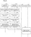
- Fig. 6 is a diagram conceptually illustrating a processing configuration example of the server device 30 in the second exemplary embodiment.
- the server device 30 in the second exemplary embodiment further includes an instruction section 63 in addition to the configuration of the first exemplary embodiment.
- the instruction section 63 is achieved by means of a CPU (not illustrated) executing a program stored in a memory (not illustrated).
- the instruction section 63 causes a plurality of instruction signals to be wirelessly transmitted successively to the plurality of sensing devices 10 by way of the relay device 20 in such a way that the operation time during which each sensing device 10 operates in the first operation mode, of the plurality of operation modes, becomes longest.
- the plurality of instruction signals include an instruction signal for switching from the first operation mode to the second operation mode, an instruction signal for switching from the second operation mode to the third operation mode, and an instruction signal for switching from the third operation mode to the first operation mode.
- the instruction section 63 may, by transmitting instruction data to the relay device 20, make the relay device 20 wirelessly transmit an instruction signal corresponding to the instruction data.
- the instruction section 63 transmits an instruction signal for causing the first operation mode to be switched to another operation mode among the plurality of instruction signals
- the instruction section 63 transmits the instruction signal by matching the timing of the transmission with the timing when the wireless communication circuit 15 of each sensing device 10 operating in the first operation mode is brought into the operable state cyclically.
- the transmission timing may be determined based on the time of the internal clock of the server device 30 or determined using a dedicated timer, which has been activated separately.
- the instruction section 63 may perform transmission control of instruction signals so that each sensing device 10 operates in the third operation mode for a predetermined period after the sensing device 10 is installed to increase the accuracy of the relationship model generated by the model generation section 55.
- Fig. 7 is a sequence chart illustrating an operation example of the system 1 in the second exemplary embodiment.
- the execution subject may be at least one device that composes the system 1.
- the same signs as in Fig. 4 are assigned to the steps in which the same processing as those of the first exemplary embodiment is performed.
- Each sensing device 10 is operating in the first operation mode (S71).
- the first operation mode the plurality of sensors 12 are put in the inoperable state, and the wireless communication circuit 15 is switched between the operable state and the inoperable state cyclically. Further, since the plurality of sensors 12 being in the inoperable state causes measurement data not to be obtained, generation processing of detection index data, generation processing of prediction index data, and update processing of the relationship model are not performed and, thus, a load on the CPU 13 is low. At this time, it is preferable that each sensing device 10 perform the alive monitoring of each of the sensors 12.
- the server device 30 makes the relay device 20 wirelessly transmit an instruction signal for causing each sensing device 10 to transition to the second operation mode (S72).
- the transmission timing of the instruction signal is matched with timing when the wireless communication circuit 15 of each sensing device 10 is in the operable state that occurs cyclically.
- each sensing device 10 When each sensing device 10 has received the instruction signal at a timing when the wireless communication circuit 15 is in the operable state, the sensing device 10 transitions from the first operation mode to the second operation mode (S73). Specifically, each sensing device 10 brings the wireless communication circuit 15 into the continuously operable state. At this time, the respective sensors 12 are kept in the inoperable state. This processing causes each sensing device 10 to become ready for receiving an instruction signal at any time. It is preferable that each sensing device 10 also perform the alive monitoring of each of the sensors 12 when the sensing device 10 is operating in the second operation mode.
- the server device 30 makes the relay device 20 wirelessly transmit an instruction signal for causing each sensing device 10 to transition to the third operation mode (S74).
- the transmission timing of the instruction signal may be set to any timing.
- each sensing device 10 transitions from the second operation mode to the third operation mode (S75). Specifically, each sensing device 10 brings each sensor 12 into the operable state. This processing causes the wireless communication circuit 15 and each sensor 12 to be brought into the operable states, and each sensing device 10 performs steps S41 to S44, as described in the first exemplary embodiment. At this time, each sensing device 10 may also update the relationship model based on the plurality of types of measurement data, which are obtained in time series form in step S41 (S78). The execution timing of the update of the relationship model (S78) may, however, be set to an arbitrarily timing as long as when no disaster occurrence has been detected and step S41 is being performed. When the accuracy of the relationship model is determined to be high, the update of the relationship model does not have to be performed.
- the server device 30 performs step S46 as described in the first exemplary embodiment.
- the server device 30 makes the relay device 20 wirelessly transmit an instruction signal to cause transition from the third operation mode to the first operation mode (not illustrated).
- Each sensing device 10 corrects the time of the internal clock, at any timing, based on the common time information received by the wireless communication circuit 15, which is in the operable state (not illustrated).
- a plurality of operation modes including the first operation mode, the second operation mode, and the third operation mode are provided to each sensing device 10, and the operation mode is switched so that each sensing device 10 operates in the first operation mode, in which power consumption is lowest, for the longest time.
- the wireless communication circuit 15 is halted cyclically, and the generation processing of detection index data and the generation processing of prediction index data are not performed, only a little power is consumed.
- the second exemplary embodiment enables each sensing device 10 to operate for a long time even when the sensing device 10 uses a primary battery or a secondary battery as the main power source and thus enables wiring with a commercial power source to be eliminated. Accordingly, the second exemplary embodiment enables an installation cost and operation cost for the system 1 to be reduced.
- the plurality of operation modes that are provided to each sensing device 10 as described above have different technological significance from operation modes provided to general devices and the like for power saving purpose.
- the technological significance of the plurality of operation modes and switching processing among the operation modes will be described.
- the present inventors have focused on existence of disasters, occurrence factors of which are limited. For example, a large portion of natural disasters occur caused by specific natural phenomena. Among other disasters, there are also disasters that occur caused by specific natural phenomena and specific events.
- the sensing device 10 that detects and predicts occurrences of such disasters is not required to be operated at a constant cycle, such as once every day and once every several hours, and may be operated in a concentrated manner when the specific natural phenomena or events are occurring.
- the present inventors have obtained an idea that configuring operation in the third operation mode, in which index data of the detection and prediction of disaster occurrence are generated, to be performed in limited periods of time and operation in another operation mode, in which minimal processing is available, to be performed in the other periods enables the power consumption of each sensing device 10 to be reduced. Further, the present inventors have found the first operation mode as described above as an operation mode, other than the third operation mode, to suppress power consumption at a sensing device 10 to a required minimum. However, in the first operation mode, since time intervals for which instruction signals can be received are limited, there is a possibility that transition to the third operation mode is delayed, resulting in delaying the detection and prediction of disaster occurrence.
- the present inventors have found the second operation mode as described above that, as an operation mode in which operation is performed between operation in the first operation mode and operation in the third operation mode, enables a fast transition to the third operation mode.
- Using the first operation mode in normal times causes operation in the first operation mode, in which power consumption is lowest, to be performed for the longest time, which results in enabling power consumption at each sensing device 10 to be reduced.
- transitioning the operation mode from the first operation mode to the second operation mode to, finally, the third operation mode as the probability of disaster occurrence increases enables the detection and prediction of disaster occurrence to be performed accurately and speedily.
- the plurality of sensing devices 10 included in the system 1 form at least one multi-hop wireless network.
- detection index data and prediction index data transmitted from a sensing device 10 may be delivered to the relay device 20 by way of other sensing devices 10. Therefore, the second exemplary embodiment enables the number of relay devices 20 in the system 1 to be reduced.
- a relationship model on a plurality of types of measurement data is generated in each sensing device 10, and prediction index data is generated in accordance with the relationship model. Since the relationship model is a model that represents relations among the plurality of types of measurement data based on measurement data obtained at the arrangement position of each sensing device 10, it is possible to generate highly accurate prediction index data at each arrangement position.
- Each sensing device 10 is arranged in a scattered manner at a wirelessly communicable distance with another sensing device 10 or a relay device 20.
- each sensing device 10 is arranged at a hardly visible position, such as under the ground and in a shadow.
- at least a portion of a sensing device 10 is sometimes buried in the ground.
- each sensing device 10 is buried in such a way that only portions of an antenna 11 and sensors 12 are exposed above the ground and the other portions are placed in the ground.
- the whole of a sensing device 10 is completely buried under the ground.
- at least a portion of a sensing device 10 is contained in a box.
- a sensing device 10 being buried under the ground or contained in a box enables the sensing device 10 to be easily protected against influence from phenomena in the outside world, such as wind, snow, rain, thunder, and heat.
- each sensing device 10 uses a primary battery or a secondary battery as a main power source as described in the second exemplary embodiment, it becomes required to replace or charge those batteries.
- the sensing devices 10 are arranged in a large area or at hardly visible positions, it is difficult for workers to grasp the positions of the sensing devices 10 in carrying out such maintenance work.
- a disaster response system 1 in the third exemplary embodiment will be described with a focus on different features from the first and second exemplary embodiments.
- a description of the same features as those of the first and second exemplary embodiments will be omitted appropriately.
- Fig. 8 is a diagram conceptually illustrating a processing configuration example of the sensing device 10 in the third exemplary embodiment. As illustrated in Fig. 8 , each sensing device 10 in the third exemplary embodiment further includes a holding section 58 in addition to the configuration of the second exemplary embodiment.
- the holding section 58 is achieved by means of a CPU (not illustrated) executing a program stored in a memory (not illustrated).
- the holding section 58 holds a sensing device's 10 own position information.
- a wireless communication circuit 15 has a GPS (Global Positioning System) receiver, and position information received by the GPS receiver is held in the holding section 58 as the above-described position information.
- GPS Global Positioning System
- the position information may, however, be manually set when the sensing device 10 is installed.
- a wireless communication section 53 transmits a wireless signal indicating the sensing device's 10 own position information, which is held in the holding section 58, in collaboration with the wireless communication circuit 15.
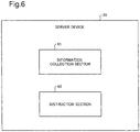
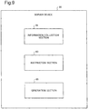
- Fig. 9 is a diagram conceptually illustrating a processing configuration example of a server device 30 in the third exemplary embodiment.
- the server device 30 in the third exemplary embodiment further includes a generation section 65 in addition to the configuration of the second exemplary embodiment.
- the generation section 65 is achieved by means of a CPU (not illustrated) executing a program stored in a memory (not illustrated).
- An information collection section 61 further receives position information of each of a plurality of sensing devices 10, which has been transmitted from the sensing device 10, from the relay device 20.
- the generation section 65 generates pieces of screen data that individually represent the positions of the respective sensing devices 10 using the position information of the sensing devices 10 received by the information collection section 61. Based on the screen data generated by the generation section 65, a screen individually showing the positions of the respective sensing devices 10 is displayed on a display device 35.
- the screen data can be printed by a printing device (not illustrated) as images that individually show the positions of the respective sensing devices 10.
- the screen data may also be provided to a client terminal that can access the server device 30.
- a maintenance worker accesses the server device 30 with a mobile terminal to display the screen on the mobile terminal.
- This configuration enables the maintenance worker to grasp the position of each sensing device 10 easily while comparing the position of the mobile terminal itself with the position of the sensing device 10.
- a disaster response method in the third exemplary embodiment, as described above, further includes a step of the respective sensing devices 10 wirelessly transmitting position information and a step of the server device 30 receiving the position information of the respective sensing devices 10 and generating screen data that individually show the positions of the respective sensing devices 10. These steps can be performed at any timing in an asynchronous manner from the respective steps in the above-described first and second exemplary embodiments.
- each sensing device 10 holds the position information of its own, and the position information of the sensing device 10 is wirelessly transmitted.
- pieces of screen data each of which represents the position of each sensing device 10 are generated based on the received position information. Therefore, according to the third exemplary embodiment, even when the respective sensing devices 10 are installed at hardly visible positions in a large area, a maintenance worker, referring to an output based on the screen data, is able to grasp the positions of the respective sensing devices 10 easily.
- a relay device 20 relays information transmitted from a server device 30 to respective sensing devices 10 and relays information transmitted from the respective sensing devices 10 to the server device 30. Details of such relaying processing is not particularly limited. For example, when receiving a wireless signal from each sensing device 10, the relay device 20 demodulates the received signal to extract individual information (detection index data and prediction index data, position information, and the like), which has been transmitted from the sensing device 10, together with the identification information of the sensing device 10, which is a transmission source. The relay device 20 transmits the extracted individual information and identification information to the server device 30.
- individual information detection index data and prediction index data, position information, and the like
- the relay device 20 holds the individual information and the identification information in association with each other, and, in response to a request from the server device 30, transmits the held individual information and identification information to the server device 30.
- the relay device 20 may also transmits the extracted individual information and identification information to the server device 30 autonomously without holding such information.
- the relay device 20 transmits a wireless signal corresponding to the information so that each sensing device 10 receives the signal.
- the relay device 20 may transmit a multicast wireless signal.
- the relay device 20 transmits a wireless signal addressed to a target sensing device 10, and the target sensing device 10 relays the wireless signal to lower-level nodes. Relaying processing by the relay device 20 is not limited to only such processing.
- the server device 30 may be configured to make a final decision on prediction and detection of disaster occurrence using detection index data and prediction index data collected by an information collection section 61 from the respective sensing devices 10.
- a detection processing section 51 may be configured to detect a disaster occurrence based on data that are obtained by processing at least one type of measurement data. For example, the detection processing section 51 is able to detect a disaster occurrence by holding a predetermined threshold value for disaster occurrence detection and comparing the data with the predetermined threshold value. In this case, the detection processing section 51 is able to generate detection index data that indicates the result of the detection. Further, the detection processing section 51 may generate a result of a detection and data that have served as evidence of the detection as detection index data.
- a prediction processing section 52 may be configured to determine a degree of risk of disaster occurrence based on data that are obtained by processing a plurality of types of measurement data. For example, the prediction processing section 52 is able to determine a degree of risk of disaster occurrence by holding a predetermined threshold value for measuring signs of disaster occurrence and comparing the data with the predetermined threshold value. The degree of risk may be indicated by a binary value of whether or not being in danger or a ternary or greater value representing a degree of danger. In this case, the prediction processing section 52 is capable of generating prediction index data that indicates the degree of risk. The prediction processing section 52 may generate a degree of risk and data that have served as evidence in determining the degree of risk as prediction index data.
- the detection processing section 51 may detect a disaster occurrence using not only measurement data obtained by sensors 12 of a sensing device 10 that includes the detection processing section 51 but also measurement data or detection index data obtained from another sensing device 10.
- all the sensing devices 10 may be categorized into either a device(s) that perform(s) the detection of disaster occurrence or a device(s) that do(es) not.
- the prediction processing section 52 determines a degree of risk of disaster occurrence
- measurement data obtained by sensors 12 of a sensing device 10 that includes the prediction processing section 52 are not the only data that the prediction processing section 52 may use.
- the prediction processing section 52 may also determine a degree of risk of disaster occurrence using measurement data or prediction index data transmitted from another sensing device 10.
- all the sensing devices 10 may be categorized into either a device(s) that determine(s) a degree of risk of disaster occurrence or a device(s) that do(es) not.
- the instruction section 63 of the server device 30 may perform transmission of a plurality of instruction signals for causing the operation mode of each sensing device 10 to be transitioned in the following manner.
- Fig. 10 is a diagram conceptually illustrating a processing configuration example of the server device 30. As illustrated in Fig. 10 , the server device 30 further includes an information obtaining section 67.
- the information obtaining section 67 is also achieved by means of a CPU (not illustrated) executing a program stored in a memory (not illustrated).
- the information obtaining section 67 obtains two predetermined types of issuance information among weather warning issuance information and disaster alert issuance information, which are transmitted from public institutions, and two predetermined types of cancellation information among weather warning cancellation information and disaster alert cancellation information, which are transmitted from the public institution.
- the weather warning issuance information is exemplified by warnings, advisories, and emergency warnings that are issued by meteorological observatories and local public bodies.
- the warnings include a heavy rain warning, a flood warning, a heavy snow warning, a storm warning, and the like
- the advisories include a heavy rain advisory, a gale advisory, a high-waves advisory, and the like.
- the disaster alert issuance information includes landslide alert information.
- the weather warning cancellation information and the disaster alert cancellation information include cancellation information corresponding to the above-described issuance information.
- the instruction section 63 Upon obtaining the above-described respective issuance information and the above-described respective cancellation information, the instruction section 63 causes the relay device 20 to wirelessly transmit a first instruction signal and a second instruction signal corresponding to the issuance information and a third instruction signal corresponding to the cancellation information to each sensing device 10 successively. It is preferable that transmission of the second instruction signal be made when issuance information having a higher degree of risk than that of the first instruction signal is obtained. It is preferable that transmission of the third instruction signal be made when cancellation information corresponding to all issuance information that was used for transmission determination of the first instruction signal and the second instruction signal is obtained.
- the operation control section 56 of each sensing device 10 upon receiving the first instruction signal, switches the operation mode from the first operation mode to the second operation mode, upon receiving the second instruction signal, switches the operation mode from the second operation mode to the third operation mode, and, upon receiving the third instruction signal, switches the operation mode from the third operation mode to the first operation mode.
- weather information and disaster information which are transmitted from responsible public institutions, are used as a determination condition of whether to transmit an instruction signal for each sensing device 10 to transition to an operation mode.
- This configuration enables detection index data and prediction index data to be surely generated when needed, which eventually enables detection and prediction of disaster occurrence to be made.
- Specific examples of the disaster that is targeted by the above-described system 1 include a landslide disaster.
- the plurality of sensors 12 of each sensing device 10 obtain at least one of a rainfall amount and a soil moisture content and vibration data as the above-described plurality of types of measurement data.
- the detection processing section 51 applies frequency analysis to vibration data obtained by one of the plurality of sensors 12 and, based on component data (power) in a predetermined frequency band obtained by the frequency analysis, generates detection index data.
- the prediction processing section 52 applies frequency analysis to the vibration data and, based on frequency component data obtained by the frequency analysis and at least one of the rainfall amount and the soil moisture content, generates prediction index data.
- the detection processing section 51 performs frequency transformation on the obtained vibration data and holds the transformed component data in the specific frequency band successively.
- the successively-held component data in the specific frequency band may be treated as detection index data.
- the detection processing section 51 may also hold only component data that indicates the largest power as detection index data.
- the detection processing section 51 may detect that a landslide disaster has occurred depending on whether the calculated power in the specific frequency band surpasses a predetermined level. In this case, the detection processing section 51 may treat the result of the detection as detection index data.
- the prediction processing section 52 may calculate, as prediction index data, data indicating a degree of breakdown in the correlation between the natural frequency of soil, obtained from vibration data, and the soil moisture content and the correlation between the natural frequency of soil and the rainfall amount.
- the prediction processing section 52 may also calculate a degree of excess over a predetermined threshold value at the degree of breakdown and consider the degree of excess as a degree of risk of disaster occurrence. In this case, the prediction processing section 52 may treat the degree of risk as prediction index data.
- each sensing device 10 for example, triggered by issuance of a heavy rain warning, issuance of a landslide alert information, cancellation of the heavy rain warning, or cancellation of the landslide alert information, which are announced by meteorological observatories and local public bodies, the operation mode of each sensing device 10 is switched.
- Fig. 11 is a diagram conceptually illustrating a specific example of transitions among operation modes.
- a sensing device 10 when neither heavy rain warning nor landslide alert information has been issued, a sensing device 10 operates in the first operation mode.
- the sensing device 10 transitions from the first operation mode to the second operation mode.
- the sensing device 10 transitions from the second operation mode to the third operation mode.
- the sensing device 10 transitions from the third operation mode to the first operation mode.
- the sensing device 10 When the heavy rain warning is cancelled without issuance of a landslide alert information after issuance of the heavy rain warning, the sensing device 10 is caused to transition from the second operation mode to the first operation mode. In a similar manner, when only the landslide alert information is cancelled after issuance of the heavy rain warning and the landslide alert information, the sensing device 10 transitions from the third operation mode to the second operation mode.
- a disaster response system including:
- each of the disaster-sensing devices further includes
- server device further includes
- each of the disaster-sensing devices further includes
- the disaster response system according to any one of supplemental notes 1 to 4, wherein the wireless communication circuit of at least one disaster-sensing device among the plurality of disaster-sensing devices wirelessly relays the detection index data and the detection index data wirelessly transmitted from another disaster-sensing device to the relay device or still another disaster-sensing device.
- each of the plurality of disaster-sensing devices further includes
- each of the disaster-sensing devices further includes
- the disaster response system according to any one of supplemental notes 1 to 7, wherein the plurality of sensors of each of the disaster-sensing devices obtain at least one of rainfall amount data and soil moisture content data and vibration data as the plurality of types of measurement data, the detection processing unit of each of the disaster-sensing devices applies frequency analysis to the vibration data obtained by one of the plurality of sensors and, based on component data in a predetermined frequency band obtained through the frequency analysis, generates the detection index data, and the prediction processing unit of each of the disaster-sensing devices applies frequency analysis to the vibration data obtained by one of the plurality of sensors and, based on frequency component data obtained through the frequency analysis and at least one of the soil moisture content data and the rainfall amount data obtained by another sensor, generates the prediction index data.
- the disaster response system according to any one of supplemental notes 1 to 8, wherein the detection processing unit detects a disaster occurrence based on data obtained through processing of the at least one of the plurality of types of measurement data and generates the detection index data indicating a result of the detection.
- the disaster response system according to any one of supplemental notes 1 to 9, wherein the prediction processing unit determines a degree of risk of disaster occurrence based on data obtained through processing of the plurality of types of measurement data and generates the prediction index data indicating the degree of risk.
- a disaster-sensing device including:
- a disaster response method executed by a disaster response system including:
- each of the disaster-sensing devices includes a plurality of sensors and a wireless communication circuit
- the disaster response method further includes
- the disaster response method according to supplemental note 13 further including:
- the disaster response method according to any one of supplemental notes 12 to 15, the method further including:
- the disaster response method according to any one of supplemental notes 12 to 16, the disaster response method further including:
- the disaster response method according to any one of supplemental notes 12 to 17, the method further including each of the disaster-sensing devices generating a relationship model on the plurality of types of measurement data based on the plurality of types of measurement data obtained in time series form, wherein the generation of the prediction index data is performed in such a way as to process the plurality of types of measurement data obtained using the relationship model to generate the prediction index data.
- the disaster response method according to any one of supplemental notes 12 to 18, wherein the plurality of types of measurement data are at least one of rainfall amount data and soil moisture content data and vibration data, the generation of the detection index data is performed in such a way as to apply frequency analysis to the vibration data and, based on component data in a predetermined frequency band obtained through the frequency analysis, generate the detection index data, and the generation of the prediction index data is performed in such a way as to apply frequency analysis to the vibration data and, based on frequency component data obtained through the frequency analysis and at least one of the soil moisture content data and the rainfall amount, generate the prediction index data.
- the plurality of types of measurement data are at least one of rainfall amount data and soil moisture content data and vibration data
- the generation of the detection index data is performed in such a way as to apply frequency analysis to the vibration data and, based on component data in a predetermined frequency band obtained through the frequency analysis, generate the detection index data
- the generation of the prediction index data is performed in such a way as to apply frequency analysis to the vibration data and, based
- the disaster response method according to any one of supplemental notes 12 to 19, wherein the generation of the detection index data is performed in such a way as to, based on data obtained through processing of the at least one type of measurement data, detect a disaster occurrence and generate the detection index data indicating the result of the detection.
- the disaster response method according to any one of supplemental notes 12 to 20, wherein the generation of the prediction index data is performed in such a way as to, based on data obtained through processing of the plurality of types of measurement data, determine a degree of risk of disaster occurrence and generate the prediction index data indicating the degree of risk.
- a processing method of a disaster-sensing device including:
Abstract
Description
- The present invention relates to a technology for predicting and detecting a disaster.
- Recent years, abnormal weather, such as a localized downpour, a tornado, a torrential rainfall, and a heavy snowfall, has been occurring frequently at various places, and, influenced by such abnormal weather, various types of natural disasters, such as windstorm and flood damage, snow damage, lightning damage, and landslide disasters, have been occurring at various places. Natural disasters are caused by not only such abnormal weather but also various natural phenomena, such as an earthquake and a volcanic eruption. With regard to the types of disasters, in addition to natural disasters, there is also a possibility that disasters related to structures, such as buildings, factories, and various types of facilities, and constructions, such as civil engineering structures, occur.
- To keep such disasters to a minimum, predicting and detecting disasters speedily and highly accurately are important issues. With regard to disasters to constructions, a bridge monitoring system and the like, which detect abnormalities of bridges, have been provided. With regard to prediction of natural disasters, for example, meteorological observatories and prefectural governments issue landslide alert information based on a soil water index, a predicted accumulated precipitation amount per predetermined time, and the like. The soil water index is estimated using a method referred to as a tank model. Estimating a degree of risk of landslide based on a rainfall amount using a stability analysis method of a slope of semi-infinite length has also been carried out.
- On the other hand, with regard to detection of natural disasters, there exists a technology in which a plurality of sensors with high accuracy are buried in a rock-bed layer under the ground, and, using vibration information obtained by these sensors, formation of a natural dam due to deep-seated landslide is detected. Various types of sensor devices that detect an occurrence of a landslide disaster, such as a wire sensor and a clinometer, also exist.
- In
PTL 1 cited below, a collapse monitoring system that detects deformation or collapse of slopes, such as a mountainous region and a cliff, is proposed. In the system, a plurality of wireless communication terminals that have sensors for detecting abnormalities are placed on mountain slopes, and the wireless communication terminals perform multi-hop communication and deliver abnormality information detected by the respective sensors to a base station. In PTL 2 cited below, a system that performs prediction of disaster occurrence, such as a cliff failure, a mudslide, and a landslide, and evacuation recommendation is proposed. In this system, fluctuation data detected by a plurality of sensors are collected by a detection relay device by means of RFID (Radio Frequency Identification) communication, transmitted from the detection relay device to a server by means of wireless communication, and analyzed. -
- [PTL 1]
Japanese Patent Application Laid-Open Publication No. 2007-18126 - [PTL 2]
Japanese Patent Application Laid-Open Publication No. 2007-128187 - However, in the above-described methods, it is difficult to enlarge the range and increase the accuracy of detection and prediction of disasters. For example, since conventional methods of issuing landslide alert information do not take into account individual local conditions sufficiently, prediction accuracy is likely to decrease. In conventional natural disaster detection methods, an installation cost and a maintenance cost of sensor devices are likely to increase, which makes it difficult to enlarge the range of detection. On the other hand, in the method disclosed in
PTL 1 or 2, the frequency of collection and transmission of fluctuation data by a detection relay device is required to be raised for achieving disaster prediction with high accuracy, which makes it difficult to conserve electric power of the detection relay device. - The present invention is made in consideration of the above-described situation, and an object of the present invention is to provide a technology that enables enlarging the range and increasing the accuracy of detection and prediction of a disaster.
- A disaster response system according to the present invention relates the system including: a server device; a relay device that is communicable with the server device; and a plurality of disaster-sensing devices each of which is arranged at a predetermined position, the predetermined position being within a range wirelessly communicable with at least one of another disaster-sensing device and the relay device. Each of the disaster-sensing devices includes: a plurality of sensors each of which obtains one of a plurality of types of measurement data at an arrangement position in time series form; a detection processing unit that processes at least one of the plurality of types of measurement data obtained by at least one of the plurality of sensors and generating detection index data that serve as an index of disaster occurrence detection; a prediction processing unit that processes the plurality of types of measurement data obtained by the plurality of sensors in time series form and generates prediction index data that serve as an index of disaster occurrence prediction; and a wireless communication circuit that transmits a wireless signal indicating at least one of the detection index data generated by the detection processing unit and the prediction index data generated by the prediction processing unit, and the server device includes an information collection unit that receives, from the relay device, the detection index data at each arrangement position and the prediction index data at each arrangement position transmitted from each of the plurality of disaster-sensing devices.
- A disaster response method according to the present invention relates the disaster response method executed by a disaster response system including: a server device; a relay device that is communicable with the server device; and a plurality of disaster-sensing devices each of which is arranged at a predetermined position, the predetermined position being within a range wirelessly communicable with at least one of another disaster-sensing device and the relay device. The disaster response method according to the second aspect includes: in each of the disaster-sensing devices: obtaining each one of a plurality of types of measurement data at an arrangement position in time series form; processing at least one type of measurement data among the plurality of types of measurement data obtained and generating detection index data that serve as an index of disaster occurrence detection; processing the plurality of types of measurement data obtained in time series form and generating prediction index data that serve as an index of disaster occurrence prediction; and transmitting a wireless signal indicating at least one of the detection index data and the prediction index data, and in the server device, receiving, from the relay device, the detection index data at each arrangement position and the prediction index data at each arrangement position transmitted from each of the plurality of disaster-sensing devices.
- A disaster-sensing device according to the present invention, includes: a detection processing unit that processes at least one type of measurement data obtained by a plurality of sensors each of which obtains one of a plurality of types of measurement data at an arrangement position in time series and generating detection index data that serve as an index of disaster occurrence detection; and a prediction processing unit that processes the plurality of types of measurement data obtained by at least one of the plurality of sensors in time series and generating prediction index data that serve as an index of disaster occurrence prediction; and a wireless communication circuit that transmits a wireless signal indicating at least one of the detection index data generated by the detection processing unit and the prediction index data generated by the prediction processing unit.
- A processing method of a disaster-sensing device according to the present invention, includes: obtaining a plurality of types of measurement data at an arrangement position in time series form; processing at least one type of measurement data among the plurality of types of measurement data obtained and generating detection index data that serve as an index of disaster occurrence detection; processing the plurality of types of measurement data obtained in time series form and generating prediction index data that serve as an index of disaster occurrence prediction; and transmitting a wireless signal indicating at least one of the detection index data and the prediction index data.
- The above-described respective aspects enable providing a technology that enables enlarging the range and increasing the accuracy of detection and prediction of a disaster.
-
- [
Fig. 1] Fig. 1 is a diagram conceptually illustrating a configuration of a disaster response system (system) in a first exemplary embodiment; - [
Fig. 2] Fig. 2 is a diagram conceptually illustrating a processing configuration example of a disaster-sensing device (sensing device) in the first exemplary embodiment; - [
Fig. 3] Fig. 3 is a diagram conceptually illustrating a processing configuration example of a server device in the first exemplary embodiment; - [
Fig. 4] Fig. 4 is a sequence chart illustrating an operation example of the disaster response system (system) in the first exemplary embodiment; - [
Fig. 5] Fig. 5 is a diagram conceptually illustrating a processing configuration example of a disaster-sensing device (sensing device) in a second exemplary embodiment; - [
Fig. 6] Fig. 6 is a diagram conceptually illustrating a processing configuration example of a server device in the second exemplary embodiment; - [
Fig. 7] Fig. 7 is a sequence chart illustrating an operation example of a disaster response system (system) in the second exemplary embodiment; - [
Fig. 8] Fig. 8 is a diagram conceptually illustrating a processing configuration example of a disaster-sensing device (sensing device) in a third exemplary embodiment; - [
Fig. 9] Fig. 9 is a diagram conceptually illustrating a processing configuration example of a server device in the third exemplary embodiment; - [
Fig. 10] Fig. 10 is a diagram conceptually illustrating a processing configuration example of a server device in an example; and - [
Fig. 11] Fig. 11 is a diagram conceptually illustrating a specific example of transitions among operation modes. - Hereinafter, exemplary embodiments of the present invention will be described. In the respective exemplary embodiments below, a disaster response system and a disaster response method that perform prediction and detection of disasters are exemplified. The types of disasters to be dealt with in the respective exemplary embodiments below are not limited to specific ones.
-
Fig. 1 is a diagram conceptually illustrating a configuration of adisaster response system 1 in a first exemplary embodiment. Hereinafter, there will be a case in which thedisaster response system 1 is also referred to as asystem 1 in an abbreviated manner. As illustrated inFig. 1 , thesystem 1 includes aserver device 30, arelay device 20, which is communicable with theserver device 30, and a plurality of disaster-sensingdevices 10. Each disaster-sensingdevice 10 is arranged at a predetermined position within a range wirelessly communicable with at least one of the other disaster-sensingdevices 10. At least one of the plurality of disaster-sensingdevices 10 is positioned within a range wirelessly communicable with therelay device 20. There will be a case in which the plurality of disaster-sensingdevices 10 are also referred to as the disaster-sensing devices 10 (#1) to (#n) to identify individual ones. There will also be a case in which the disaster-sensingdevices 10 are referred to assensing devices 10 in an abbreviated manner. - The
server device 30 is a so-called computer and includes, for example, a CPU (Central Processing Unit) 31, amemory 32, an input/output interface (I/F) 33, and acommunication circuit 34, which are interconnected by a bus. To thememory 32, a RAM (Random Access Memory), a ROM (Read Only Memory), and a hard disk are applicable, but applicable components are not limited thereto. Thecommunication circuit 34 performs communication with other computers and devices. To thecommunication circuit 34, a portable recording medium may be connected. - The input/output I/
F 33 may be connected to a user interface device, such as a display device 35 and aninput device 36. The display device 35 is a device, such as an LCD (Liquid Crystal Display) and a CRT (Cathode Ray Tube) display, that displays drawing data that are processed by theCPU 31 and/or a GPU (Graphics Processing Unit) (not illustrated). Theinput device 36 is a device, such as a keyboard and a mouse, that accepts user operation input. The display device 35 and theinput device 36 may be combined into one body to be achieved as a touch panel. - The
relay device 20 includes aCPU 21, amemory 22, a communication circuit 24, awireless communication circuit 25, and anantenna 26. Thewireless communication circuit 25 is a hardware component that includes a wireless circuit and performs wireless communication with at least one of the sensing devices 10 (#1) to (#n) by way of theantenna 26. The communication circuit 24 is a hardware component that performs communication with theserver device 30 by way of acommunication network 5. Thecommunication network 5 may be a wired or wireless public telecommunication network or a private telecommunication network, such as a disaster prevention wireless network. - Each of the sensing devices 10 (#1) to (#n) includes an antenna 11, a plurality of
sensors 12, aCPU 13, amemory 14, and awireless communication circuit 15. The reference signs of the respective components of the sensing device 10 (#n) are omitted. - Each of the plurality of
sensors 12 obtains one of a plurality of types of measurement data at the arrangement position thereof in time series form. The plurality of measurement data to be obtained are not limited to specific types of data as long as being information, such as light, sound, vibration, rainfall amount, airflow volume, soil moisture content, temperature, humidity, quantity of sunlight, inclination, and pressure, that may possibly take different values at and before the occurrence of a disaster from values at normal times. The number ofsensors 12 is not limited to a specific number in the same manner. - The
wireless communication circuit 15 is a hardware component that includes a wireless circuit and performs wireless communication with another sensing device or therelay device 20 by way of the antenna 11. The respective sensing devices 10 (#1) to (#n) may include the same configuration and are thus collectively referred to as thesensing devices 10 in the following description unless particularly required. - The hardware configurations of the
server device 30, therelay device 20, and thesensing devices 10 are not limited to a specific configuration. The numbers ofserver devices 30,relay devices 20, andsensing devices 10 included in thesystem 1 are also not limited to specific numbers. -
Fig. 2 is a diagram conceptually illustrating a processing configuration example of the disaster-sensingdevice 10 in the first exemplary embodiment. As illustrated inFig. 2 , thesensing device 10 includes adetection processing section 51, aprediction processing section 52, and awireless communication section 53. Thedetection processing section 51, theprediction processing section 52, and thewireless communication section 53 are achieved by means of, for example, theCPU 13 executing programs stored in thememory 14. Such programs are stored in a portable recording medium, such as a CD (Compact Disc) and a memory card, and the like. - The
detection processing section 51 processes at least one type of measurement data obtained by at least one of the plurality ofsensors 12 and generates detection index data, which serve as an index of disaster occurrence detection. The detection index data are not measurement data themselves obtained by asensor 12 but data into which the measurement data are processed. The detection index data may be any type of data as long as serving as an index of disaster occurrence detection. For example, the detection index data may be data indicating a result detection of a disaster occurrence, as described later. - The
prediction processing section 52 processes the plurality of types of measurement data obtained by the plurality ofsensors 12 in time series form and generates prediction index data, which serve as an index of disaster occurrence prediction. The prediction index data are not measurement data themselves obtained by thesensors 12 but data that are obtained by processing the measurement data. The prediction index data may be any type of data as long as serving as an index of disaster occurrence prediction. For example, the prediction index data may be data indicating a degree of risk of disaster occurrence, as described later. - The
wireless communication section 53 makes thewireless communication circuit 15 transmit, from the antenna 11, a wireless signal indicating at least one of the detection index data generated by thedetection processing section 51 and the prediction index data generated by theprediction processing section 52. The wireless signal transmitted from the antenna 11 includes, in addition to at least one of the detection index data and the prediction index data, identification information of eachsensing device 10. Using the identification information, asensing device 10 that is the transmission source of the detection index data or the prediction index data is recognized. - However, segregation of duties between the
wireless communication section 53 and thewireless communication circuit 15 is not limited to a specific one. For example, thewireless communication section 53 may achieve the above-described processing by generating a bit string indicating the result of the detection and the prediction index data based on a predetermined signal format and passing the bit string to thewireless communication circuit 15. When generation of the above-described bit string is not required, thewireless communication section 53 does not have to be included. - The
wireless communication section 53 may also make thewireless communication circuit 15 transmit a wireless signal indicating both the generated detection index data and the generated prediction index data. Thewireless communication section 53 may also make thewireless communication circuit 15 transmit, in a wireless signal, representative data, among the generated detection index data, that satisfy a predetermined condition and make thewireless communication circuit 15 transmit, in a wireless signal, representative data, among the generated prediction index data, that satisfy a predetermined condition. -
Fig. 3 is a diagram conceptually illustrating a processing configuration example of theserver device 30 in the first exemplary embodiment. - As illustrated in
Fig. 3 , theserver device 30 includes aninformation collection section 61. Theinformation collection section 61 is achieved by means of, for example, theCPU 31 executing a program stored in thememory 32. Such a program is installed from a portable recording medium, such as a CD and a memory card, or another computer on the network by way of the input/output I/F 33 and stored in thememory 32. - The
information collection section 61 receives detection index data at the arrangement position and prediction index data at the arrangement position of eachsensing device 10, which are transmitted by eachsensing device 10, from therelay device 20. - Hereinafter, a disaster response method in the first exemplary embodiment will be described using
Fig. 4. Fig. 4 is a sequence chart illustrating an operation example of thesystem 1 in the first exemplary embodiment. Although the following description will be made regarding therespective sensing devices 10 and theserver device 30 as execution subjects in the respective steps, the execution subject may be at least one device that composes thesystem 1. - Each
sensing device 10 obtains each one of a plurality of types of measurement data at the arrangement position thereof in time series form (S41), and processes at least one type of measurement data among the plurality of types of measurement data obtained. Eachsensing device 10 generates detection index data, which serve as an index of disaster occurrence detection (S42), processes the plurality of types of measurement data, which have been obtained in time series form, and generates prediction index data, which serve as an index of disaster occurrence prediction (S43). Subsequently, eachsensing device 10 transmits a wireless signal that indicates at least one of the generated detection index data and the generated prediction index data (S44). - The
server device 30 receives the detection index data at each arrangement position and the prediction index data at each arrangement position, which have been transmitted by eachsensing device 10, from the relay device 20 (S46). - As described above, in the first exemplary embodiment, the plurality of
sensing devices 10 each of which has a plurality of sensors that are capable of obtaining a plurality of types of measurement data are arranged at predetermined positions individually, and, at each arrangement position, each of the plurality of types of measurement data are obtained successively. In eachsensing device 10, through the processing of the obtained measurement data, detection index data, which serve as an index of disaster occurrence detection, are generated, and prediction index data, which serve as an index of disaster occurrence prediction, are generated. A wireless signal indicating at least one of the detection index data and the prediction index data is transmitted from eachsensing device 10. The detection index data at each arrangement position and the prediction index data at each arrangement position, which are transmitted in this way, are received by theserver device 30 by way of therelay device 20. - In other words, in the first exemplary embodiment, index data on detection and prediction of disaster occurrence are generated based on at least one type of measurement data obtained at the arrangement position of each
sensing device 10. Therefore, detection index data and prediction index data that reflect characteristics at each position (positional condition) can be generated. According to the first exemplary embodiment, performing detection and prediction of disaster occurrence using the detection index data and the prediction index data enables the accuracy of the detection and prediction to be improved, compared with a method that does not take into account any positional condition (soil condition and the like). Furthermore, since, in the first exemplary embodiment, index data on detection and prediction of disaster occurrence are generated with respect to eachsensing device 10, that is, at each different position, prediction index data and detection index data of disaster occurrence with respect to a plurality of positions can be collected in theserver device 30. - Furthermore, since, in the first exemplary embodiment, detection index data and prediction index data that are obtained through processing of measurement data, instead of measurement data themselves, are collected in the
server device 30, a load on detection processing and prediction processing of disaster occurrence performed in theserver device 30 can be reduced. - To achieve such advantageous effects, the plurality of
sensing devices 10 may be arranged at desired positions. In this case, compared with a method of generating a positional condition model (soil condition and the like) in advance, a system installation (initial operation) cost can be reduced, which enables the extent of installation of thesystem 1 to be enlarged easily. - In the first exemplary embodiment, each
sensing device 10 performs wireless communication with at least one of theother sensing devices 10. Eachsensing device 10 performs wireless communication with therelay device 20 directly or by way of anothersensing device 10 depending on the arrangement position of thesensing device 10. Detection index data and prediction index data obtained by eachsensing device 10 are delivered to theserver device 30 by way of therelay device 20. Since the first exemplary embodiment does not thus require connections by wired communication lines and the like between thesensing devices 10 and between thesensing devices 10 and therelay device 20, a system installation cost can be reduced. - Furthermore, since, in first exemplary embodiment, each
sensing device 10 transmits detection index data and prediction index data, transmitting a plurality of types of measurement data themselves successively is not always required. Thus, avoiding transmitting measurement data themselves successively enables the volume of communication transmitted from thesensing device 10 to be reduced, which enables electric power consumption required for wireless communication performed by therespective sensing devices 10 and therelay device 20 to be reduced. In addition, the volume of communication between therelay device 20 and theserver device 30 can also be reduced. - Hereinafter, the above-described first exemplary embodiment will be described in more detail. As detailed exemplary embodiments, a second exemplary embodiment and a third exemplary embodiment will be described in an exemplifying manner below.
- Hereinafter, a
disaster response system 1 in the second exemplary embodiment will be described with a focus on different features from the first exemplary embodiment. In the following description, a description of the same features as those of the first exemplary embodiment will be omitted appropriately. - A system configuration and a hardware configuration of the
system 1 in the second exemplary embodiment are the same as the first exemplary embodiment. However, eachsensing device 10 in the second exemplary embodiment is capable of operating for a long time due to power saving control, which will be described later, even when using a primary battery or a secondary battery as a main power source, and, thus, wiring with a commercial power source can be eliminated. - A plurality of
sensing devices 10 included in thesystem 1 in the second exemplary embodiment form at least one multi-hop wireless network. On the basis of a maximum hop count and the like allowed in the multi-hop wireless network, the number and arrangement ofrelay devices 20 are determined. In the multi-hop wireless network, awireless communication circuit 15 of asensing device 10 that serves as a relay station wirelessly relays detection index data and prediction index data wirelessly transmitted from another disaster-sensingdevice 10 to therelay device 20 or still another disaster-sensing device 10 (asensing device 10 at a higher level). However, the relay processing may be achieved by thewireless communication circuit 15 or by means of collaboration between thewireless communication circuit 15 and awireless communication section 53. Thewireless communication circuit 15 and thewireless communication section 53 may demodulate and modulate a signal received from another disaster-sensingdevice 10 and generate a new signal or relay the signal without performing demodulation and modulation. -
Fig. 5 is a diagram conceptually illustrating a processing configuration example of thesensing device 10 in the second exemplary embodiment. As illustrated inFig. 5 , thesensing device 10 in the second exemplary embodiment further includes amodel generation section 55, anoperation control section 56, and atime correction section 57, in addition to the configuration of the first exemplary embodiment. - The
model generation section 55, theoperation control section 56, and thetime correction section 57 are also achieved by means of a CPU (not illustrated) executing programs stored in a memory (not illustrated). - The
model generation section 55 generates a relationship model on a plurality of types of measurement data based on the plurality of types of measurement data obtained by a plurality ofsensors 12 in time series form. For example, themodel generation section 55 may generate, as the above-described relationship model, a regression equation that has one of the plurality of types of measurement data as a criterion variable and the other types of measurement data as explanatory variables. A plurality of relationship models may be generated. In this case, themodel generation section 55 may generate a plurality of regression equations that have one of the plurality of types of measurement data as a criterion variable and each of which has one out of the other types of measurement data as an explanatory variable. Any known method can be used for the generation of the relationship model. - When temporal waveform data, such as light, sound, and vibration, are included in the plurality of types of measurement data, the
model generation section 55 may use, as a variable in the relationship model, frequency time series data, which are obtained by applying frequency transformation to the temporal waveform data and sorting feature amounts of frequency component data obtained from the transformation in time series form. - The
model generation section 55 may also calculate a natural frequency (also referred to as a dominant frequency) of soil in a predetermined region based on the temporal waveform data and use the natural frequency as a variable in the relationship model. - It is preferable to generate the relationship model by combining ones among the plurality of types of measurement data that have a strong correlation therebetween.
- The
prediction processing section 52 processes the plurality of types of measurement data obtained by the plurality ofsensors 12 using the relationship model generated by themodel generation section 55 and generates prediction index data. The relationship model generated by themodel generation section 55 represents correlations among the plurality of types of measurement data, which were obtained at normal times when no disaster had occurred. Theprediction processing section 52 generates prediction index data of disaster occurrence in accordance with fluctuations in the correlations that the relationship model represents. For example, theprediction processing section 52 may substitute latest measurement data obtained by thesensors 12 into the relationship model to calculate at least one piece of prediction data and determine a difference between the piece of prediction data and the latest measurement data obtained by asensor 12 to be prediction index data. - The
wireless communication section 53 extracts instructions individually from a plurality of instruction signals from theserver device 30, which have been received successively by thewireless communication circuit 15. The instructions are used by theoperation control section 56, which will be described later. - The
wireless communication section 53 further receives common time information. For example, thewireless communication circuit 15 includes a GPS (Global Positioning System) receiver and time information received by the GPS receiver is received by thewireless communication section 53 as the common time information. For the GPS, for example, a quasi-zenith satellite system is used to obtain highly accurate common time information. The common time information may, however, be received from theserver device 30 by means of a wireless signal. The received common time information is used by thetime correction section 57, which will be described later. - The
operation control section 56 performs power saving control. In eachsensing device 10, the operation of hardware components, such as thesensor 12, theCPU 13, and thewireless communication circuit 15, consumes electric power. On the other hand, to achieve the processing as described above, the respective hardware components are required to be operated. Thus, the exemplary embodiment provides eachsensing device 10 with a plurality of operation modes and switches the plurality of operation modes appropriately to achieve power saving. - Specifically, the
operation control section 56 switches a plurality of operation modes including a first operation mode, a second operation mode, and a third operation mode, based on the plurality of instruction signals received by thewireless communication section 53. As used herein, switching operation modes means to control the operations of hardware components and software components included in asensing device 10 so that the hardware components and software components are brought into a state in which an operation mode after switching is operated. - The first operation mode is an operation mode in which the plurality of
sensors 12 are put in an inoperable state and thewireless communication circuit 15 is switched between an operable state and an inoperable state cyclically. - The second operation mode is an operation mode in which the plurality of
sensors 12 are put in the inoperable state and thewireless communication circuit 15 is put in a continuously operable state. - The third operation mode is an operation mode in which the plurality of
sensors 12 and thewireless communication circuit 15 are put in operable states. - As used herein, the
wireless communication circuit 15 being in the operable state means being in a state in which thewireless communication circuit 15 is able to receive or transmit a wireless signal. Thewireless communication circuit 15 being in the inoperable state means being in a state in which thewireless communication circuit 15 is neither able to receive nor transmit a wireless signal. Thesensor 12 being in the operable state means being in a state in which thesensor 12 is able to obtain measurement data, and thesensor 12 being in the inoperable state means being in a state in which thesensor 12 is unable to obtain measurement data. Thus, to bring thesensors 12 and thewireless communication circuit 15 into the inoperable states, power supply thereto may be shut off completely or smaller power than when in the operable states may be supplied. The plurality of operation modes to be switched may be three operation modes, namely the first operation mode, the second operation mode, and the third operation mode, or four or more operation modes including another operation mode. - Among the above-described three operation modes, an operation mode in which the largest power is consumed is the third operation mode, an operation mode except the third operation mode in which the largest power is consumed is the second operation mode, and an operation mode in which the least power is consumed is the first operation mode. In the first operation mode, shortening a time during which the
wireless communication circuit 15 is in the operable state and lengthening a time during which thewireless communication circuit 15 is in the inoperable state enable the power consumption to be further reduced. For example, thewireless communication circuit 15 is put in the operable state for 30 seconds every 10 minutes, and, in other times, put in the inoperable state. The respective times, in the first operation mode as described above, during which thewireless communication circuit 15 is in the inoperable state and in the operable state are determined in advance in accordance with characteristics and the like of a target disaster. In the first and second operation modes, the plurality ofsensors 12 are put in the inoperable state and, thus, thedetection processing section 51, theprediction processing section 52, and themodel generation section 55 do not perform processing. Therefore, in the first and second operation modes, power consumption by theCPU 13 can also be reduced. - The
operation control section 56 is also capable of performing control that puts a priority on either power saving or the relationship model. For example, theoperation control section 56 performs control so that the operation time in the first operation mode, of the plurality of operation modes, becomes longest. Since such control causes the time during which eachsensing device 10 operates in the first operation mode, in which the least power is consumed, to become longest, power consumption by eachsensing device 10 can be reduced. However, to increase the accuracy of the relationship model generated by themodel generation section 55, theoperation control section 56 may perform control in such a way as to force asensing device 10 to be operated in the third operation mode for a predetermined period after thesensing device 10 is installed (a predetermined period after being activated), regardless of instruction signals. In this case, theoperation control section 56 may also cause the third operation mode to transition to the first operation mode in a forcible manner based on the evaluation of the accuracy of the relationship model. The accuracy of the relationship model can be evaluated based on, for example, a difference between prediction data calculated using the relationship model and measurement data. - The
operation control section 56 may also perform alive monitoring of thesensors 12 in the first and second operation modes, in which thesensors 12 are put in the inoperable state. Such a configuration enables prevention of such a situation that thesensors 12 cannot be brought into the operable state due to a malfunction therein when it becomes required to bring thesensors 12 into the operable state. - On the other hand, the first operation mode is not an operation mode in which the
wireless communication circuit 15 is in the continuously operable state. That is, eachsensing device 10 is not in a state of being continuously able to receive an instruction signal from theserver device 30. When theserver device 30 needs to make eachsensing device 10 switch the operation mode thereof from the first operation mode to another operation mode, theserver device 30 may transmit instruction signals for the switch in a repetitive manner until thesensing device 10 has received the signals. However, this method is not preferable because the method causes useless instruction signals to be transmitted. Thus, it is preferable that theserver device 30 grasp a period of time for which thewireless communication circuit 15 of eachsensing device 10 operating in the first operation mode is put in the operable state and transmit the instruction signal in the grasped period of time. - For this purpose, it is preferable that the
respective sensing devices 10 and theserver device 30 share common time. - Therefore, the
time correction section 57 corrects the time of an internal clock based on common time information received by thewireless communication section 53. In particular, when operating in the first operation mode, thetime correction section 57 corrects the time of the internal clock based on common time information received by the wireless communication circuit 15 (or the wireless communication section 53), which is brought into the operable state cyclically. -
Fig. 6 is a diagram conceptually illustrating a processing configuration example of theserver device 30 in the second exemplary embodiment. - As illustrated in
Fig. 6 , theserver device 30 in the second exemplary embodiment further includes aninstruction section 63 in addition to the configuration of the first exemplary embodiment. Theinstruction section 63 is achieved by means of a CPU (not illustrated) executing a program stored in a memory (not illustrated). - The
instruction section 63 causes a plurality of instruction signals to be wirelessly transmitted successively to the plurality ofsensing devices 10 by way of therelay device 20 in such a way that the operation time during which eachsensing device 10 operates in the first operation mode, of the plurality of operation modes, becomes longest. The plurality of instruction signals include an instruction signal for switching from the first operation mode to the second operation mode, an instruction signal for switching from the second operation mode to the third operation mode, and an instruction signal for switching from the third operation mode to the first operation mode. Theinstruction section 63 may, by transmitting instruction data to therelay device 20, make therelay device 20 wirelessly transmit an instruction signal corresponding to the instruction data. - In particular, when the
instruction section 63 transmits an instruction signal for causing the first operation mode to be switched to another operation mode among the plurality of instruction signals, theinstruction section 63 transmits the instruction signal by matching the timing of the transmission with the timing when thewireless communication circuit 15 of eachsensing device 10 operating in the first operation mode is brought into the operable state cyclically. The transmission timing may be determined based on the time of the internal clock of theserver device 30 or determined using a dedicated timer, which has been activated separately. - The
instruction section 63 may perform transmission control of instruction signals so that eachsensing device 10 operates in the third operation mode for a predetermined period after thesensing device 10 is installed to increase the accuracy of the relationship model generated by themodel generation section 55. - Hereinafter, a disaster response method in the second exemplary embodiment will be described using
Fig. 7. Fig. 7 is a sequence chart illustrating an operation example of thesystem 1 in the second exemplary embodiment. Although the following description will be made regarding therespective sensing devices 10 and theserver device 30 as execution subjects in the respective steps, the execution subject may be at least one device that composes thesystem 1. InFig. 7 , the same signs as inFig. 4 are assigned to the steps in which the same processing as those of the first exemplary embodiment is performed. - Each
sensing device 10 is operating in the first operation mode (S71). In the first operation mode, the plurality ofsensors 12 are put in the inoperable state, and thewireless communication circuit 15 is switched between the operable state and the inoperable state cyclically. Further, since the plurality ofsensors 12 being in the inoperable state causes measurement data not to be obtained, generation processing of detection index data, generation processing of prediction index data, and update processing of the relationship model are not performed and, thus, a load on theCPU 13 is low. At this time, it is preferable that eachsensing device 10 perform the alive monitoring of each of thesensors 12. - When the probability of disaster occurrence becomes a little higher than in normal times, the
server device 30 makes therelay device 20 wirelessly transmit an instruction signal for causing eachsensing device 10 to transition to the second operation mode (S72). The transmission timing of the instruction signal is matched with timing when thewireless communication circuit 15 of eachsensing device 10 is in the operable state that occurs cyclically. - When each
sensing device 10 has received the instruction signal at a timing when thewireless communication circuit 15 is in the operable state, thesensing device 10 transitions from the first operation mode to the second operation mode (S73). Specifically, eachsensing device 10 brings thewireless communication circuit 15 into the continuously operable state. At this time, therespective sensors 12 are kept in the inoperable state. This processing causes eachsensing device 10 to become ready for receiving an instruction signal at any time. It is preferable that eachsensing device 10 also perform the alive monitoring of each of thesensors 12 when thesensing device 10 is operating in the second operation mode. - When the probability of disaster occurrence further increases, the
server device 30 makes therelay device 20 wirelessly transmit an instruction signal for causing eachsensing device 10 to transition to the third operation mode (S74). The transmission timing of the instruction signal may be set to any timing. - When receiving the instruction signal, each
sensing device 10 transitions from the second operation mode to the third operation mode (S75). Specifically, eachsensing device 10 brings eachsensor 12 into the operable state. This processing causes thewireless communication circuit 15 and eachsensor 12 to be brought into the operable states, and eachsensing device 10 performs steps S41 to S44, as described in the first exemplary embodiment. At this time, eachsensing device 10 may also update the relationship model based on the plurality of types of measurement data, which are obtained in time series form in step S41 (S78). The execution timing of the update of the relationship model (S78) may, however, be set to an arbitrarily timing as long as when no disaster occurrence has been detected and step S41 is being performed. When the accuracy of the relationship model is determined to be high, the update of the relationship model does not have to be performed. - The
server device 30 performs step S46 as described in the first exemplary embodiment. - Subsequently, when it is determined that normal times have returned, the
server device 30 makes therelay device 20 wirelessly transmit an instruction signal to cause transition from the third operation mode to the first operation mode (not illustrated). Eachsensing device 10 corrects the time of the internal clock, at any timing, based on the common time information received by thewireless communication circuit 15, which is in the operable state (not illustrated). - As described above, in the second exemplary embodiment, a plurality of operation modes including the first operation mode, the second operation mode, and the third operation mode are provided to each
sensing device 10, and the operation mode is switched so that eachsensing device 10 operates in the first operation mode, in which power consumption is lowest, for the longest time. In the first operation mode, since therespective sensors 12 are put in an inoperable state, thewireless communication circuit 15 is halted cyclically, and the generation processing of detection index data and the generation processing of prediction index data are not performed, only a little power is consumed. - Therefore, the second exemplary embodiment enables each
sensing device 10 to operate for a long time even when thesensing device 10 uses a primary battery or a secondary battery as the main power source and thus enables wiring with a commercial power source to be eliminated. Accordingly, the second exemplary embodiment enables an installation cost and operation cost for thesystem 1 to be reduced. - The plurality of operation modes that are provided to each
sensing device 10 as described above have different technological significance from operation modes provided to general devices and the like for power saving purpose. Hereinafter, the technological significance of the plurality of operation modes and switching processing among the operation modes will be described. - First, the present inventors have focused on existence of disasters, occurrence factors of which are limited. For example, a large portion of natural disasters occur caused by specific natural phenomena. Among other disasters, there are also disasters that occur caused by specific natural phenomena and specific events. The
sensing device 10 that detects and predicts occurrences of such disasters is not required to be operated at a constant cycle, such as once every day and once every several hours, and may be operated in a concentrated manner when the specific natural phenomena or events are occurring. Thus, the present inventors have obtained an idea that configuring operation in the third operation mode, in which index data of the detection and prediction of disaster occurrence are generated, to be performed in limited periods of time and operation in another operation mode, in which minimal processing is available, to be performed in the other periods enables the power consumption of eachsensing device 10 to be reduced. Further, the present inventors have found the first operation mode as described above as an operation mode, other than the third operation mode, to suppress power consumption at asensing device 10 to a required minimum. However, in the first operation mode, since time intervals for which instruction signals can be received are limited, there is a possibility that transition to the third operation mode is delayed, resulting in delaying the detection and prediction of disaster occurrence. Thus, the present inventors have found the second operation mode as described above that, as an operation mode in which operation is performed between operation in the first operation mode and operation in the third operation mode, enables a fast transition to the third operation mode. Using the first operation mode in normal times causes operation in the first operation mode, in which power consumption is lowest, to be performed for the longest time, which results in enabling power consumption at eachsensing device 10 to be reduced. On the other hand, transitioning the operation mode from the first operation mode to the second operation mode to, finally, the third operation mode as the probability of disaster occurrence increases enables the detection and prediction of disaster occurrence to be performed accurately and speedily. - In the second exemplary embodiment, the plurality of
sensing devices 10 included in thesystem 1 form at least one multi-hop wireless network. Thus, detection index data and prediction index data transmitted from asensing device 10 may be delivered to therelay device 20 by way ofother sensing devices 10. Therefore, the second exemplary embodiment enables the number ofrelay devices 20 in thesystem 1 to be reduced. - In the second exemplary embodiment, a relationship model on a plurality of types of measurement data is generated in each
sensing device 10, and prediction index data is generated in accordance with the relationship model. Since the relationship model is a model that represents relations among the plurality of types of measurement data based on measurement data obtained at the arrangement position of eachsensing device 10, it is possible to generate highly accurate prediction index data at each arrangement position. - Each
sensing device 10 is arranged in a scattered manner at a wirelessly communicable distance with anothersensing device 10 or arelay device 20. There is a possibility that eachsensing device 10 is arranged at a hardly visible position, such as under the ground and in a shadow. For example, at least a portion of asensing device 10 is sometimes buried in the ground. In this case, eachsensing device 10 is buried in such a way that only portions of an antenna 11 andsensors 12 are exposed above the ground and the other portions are placed in the ground. There may be a case in which the whole of asensing device 10 is completely buried under the ground. There may also be a case in which at least a portion of asensing device 10 is contained in a box. As described above, asensing device 10 being buried under the ground or contained in a box enables thesensing device 10 to be easily protected against influence from phenomena in the outside world, such as wind, snow, rain, thunder, and heat. - On the other hand, when each
sensing device 10 uses a primary battery or a secondary battery as a main power source as described in the second exemplary embodiment, it becomes required to replace or charge those batteries. However, when thesensing devices 10 are arranged in a large area or at hardly visible positions, it is difficult for workers to grasp the positions of thesensing devices 10 in carrying out such maintenance work. - Hereinafter, a
disaster response system 1 in the third exemplary embodiment will be described with a focus on different features from the first and second exemplary embodiments. In the following description, a description of the same features as those of the first and second exemplary embodiments will be omitted appropriately. -
Fig. 8 is a diagram conceptually illustrating a processing configuration example of thesensing device 10 in the third exemplary embodiment. As illustrated inFig. 8 , eachsensing device 10 in the third exemplary embodiment further includes a holdingsection 58 in addition to the configuration of the second exemplary embodiment. The holdingsection 58 is achieved by means of a CPU (not illustrated) executing a program stored in a memory (not illustrated). - The holding
section 58 holds a sensing device's 10 own position information. For example, awireless communication circuit 15 has a GPS (Global Positioning System) receiver, and position information received by the GPS receiver is held in the holdingsection 58 as the above-described position information. To obtain highly accurate common time information, for example, a quasi-zenith satellite system is used for the GPS. The position information may, however, be manually set when thesensing device 10 is installed. - A
wireless communication section 53 transmits a wireless signal indicating the sensing device's 10 own position information, which is held in the holdingsection 58, in collaboration with thewireless communication circuit 15. -
Fig. 9 is a diagram conceptually illustrating a processing configuration example of aserver device 30 in the third exemplary embodiment. - As illustrated in
Fig. 9 , theserver device 30 in the third exemplary embodiment further includes ageneration section 65 in addition to the configuration of the second exemplary embodiment. Thegeneration section 65 is achieved by means of a CPU (not illustrated) executing a program stored in a memory (not illustrated). - An
information collection section 61 further receives position information of each of a plurality ofsensing devices 10, which has been transmitted from thesensing device 10, from therelay device 20. - The
generation section 65 generates pieces of screen data that individually represent the positions of therespective sensing devices 10 using the position information of thesensing devices 10 received by theinformation collection section 61. Based on the screen data generated by thegeneration section 65, a screen individually showing the positions of therespective sensing devices 10 is displayed on a display device 35. The screen data can be printed by a printing device (not illustrated) as images that individually show the positions of therespective sensing devices 10. The screen data may also be provided to a client terminal that can access theserver device 30. - In this case, a maintenance worker accesses the
server device 30 with a mobile terminal to display the screen on the mobile terminal. This configuration enables the maintenance worker to grasp the position of eachsensing device 10 easily while comparing the position of the mobile terminal itself with the position of thesensing device 10. - A disaster response method in the third exemplary embodiment, as described above, further includes a step of the
respective sensing devices 10 wirelessly transmitting position information and a step of theserver device 30 receiving the position information of therespective sensing devices 10 and generating screen data that individually show the positions of therespective sensing devices 10. These steps can be performed at any timing in an asynchronous manner from the respective steps in the above-described first and second exemplary embodiments. - As described above, in the third exemplary embodiment, each
sensing device 10 holds the position information of its own, and the position information of thesensing device 10 is wirelessly transmitted. In theserver device 30, pieces of screen data each of which represents the position of eachsensing device 10 are generated based on the received position information. Therefore, according to the third exemplary embodiment, even when therespective sensing devices 10 are installed at hardly visible positions in a large area, a maintenance worker, referring to an output based on the screen data, is able to grasp the positions of therespective sensing devices 10 easily. - A
relay device 20 relays information transmitted from aserver device 30 torespective sensing devices 10 and relays information transmitted from therespective sensing devices 10 to theserver device 30. Details of such relaying processing is not particularly limited. For example, when receiving a wireless signal from eachsensing device 10, therelay device 20 demodulates the received signal to extract individual information (detection index data and prediction index data, position information, and the like), which has been transmitted from thesensing device 10, together with the identification information of thesensing device 10, which is a transmission source. Therelay device 20 transmits the extracted individual information and identification information to theserver device 30. At this time, therelay device 20 holds the individual information and the identification information in association with each other, and, in response to a request from theserver device 30, transmits the held individual information and identification information to theserver device 30. Therelay device 20 may also transmits the extracted individual information and identification information to theserver device 30 autonomously without holding such information. Conversely, when receiving information (an instruction of an operation mode and the like) transmitted from theserver device 30, therelay device 20 transmits a wireless signal corresponding to the information so that eachsensing device 10 receives the signal. When all thesensing devices 10 are wirelessly communicable with therelay device 20, for example, therelay device 20 may transmit a multicast wireless signal. When a multi-hop wireless network, which is linked to therelay device 20, is formed, therelay device 20 transmits a wireless signal addressed to atarget sensing device 10, and thetarget sensing device 10 relays the wireless signal to lower-level nodes. Relaying processing by therelay device 20 is not limited to only such processing. - In addition, the
server device 30 may be configured to make a final decision on prediction and detection of disaster occurrence using detection index data and prediction index data collected by aninformation collection section 61 from therespective sensing devices 10. - A
detection processing section 51 may be configured to detect a disaster occurrence based on data that are obtained by processing at least one type of measurement data. For example, thedetection processing section 51 is able to detect a disaster occurrence by holding a predetermined threshold value for disaster occurrence detection and comparing the data with the predetermined threshold value. In this case, thedetection processing section 51 is able to generate detection index data that indicates the result of the detection. Further, thedetection processing section 51 may generate a result of a detection and data that have served as evidence of the detection as detection index data. - A
prediction processing section 52 may be configured to determine a degree of risk of disaster occurrence based on data that are obtained by processing a plurality of types of measurement data. For example, theprediction processing section 52 is able to determine a degree of risk of disaster occurrence by holding a predetermined threshold value for measuring signs of disaster occurrence and comparing the data with the predetermined threshold value. The degree of risk may be indicated by a binary value of whether or not being in danger or a ternary or greater value representing a degree of danger. In this case, theprediction processing section 52 is capable of generating prediction index data that indicates the degree of risk. Theprediction processing section 52 may generate a degree of risk and data that have served as evidence in determining the degree of risk as prediction index data. - When the
detection processing section 51 performs the detection of disaster occurrence, thedetection processing section 51 may detect a disaster occurrence using not only measurement data obtained bysensors 12 of asensing device 10 that includes thedetection processing section 51 but also measurement data or detection index data obtained from anothersensing device 10. - In this case, all the
sensing devices 10 may be categorized into either a device(s) that perform(s) the detection of disaster occurrence or a device(s) that do(es) not. When theprediction processing section 52 determines a degree of risk of disaster occurrence, measurement data obtained bysensors 12 of asensing device 10 that includes theprediction processing section 52 are not the only data that theprediction processing section 52 may use. Theprediction processing section 52 may also determine a degree of risk of disaster occurrence using measurement data or prediction index data transmitted from anothersensing device 10. In this case, all thesensing devices 10 may be categorized into either a device(s) that determine(s) a degree of risk of disaster occurrence or a device(s) that do(es) not. - Hereinafter, the above-described exemplary embodiments will be described in more detail.
- The
instruction section 63 of theserver device 30 may perform transmission of a plurality of instruction signals for causing the operation mode of eachsensing device 10 to be transitioned in the following manner. -
Fig. 10 is a diagram conceptually illustrating a processing configuration example of theserver device 30. As illustrated inFig. 10 , theserver device 30 further includes aninformation obtaining section 67. - The
information obtaining section 67 is also achieved by means of a CPU (not illustrated) executing a program stored in a memory (not illustrated). - The
information obtaining section 67 obtains two predetermined types of issuance information among weather warning issuance information and disaster alert issuance information, which are transmitted from public institutions, and two predetermined types of cancellation information among weather warning cancellation information and disaster alert cancellation information, which are transmitted from the public institution. For example, the weather warning issuance information is exemplified by warnings, advisories, and emergency warnings that are issued by meteorological observatories and local public bodies. The warnings include a heavy rain warning, a flood warning, a heavy snow warning, a storm warning, and the like, and the advisories include a heavy rain advisory, a gale advisory, a high-waves advisory, and the like. The disaster alert issuance information includes landslide alert information. The weather warning cancellation information and the disaster alert cancellation information include cancellation information corresponding to the above-described issuance information. - Upon obtaining the above-described respective issuance information and the above-described respective cancellation information, the
instruction section 63 causes therelay device 20 to wirelessly transmit a first instruction signal and a second instruction signal corresponding to the issuance information and a third instruction signal corresponding to the cancellation information to eachsensing device 10 successively. It is preferable that transmission of the second instruction signal be made when issuance information having a higher degree of risk than that of the first instruction signal is obtained. It is preferable that transmission of the third instruction signal be made when cancellation information corresponding to all issuance information that was used for transmission determination of the first instruction signal and the second instruction signal is obtained. - With this configuration, the
operation control section 56 of eachsensing device 10, upon receiving the first instruction signal, switches the operation mode from the first operation mode to the second operation mode, upon receiving the second instruction signal, switches the operation mode from the second operation mode to the third operation mode, and, upon receiving the third instruction signal, switches the operation mode from the third operation mode to the first operation mode. - In this way, weather information and disaster information, which are transmitted from responsible public institutions, are used as a determination condition of whether to transmit an instruction signal for each
sensing device 10 to transition to an operation mode. This configuration enables detection index data and prediction index data to be surely generated when needed, which eventually enables detection and prediction of disaster occurrence to be made. - Specific examples of the disaster that is targeted by the above-described
system 1 include a landslide disaster. - In this specific example, the plurality of
sensors 12 of eachsensing device 10 obtain at least one of a rainfall amount and a soil moisture content and vibration data as the above-described plurality of types of measurement data. Thedetection processing section 51 applies frequency analysis to vibration data obtained by one of the plurality ofsensors 12 and, based on component data (power) in a predetermined frequency band obtained by the frequency analysis, generates detection index data. Theprediction processing section 52 applies frequency analysis to the vibration data and, based on frequency component data obtained by the frequency analysis and at least one of the rainfall amount and the soil moisture content, generates prediction index data. - It has been known that, when a landslide disaster occurs, power surpassing a predetermined level appears in a specific frequency band of vibration data. Thus, the
detection processing section 51 performs frequency transformation on the obtained vibration data and holds the transformed component data in the specific frequency band successively. The successively-held component data in the specific frequency band may be treated as detection index data. Thedetection processing section 51 may also hold only component data that indicates the largest power as detection index data. Further, thedetection processing section 51 may detect that a landslide disaster has occurred depending on whether the calculated power in the specific frequency band surpasses a predetermined level. In this case, thedetection processing section 51 may treat the result of the detection as detection index data. - It is also known that the natural frequency of soil has a correlation with the soil moisture content and the rainfall amount. Thus, the
prediction processing section 52 may calculate, as prediction index data, data indicating a degree of breakdown in the correlation between the natural frequency of soil, obtained from vibration data, and the soil moisture content and the correlation between the natural frequency of soil and the rainfall amount. Theprediction processing section 52 may also calculate a degree of excess over a predetermined threshold value at the degree of breakdown and consider the degree of excess as a degree of risk of disaster occurrence. In this case, theprediction processing section 52 may treat the degree of risk as prediction index data. - In the specific example, for example, triggered by issuance of a heavy rain warning, issuance of a landslide alert information, cancellation of the heavy rain warning, or cancellation of the landslide alert information, which are announced by meteorological observatories and local public bodies, the operation mode of each
sensing device 10 is switched. -
Fig. 11 is a diagram conceptually illustrating a specific example of transitions among operation modes. In the example inFig. 11 , when neither heavy rain warning nor landslide alert information has been issued, asensing device 10 operates in the first operation mode. When a heavy rain warning is issued, thesensing device 10 transitions from the first operation mode to the second operation mode. Subsequently, when a landslide alert information is issued, thesensing device 10 transitions from the second operation mode to the third operation mode. When the landslide alert information and the heavy rain warning are cancelled approximately at the same time, thesensing device 10 transitions from the third operation mode to the first operation mode. When the heavy rain warning is cancelled without issuance of a landslide alert information after issuance of the heavy rain warning, thesensing device 10 is caused to transition from the second operation mode to the first operation mode. In a similar manner, when only the landslide alert information is cancelled after issuance of the heavy rain warning and the landslide alert information, thesensing device 10 transitions from the third operation mode to the second operation mode. - Although a plurality of steps (processes) are described in order in a plurality of sequence charts used in the above description, the execution sequence of steps executed in each exemplary embodiment is not limited to the sequence of description of the steps. In each exemplary embodiment, the illustrated sequence of steps can be altered within a range not affecting operations in the steps. The above-described exemplary embodiments can be combined in any manner within a range not conflicting with one another.
- All or part of the exemplary embodiments described above may be described as in the following supplemental notes. However, the respective exemplary embodiments and the respective variations are not limited to the following description.
- A disaster response system, including:
- a server device;
- a relay device that is communicable with the server device; and
- a plurality of disaster-sensing devices each of which is arranged at a predetermined position, the predetermined position being within a range wirelessly communicable with at least one of another disaster-sensing device and the relay device,
- a plurality of sensors each of which obtains one of a plurality of types of measurement data at an arrangement position in time series form;
- a detection processing unit that processes at least one of the plurality of types of measurement data obtained by at least one of the plurality of sensors and generating detection index data that serve as an index of disaster occurrence detection;
- a prediction processing unit that processes the plurality of types of measurement data obtained by the plurality of sensors in time series form and generates prediction index data that serve as an index of disaster occurrence prediction; and
- a wireless communication circuit that transmits a wireless signal indicating at least one of the detection index data generated by the detection processing unit and the prediction index data generated by the prediction processing unit, and
- an information collection unit that receives, from the relay device, the detection index data at each arrangement position and the prediction index data at each arrangement position transmitted from each of the plurality of disaster-sensing devices.
- The disaster response system according to
supplemental note 1, wherein
each of the disaster-sensing devices further includes - an operation control unit that, based on a plurality of instruction signals received successively by the wireless communication circuit, switches among a plurality of operation modes including a first operation mode in which the plurality of sensors are put in an inoperable state and the wireless communication circuit is switched between an operable state and an inoperable state cyclically, a second operation mode in which the plurality of sensors are put in the inoperable state and the wireless communication circuit is put in the operable state, and a third operation mode in which the plurality of sensors and the wireless communication circuit are put in operable states, and
- an instruction unit that causes to wirelessly transmit successively the plurality of instruction signals to the plurality of disaster-sensing devices by way of the relay device in such a way that, in each of the disaster-sensing devices, an operation time in the first operation mode, of the plurality of operation modes, becomes longest.
- The disaster response system according to supplemental note 2, wherein
the server device further includes - an information obtaining unit that obtains two predetermined types of issuance information among weather warning issuance information and disaster alert issuance information transmitted from public institutions and two predetermined types of cancellation information among weather warning cancellation information and disaster alert cancellation information transmitted from public institutions,
- The disaster response system according to supplemental note 2 or 3, wherein
each of the disaster-sensing devices further includes - a time correction unit that corrects time of an internal clock based on common time information received by the wireless communication circuit that is put in an operable state cyclically during operating in the first operation mode, and
- The disaster response system according to any one of
supplemental notes 1 to 4, wherein
the wireless communication circuit of at least one disaster-sensing device among the plurality of disaster-sensing devices wirelessly relays the detection index data and the detection index data wirelessly transmitted from another disaster-sensing device to the relay device or still another disaster-sensing device. - The disaster response system according to any one of
supplemental notes 1 to 5, wherein
each of the plurality of disaster-sensing devices further includes - a holding unit that holds a disaster-sensing device's own position information,
- a generation unit that generates screen data representing a position of each of the plurality of disaster-sensing devices using the position information received by the information collection unit.
- The disaster response system according to any one of
supplemental notes 1 to 6, wherein
each of the disaster-sensing devices further includes - a model generation unit that generates a relationship model on the plurality of types of measurement data based on the plurality of types of measurement data obtained by the plurality of sensors in time series form, and
- The disaster response system according to any one of
supplemental notes 1 to 7, wherein
the plurality of sensors of each of the disaster-sensing devices obtain at least one of rainfall amount data and soil moisture content data and vibration data as the plurality of types of measurement data,
the detection processing unit of each of the disaster-sensing devices applies frequency analysis to the vibration data obtained by one of the plurality of sensors and, based on component data in a predetermined frequency band obtained through the frequency analysis, generates the detection index data, and
the prediction processing unit of each of the disaster-sensing devices applies frequency analysis to the vibration data obtained by one of the plurality of sensors and, based on frequency component data obtained through the frequency analysis and at least one of the soil moisture content data and the rainfall amount data obtained by another sensor, generates the prediction index data. - The disaster response system according to any one of
supplemental notes 1 to 8, wherein
the detection processing unit detects a disaster occurrence based on data obtained through processing of the at least one of the plurality of types of measurement data and generates the detection index data indicating a result of the detection. - The disaster response system according to any one of
supplemental notes 1 to 9, wherein
the prediction processing unit determines a degree of risk of disaster occurrence based on data obtained through processing of the plurality of types of measurement data and generates the prediction index data indicating the degree of risk. - A disaster-sensing device, including:
- a detection processing unit that processes at least one type of measurement data obtained by a plurality of sensors each of which obtains one of a plurality of types of measurement data at an arrangement position in time series and generating detection index data that serve as an index of disaster occurrence detection; and
- a prediction processing unit that processes the plurality of types of measurement data obtained by at least one of the plurality of sensors in time series and generating prediction index data that serve as an index of disaster occurrence prediction; and
- a wireless communication circuit that transmits a wireless signal indicating at least one of the detection index data generated by the detection processing unit and the prediction index data generated by the prediction processing unit.
- A disaster response method executed by a disaster response system including:
- a server device;
- a relay device that is communicable with the server device; and
- a plurality of disaster-sensing devices each of which is arranged at a predetermined position, the predetermined position being within a range wirelessly communicable with at least one of another disaster-sensing device and the relay device,
- in each of the disaster-sensing devices:
- obtaining each one of a plurality of types of measurement data at an arrangement position in time series form;
- processing at least one type of measurement data among the plurality of types of measurement data obtained and generating detection index data that serve as an index of disaster occurrence detection;
- processing the plurality of types of measurement data obtained in time series form and generating prediction index data that serve as an index of disaster occurrence prediction; and
- transmitting a wireless signal indicating at least one of the detection index data and the prediction index data, and
- in the server device,
- receiving, from the relay device, the detection index data at each arrangement position and the prediction index data at each arrangement position transmitted from each of the plurality of disaster-sensing devices.
- The disaster response method according to
supplemental note 12, wherein
each of the disaster-sensing devices includes a plurality of sensors and a wireless communication circuit,
the disaster response method further includes - switching an operation mode of each of the disaster-sensing devices among a plurality of operation modes including a first operation mode in which the plurality of sensors are put in an inoperable state and the wireless communication circuit is switched between an operable state and an inoperable state cyclically, a second operation mode in which the plurality of sensors are put in the inoperable state and the wireless communication circuit is put in the operable state, and a third operation mode in which the plurality of sensors and the wireless communication circuit are put in operable states, and
- The disaster response method according to
supplemental note 13, the method further including: - the server device obtaining two predetermined types of issuance information among weather warning issuance information and disaster alert issuance information announced from public institutions and two predetermined types of cancellation information among weather warning cancellation information and disaster alert cancellation information announced from the public institution; and
- the relay device, upon obtaining the respective issuance information and the respective cancellation information, wirelessly transmitting a first instruction signal and a second instruction signal corresponding to the issuance information and a third instruction signal corresponding to the cancellation information successively,
- wherein the switching of the operation mode is performed in such a way that, upon receiving the first instruction signal, the first operation mode is switched to the second operation mode, upon receiving the second instruction signal, the second operation mode is switched to the third operation mode, and, upon receiving the third instruction signal, the third operation mode is switched to the first operation mode.
- The disaster response method according to
supplemental note - each of the disaster-sensing devices correcting time of an internal clock based on common time information received by the wireless communication circuit that is put in an operable state cyclically during operating in the first operation mode, and
- the relay device wirelessly transmitting an instruction signal for causing the first operation mode to be switched to another operation mode at a timing when each of the disaster-sensing devices that is operating in the first operation mode is in an operable state that occurs cyclically.
- The disaster response method according to any one of
supplemental notes 12 to 15, the method further including: - at least one disaster-sensing device among the plurality of disaster-sensing devices wirelessly relaying detection index data and prediction index data wirelessly transmitted from another disaster-sensing device to the relay device or still another disaster-sensing device.
- The disaster response method according to any one of
supplemental notes 12 to 16,
the disaster response method further including: - each of the disaster-sensing devices wirelessly transmitting position information of its own;
- the server device receiving position information of each of the disaster-sensing devices; and
- the server device, using the received position information, generating screen data representing a position of each of the plurality of disaster-sensing devices.
- The disaster response method according to any one of
supplemental notes 12 to 17, the method further including
each of the disaster-sensing devices generating a relationship model on the plurality of types of measurement data based on the plurality of types of measurement data obtained in time series form,
wherein the generation of the prediction index data is performed in such a way as to process the plurality of types of measurement data obtained using the relationship model to generate the prediction index data. - The disaster response method according to any one of
supplemental notes 12 to 18, wherein
the plurality of types of measurement data are at least one of rainfall amount data and soil moisture content data and vibration data,
the generation of the detection index data is performed in such a way as to apply frequency analysis to the vibration data and, based on component data in a predetermined frequency band obtained through the frequency analysis, generate the detection index data, and
the generation of the prediction index data is performed in such a way as to apply frequency analysis to the vibration data and, based on frequency component data obtained through the frequency analysis and at least one of the soil moisture content data and the rainfall amount, generate the prediction index data. - The disaster response method according to any one of
supplemental notes 12 to 19, wherein
the generation of the detection index data is performed in such a way as to, based on data obtained through processing of the at least one type of measurement data, detect a disaster occurrence and generate the detection index data indicating the result of the detection. - The disaster response method according to any one of
supplemental notes 12 to 20, wherein
the generation of the prediction index data is performed in such a way as to, based on data obtained through processing of the plurality of types of measurement data, determine a degree of risk of disaster occurrence and generate the prediction index data indicating the degree of risk. - A processing method of a disaster-sensing device, the method including:
- obtaining respective ones of a plurality of types of measurement data at an arrangement position in time series form;
- processing at least one type of measurement data among the plurality of types of measurement data obtained and generating detection index data that serve as an index of disaster occurrence detection;
- processing the plurality of types of measurement data obtained in time series form and generating prediction index data that serve as an index of disaster occurrence prediction; and
- transmitting a wireless signal indicating at least one of the detection index data and the prediction index data.
- The present invention was described above through exemplary embodiments (and examples) thereof, but the present invention is not limited to the above exemplary embodiments (and examples). Various modifications that could be understood by a person skilled in the art may be applied to the configurations and details of the present invention within the scope of the present invention.
- This application claims priority based on
Japanese Patent Application No. 2014-043115, filed on Mar. 5, 2014 -
- 1
- Disaster response system (System)
- 5
- Communication network
- 10
- Disaster-sensing device (Sensing device)
- 11, 26
- Antenna
- 12
- Sensor
- 13, 21, 31
- CPU
- 14, 22, 32
- Memory
- 15, 25
- Wireless communication circuit
- 20
- Relay device
- 24, 34
- Communication circuit
- 30
- Server device
- 35
- Display device
- 51
- Detection processing section
- 52
- Prediction processing section
- 53
- Wireless communication circuit
- 55
- Model generation section
- 56
- Operation control section
- 57
- Time correction section
- 58
- Holding section
- 61
- Information collection section
- 63
- Instruction section
- 65
- Generation section
- 67
- Information obtaining section
the operation control unit of each of the disaster-sensing devices, upon receiving the first instruction signal, switches from the first operation mode to the second operation mode, upon receiving the second instruction signal, switches from the second operation mode to the third operation mode, and, upon receiving the third instruction signal, switches from the third operation mode to the first operation mode.
the server device further includes
Claims (14)
- A disaster response system, comprising:a server device;a relay device that is communicable with the server device; anda plurality of disaster-sensing devices each of which is arranged at a predetermined position, the predetermined position being within a range wirelessly communicable with at least one of another disaster-sensing device and the relay device,each of the disaster-sensing devices including:a plurality of sensors each of which obtains one of a plurality of types of measurement data at an arrangement position in time series form;a detection processing means for processing at least one of the plurality of types of measurement data obtained by at least one of the plurality of sensors and generating detection index data that serve as an index of disaster occurrence detection;a prediction processing means for processing the plurality of types of measurement data obtained by the plurality of sensors in time series form and generating prediction index data that serve as an index of disaster occurrence prediction; anda wireless communication circuit that transmits a wireless signal indicating at least one of the detection index data generated by the detection processing means and the prediction index data generated by the prediction processing means,the server device includingan information collection means for receiving, from the relay device, the detection index data at each arrangement position and the prediction index data at each arrangement position transmitted from each of the plurality of disaster-sensing devices.
- The disaster response system according to claim 1, wherein
each of the disaster-sensing devices further includesan operation control means for, based on a plurality of instruction signals received successively by the wireless communication circuit, switching among a plurality of operation modes including a first operation mode in which the plurality of sensors are put in an inoperable state and the wireless communication circuit is switched between an operable state and an inoperable state cyclically, a second operation mode in which the plurality of sensors are put in the inoperable state and the wireless communication circuit is put in the operable state, and a third operation mode in which the plurality of sensors and the wireless communication circuit are put in operable states, andthe server device further includesan instruction means for causing to wirelessly transmit successively the plurality of instruction signals to the plurality of disaster-sensing devices by way of the relay device in such a way that, in each of the disaster-sensing devices, an operation time in the first operation mode, of the plurality of operation modes, becomes longest. - The disaster response system according to claim 2, wherein
the server device further includesan information obtaining means for obtaining two predetermined types of issuance information among weather warning issuance information and disaster alert issuance information and two predetermined types of cancellation information among weather warning cancellation information and disaster alert cancellation information,the instruction means of the server device, upon obtaining the respective types of issuance information and the respective types of cancellation information, causes a first instruction signal and a second instruction signal corresponding to the issuance information and a third instruction signal corresponding to the cancellation information to be wirelessly transmitted to the plurality of disaster-sensing devices successively by way of the relay device, and
the operation control means of each of the disaster-sensing devices, upon receiving the first instruction signal, switches from the first operation mode to the second operation mode, upon receiving the second instruction signal, switches from the second operation mode to the third operation mode, and, upon receiving the third instruction signal, switches from the third operation mode to the first operation mode. - The disaster response system according to claim 2 or 3, wherein
each of the disaster-sensing devices further includesa time correction means for correcting time of an internal clock based on common time information received by the wireless communication circuit that is put in an operable state cyclically during operating in the first operation mode, andthe instruction means of the server device or the relay device matches a transmission timing of an instruction signal, among the plurality of instruction signals, for causing the first operation mode to be switched to another operation mode with a timing at which each of the disaster-sensing devices operating in the first operation mode is in an operable state that occur cyclically. - The disaster response system according to any one of claims 1 to 4, wherein
the wireless communication circuit of at least one disaster-sensing device among the plurality of disaster-sensing devices wirelessly relays the detection index data and the detection index data wirelessly transmitted from another disaster-sensing device to the relay device or still another disaster-sensing device. - The disaster response system according to any one of claims 1 to 5, wherein
each of the plurality of disaster-sensing devices further includesa holding means for holding a disaster-sensing device's own position information,the information collection means of the server device further receives, from the relay device, position information of each of the plurality of disaster-sensing devices transmitted from the disaster-sensing device, and
the server device further includesa generation means for generating screen data representing a position of each of the plurality of disaster-sensing devices using the position information received by the information collection means. - The disaster response system according to any one of claims 1 to 6, wherein
each of the disaster-sensing devices further includesa model generation means for generating a relationship model on the plurality of types of measurement data based on the plurality of types of measurement data obtained by the plurality of sensors in time series form, andthe prediction processing means of each of the disaster-sensing devices, using the relationship model, processes the plurality of types of measurement data obtained by the plurality of sensors and generates the prediction index data. - The disaster response system according to any one of claims 1 to 7, wherein
the plurality of sensors of each of the disaster-sensing devices obtain at least one of rainfall amount data and soil moisture content data and vibration data as the plurality of types of measurement data,
the detection processing means of each of the disaster-sensing devices applies frequency analysis to the vibration data obtained by one of the plurality of sensors and, based on component data in a predetermined frequency band obtained through the frequency analysis, generates the detection index data, and
the prediction processing means of each of the disaster-sensing devices applies frequency analysis to the vibration data obtained by one of the plurality of sensors and, based on frequency component data obtained through the frequency analysis and at least one of the soil moisture content data and the rainfall amount data obtained by another sensor, generates the prediction index data. - The disaster response system according to any one of claims 1 to 8, wherein
the detection processing means detects a disaster occurrence based on data obtained through processing of the at least one of the plurality of types of measurement data and generates the detection index data indicating a result of the detection. - The disaster response system according to any one of claims 1 to 9, wherein
the prediction processing means determines a degree of risk of disaster occurrence based on data obtained through processing of the plurality of types of measurement data and generates the prediction index data indicating the degree of risk. - A disaster-sensing device, comprising:a detection processing means for processing at least one type of measurement data obtained by a plurality of sensors each of which obtains one of a plurality of types of measurement data at an arrangement position in time series and generating detection index data that serve as an index of disaster occurrence detection; anda prediction processing means for processing the plurality of types of measurement data obtained by at least one of the plurality of sensors in time series and generating prediction index data that serve as an index of disaster occurrence prediction; anda wireless communication circuit that transmits a wireless signal indicating at least one of the detection index data generated by the detection processing means and the prediction index data generated by the prediction processing means.
- A disaster response method executed by a disaster response system including:a server device;a relay device that is communicable with the server device; anda plurality of disaster-sensing devices each of which is arranged at a predetermined position, the predetermined position being within a range wirelessly communicable with at least one of another disaster-sensing device and the relay device,the method comprising:in each of the disaster-sensing devices:obtaining each one of a plurality of types of measurement data at an arrangement position in time series form;processing at least one type of measurement data among the plurality of types of measurement data obtained and generating detection index data that serve as an index of disaster occurrence detection;processing the plurality of types of measurement data obtained in time series form and generating prediction index data that serve as an index of disaster occurrence prediction; andtransmitting a wireless signal indicating at least one of the detection index data and the prediction index data, andin the server device,receiving, from the relay device, the detection index data at each arrangement position and the prediction index data at each arrangement position transmitted from each of the plurality of disaster-sensing devices.
- A disaster sensing method, comprising the steps that are executed by each of the disaster-sensing devices in the disaster response method according to claim 12.
- A processing method of a disaster-sensing device, the method comprising:obtaining a plurality of types of measurement data at an arrangement position in time series form;processing at least one type of measurement data among the plurality of types of measurement data obtained and generating detection index data that serve as an index of disaster occurrence detection;processing the plurality of types of measurement data obtained in time series form and generating prediction index data that serve as an index of disaster occurrence prediction; andtransmitting a wireless signal indicating at least one of the detection index data and the prediction index data.
Applications Claiming Priority (2)
| Application Number | Priority Date | Filing Date | Title |
|---|---|---|---|
| JP2014043115 | 2014-03-05 | ||
| PCT/JP2015/000776 WO2015133076A1 (en) | 2014-03-05 | 2015-02-19 | Disaster response system, disaster response method, disaster-sensing device, and processing method therefor |
Publications (2)
| Publication Number | Publication Date |
|---|---|
| EP3115981A1 true EP3115981A1 (en) | 2017-01-11 |
| EP3115981A4 EP3115981A4 (en) | 2017-08-30 |
Family
ID=54054896
Family Applications (1)
| Application Number | Title | Priority Date | Filing Date |
|---|---|---|---|
| EP15757900.4A Withdrawn EP3115981A4 (en) | 2014-03-05 | 2015-02-19 | Disaster response system, disaster response method, disaster-sensing device, and processing method therefor |
Country Status (5)
| Country | Link |
|---|---|
| EP (1) | EP3115981A4 (en) |
| JP (2) | JP6315079B2 (en) |
| PH (1) | PH12016501712A1 (en) |
| TW (1) | TWI620157B (en) |
| WO (1) | WO2015133076A1 (en) |
Cited By (3)
| Publication number | Priority date | Publication date | Assignee | Title |
|---|---|---|---|---|
| WO2018178512A1 (en) * | 2017-03-31 | 2018-10-04 | Zen-Me Labs Oy | Stackable communications device for sensor information processing and delivery |
| IT201900023541A1 (en) * | 2019-12-10 | 2021-06-10 | Wise Robotics Soc A Responsabilita Limitata | IMPROVED MONITORING AND EARLY ALERT SYSTEM |
| US11962654B2 (en) | 2021-05-26 | 2024-04-16 | Kabushiki Kaisha Toshiba | Communication system, communication method, communication apparatus, and computer program product |
Families Citing this family (8)
| Publication number | Priority date | Publication date | Assignee | Title |
|---|---|---|---|---|
| WO2019176836A1 (en) * | 2018-03-13 | 2019-09-19 | 日本電気株式会社 | Slope monitoring system, slope monitoring method, and recording medium |
| JP7028394B2 (en) * | 2018-08-14 | 2022-03-02 | Kyb株式会社 | Condition monitoring system |
| CN111210073B (en) * | 2020-01-06 | 2022-07-26 | 四川省公路规划勘察设计研究院有限公司 | Landslide hazard prediction method and device |
| WO2021255822A1 (en) * | 2020-06-16 | 2021-12-23 | 住友商事株式会社 | Estimation system, estimation method, and estimation program |
| CN112750280B (en) * | 2020-12-21 | 2022-03-25 | 武汉达梦数据技术有限公司 | Combined type geological disaster professional monitoring and early warning method and device |
| CN112750281B (en) * | 2020-12-21 | 2022-02-01 | 武汉达梦数据技术有限公司 | Geological disaster professional monitoring and early warning method and device |
| CN114495430B (en) * | 2021-12-23 | 2023-04-07 | 北京中关村智连安全科学研究院有限公司 | Earth and rockfill dam safety state early warning method and system |
| CN117132883B (en) * | 2023-05-08 | 2024-03-19 | 江苏商贸职业学院 | GIS-based intelligent agricultural disaster discrimination method and system |
Family Cites Families (21)
| Publication number | Priority date | Publication date | Assignee | Title |
|---|---|---|---|---|
| JP3000951B2 (en) * | 1997-02-19 | 2000-01-17 | 日本電気株式会社 | Mountain disaster prediction method and system |
| JP2002236988A (en) * | 2001-02-13 | 2002-08-23 | Sony Corp | Danger reporting system for natural disaster, observation device, management device, danger reporting method, and its program storage medium |
| JP2003119746A (en) * | 2001-10-15 | 2003-04-23 | Mitsubishi Heavy Ind Ltd | River facility operation plan preparation device |
| TWI284864B (en) * | 2002-10-16 | 2007-08-01 | Far Eastone Telecomm Co Ltd | Geography disaster monitoring and alarm system utilizing communication network |
| JP2005316533A (en) * | 2004-04-27 | 2005-11-10 | Hitachi Ltd | Disaster detecting and escape guiding system |
| JP4354391B2 (en) * | 2004-12-07 | 2009-10-28 | 株式会社日立国際電気 | Wireless communication system |
| JP2006302022A (en) * | 2005-04-21 | 2006-11-02 | Nec Corp | Breakage confirmation system and breakage confirmation method for fluid feed pipe |
| JP2007128187A (en) * | 2005-11-01 | 2007-05-24 | Teruya:Kk | Collapse prediction system using batteryless rfid tag with sensor input function |
| MY164587A (en) * | 2005-12-22 | 2018-01-15 | Gmg Co Ltd | Slope monitoring system |
| JP4905305B2 (en) * | 2007-09-14 | 2012-03-28 | 株式会社安川電機 | Pump control device |
| JP2010097504A (en) * | 2008-10-17 | 2010-04-30 | Oki Joho Systems:Kk | Monitoring system |
| US9274250B2 (en) * | 2008-11-13 | 2016-03-01 | Saint Louis University | Apparatus and method for providing environmental predictive indicators to emergency response managers |
| JP2011193087A (en) * | 2010-03-12 | 2011-09-29 | Mitsubishi Electric Corp | Equipment, system, method, and program for radio communication |
| JP5374743B2 (en) * | 2010-12-15 | 2013-12-25 | 株式会社日立製作所 | Wireless network system and wireless communication device |
| CN102163363B (en) * | 2011-04-07 | 2013-01-30 | 北京航空航天大学 | Landslide real-time monitoring and warning system |
| JP3175722U (en) * | 2012-03-07 | 2012-05-24 | 株式会社キッスビー三興建設 | Alarm system for water stop device |
| CN202650198U (en) * | 2012-04-28 | 2013-01-02 | 北京捷运信通科技有限公司 | Novel multimedia data acquisition disaster real-time monitoring early warning system |
| JP6020798B2 (en) * | 2012-05-17 | 2016-11-02 | 日本電気株式会社 | Sensing data provision system |
| CN203192178U (en) * | 2012-08-10 | 2013-09-11 | 陕西银河景天电子有限责任公司 | Rainstorm and flood disaster monitoring/early warning and emergency command system |
| CN203376845U (en) * | 2013-07-05 | 2014-01-01 | 郭皓升 | Disaster monitoring and early warning system based on 3G network and LED display technology |
| CN103514711A (en) * | 2013-10-15 | 2014-01-15 | 兰州大学 | Debris flow disaster early warning system based on wireless sensor network |
-
2015
- 2015-02-19 EP EP15757900.4A patent/EP3115981A4/en not_active Withdrawn
- 2015-02-19 WO PCT/JP2015/000776 patent/WO2015133076A1/en active Application Filing
- 2015-02-19 JP JP2016506112A patent/JP6315079B2/en active Active
- 2015-02-25 TW TW104105992A patent/TWI620157B/en not_active IP Right Cessation
-
2016
- 2016-08-31 PH PH12016501712A patent/PH12016501712A1/en unknown
-
2017
- 2017-11-21 JP JP2017223693A patent/JP6589965B2/en active Active
Cited By (4)
| Publication number | Priority date | Publication date | Assignee | Title |
|---|---|---|---|---|
| WO2018178512A1 (en) * | 2017-03-31 | 2018-10-04 | Zen-Me Labs Oy | Stackable communications device for sensor information processing and delivery |
| IT201900023541A1 (en) * | 2019-12-10 | 2021-06-10 | Wise Robotics Soc A Responsabilita Limitata | IMPROVED MONITORING AND EARLY ALERT SYSTEM |
| EP3835833A1 (en) * | 2019-12-10 | 2021-06-16 | Wise Robotics Societa' a Responsabilita' Limitata Semplificata | Improved monitoring and early warning system |
| US11962654B2 (en) | 2021-05-26 | 2024-04-16 | Kabushiki Kaisha Toshiba | Communication system, communication method, communication apparatus, and computer program product |
Also Published As
| Publication number | Publication date |
|---|---|
| JP2018077855A (en) | 2018-05-17 |
| JP6315079B2 (en) | 2018-04-25 |
| WO2015133076A1 (en) | 2015-09-11 |
| EP3115981A4 (en) | 2017-08-30 |
| JPWO2015133076A1 (en) | 2017-04-06 |
| JP6589965B2 (en) | 2019-10-16 |
| TWI620157B (en) | 2018-04-01 |
| PH12016501712A1 (en) | 2016-10-03 |
| TW201546769A (en) | 2015-12-16 |
Similar Documents
| Publication | Publication Date | Title |
|---|---|---|
| EP3115981A1 (en) | Disaster response system, disaster response method, disaster-sensing device, and processing method therefor | |
| Alfieri et al. | Ensemble hydro-meteorological simulation for flash flood early detection in southern Switzerland | |
| JP5940922B2 (en) | Renewable energy prediction device | |
| US10296838B2 (en) | Apparatus and method for changing alarm information in accordance with weather | |
| US20230012038A1 (en) | Systems and methods for automated detection of switch capacitor operation | |
| JP2007256183A (en) | Forecasting system for occurrence of disaster due to typhoon | |
| US9945980B2 (en) | System, method and program product for providing infrastructure centric weather forecasts | |
| US20130173075A1 (en) | Power management system and power management method | |
| KR101954796B1 (en) | System and method for calculating the perceived temperature according to general type and active levels based on unified model-local data assimilation and prediction system | |
| Chen et al. | A statistical downscaling model for forecasting summer rainfall in China from DEMETER hindcast datasets | |
| US9865151B2 (en) | Observation system and method for controlling observation system | |
| JP6992679B2 (en) | Information presentation method, information presentation device and information presentation program | |
| JP6630258B2 (en) | Program and power consumption prediction device | |
| CN101726758B (en) | Geomagnetic field disturbance real-time analysis forecasting system | |
| CN113037593A (en) | Information display method, device and system based on visual platform system | |
| KR102134861B1 (en) | Climate information based electrical equipment degradation diagnosis system | |
| JP5627331B2 (en) | Power monitor | |
| JP6357837B2 (en) | Wireless communication apparatus, wireless communication network system, information processing method, and information processing program | |
| Tripathy et al. | Hazard at weather scale for extreme rainfall forecast reduces uncertainty | |
| JP6452854B2 (en) | Power generation amount calculation device, power generation amount calculation system, power generation amount calculation method, and program | |
| JP2007187478A (en) | Weather-forecasting system | |
| WO2006103929A1 (en) | Earthquake-prediction system, method and program, and medium recording earthquake prediction program | |
| CN114399660A (en) | Fault type determination method and device, electronic equipment and storage medium | |
| JP2019185240A (en) | Data collecting device and method | |
| JP2015169484A (en) | Weather prediction apparatus and weather prediction system |
Legal Events
| Date | Code | Title | Description |
|---|---|---|---|
| PUAI | Public reference made under article 153(3) epc to a published international application that has entered the european phase |
Free format text: ORIGINAL CODE: 0009012 |
|
| 17P | Request for examination filed |
Effective date: 20161005 |
|
| AK | Designated contracting states |
Kind code of ref document: A1 Designated state(s): AL AT BE BG CH CY CZ DE DK EE ES FI FR GB GR HR HU IE IS IT LI LT LU LV MC MK MT NL NO PL PT RO RS SE SI SK SM TR |
|
| AX | Request for extension of the european patent |
Extension state: BA ME |
|
| DAX | Request for extension of the european patent (deleted) | ||
| A4 | Supplementary search report drawn up and despatched |
Effective date: 20170731 |
|
| RIC1 | Information provided on ipc code assigned before grant |
Ipc: H04M 11/04 20060101ALI20170725BHEP Ipc: G08C 15/00 20060101ALI20170725BHEP Ipc: H04W 4/00 20090101ALI20170725BHEP Ipc: H04L 29/08 20060101ALI20170725BHEP Ipc: H04W 4/04 20090101ALI20170725BHEP Ipc: H04Q 9/00 20060101ALI20170725BHEP Ipc: G08B 25/10 20060101AFI20170725BHEP Ipc: G08C 17/00 20060101ALI20170725BHEP Ipc: H04W 4/02 20090101ALI20170725BHEP Ipc: G08B 31/00 20060101ALI20170725BHEP Ipc: G08B 21/10 20060101ALI20170725BHEP |
|
| 17Q | First examination report despatched |
Effective date: 20180926 |
|
| STAA | Information on the status of an ep patent application or granted ep patent |
Free format text: STATUS: THE APPLICATION HAS BEEN WITHDRAWN |
|
| 18W | Application withdrawn |
Effective date: 20181218 |