EP3114678B1 - High and low frequency sound absorption assembly - Google Patents
High and low frequency sound absorption assembly Download PDFInfo
- Publication number
- EP3114678B1 EP3114678B1 EP15713974.2A EP15713974A EP3114678B1 EP 3114678 B1 EP3114678 B1 EP 3114678B1 EP 15713974 A EP15713974 A EP 15713974A EP 3114678 B1 EP3114678 B1 EP 3114678B1
- Authority
- EP
- European Patent Office
- Prior art keywords
- acoustic
- absorption assembly
- assembly
- absorption
- micro
- Prior art date
- Legal status (The legal status is an assumption and is not a legal conclusion. Google has not performed a legal analysis and makes no representation as to the accuracy of the status listed.)
- Active
Links
- 238000010521 absorption reaction Methods 0.000 title claims description 55
- 239000002184 metal Substances 0.000 claims description 26
- 239000011148 porous material Substances 0.000 claims description 9
- 239000002250 absorbent Substances 0.000 claims description 8
- 230000002745 absorbent Effects 0.000 claims description 7
- 238000013016 damping Methods 0.000 claims description 6
- 238000009434 installation Methods 0.000 claims description 5
- 230000000712 assembly Effects 0.000 description 8
- 238000000429 assembly Methods 0.000 description 8
- 238000009413 insulation Methods 0.000 description 4
- 239000000463 material Substances 0.000 description 3
- 239000011358 absorbing material Substances 0.000 description 1
- 230000002093 peripheral effect Effects 0.000 description 1
- 238000009877 rendering Methods 0.000 description 1
Images

Classifications
-
- G—PHYSICS
- G10—MUSICAL INSTRUMENTS; ACOUSTICS
- G10K—SOUND-PRODUCING DEVICES; METHODS OR DEVICES FOR PROTECTING AGAINST, OR FOR DAMPING, NOISE OR OTHER ACOUSTIC WAVES IN GENERAL; ACOUSTICS NOT OTHERWISE PROVIDED FOR
- G10K11/00—Methods or devices for transmitting, conducting or directing sound in general; Methods or devices for protecting against, or for damping, noise or other acoustic waves in general
- G10K11/16—Methods or devices for protecting against, or for damping, noise or other acoustic waves in general
- G10K11/162—Selection of materials
- G10K11/168—Plural layers of different materials, e.g. sandwiches
-
- E—FIXED CONSTRUCTIONS
- E04—BUILDING
- E04B—GENERAL BUILDING CONSTRUCTIONS; WALLS, e.g. PARTITIONS; ROOFS; FLOORS; CEILINGS; INSULATION OR OTHER PROTECTION OF BUILDINGS
- E04B1/00—Constructions in general; Structures which are not restricted either to walls, e.g. partitions, or floors or ceilings or roofs
- E04B1/62—Insulation or other protection; Elements or use of specified material therefor
- E04B1/74—Heat, sound or noise insulation, absorption, or reflection; Other building methods affording favourable thermal or acoustical conditions, e.g. accumulating of heat within walls
- E04B1/82—Heat, sound or noise insulation, absorption, or reflection; Other building methods affording favourable thermal or acoustical conditions, e.g. accumulating of heat within walls specifically with respect to sound only
- E04B1/84—Sound-absorbing elements
- E04B1/86—Sound-absorbing elements slab-shaped
-
- E—FIXED CONSTRUCTIONS
- E04—BUILDING
- E04B—GENERAL BUILDING CONSTRUCTIONS; WALLS, e.g. PARTITIONS; ROOFS; FLOORS; CEILINGS; INSULATION OR OTHER PROTECTION OF BUILDINGS
- E04B9/00—Ceilings; Construction of ceilings, e.g. false ceilings; Ceiling construction with regard to insulation
- E04B9/001—Ceilings; Construction of ceilings, e.g. false ceilings; Ceiling construction with regard to insulation characterised by provisions for heat or sound insulation
-
- F—MECHANICAL ENGINEERING; LIGHTING; HEATING; WEAPONS; BLASTING
- F21—LIGHTING
- F21V—FUNCTIONAL FEATURES OR DETAILS OF LIGHTING DEVICES OR SYSTEMS THEREOF; STRUCTURAL COMBINATIONS OF LIGHTING DEVICES WITH OTHER ARTICLES, NOT OTHERWISE PROVIDED FOR
- F21V33/00—Structural combinations of lighting devices with other articles, not otherwise provided for
-
- G—PHYSICS
- G10—MUSICAL INSTRUMENTS; ACOUSTICS
- G10K—SOUND-PRODUCING DEVICES; METHODS OR DEVICES FOR PROTECTING AGAINST, OR FOR DAMPING, NOISE OR OTHER ACOUSTIC WAVES IN GENERAL; ACOUSTICS NOT OTHERWISE PROVIDED FOR
- G10K11/00—Methods or devices for transmitting, conducting or directing sound in general; Methods or devices for protecting against, or for damping, noise or other acoustic waves in general
- G10K11/16—Methods or devices for protecting against, or for damping, noise or other acoustic waves in general
- G10K11/172—Methods or devices for protecting against, or for damping, noise or other acoustic waves in general using resonance effects
-
- E—FIXED CONSTRUCTIONS
- E04—BUILDING
- E04B—GENERAL BUILDING CONSTRUCTIONS; WALLS, e.g. PARTITIONS; ROOFS; FLOORS; CEILINGS; INSULATION OR OTHER PROTECTION OF BUILDINGS
- E04B1/00—Constructions in general; Structures which are not restricted either to walls, e.g. partitions, or floors or ceilings or roofs
- E04B1/62—Insulation or other protection; Elements or use of specified material therefor
- E04B1/74—Heat, sound or noise insulation, absorption, or reflection; Other building methods affording favourable thermal or acoustical conditions, e.g. accumulating of heat within walls
- E04B1/82—Heat, sound or noise insulation, absorption, or reflection; Other building methods affording favourable thermal or acoustical conditions, e.g. accumulating of heat within walls specifically with respect to sound only
- E04B1/84—Sound-absorbing elements
- E04B2001/8457—Solid slabs or blocks
- E04B2001/8461—Solid slabs or blocks layered
-
- E—FIXED CONSTRUCTIONS
- E04—BUILDING
- E04B—GENERAL BUILDING CONSTRUCTIONS; WALLS, e.g. PARTITIONS; ROOFS; FLOORS; CEILINGS; INSULATION OR OTHER PROTECTION OF BUILDINGS
- E04B9/00—Ceilings; Construction of ceilings, e.g. false ceilings; Ceiling construction with regard to insulation
- E04B9/04—Ceilings; Construction of ceilings, e.g. false ceilings; Ceiling construction with regard to insulation comprising slabs, panels, sheets or the like
- E04B2009/0492—Ceilings; Construction of ceilings, e.g. false ceilings; Ceiling construction with regard to insulation comprising slabs, panels, sheets or the like with fabrics tensioned on frames
Definitions
- the invention relates to the field of false walls, and in particular that of false ceilings and false walls.
- the invention relates more particularly to an acoustic absorption assembly intended to be placed in a room with a view to controlling the acoustic behavior of the latter.
- the sound absorption assembly is intended in particular, but not exclusively, to be associated with a false wall formed inside a room.
- the false walls are made from frames suitable for being fixed to a wall or a ceiling of a room and from flexible sheets stretched over these frames.
- false walls made with stretched flexible sheets have a major drawback which is that they exhibit poor acoustic properties.
- the taut layers indeed reflect the sound waves, thus generating a significant phenomenon of reverberation (or echo) of the sound waves.
- acoustic absorption assemblies comprising flexible sheets provided with micro-perforations in order to make it possible to increase the absorption of sound and therefore to attenuate the reflection of the sound. sound waves.
- WO200807737 which describes an acoustic absorbent assembly comprising two stretched sheets provided with micro-perforations extending substantially parallel to the wall to be covered.
- US2013148357A1 also describes an acoustic absorption assembly comprising a tubular body closed at its two ends by flexible micro-perforated layers.
- the acoustic absorption assemblies of the prior art have several drawbacks.
- the acoustic assemblies of the prior art are efficient essentially for the absorption of sounds at frequencies above 1500 Hz (high frequencies).
- they remain inefficient for the absorption of sound at low frequency (frequencies below 300 Hz).
- the acoustic assemblies of the prior art are fixed directly to the wall to be covered.
- the absorption zones therefore remain limited to the number of micro-perforated sheets.
- the invention aims to remedy these problems by proposing an acoustic absorption assembly offering satisfactory acoustic properties at both high and low frequencies while offering an increased absorption capacity with regard to the acoustic absorption assemblies of the system. prior art.
- the invention also aims to provide an acoustic absorption assembly making it possible to illuminate the room in which it is placed and / or to offer an aesthetic rendering while ensuring the acoustic insulation of the latter.
- the invention provides an acoustic absorption assembly according to claim 1.
- the sound absorption assembly allows sound absorption at high and low frequencies and offers a larger sound absorption zone than that offered by the sound absorption assemblies of the prior art.
- low frequencies frequencies below 300 Hz and by high frequencies is meant frequencies above 1500 Hz.
- micro-perforations is also understood to mean perforations having a diameter of less than 5 millimeters.
- the diaphragm is fixed to the body by means of vibration damping means. This makes it possible to prevent the vibrations to which the diaphragm is subjected are damped by the damping means, thus preventing the acoustic assembly from being subjected to vibrations.
- the sound absorption assembly comprises at least one stretched internal flexible sheet interposed between at least one of the micro-perforated flexible sheets and the diaphragm.
- the internal flexible sheet may be either micro-perforated or devoid of perforation.
- the sound absorption assembly comprises at least one panel of absorbent porous material (s) interposed between at least one of the flexible plies (end plies or internal ply (s)) and the diaphragm.
- the sound absorption assembly comprises light means provided in one of the spaces.
- the diaphragm is a flexible metal plate.
- the metal plate is arranged parallel with the flexible plies (end plies and internal ply (s)).
- At least one of the flexible plies is translucent.
- the sound absorption assembly is advantageously intended to be mounted on a false wall.
- the invention also relates to an installation according to claim 11 comprising a false wall and at least one sound absorption assembly as described above.
- said assembly is fixed to the false wall at a distance greater than or equal to a limit value. More particularly, it is a question of placing the acoustic assembly so as to have one of the micro-perforated flexible sheets at a distance greater than or equal to the limit value
- the acoustic assembly thus offers a double entry sound waves, increasing the wave absorption surface and thus improving the sound insulation of the room in which the system is located.
- the limit value is of the order of 2 centimeters.
- an acoustic absorption assembly 1 according to a first embodiment, said assembly being shown mounted on a false ceiling 50.
- the fixing means of the assembly of sound absorption on the false ceiling have not been shown. They can include any suitable means known to those skilled in the art such as for example lines or more elaborate systems such as those described in the patent application. FR2867797 .
- the sound absorption assembly 1 comprises a body 2 of tubular shape (hereinafter referred to as box body 2) closed at its ends respectively by a first and a second flexible plies 3, 4 stretched micro-perforated. We will speak hereinafter of end sheets 3, 4.
- the micro-perforated sheets 3, 4 are intended to absorb high frequency sounds.
- the box body 2 is of parallelepiped shape. It is understood that the box body 2 is not limited to this shape, the latter being able to take any other shape without departing from the scope of the invention.
- the ends of the box body 2 are advantageously provided with fixing means conventionally used for fixing tensioned plies.
- the sound absorption assembly 1 also includes a flat diaphragm 5 absorbing low frequency sound.
- the diaphragm is a flexible metal plate. This is arranged inside the tubular body 2, between the end plies so as to delimit between said plies two preferably distinct spaces 6, 7. In other words, the spaces 6, 7 do not communicate with each other.
- the metal plate 5 is arranged parallel to the end plies 3, 4.
- the metal plate 5 is fixed to the box body 2 by means of a fixing system provided with vibration damping means (not shown).
- the damping means consist of one or more parts made of a flexible material so as to allow the absorption of vibrations between the metal plate 5 when the latter vibrates under the action of acoustic waves and the body 2 box supporting said plate.
- the metal plate 5 can thus vibrate and absorb the low frequencies without the acoustic assembly 1 also vibrating.
- the damping means are Silent Blocks®.
- the metal plate 5 is advantageously located at an equal distance from the end plies 3, 4.
- the acoustic assembly 1 is mounted so as to have one of the end plies 3, 4 facing the false ceiling 50, the box body 2 extending substantially perpendicular to the plane of the false ceiling 50
- the acoustic assembly 1 is placed at a certain distance from the false ceiling 50 so as to double the acoustically treated surfaces. Indeed, by being placed at a certain distance from the false ceiling 50, the acoustic assembly 1 offers a high surface (corresponding to the end sheet 3) and a low surface (corresponding to the end sheet 4) micro-perforated. absorbing high frequency sound.
- the acoustic assembly 1 should be placed at a distance of at least 2 centimeters from the false ceiling.
- the term upper end ply 3 will denote the end ply closest to the false ceiling 50 and the lower end ply 4 will denote the end ply located furthest from the false ceiling 50. .
- the sound absorption assembly 10 incorporates all the characteristics of the element described above.
- the acoustic assembly 10 further comprises light means 8 formed in the lower space 7 (space delimited between the metal plate 5 and the lower metal plate 4).
- the light means 8 are fixed, directly or indirectly on the underside of the metal plate 5, as well as on the wall portion of the box body 2 located under the metal plate 5. It is of course obvious that the invention does not apply. not limited to this configuration, the light means 8 can be provided only on the metal plate 5 or only on the wall portion of the body 2 of the box.
- the acoustic assembly 10 comprises a flexible internal sheet 9 interposed between the lower metal plate 4 and the metal plate 5.
- the internal sheet 9 is devoid of perforation.
- the internal sheet 9 will be translucent or not.
- the internal ply 9 is arranged parallel to the end plies 3, 4.
- the acoustic assembly 10 further comprises a panel of material (x) porous sound-absorbent (s) 11 interposed between the end sheet 3 and the metal plate 5.
- a panel of absorbent porous material (s) 11 could also be provided in the lower space 7 delimited by the metal plate 5 and the lower end ply 4, replacing or complementing that arranged in the upper space 6.
- panel of porous material (s) 11 is formed in one piece and filled the entire upper acoustic space. It is of course obvious that the panel of porous material (s) 11 could be formed from several layers of the same or different porous material (s) and could also have smaller dimensions, in particular to limit the weight of the porous material (s). the acoustic set.
- the sound absorption assembly 20 incorporates all the characteristics of the element described with reference to figure 1 .
- the sound absorption assembly 20 further comprises two internal plies 12, 13 flexible micro-perforated, interposed between the lower end ply 4 and the metal plate 5.
- the internal plies 12, 13 are arranged parallel to each other and to each other. the metal plate 5.
- two panels of porous sound-absorbing material (s) 11, 14, one being interposed being between the metal plate 5 is the internal sheet 12 adjacent, the other being interposed between the metal plate 5 and the upper end ply 3.
- a sound absorption assembly can be provided comprising one or more internal acoustic layers 12, 13 (ie. Micro-perforated), these can be placed in one or / and the other space. 6, 7 delimited by the metal plate 5.
- the absorption assembly 20 can be provided without a panel of absorbent porous material (s) or with only one, in this case arranged either in the upper space. 6 or in the lower space 7.
- the panels of absorbent porous material (s) 11, 12 are formed in one piece and fill all the acoustic spaces. It is of course obvious that the panels 11, 12 could be formed from several layers of the same or different absorbent material (s) and could also have smaller dimensions, in particular to limit the weight of the acoustic assembly.
- the end plies 3, 4 are shown arranged to extend in a plane containing the end edges 21, 22, 23, 24 of the box body 2. Provision can also be made for these end plies to be arranged at the level of the ends of the box body 2 but in a plane slightly offset from the plane passing through the end edges 21, 22, 23, 24 of the body 2 of the box. box.
- the diaphragm chosen is a metal plate. It is of course obvious that the above description also applies with diaphragms other than a metal plate.
- the false wall opposite which the acoustic assembly is placed is a false ceiling, the assembly then forming a horizontally suspended assembly. It is of course obvious that the false wall opposite which the acoustic assembly is placed can also be a wall, the acoustic assembly then forming a vertically suspended assembly. According to a particular embodiment, there may also be provided an acoustic assembly arranged to present a part intended to be placed facing the ceiling and another part placed facing the wall, the acoustic assembly then forming a horizontally and vertically suspended assembly. .
- the acoustic assembly is associated with a false wall, and in this case a false ceiling. It is of course obvious that the acoustic assembly according to the invention could also be implemented directly on a ceiling or a wall.
Description
L'invention concerne le domaine des fausses-parois, et notamment celui des faux-plafonds et faux-murs. L'invention concerne plus particulièrement un ensemble d'absorption acoustique destiné à être disposé dans un local en vue de maîtriser le comportement acoustique de ce dernier.The invention relates to the field of false walls, and in particular that of false ceilings and false walls. The invention relates more particularly to an acoustic absorption assembly intended to be placed in a room with a view to controlling the acoustic behavior of the latter.
L'ensemble d'absorption acoustique est destiné notamment, mais non exclusivement, à être associé à une fausse paroi ménagée à l'intérieur d'un local.The sound absorption assembly is intended in particular, but not exclusively, to be associated with a false wall formed inside a room.
De manière classique, les fausses parois sont réalisées à partir de cadres aptes à être fixés sur un mur ou un plafond d'une pièce et de nappes souples tendues sur ces cadres. Malgré leur utilisation croissante dans divers environnements, les fausses parois réalisées avec des nappes souples tendues ont un inconvénient majeur qui est de présenter de mauvaises propriétés acoustiques. Les nappes tendues réfléchissent en effet les ondes sonores, générant alors un phénomène important de réverbération (ou d'écho) des ondes sonores.Conventionally, the false walls are made from frames suitable for being fixed to a wall or a ceiling of a room and from flexible sheets stretched over these frames. Despite their increasing use in various environments, false walls made with stretched flexible sheets have a major drawback which is that they exhibit poor acoustic properties. The taut layers indeed reflect the sound waves, thus generating a significant phenomenon of reverberation (or echo) of the sound waves.
Afin de palier cet inconvénient, il est connu de l'art antérieur de prévoir des ensemble d'absorption acoustique comprenant des nappes souples pourvues de micro-perforations afin de permettre d'augmenter l'absorption des sons et donc d'atténuer la réflexion des ondes sonores. A titre d'exemple, citons la demande
Les ensembles d'absorption acoustique de l'art antérieur présentent cependant plusieurs inconvénients. Tout d'abord, les ensembles acoustiques de l'art antérieur sont performants essentiellement pour l'absorption de sons à des fréquences supérieures à 1500 Hz (hautes fréquences). Ils restent en revanche peu performants pour l'absorption de sons à basse fréquence (fréquences inférieures à 300 Hz). Par ailleurs, les ensembles acoustiques de l'art antérieur sont fixés directement sur la paroi à couvrir. Or, lorsque celles-ci sont déjà équipées de fausses parois réalisées avec des nappes souples tendues, il est nécessaire de les retirer pour permettre la pose des ensembles d'absorption acoustique. Les zones d'absorption restent donc limitées au nombre de nappes micro-perforées.However, the acoustic absorption assemblies of the prior art have several drawbacks. First of all, the acoustic assemblies of the prior art are efficient essentially for the absorption of sounds at frequencies above 1500 Hz (high frequencies). On the other hand, they remain inefficient for the absorption of sound at low frequency (frequencies below 300 Hz). Furthermore, the acoustic assemblies of the prior art are fixed directly to the wall to be covered. However, when these are already equipped with false walls made with stretched flexible sheets, it is necessary to remove them to allow the installation of the sound absorption assemblies. The absorption zones therefore remain limited to the number of micro-perforated sheets.
L'invention vise à remédier à ces problèmes en proposant un ensemble d'absorption acoustique offrant des propriétés acoustiques satisfaisantes à la fois sur les hautes et basses fréquences tout en offrant une capacité d'absorption accrue au regard des ensembles d'absorption acoustique de l'art antérieur.The invention aims to remedy these problems by proposing an acoustic absorption assembly offering satisfactory acoustic properties at both high and low frequencies while offering an increased absorption capacity with regard to the acoustic absorption assemblies of the system. prior art.
L'invention vise également à proposer un ensemble d'absorption acoustique permettant d'éclairer la pièce dans lequel il est placé et/ou d'offrir un rendu esthétique tout en assurant l'isolation acoustique de cette dernière.The invention also aims to provide an acoustic absorption assembly making it possible to illuminate the room in which it is placed and / or to offer an aesthetic rendering while ensuring the acoustic insulation of the latter.
A cet effet, et selon un premier aspect, l'invention propose un ensemble d'absorption acoustique selon la revendication 1.To this end, and according to a first aspect, the invention provides an acoustic absorption assembly according to claim 1.
Ainsi, de par la présente des nappes micro-perforées et d'un diaphragme plan et de l'agencement de ces éléments les uns par rapport aux autres, l'ensemble d'absorption acoustique permet une absorption des sons à hautes et basses fréquences et offre une zone d'absorption de sons plus importante que celle proposée par les ensembles d'absorption acoustique de l'art antérieur.Thus, by the present micro-perforated layers and a flat diaphragm and the arrangement of these elements relative to each other, the sound absorption assembly allows sound absorption at high and low frequencies and offers a larger sound absorption zone than that offered by the sound absorption assemblies of the prior art.
Par basses fréquences, on entend des fréquences inférieures à 300 Hz et par hautes fréquences, on entend des fréquences supérieures à 1500 Hz.By low frequencies is meant frequencies below 300 Hz and by high frequencies is meant frequencies above 1500 Hz.
Par ailleurs, on entend également par micro-perforations des perforations ayant un diamètre inférieur à 5 millimètres.Moreover, the term “micro-perforations” is also understood to mean perforations having a diameter of less than 5 millimeters.
Selon un mode de réalisation avantageux, le diaphragme est fixé au corps par l'intermédiaire de moyens d'amortissement de vibrations. Cela permet d'éviter que les vibrations auxquelles le diaphragme est soumis sont amorties par les moyens d'amortissement, évitant ainsi que l'ensemble acoustique soient soumis à des vibrations.According to an advantageous embodiment, the diaphragm is fixed to the body by means of vibration damping means. This makes it possible to prevent the vibrations to which the diaphragm is subjected are damped by the damping means, thus preventing the acoustic assembly from being subjected to vibrations.
Avantageusement, l'ensemble d'absorption acoustique comporte au moins une nappe souple interne tendue intercalée entre l'une au moins des nappes souples micro-perforées et le diaphragme. Suivant l'utilisation à laquelle l'ensemble acoustique est destiné, la nappe souple interne pourra être soit micro-perforée soit dépourvue de perforation.Advantageously, the sound absorption assembly comprises at least one stretched internal flexible sheet interposed between at least one of the micro-perforated flexible sheets and the diaphragm. Depending on the use for which the acoustic assembly is intended, the internal flexible sheet may be either micro-perforated or devoid of perforation.
Avantageusement, l'ensemble d'absorption acoustique comporte au moins un panneau de matériau(x) poreux absorbant(s) intercalé entre l'une au moins des nappes souples (nappes d'extrémités ou nappe(s) interne(s)) et le diaphragme.Advantageously, the sound absorption assembly comprises at least one panel of absorbent porous material (s) interposed between at least one of the flexible plies (end plies or internal ply (s)) and the diaphragm.
Avantageusement, l'ensemble d'absorption acoustique comporte des moyens lumineux ménagés dans l'un des espaces.Advantageously, the sound absorption assembly comprises light means provided in one of the spaces.
Avantageusement, le diaphragme est une plaque métallique souple.Advantageously, the diaphragm is a flexible metal plate.
Avantageusement, la plaque métallique est disposée parallèle avec les nappes souples (nappes d'extrémités et nappe(s) interne(s)).Advantageously, the metal plate is arranged parallel with the flexible plies (end plies and internal ply (s)).
Avantageusement, l'une au moins des nappes souples (nappes d'extrémités et nappe(s) interne(s)) est translucide.Advantageously, at least one of the flexible plies (end plies and internal ply (s)) is translucent.
L'ensemble d'absorption acoustique est destiné avantageusement à être monté sur une fausse paroi.The sound absorption assembly is advantageously intended to be mounted on a false wall.
L'invention concerne également une installation selon la revendication 11 comprenant une fausse paroi
et au moins un ensemble d'absorption acoustique tel que précédemment décrit.The invention also relates to an installation according to
and at least one sound absorption assembly as described above.
De préférence, ledit ensemble est fixé sur la fausse paroi à une distance supérieure ou égale à une valeur limite. Plus particulièrement, il s'agit de placer l'ensemble acoustique de manière à disposer l'une des nappes souples micro-perforées à une distance supérieure ou égale à la valeur limite L'ensemble acoustique offre ainsi une double entrée des ondes sonores, augmentant la surface d'absorption des ondes et ainsi améliorant l'isolation acoustique du local dans lequel le système est disposé. Selon un mode de réalisation particulier, la valeur limite est de l'ordre de 2 centimètres.Preferably, said assembly is fixed to the false wall at a distance greater than or equal to a limit value. More particularly, it is a question of placing the acoustic assembly so as to have one of the micro-perforated flexible sheets at a distance greater than or equal to the limit value The acoustic assembly thus offers a double entry sound waves, increasing the wave absorption surface and thus improving the sound insulation of the room in which the system is located. According to a particular embodiment, the limit value is of the order of 2 centimeters.
D'autres objets et avantages de l'invention apparaîtront au cours de la description qui suit, faite en référence aux dessins annexés, dans lesquels :
- la
figure 1 représente une vue schématique en coupe d'un ensemble d'absorption acoustique selon un premier mode de réalisation, ledit ensemble étant représenté monté sur un faux-plafond ; - la
figure 2 représente une vue schématique en coupe d'un ensemble d'absorption acoustique selon un deuxième mode de réalisation, ledit ensemble étant représenté monté sur un faux-plafond ; - la
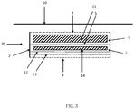
figure 3 représente une vue schématique en coupe d'un ensemble d'absorption acoustique selon un troisième mode de réalisation, ledit ensemble étant représenté monté sur un faux-plafond.
- the
figure 1 shows a schematic sectional view of a sound absorption assembly according to a first embodiment, said assembly being shown mounted on a false ceiling; - the
figure 2 shows a schematic sectional view of an acoustic absorption assembly according to a second embodiment, said assembly being shown mounted on a false ceiling; - the
figure 3 shows a schematic sectional view of an acoustic absorption assembly according to a third embodiment, said assembly being shown mounted on a false ceiling.
Pour plus de clarté, les éléments identiques ou similaires des différents modes de réalisation sont repérés par des signes de référence identiques sur l'ensemble des figures.For greater clarity, identical or similar elements of the various embodiments are identified by identical reference signs in all of the figures.
En relation avec la
L'ensemble d'absorption acoustique 1 comprend un corps 2 de forme tubulaire (désigné par la suite de corps 2 de caisson) fermé au niveau de ses extrémités respectivement par une première et une deuxième nappes souples 3, 4 tendues micro-perforées. On parlera par la suite de nappes d'extrémité 3, 4. Les nappes 3, 4 micro-perforées sont destinées à absorber les sons à hautes fréquences.The sound absorption assembly 1 comprises a
Dans le mode de réalisation décrit, le corps 2 de caisson est de forme parallélépipédique. Il est entendu que le corps 2 de caisson ne se limite pas à cette forme, ce dernier pouvant revêtir tout autre forme sans sortir du cadre de l'invention. Afin de permettre la fixation des nappes d'extrémités 3, 4, les extrémités du corps 2 de caisson sont avantageusement pourvues de moyens de fixation utilisés classiquement pour la fixation de nappes tendues. Selon une configuration particulière, il peut être prévu que le corps 2 de caisson soit formé d'un profilé ou de plusieurs profilés aboutés, chaque profilé formant une lisse de réception des moyens d'accroches ménagées au niveau de la bordure périphériques des nappes.In the embodiment described, the
L'ensemble d'absorption acoustique 1 comporte également un diaphragme plan 5 absorbant le son à basse fréquence. Dans le mode de réalisation illustré, le diaphragme est une plaque métallique 5 souple. Celle-ci est disposée à l'intérieur du corps 2 tubulaire, entre les nappes d'extrémité de manière à délimiter entre lesdites nappes deux espaces 6, 7 de préférence distincts. En d'autres termes, les espaces 6, 7 ne communiquent pas entre eux. Avantageusement, la plaque métallique 5 est disposée parallèle aux nappes d'extrémités 3, 4.The sound absorption assembly 1 also includes a
Selon un mode de réalisation particulièrement avantageux, la plaque métallique 5 est fixée au corps 2 de caisson par l'intermédiaire d'un système de fixation pourvu de moyens d'amortissement de vibrations (non représentés). Les moyens d'amortissement consistent en une ou plusieurs pièces réalisée(s) en un matériau souple de manière à permettre l'absorption des vibrations entre la plaque métallique 5 lorsque celle-ci vibre sous l'action d'ondes acoustiques et le corps 2 de caisson supportant ladite plaque. La plaque métallique 5 peut ainsi vibrer et absorber les basses fréquences sans que l'ensemble acoustique 1 ne vibre également. A titre d'exemple, les moyens d'amortissement sont des Silent Blocs®.According to a particularly advantageous embodiment, the
La plaque métallique 5 est avantageusement située à égale distance des nappes d'extrémités 3, 4.The
L'ensemble acoustique 1 est monté de manière à présenter l'une des nappes d'extrémité 3, 4 en vis-à-vis du faux-plafond 50, le corps 2de caisson s'étendant sensiblement perpendiculairement au plan du faux-plafond 50. L'ensemble acoustique 1 est placé à une certaine distance du faux plafond 50 de façon à doubler les surfaces traitées acoustiquement. En effet, en étant placé à une certaine distance du faux plafond 50, l'ensemble acoustique 1 offre une surface haute (correspondant à la nappe d'extrémité 3) et une surface basse (correspondant à nappe d'extrémité 4) micro-perforées absorbant les sons à hautes fréquences. Afin que l'ensemble acoustique 1 puisse ainsi faire office de double caisson acoustique, il convient de placer l'ensemble acoustique 1 à une distance de 2 centimètres au moins du faux plafond. Par la suite, on désignera par nappe d'extrémité supérieure 3, la nappe d'extrémité la plus proche du faux-plafond 50 et par nappe d'extrémité inférieure 4, la nappe d'extrémité située la plus éloignée du faux-plafond 50.The acoustic assembly 1 is mounted so as to have one of the end plies 3, 4 facing the
Dans le mode de réalisation illustré sur la
L'ensemble acoustique 10 comporte en outre des moyens lumineux 8 ménagés dans l'espace inférieur 7 (espace délimité entre la plaque métallique 5 et la plaque métallique inférieure 4). Les moyens lumineux 8 sont fixés, directement ou indirectement sur la face inférieure de la plaque métallique 5, ainsi que sur la portion de paroi du corps 2 de caisson située sous la plaque métallique 5. Il est bien entendu évident que l'invention ne se limite pas à cette configuration, les moyens lumineux 8 pouvant être prévus seulement sur la plaque métallique 5 ou seulement sur la portion de paroi du corps 2 de caisson.The
Avantageusement, l'ensemble acoustique 10 comporte une nappe interne 9 souple intercalée entre la plaque métallique inférieure 4 et la plaque métallique 5. la nappe interne 9 est dépourvue de perforation. Selon la puissance d'éclairage des moyens lumineux 8, la nappe interne 9 sera translucide ou non. La nappe interne 9 est disposée parallèle aux nappes d'extrémités 3, 4.Advantageously, the
L'ensemble acoustique 10 comporte en outre un panneau de matériau(x) poreux absorbant(s) acoustique(s) 11 intercalé entre la nappe d'extrémité 3 et la plaque métallique 5. Cela permet ainsi d'améliorer l'isolation acoustique. Il est bien entendu évident que si l'ensemble d'absorption ne comporte pas de moyen lumineux, un panneau de matériau(x) poreux absorbant(s) 11 pourrait également être prévu dans l'espace inférieur 7 délimité par la plaque métallique 5 et la nappe d'extrémité inférieure 4 , en remplacement ou en complément de celui disposé dans l'espace supérieur 6. Par ailleurs, dans le mode de réalisation illustré, panneau de matériau(x) poreux 11 est formé d'une seule pièce et rempli l'ensemble de l'espace acoustique supérieur. Il est bien entendu évident que le panneau de matériau(x) poreux 11 pourrait être formé de plusieurs couches d'un même ou de différents matériau(x) poreu(x) et pourrait également présenter des dimensions inférieures, notamment pour limiter le poids de l'ensemble acoustique.The
Dans le mode de réalisation illustré sur la
L'ensemble d'absorption acoustique 20 comporte en outre deux nappes internes 12, 13 souples micro-perforées, intercalées entre la nappe d'extrémité inférieure 4 et la plaque métallique 5. Les nappes internes 12, 13 sont disposées parallèles entre elles et à la plaque métallique 5. Afin d'améliorer l'isolation acoustique, deux panneaux de matériau(x) poreux absorbant(s) acoustique(s) 11, 14, l'un étant intercalé étant entre la plaque métallique 5 est la nappe interne 12 adjacente, l'autre étant intercalé entre la plaque métallique 5 et la nappe d'extrémité supérieure 3. Il est bien entendu évident que l'invention ne se limite pas à cette configuration. Il peut être prévu par exemple un ensemble d'absorption acoustique comprenant une seule ou plus de deux nappes internes 12, 13 acoustiques (ie. micro-perforées), celles-ci pouvant être placées dans l'un ou/et l'autre espace 6, 7 délimité par la plaque métallique 5. Par ailleurs, l'ensemble d'absorption 20 peut être prévu sans panneau de matériau(x) poreux absorbant(s) ou avec un seul, dans ce cas disposé soit dans l'espace supérieur 6 soit dans l'espace inférieur 7. Par ailleurs, dans le mode de réalisation illustré, les panneaux de matériau(x) poreux absorbant(s) 11, 12 sont formés d'une seule pièce et remplissent l'ensemble des espaces acoustique. Il est bien entendu évident que les panneaux 11, 12 pourraient être formés de plusieurs couches d'un même ou de différents matériau(x) absorbant(s) et pourraient également présenter des dimensions inférieures notamment pour limiter le poids de l'ensemble acoustique.The
Dans les modes de réalisation décrits, les nappes d'extrémité 3, 4 sont représentées disposées pour s'étendre dans un plan contenant les bords d'extrémité 21, 22, 23, 24 du corps 2 de caisson. Il peut être prévu également que ces nappes d'extrémité soient disposées au niveau des extrémités du corps 2 de caisson mais dans un plan légèrement décalé par rapport au plan passant par les bords d'extrémité 21, 22, 23, 24 du corps 2 de caisson.In the embodiments described, the end plies 3, 4 are shown arranged to extend in a plane containing the end edges 21, 22, 23, 24 of the
Par ailleurs, dans les modes de réalisation précédemment décrits, le diaphragme choisi est une plaque métallique. Il est bien entendu évident que la description ci-dessus s'applique également avec des diaphragmes autres qu'une plaque métallique.Furthermore, in the embodiments described above, the diaphragm chosen is a metal plate. It is of course obvious that the above description also applies with diaphragms other than a metal plate.
Dans les modes de réalisation précédemment décrits, la fausse paroi en regard de laquelle l'ensemble acoustique est placé est un faux plafond, l'ensemble formant alors un ensemble suspendu horizontalement. Il est bien entendu évident que la fausse paroi en regard de laquelle l'ensemble acoustique est placé peut être également un mur, l'ensemble acoustique formant alors un ensemble suspendu verticalement. Selon un mode de réalisation particulier, il peut être prévu également un ensemble acoustique arrangé pour présenter une partie destinée à être placée en regard du plafond et une autre partie placée en regard du mur, l'ensemble acoustique formant alors un ensemble suspendu horizontalement et verticalement.In the embodiments described above, the false wall opposite which the acoustic assembly is placed is a false ceiling, the assembly then forming a horizontally suspended assembly. It is of course obvious that the false wall opposite which the acoustic assembly is placed can also be a wall, the acoustic assembly then forming a vertically suspended assembly. According to a particular embodiment, there may also be provided an acoustic assembly arranged to present a part intended to be placed facing the ceiling and another part placed facing the wall, the acoustic assembly then forming a horizontally and vertically suspended assembly. .
S'il est décrit précédemment le montage d'un seul ensemble acoustique sur une fausse paroi, on comprend bien qu'il peut être prévu une installation dans laquelle la fausse paroi est équipée de plusieurs ensembles acoustiques.If the mounting of a single acoustic assembly on a false wall has been described above, it will be understood that an installation may be provided in which the false wall is equipped with several acoustic assemblies.
Par ailleurs, dans les modes de réalisation précédemment décrit, l'ensemble acoustique est associé à une fausse paroi, et en l'espèce un faux plafond. Il est bien entendu évident que l'ensemble acoustique selon l'invention pourrait être également mis en œuvre directement sur un plafond ou un mur.Furthermore, in the embodiments described above, the acoustic assembly is associated with a false wall, and in this case a false ceiling. It is of course obvious that the acoustic assembly according to the invention could also be implemented directly on a ceiling or a wall.
L'invention est décrite dans ce qui précède à titre d'exemple. Il est entendu que l'homme du métier est à même de réaliser différentes variantes de réalisation de l'invention sans pour autant sortir du cadre de l'invention qui est définie par le jeu de revendications.The invention is described in the foregoing by way of example. He is heard that a person skilled in the art is able to carry out different variant embodiments of the invention without thereby departing from the scope of the invention which is defined by the set of claims.
Claims (12)
- An acoustic-absorption assembly (1, 10, 20) comprising a body (2) of tubular shape having ends closed respectively by a first and a second micro-perforated flexible sheet (3, 4), characterised in that the acoustic-absorption assembly (1, 10, 20) comprises at least one plane diaphragm absorbing the low-frequency sound arranged inside the tubular body (2), between the micro-perforated flexible sheets (3, 4), so as to delimit two spaces (6, 7) between the said sheets.
- An acoustic-absorption assembly (1, 10, 20) according to claim 1, characterized in that the diaphragm is attached to the body (2) via vibration-damping means.
- An acoustic-absorption assembly (1, 10, 20) according to claim 1 or claim 2, characterized in that it comprises at least one internal flexible sheet (9, 12, 13) inserted between at least one of the micro-perforated flexible sheets (3, 4) and the diaphragm.
- An acoustic-absorption assembly (1, 10, 20) according to claim 3, characterised in that the inner flexible sheet (9, 12, 13) is micro-perforated.
- An acoustic-absorption assembly (1, 10, 20) according to claim 3, characterized in that the inner flexible sheet (9, 12, 13) is free of perforations.
- An acoustic-absorption assembly (1, 10, 20) according to any one of claims 1 to 5, characterized in that it comprises at least one panel of absorbent porous material interposed between at least one of the flexible sheets (3, 4, 9, 12, 13) and the diaphragm.
- An acoustic-absorption assembly (1, 10, 20) according to any one of claims 1 to 6, characterised in that it comprises luminous means (8) provided in one of the spaces (6, 7).
- An acoustic-absorption assembly(1, 10, 20) according to any one of claims 1 to 7, characterised in that the diaphragm is a flexible metal plate (5).
- An acoustic-absorption assembly(1, 10, 20) according to claim 8, characterized in that the metal plate (5) is arranged parallel to the flexible sheets (3, 4, 9, 12, 13).
- An acoustic-absorption assembly (1, 10, 20) according to any one of claims 1 to 9, characterized in that at least one of the flexible sheets is translucent.
- An installation comprising a false wall and at least one sound-absorption assembly (1, 10, 20) according to any of the preceding claims, said assembly being fixed to the false wall at a distance greater than or equal to a limit value.
- An installation according to claim 11, characterised in that the limit value is about 2 centimetres.
Applications Claiming Priority (2)
| Application Number | Priority Date | Filing Date | Title |
|---|---|---|---|
| FR1451735A FR3018384B1 (en) | 2014-03-04 | 2014-03-04 | ACOUSTIC ABSORPTION ASSEMBLY WITH HIGH AND LOW FREQUENCIES |
| PCT/FR2015/050509 WO2015132521A1 (en) | 2014-03-04 | 2015-03-03 | High and low frequency sound absorption assembly |
Publications (2)
| Publication Number | Publication Date |
|---|---|
| EP3114678A1 EP3114678A1 (en) | 2017-01-11 |
| EP3114678B1 true EP3114678B1 (en) | 2021-09-15 |
Family
ID=50473682
Family Applications (1)
| Application Number | Title | Priority Date | Filing Date |
|---|---|---|---|
| EP15713974.2A Active EP3114678B1 (en) | 2014-03-04 | 2015-03-03 | High and low frequency sound absorption assembly |
Country Status (9)
| Country | Link |
|---|---|
| US (1) | US10109269B2 (en) |
| EP (1) | EP3114678B1 (en) |
| CN (1) | CN106103858B (en) |
| AU (1) | AU2015225964B2 (en) |
| BR (1) | BR112016019867B1 (en) |
| CA (1) | CA2941314C (en) |
| DK (1) | DK3114678T3 (en) |
| FR (1) | FR3018384B1 (en) |
| WO (1) | WO2015132521A1 (en) |
Families Citing this family (9)
| Publication number | Priority date | Publication date | Assignee | Title |
|---|---|---|---|---|
| FR3000509B1 (en) * | 2012-12-31 | 2015-01-16 | Jean-Marc Scherrer | SEALED AND ACOUSTICALLY ABSORBENT ASSEMBLY FOR FALSE WALL |
| US10134379B2 (en) * | 2016-03-01 | 2018-11-20 | Guardian Glass, LLC | Acoustic wall assembly having double-wall configuration and passive noise-disruptive properties, and/or method of making and/or using the same |
| US10354638B2 (en) | 2016-03-01 | 2019-07-16 | Guardian Glass, LLC | Acoustic wall assembly having active noise-disruptive properties, and/or method of making and/or using the same |
| CN106482049A (en) * | 2016-11-18 | 2017-03-08 | 广东环境保护工程职业学院 | Sound absorption light fixture |
| US10373626B2 (en) | 2017-03-15 | 2019-08-06 | Guardian Glass, LLC | Speech privacy system and/or associated method |
| US10304473B2 (en) | 2017-03-15 | 2019-05-28 | Guardian Glass, LLC | Speech privacy system and/or associated method |
| US10726855B2 (en) | 2017-03-15 | 2020-07-28 | Guardian Glass, Llc. | Speech privacy system and/or associated method |
| US11114080B2 (en) * | 2018-08-27 | 2021-09-07 | Toyota Motor Engineering & Manufacturing North America, Inc. | Duct sound absorber |
| WO2020095205A1 (en) * | 2018-11-09 | 2020-05-14 | 3M Innovative Properties Company | Blanking panels including acoustic absorbing materials |
Family Cites Families (24)
| Publication number | Priority date | Publication date | Assignee | Title |
|---|---|---|---|---|
| US1754411A (en) * | 1927-11-10 | 1930-04-15 | United States Gypsum Co | Sound-insulating construction |
| US2000806A (en) * | 1932-05-18 | 1935-05-07 | Macoustic Engineering Company | Method of and apparatus for sound modification |
| US2132642A (en) * | 1932-07-21 | 1938-10-11 | Johns Manville | Sound absorbing unit |
| US2159488A (en) * | 1935-08-01 | 1939-05-23 | Johns Manville | Perforated membrane |
| US2177393A (en) * | 1937-06-08 | 1939-10-24 | Johns Manville | Sound absorbing structure |
| GB614404A (en) * | 1945-08-27 | 1948-12-15 | Cementation Co Ltd | Improvements in or relating to means for reducing the sound effect of the passage of air or other gases through conduits |
| US3253675A (en) * | 1955-01-24 | 1966-05-31 | Bolt Beranek & Newman | Light-transmitting acoustic absorber and method |
| US2966954A (en) * | 1957-07-11 | 1961-01-03 | Celotex Corp | Acoustical correction element |
| US6617002B2 (en) * | 1998-07-24 | 2003-09-09 | Minnesota Mining And Manufacturing Company | Microperforated polymeric film for sound absorption and sound absorber using same |
| US6367581B1 (en) * | 2000-05-25 | 2002-04-09 | Otis Elevator Company | Sound absorbing light fixture |
| JP4050632B2 (en) * | 2003-02-24 | 2008-02-20 | 株式会社神戸製鋼所 | Sound absorbing structure |
| KR100787297B1 (en) * | 2003-09-05 | 2007-12-20 | 가부시키가이샤 고베 세이코쇼 | Sound absorbing structure and method of producing the same |
| FR2867797A1 (en) * | 2004-03-17 | 2005-09-23 | Jean Marc Scherrer | Luminous ceiling, has shaft which is driven in rotation by electric motor and having set of revolving drums and around which straps rotate, where straps are fixed on opposite sides of case |
| WO2008007737A1 (en) | 2006-07-13 | 2008-01-17 | Sumitomo Metal Industries, Ltd. | Bend pipe and process for producing the same |
| CN101460993B (en) * | 2006-07-20 | 2011-10-05 | 株式会社神户制钢所 | Solid-borne sound reduction structure |
| WO2008017737A1 (en) * | 2006-08-10 | 2008-02-14 | Brevetix | Sound-absorbing assembly |
| US8525402B2 (en) * | 2006-09-11 | 2013-09-03 | 3M Innovative Properties Company | Illumination devices and methods for making the same |
| US8100225B2 (en) * | 2006-09-13 | 2012-01-24 | Nucore Technologies Inc. | Room dampening panel |
| DE102008017357B4 (en) * | 2008-04-04 | 2014-01-16 | Airbus Operations Gmbh | Acoustically optimized cabin wall element and its use |
| CN101650938A (en) * | 2008-08-15 | 2010-02-17 | 吴哲 | Method and device used for air environment sound absorption and method for manufacturing sound insulation chamber |
| DE102009020996A1 (en) | 2009-05-12 | 2010-11-18 | Aksys Gmbh | Airborne sound insulating material structure |
| FR2970009B1 (en) * | 2010-12-30 | 2021-06-11 | Normalu | ACOUSTICALLY ABSORBENT PACKAGE |
| US9194124B2 (en) * | 2011-12-09 | 2015-11-24 | 3M Innovative Properties Company | Acoustic light panel |
| US9390702B2 (en) * | 2014-03-27 | 2016-07-12 | Acoustic Metamaterials Inc. | Acoustic metamaterial architectured composite layers, methods of manufacturing the same, and methods for noise control using the same |
-
2014
- 2014-03-04 FR FR1451735A patent/FR3018384B1/en active Active
-
2015
- 2015-03-03 US US15/121,408 patent/US10109269B2/en active Active
- 2015-03-03 BR BR112016019867-0A patent/BR112016019867B1/en active IP Right Grant
- 2015-03-03 CN CN201580011760.5A patent/CN106103858B/en active Active
- 2015-03-03 AU AU2015225964A patent/AU2015225964B2/en active Active
- 2015-03-03 DK DK15713974.2T patent/DK3114678T3/en active
- 2015-03-03 CA CA2941314A patent/CA2941314C/en active Active
- 2015-03-03 EP EP15713974.2A patent/EP3114678B1/en active Active
- 2015-03-03 WO PCT/FR2015/050509 patent/WO2015132521A1/en active Application Filing
Also Published As
| Publication number | Publication date |
|---|---|
| AU2015225964B2 (en) | 2020-06-25 |
| CN106103858A (en) | 2016-11-09 |
| BR112016019867B1 (en) | 2022-10-04 |
| CN106103858B (en) | 2021-11-16 |
| BR112016019867A2 (en) | 2017-08-15 |
| US20160365079A1 (en) | 2016-12-15 |
| US10109269B2 (en) | 2018-10-23 |
| EP3114678A1 (en) | 2017-01-11 |
| CA2941314A1 (en) | 2015-09-11 |
| FR3018384A1 (en) | 2015-09-11 |
| CA2941314C (en) | 2022-04-26 |
| AU2015225964A1 (en) | 2016-08-25 |
| WO2015132521A1 (en) | 2015-09-11 |
| DK3114678T3 (en) | 2021-12-20 |
| FR3018384B1 (en) | 2016-03-11 |
Similar Documents
| Publication | Publication Date | Title |
|---|---|---|
| EP3114678B1 (en) | High and low frequency sound absorption assembly | |
| EP2472018B1 (en) | Acoustically absorbing assembly | |
| EP3371984B1 (en) | Multi-glazed window incorporating a noise reduction device | |
| EP2938793B1 (en) | Wall comprising a dustproof acoustically absorbing assembly | |
| EP2054562B1 (en) | Sound-absorbing assembly | |
| EP2447432B1 (en) | Device for hanging an acoustical treatment element | |
| FR2881765A1 (en) | Sound absorbent assembly for use in apartment, has poly vinyl chloride canvas with two series of micro-perforations having respective small and large surfaces and distributed in regular manner on square shaped meshing on canvas | |
| FR3043588A1 (en) | MULTILAYER ACOUSTIC PANEL | |
| EP0560702B1 (en) | Audio-video recording studio or concert hall | |
| CA2757170A1 (en) | Acoustic panel for receiving, emitting or absorbing sounds | |
| FR2881768A1 (en) | PLATE PLATE PROVIDING ACOUSTIC INSULATION | |
| EP3224424A1 (en) | Stretched-web structure for producing a false ceiling or a dropped ceiling box | |
| CA2455032A1 (en) | Soundproofing panel | |
| EP3736465B1 (en) | Resonance absorber for a construction wall and construction element with resonance absorbers | |
| BE1017303A6 (en) | PASSIVE SOUND ABSORBER FOR ACOUSTIC CORRECTION WITHIN A BUILDING. | |
| FR3050217A1 (en) | ELEMENT OR PART OF PARTITION INCORPORATING A SOUND RESTITUTION DEVICE | |
| EP4172448A1 (en) | Sound spacer | |
| EP3090903B1 (en) | Motor vehicle wall having two skins provided with protrusions and sandwiching a core | |
| WO2020260622A1 (en) | Double-walled unit | |
| FR3006803A1 (en) | ASSEMBLY OF ACOUSTIC ELEMENTS, OR IDIOPHONIC SYSTEMS, FOR MODIFYING THE ACOUSTIC PROPERTIES OF A SPACE, ITS USE AND CORRESPONDING METHODS | |
| FR3083580A1 (en) | DEVICE FOR DAMPING VIBRATIONS OF A MECHANICAL COMPONENT | |
| CA2454998A1 (en) | Mechanical structure with a modifiable vibration property | |
| FR2737514A1 (en) | Anti-noise screen for roads and railways - comprises vertical H section posts for holding panels which comprise sound absorbing layer butt jointed to cover posts, sound reflecting layer being on one sound absorbing surface | |
| FR3026123A1 (en) | REINFORCED WALL PANEL, IN PARTICULAR FOR SHOWER SPACE | |
| FR3028346A1 (en) | PERCUSSION MUSIC INSTRUMENT. |
Legal Events
| Date | Code | Title | Description |
|---|---|---|---|
| STAA | Information on the status of an ep patent application or granted ep patent |
Free format text: STATUS: THE INTERNATIONAL PUBLICATION HAS BEEN MADE |
|
| PUAI | Public reference made under article 153(3) epc to a published international application that has entered the european phase |
Free format text: ORIGINAL CODE: 0009012 |
|
| STAA | Information on the status of an ep patent application or granted ep patent |
Free format text: STATUS: REQUEST FOR EXAMINATION WAS MADE |
|
| 17P | Request for examination filed |
Effective date: 20160808 |
|
| AK | Designated contracting states |
Kind code of ref document: A1 Designated state(s): AL AT BE BG CH CY CZ DE DK EE ES FI FR GB GR HR HU IE IS IT LI LT LU LV MC MK MT NL NO PL PT RO RS SE SI SK SM TR |
|
| AX | Request for extension of the european patent |
Extension state: BA ME |
|
| DAV | Request for validation of the european patent (deleted) | ||
| DAX | Request for extension of the european patent (deleted) | ||
| STAA | Information on the status of an ep patent application or granted ep patent |
Free format text: STATUS: EXAMINATION IS IN PROGRESS |
|
| 17Q | First examination report despatched |
Effective date: 20190411 |
|
| STAA | Information on the status of an ep patent application or granted ep patent |
Free format text: STATUS: EXAMINATION IS IN PROGRESS |
|
| GRAP | Despatch of communication of intention to grant a patent |
Free format text: ORIGINAL CODE: EPIDOSNIGR1 |
|
| STAA | Information on the status of an ep patent application or granted ep patent |
Free format text: STATUS: GRANT OF PATENT IS INTENDED |
|
| INTG | Intention to grant announced |
Effective date: 20210421 |
|
| GRAS | Grant fee paid |
Free format text: ORIGINAL CODE: EPIDOSNIGR3 |
|
| GRAA | (expected) grant |
Free format text: ORIGINAL CODE: 0009210 |
|
| STAA | Information on the status of an ep patent application or granted ep patent |
Free format text: STATUS: THE PATENT HAS BEEN GRANTED |
|
| AK | Designated contracting states |
Kind code of ref document: B1 Designated state(s): AL AT BE BG CH CY CZ DE DK EE ES FI FR GB GR HR HU IE IS IT LI LT LU LV MC MK MT NL NO PL PT RO RS SE SI SK SM TR |
|
| RAP3 | Party data changed (applicant data changed or rights of an application transferred) |
Owner name: SCHERRER, JEAN-MARC |
|
| REG | Reference to a national code |
Ref country code: CH Ref legal event code: EP Ref country code: GB Ref legal event code: FG4D Free format text: NOT ENGLISH |
|
| RIN1 | Information on inventor provided before grant (corrected) |
Inventor name: SCHERRER, JEAN-MARC |
|
| REG | Reference to a national code |
Ref country code: DE Ref legal event code: R096 Ref document number: 602015073282 Country of ref document: DE |
|
| REG | Reference to a national code |
Ref country code: IE Ref legal event code: FG4D Free format text: LANGUAGE OF EP DOCUMENT: FRENCH |
|
| REG | Reference to a national code |
Ref country code: AT Ref legal event code: REF Ref document number: 1431123 Country of ref document: AT Kind code of ref document: T Effective date: 20211015 |
|
| REG | Reference to a national code |
Ref country code: DK Ref legal event code: T3 Effective date: 20211213 |
|
| REG | Reference to a national code |
Ref country code: LT Ref legal event code: MG9D |
|
| REG | Reference to a national code |
Ref country code: NL Ref legal event code: MP Effective date: 20210915 |
|
| PG25 | Lapsed in a contracting state [announced via postgrant information from national office to epo] |
Ref country code: SE Free format text: LAPSE BECAUSE OF FAILURE TO SUBMIT A TRANSLATION OF THE DESCRIPTION OR TO PAY THE FEE WITHIN THE PRESCRIBED TIME-LIMIT Effective date: 20210915 Ref country code: RS Free format text: LAPSE BECAUSE OF FAILURE TO SUBMIT A TRANSLATION OF THE DESCRIPTION OR TO PAY THE FEE WITHIN THE PRESCRIBED TIME-LIMIT Effective date: 20210915 Ref country code: HR Free format text: LAPSE BECAUSE OF FAILURE TO SUBMIT A TRANSLATION OF THE DESCRIPTION OR TO PAY THE FEE WITHIN THE PRESCRIBED TIME-LIMIT Effective date: 20210915 Ref country code: FI Free format text: LAPSE BECAUSE OF FAILURE TO SUBMIT A TRANSLATION OF THE DESCRIPTION OR TO PAY THE FEE WITHIN THE PRESCRIBED TIME-LIMIT Effective date: 20210915 Ref country code: NO Free format text: LAPSE BECAUSE OF FAILURE TO SUBMIT A TRANSLATION OF THE DESCRIPTION OR TO PAY THE FEE WITHIN THE PRESCRIBED TIME-LIMIT Effective date: 20211215 Ref country code: BG Free format text: LAPSE BECAUSE OF FAILURE TO SUBMIT A TRANSLATION OF THE DESCRIPTION OR TO PAY THE FEE WITHIN THE PRESCRIBED TIME-LIMIT Effective date: 20211215 Ref country code: LT Free format text: LAPSE BECAUSE OF FAILURE TO SUBMIT A TRANSLATION OF THE DESCRIPTION OR TO PAY THE FEE WITHIN THE PRESCRIBED TIME-LIMIT Effective date: 20210915 |
|
| REG | Reference to a national code |
Ref country code: AT Ref legal event code: MK05 Ref document number: 1431123 Country of ref document: AT Kind code of ref document: T Effective date: 20210915 |
|
| PG25 | Lapsed in a contracting state [announced via postgrant information from national office to epo] |
Ref country code: LV Free format text: LAPSE BECAUSE OF FAILURE TO SUBMIT A TRANSLATION OF THE DESCRIPTION OR TO PAY THE FEE WITHIN THE PRESCRIBED TIME-LIMIT Effective date: 20210915 Ref country code: GR Free format text: LAPSE BECAUSE OF FAILURE TO SUBMIT A TRANSLATION OF THE DESCRIPTION OR TO PAY THE FEE WITHIN THE PRESCRIBED TIME-LIMIT Effective date: 20211216 |
|
| PG25 | Lapsed in a contracting state [announced via postgrant information from national office to epo] |
Ref country code: AT Free format text: LAPSE BECAUSE OF FAILURE TO SUBMIT A TRANSLATION OF THE DESCRIPTION OR TO PAY THE FEE WITHIN THE PRESCRIBED TIME-LIMIT Effective date: 20210915 |
|
| PG25 | Lapsed in a contracting state [announced via postgrant information from national office to epo] |
Ref country code: IS Free format text: LAPSE BECAUSE OF FAILURE TO SUBMIT A TRANSLATION OF THE DESCRIPTION OR TO PAY THE FEE WITHIN THE PRESCRIBED TIME-LIMIT Effective date: 20220115 Ref country code: SM Free format text: LAPSE BECAUSE OF FAILURE TO SUBMIT A TRANSLATION OF THE DESCRIPTION OR TO PAY THE FEE WITHIN THE PRESCRIBED TIME-LIMIT Effective date: 20210915 Ref country code: SK Free format text: LAPSE BECAUSE OF FAILURE TO SUBMIT A TRANSLATION OF THE DESCRIPTION OR TO PAY THE FEE WITHIN THE PRESCRIBED TIME-LIMIT Effective date: 20210915 Ref country code: RO Free format text: LAPSE BECAUSE OF FAILURE TO SUBMIT A TRANSLATION OF THE DESCRIPTION OR TO PAY THE FEE WITHIN THE PRESCRIBED TIME-LIMIT Effective date: 20210915 Ref country code: PT Free format text: LAPSE BECAUSE OF FAILURE TO SUBMIT A TRANSLATION OF THE DESCRIPTION OR TO PAY THE FEE WITHIN THE PRESCRIBED TIME-LIMIT Effective date: 20220117 Ref country code: PL Free format text: LAPSE BECAUSE OF FAILURE TO SUBMIT A TRANSLATION OF THE DESCRIPTION OR TO PAY THE FEE WITHIN THE PRESCRIBED TIME-LIMIT Effective date: 20210915 Ref country code: NL Free format text: LAPSE BECAUSE OF FAILURE TO SUBMIT A TRANSLATION OF THE DESCRIPTION OR TO PAY THE FEE WITHIN THE PRESCRIBED TIME-LIMIT Effective date: 20210915 Ref country code: ES Free format text: LAPSE BECAUSE OF FAILURE TO SUBMIT A TRANSLATION OF THE DESCRIPTION OR TO PAY THE FEE WITHIN THE PRESCRIBED TIME-LIMIT Effective date: 20210915 Ref country code: EE Free format text: LAPSE BECAUSE OF FAILURE TO SUBMIT A TRANSLATION OF THE DESCRIPTION OR TO PAY THE FEE WITHIN THE PRESCRIBED TIME-LIMIT Effective date: 20210915 Ref country code: CZ Free format text: LAPSE BECAUSE OF FAILURE TO SUBMIT A TRANSLATION OF THE DESCRIPTION OR TO PAY THE FEE WITHIN THE PRESCRIBED TIME-LIMIT Effective date: 20210915 Ref country code: AL Free format text: LAPSE BECAUSE OF FAILURE TO SUBMIT A TRANSLATION OF THE DESCRIPTION OR TO PAY THE FEE WITHIN THE PRESCRIBED TIME-LIMIT Effective date: 20210915 |
|
| REG | Reference to a national code |
Ref country code: DE Ref legal event code: R097 Ref document number: 602015073282 Country of ref document: DE |
|
| PLBE | No opposition filed within time limit |
Free format text: ORIGINAL CODE: 0009261 |
|
| STAA | Information on the status of an ep patent application or granted ep patent |
Free format text: STATUS: NO OPPOSITION FILED WITHIN TIME LIMIT |
|
| 26N | No opposition filed |
Effective date: 20220616 |
|
| PG25 | Lapsed in a contracting state [announced via postgrant information from national office to epo] |
Ref country code: SI Free format text: LAPSE BECAUSE OF FAILURE TO SUBMIT A TRANSLATION OF THE DESCRIPTION OR TO PAY THE FEE WITHIN THE PRESCRIBED TIME-LIMIT Effective date: 20210915 |
|
| PG25 | Lapsed in a contracting state [announced via postgrant information from national office to epo] |
Ref country code: MC Free format text: LAPSE BECAUSE OF FAILURE TO SUBMIT A TRANSLATION OF THE DESCRIPTION OR TO PAY THE FEE WITHIN THE PRESCRIBED TIME-LIMIT Effective date: 20210915 |
|
| REG | Reference to a national code |
Ref country code: BE Ref legal event code: MM Effective date: 20220331 |
|
| PG25 | Lapsed in a contracting state [announced via postgrant information from national office to epo] |
Ref country code: LU Free format text: LAPSE BECAUSE OF NON-PAYMENT OF DUE FEES Effective date: 20220303 Ref country code: IE Free format text: LAPSE BECAUSE OF NON-PAYMENT OF DUE FEES Effective date: 20220303 |
|
| PG25 | Lapsed in a contracting state [announced via postgrant information from national office to epo] |
Ref country code: BE Free format text: LAPSE BECAUSE OF NON-PAYMENT OF DUE FEES Effective date: 20220331 |
|
| PGFP | Annual fee paid to national office [announced via postgrant information from national office to epo] |
Ref country code: FR Payment date: 20230222 Year of fee payment: 9 Ref country code: DK Payment date: 20230221 Year of fee payment: 9 |
|
| PGFP | Annual fee paid to national office [announced via postgrant information from national office to epo] |
Ref country code: IT Payment date: 20230221 Year of fee payment: 9 Ref country code: GB Payment date: 20230222 Year of fee payment: 9 Ref country code: DE Payment date: 20230221 Year of fee payment: 9 |
|
| PGFP | Annual fee paid to national office [announced via postgrant information from national office to epo] |
Ref country code: CH Payment date: 20230401 Year of fee payment: 9 |
|
| PG25 | Lapsed in a contracting state [announced via postgrant information from national office to epo] |
Ref country code: HU Free format text: LAPSE BECAUSE OF FAILURE TO SUBMIT A TRANSLATION OF THE DESCRIPTION OR TO PAY THE FEE WITHIN THE PRESCRIBED TIME-LIMIT; INVALID AB INITIO Effective date: 20150303 |