EP3113495A1 - Verfahren und vorrichtungen zur codierung und decodierung eines hdr farbbildes - Google Patents
Verfahren und vorrichtungen zur codierung und decodierung eines hdr farbbildes Download PDFInfo
- Publication number
- EP3113495A1 EP3113495A1 EP15306042.1A EP15306042A EP3113495A1 EP 3113495 A1 EP3113495 A1 EP 3113495A1 EP 15306042 A EP15306042 A EP 15306042A EP 3113495 A1 EP3113495 A1 EP 3113495A1
- Authority
- EP
- European Patent Office
- Prior art keywords
- color
- sdr
- dynamic range
- color picture
- standard dynamic
- Prior art date
- Legal status (The legal status is an assumption and is not a legal conclusion. Google has not performed a legal analysis and makes no representation as to the accuracy of the status listed.)
- Withdrawn
Links
- 238000000034 method Methods 0.000 title claims abstract description 87
- 238000013507 mapping Methods 0.000 claims description 69
- 239000003086 colorant Substances 0.000 claims description 33
- 230000005540 biological transmission Effects 0.000 claims description 15
- 238000004590 computer program Methods 0.000 claims description 3
- 230000006870 function Effects 0.000 description 36
- 239000011159 matrix material Substances 0.000 description 29
- 238000010586 diagram Methods 0.000 description 24
- 238000012886 linear function Methods 0.000 description 22
- 238000003860 storage Methods 0.000 description 18
- 238000004891 communication Methods 0.000 description 15
- 230000000875 corresponding effect Effects 0.000 description 14
- 230000008569 process Effects 0.000 description 12
- 238000012937 correction Methods 0.000 description 11
- 230000006978 adaptation Effects 0.000 description 7
- 230000008859 change Effects 0.000 description 7
- 230000003287 optical effect Effects 0.000 description 7
- 238000009826 distribution Methods 0.000 description 6
- 238000004519 manufacturing process Methods 0.000 description 4
- 238000012545 processing Methods 0.000 description 4
- 238000012360 testing method Methods 0.000 description 4
- 101100452680 Arabidopsis thaliana INVC gene Proteins 0.000 description 3
- 241000023320 Luma <angiosperm> Species 0.000 description 3
- 238000012888 cubic function Methods 0.000 description 3
- 230000001965 increasing effect Effects 0.000 description 3
- OSWPMRLSEDHDFF-UHFFFAOYSA-N methyl salicylate Chemical compound COC(=O)C1=CC=CC=C1O OSWPMRLSEDHDFF-UHFFFAOYSA-N 0.000 description 3
- 238000012986 modification Methods 0.000 description 3
- 230000004048 modification Effects 0.000 description 3
- 238000009877 rendering Methods 0.000 description 3
- 238000012546 transfer Methods 0.000 description 3
- 238000003491 array Methods 0.000 description 2
- 230000008901 benefit Effects 0.000 description 2
- 230000000670 limiting effect Effects 0.000 description 2
- 239000000203 mixture Substances 0.000 description 2
- 230000008447 perception Effects 0.000 description 2
- 229920001690 polydopamine Polymers 0.000 description 2
- 238000004321 preservation Methods 0.000 description 2
- 239000004065 semiconductor Substances 0.000 description 2
- 230000000007 visual effect Effects 0.000 description 2
- 230000003044 adaptive effect Effects 0.000 description 1
- 238000004737 colorimetric analysis Methods 0.000 description 1
- 230000000295 complement effect Effects 0.000 description 1
- 238000007906 compression Methods 0.000 description 1
- 230000006835 compression Effects 0.000 description 1
- 230000002596 correlated effect Effects 0.000 description 1
- 230000000694 effects Effects 0.000 description 1
- 238000005516 engineering process Methods 0.000 description 1
- 230000002708 enhancing effect Effects 0.000 description 1
- 238000009472 formulation Methods 0.000 description 1
- 238000005286 illumination Methods 0.000 description 1
- 230000010354 integration Effects 0.000 description 1
- 230000003993 interaction Effects 0.000 description 1
- 230000007935 neutral effect Effects 0.000 description 1
- 230000002035 prolonged effect Effects 0.000 description 1
- 230000009467 reduction Effects 0.000 description 1
- 238000012552 review Methods 0.000 description 1
- 238000001228 spectrum Methods 0.000 description 1
- 230000000153 supplemental effect Effects 0.000 description 1
Images


Classifications
-
- G—PHYSICS
- G06—COMPUTING; CALCULATING OR COUNTING
- G06T—IMAGE DATA PROCESSING OR GENERATION, IN GENERAL
- G06T5/00—Image enhancement or restoration
- G06T5/10—Image enhancement or restoration using non-spatial domain filtering
-
- G—PHYSICS
- G06—COMPUTING; CALCULATING OR COUNTING
- G06T—IMAGE DATA PROCESSING OR GENERATION, IN GENERAL
- G06T5/00—Image enhancement or restoration
- G06T5/90—Dynamic range modification of images or parts thereof
- G06T5/92—Dynamic range modification of images or parts thereof based on global image properties
-
- H—ELECTRICITY
- H04—ELECTRIC COMMUNICATION TECHNIQUE
- H04N—PICTORIAL COMMUNICATION, e.g. TELEVISION
- H04N19/00—Methods or arrangements for coding, decoding, compressing or decompressing digital video signals
- H04N19/10—Methods or arrangements for coding, decoding, compressing or decompressing digital video signals using adaptive coding
- H04N19/169—Methods or arrangements for coding, decoding, compressing or decompressing digital video signals using adaptive coding characterised by the coding unit, i.e. the structural portion or semantic portion of the video signal being the object or the subject of the adaptive coding
- H04N19/17—Methods or arrangements for coding, decoding, compressing or decompressing digital video signals using adaptive coding characterised by the coding unit, i.e. the structural portion or semantic portion of the video signal being the object or the subject of the adaptive coding the unit being an image region, e.g. an object
- H04N19/172—Methods or arrangements for coding, decoding, compressing or decompressing digital video signals using adaptive coding characterised by the coding unit, i.e. the structural portion or semantic portion of the video signal being the object or the subject of the adaptive coding the unit being an image region, e.g. an object the region being a picture, frame or field
-
- H—ELECTRICITY
- H04—ELECTRIC COMMUNICATION TECHNIQUE
- H04N—PICTORIAL COMMUNICATION, e.g. TELEVISION
- H04N19/00—Methods or arrangements for coding, decoding, compressing or decompressing digital video signals
- H04N19/10—Methods or arrangements for coding, decoding, compressing or decompressing digital video signals using adaptive coding
- H04N19/169—Methods or arrangements for coding, decoding, compressing or decompressing digital video signals using adaptive coding characterised by the coding unit, i.e. the structural portion or semantic portion of the video signal being the object or the subject of the adaptive coding
- H04N19/186—Methods or arrangements for coding, decoding, compressing or decompressing digital video signals using adaptive coding characterised by the coding unit, i.e. the structural portion or semantic portion of the video signal being the object or the subject of the adaptive coding the unit being a colour or a chrominance component
-
- H—ELECTRICITY
- H04—ELECTRIC COMMUNICATION TECHNIQUE
- H04N—PICTORIAL COMMUNICATION, e.g. TELEVISION
- H04N19/00—Methods or arrangements for coding, decoding, compressing or decompressing digital video signals
- H04N19/30—Methods or arrangements for coding, decoding, compressing or decompressing digital video signals using hierarchical techniques, e.g. scalability
-
- H—ELECTRICITY
- H04—ELECTRIC COMMUNICATION TECHNIQUE
- H04N—PICTORIAL COMMUNICATION, e.g. TELEVISION
- H04N19/00—Methods or arrangements for coding, decoding, compressing or decompressing digital video signals
- H04N19/60—Methods or arrangements for coding, decoding, compressing or decompressing digital video signals using transform coding
-
- H—ELECTRICITY
- H04—ELECTRIC COMMUNICATION TECHNIQUE
- H04N—PICTORIAL COMMUNICATION, e.g. TELEVISION
- H04N9/00—Details of colour television systems
- H04N9/77—Circuits for processing the brightness signal and the chrominance signal relative to each other, e.g. adjusting the phase of the brightness signal relative to the colour signal, correcting differential gain or differential phase
-
- H—ELECTRICITY
- H04—ELECTRIC COMMUNICATION TECHNIQUE
- H04N—PICTORIAL COMMUNICATION, e.g. TELEVISION
- H04N9/00—Details of colour television systems
- H04N9/64—Circuits for processing colour signals
- H04N9/643—Hue control means, e.g. flesh tone control
-
- H—ELECTRICITY
- H04—ELECTRIC COMMUNICATION TECHNIQUE
- H04N—PICTORIAL COMMUNICATION, e.g. TELEVISION
- H04N9/00—Details of colour television systems
- H04N9/64—Circuits for processing colour signals
- H04N9/68—Circuits for processing colour signals for controlling the amplitude of colour signals, e.g. automatic chroma control circuits
Definitions
- the present disclosure generally relates to picture/video encoding and decoding. Particularly, but not exclusively, the technical field of the present disclosure is related to encoding/decoding of both a color picture whose pixels values belong to a High Dynamic Range (HDR) and at least one color picture whose values belong to a Standard Dynamic Range (SDR) and who is obtained by a color-grading post-production operation applied on said High Dynamic Range (HDR) color picture.
- HDR High Dynamic Range
- SDR Standard Dynamic Range
- a color picture contains several arrays of samples (pixel values) in a specific picture/video format, which specifies all information relative to the pixel values of a picture (or a video), and all information, which may be used by a display and/or any other device to visualize and/or decode a picture (or video) for example.
- a color picture comprises at least one component, in the shape of a first array of samples, usually a luma (or luminance) component, and at least one another component, in the shape of at least one other array of samples.
- the same information may also be represented by a set of arrays of color samples (color component), such as the traditional tri-chromatic RGB representation.
- a pixel value is represented by a vector of c values, where c is the number of components.
- Each value of a vector is represented with a number of bits, which defines a maximal dynamic range of the pixel values.
- Standard-Dynamic-Range pictures are color pictures whose luminance values are represented with a limited dynamic usually measured in power of two or f-stops.
- SDR pictures have a dynamic around 10 fstops, i.e. a ratio 1000 between the brightest pixels and the darkest pixels in the linear domain, and are coded with a limited number of bits (most often 8 or 10 in HDTV (High Definition Television systems) and UHDTV (Ultra-High Definition Television systems) in a non-linear domain, for instance by using the ITU-R BT.709 OEFT (Optico-Electrical-Transfer-Function) ( Rec.
- ITU-R BT.709-5, April 2002 or ITU-R BT.2020 OETF ( Rec. ITU-R BT.2020-1, June 2014 ) to reduce the dynamic.
- This limited non-linear representation does not allow correct rendering of small signal variations, in particular in dark and bright luminance ranges.
- High-Dynamic-Range pictures the signal dynamic is much higher (up to 20 f-stops, a ratio one million between the brightest pixels and the darkest pixels) and a new non-linear representation is needed in order to maintain a high accuracy of the signal over its entire range.
- raw data are usually represented in floating-point format (either 32-bit or 16-bit for each component, namely float or half-float), the most popular format being openEXR half-float format (16-bit per RGB component, i.e. 48 bits per pixel) or in integers with a long representation, typically at least 16 bits.
- floating-point format either 32-bit or 16-bit for each component, namely float or half-float
- openEXR half-float format (16-bit per RGB component, i.e. 48 bits per pixel
- integers with a long representation typically at least 16 bits.
- a color gamut is a certain complete set of colors. The most common usage refers to a set of colors which can be accurately represented in a given circumstance, such as within a given color space or by a certain output device.
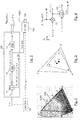
- a color gamut is sometimes defined by RGB primaries provided in the CIE1931 color space chromaticity diagram and a white point as illustrated in Fig. 1 .
- a gamut is defined in this diagram by the triangle whose vertices are the set of (x,y) coordinates of the three primaries RGB.
- the white point W is another given (x,y) point belonging to the triangle, usually close to the triangle center.
- a color volume is defined by a color space and a dynamic range of the values represented in said color space.
- a color gamut is defined by a RGB ITU-R Recommendation BT.2020 color space for UHDTV.
- An older standard, ITU-R Recommendation BT.709 defines a smaller color gamut for HDTV.
- the dynamic range is defined officially up to 100 nits (candela per square meter) for the color volume in which data are coded, although some display technologies may show brighter pixels.
- a change of gamut i.e. a transform that maps the three primaries and the white point from a gamut to another, can be performed by using a 3x3 matrix in linear RGB color space.
- a change of space from XYZ to RGB is performed by a 3x3 matrix.
- a change of gamut can be performed by a 3x3 matrix.
- a gamut change from BT.2020 linear RGB to BT.709 XYZ can be performed by a 3x3 matrix.
- High Dynamic Range pictures are color pictures whose luminance values are represented with a HDR dynamic that is higher than the dynamic of a SDR picture.
- the HDR dynamic is not yet defined by a standard but one may expect a dynamic range up to a few thousands nits.
- a HDR color volume is defined by a RGB BT.2020 color space and the values represented in said RGB color space belong to a dynamic range from 0 to 4000 nits.
- Another example of HDR color volume is defined by a RGB BT.2020 color space and the values represented in said RGB color space belong to a dynamic range from 0 to 1000 nits.
- Color-grading a picture is a process of altering/enhancing the colors of the picture (or the video).
- color-grading a picture involves a change of the color volume (color space and/or dynamic range) or a change of the color gamut relative to this picture.
- two different color-graded versions of a same picture are versions of this picture whose values are represented in different color volumes (or color gamut) or versions of the picture whose at least one of their colors has been altered/enhanced according to different color grades. This may involve user interactions.
- RGB color values composed of 3 components (Red, Green and Blue).
- the RGB color values depend on the tri-chromatic characteristics (color primaries) of the sensor.
- a HDR color-graded version of the captured picture is then obtained in order to get theatrical renders (using a specific theatrical grade).
- the values of the first color-graded version of the captured picture are represented according to a standardized YUV format such as BT.2020, which defines parameter values for UHDTV.
- the YUV format is typically performed by applying a non-linear function, so called Optical Electronic Transfer Function (OETF) on the linear RGB components to obtain non-linear components R'G'B', and then applying a color transform (usually a 3x3 matrix) on the obtained non-linear R'G'B' components to obtain the three components YUV.
- OETF Optical Electronic Transfer Function
- the first component Y is a luminance component and the two components U,V are chrominance components.
- a Colorist usually in conjunction with a Director of Photography, performs a control on the color values of the first color-graded version of the captured picture by fine-tuning/tweaking some color values in order to instill an artistic intent.
- a color-graded SDR version of the captured picture (or video) is also usually obtained in order to get a specific rendering (using a specific grading).
- the values of the color-graded SDR picture (or video) are represented according to a standardized YUV format, such as BT.709, which defines parameter values for HDTV, or again BT.2020, which defines parameter values for UHDTV.
- a 100 nits grading is applied for movies for broadcasting and consumer market distribution like Blu-ray® disks.
- the Colorist performs also a control on the color values of the color-graded SDR picture by fine-tuning/tweaking some color values in order to instill an artistic intent.
- the problem to be solved is the distribution of both the HDR and SDR color-graded versions of the captured picture (or video), i.e. the distribution of a compressed HDR picture (or video) representative of a color-graded version of a captured picture (or video) while, at the same time, distributing an associated SDR picture (or video) representative of a color-graded SDR version of said captured picture (or video).
- a trivial solution is simulcasting both these HDR and SDR color-graded pictures (or videos) on distribution infrastructure but the drawback is to virtually double the needed bandwidth compared to a legacy infrastructure adapted to broadcast a SDR picture (or video) such as HEVC main 10 profile ("High Efficiency Video Coding", SERIES H: AUDIOVISUAL AND MULTIMEDIA SYSTEMS, Recommendation ITU-T H.265, Telecommunication Standardization Sector of ITU, October 2014 ).
- Using a legacy distribution infrastructure is a requirement to accelerate the emergence of the distribution of HDR pictures (or video). Also, the bitrate shall be minimized while ensuring good quality of both SDR and HDR pictures (or videos).
- full backward compatibility may be ensured, i.e. users, equipped with legacy decoder and display, have an experience close to the artist intent, i.e. the color grade (possibly modified by the Colorist) of the SDR picture is preserved.
- the disclosure sets out to remedy at least one of the drawbacks of the prior art with a method for encoding a High Dynamic Range (HDR) color picture and at least one first Standard Dynamic Range (SDR) color picture, said method comprising:
- the term "approximation” is used since, the color remapping information helps producing an SDR picture that is visually close to the first SDR color picture, but does not guarantee any distance target, in terms of mathematical distortion between two pictures.
- Such second SDR color picture automatically obtained through a classical encoding from the HDR picture may be viewable when after being decoded, but its display would not be acceptable from the point of view of the Colorist or of the Director of Photography, if the second SDR picture does not respect the artistic intent of the Colorist.
- Determining a color remapping information permits to inform a decoder of the true grading of the considered picture that would be required by the Colorist or by the Director of Photography.
- the definition of a "color remapping information” is disclosed in the section D.3.32 entitled “ Colour remapping information SEI message semantics" of the standard ITU-T H.265 (10/2014) Series H: Audiovisual and Multimedia Systems .
- said at least one first Standard Dynamic Range (SDR) color picture is obtained from a color-graded version of said High Dynamic Range (HDR) color picture.
- the hue and perceived saturation of the color of the first imposed SDR color picture obtained from a color-graded version of said HDR color picture are thus preserved, as whished by a Colorist.
- the method ensures thus full backward compatibility with an SDR rendering, where a dedicated SDR graded is imposed, and without any additional encoding operation (and the corresponding increase of bandwidth), that would imply residual data coding between the second Standard Dynamic Range (SDR) color picture obtained from the HDR color picture.
- SDR Standard Dynamic Range
- encoding a second SDR color picture obtained from said High Dynamic Range (HDR) color picture color picture comprises:
- the colors obtained by combining together a luminance component and two chrominance components representing a SDR version of a HDR color picture do not preserve hue and perceived saturation of the colors of the HDR color picture.
- Mapping the gamut of colors of such second SDR picture onto the gamut of the colors of the HDR color picture to be encoded correct the hue and perceived saturation relatively to said HDR picture.
- the hue and perceived saturation of the color of the HDR picture are thus preserved increasing the visual quality of the decoded SDR picture whose perceived colors match the original HDR better.
- this mapping method provides a second SDR picture that is close to the initial HDR color picture, in term of perceived hue and color saturation. Therefore, compared to classical mapping methods (PQ-EOTF), this provides a second SDR picture that is more correlated to the first SDR picture issued from the colo-grading process, which has been performed starting from said HDR color picture.
- PQ-EOTF classical mapping methods
- said method further comprises transmitting said at least one piece of color remapping information.
- said at least one piece of color remapping information is distributed as a metadata associated to said second SDR picture.
- said second Standard Dynamic Range (SDR) color picture is delivered by said mapping.
- said second SDR picture represents a reduced-dynamic version of the HDR color picture
- the corresponding color remapping information is obtained from two SDR color pictures, one SDR color picture imposed by a Colorist and corresponding to a color-graded version of said HDR color picture and the other SDR color picture being delivered by a mapping of the HDR color picture.
- the present disclosure discloses the transmission of an encoded SDR color picture as a reduced-dynamic version of a native HDR color picture, such SDR color picture being also associated with at least one piece of color remapping information transmitted to a decoder.
- the decoder will receive the encoded SDR color picture as a reduced-dynamic version of a native HDR color picture and its at least one associated piece of color remapping information.
- the decoder will be able to reconstruct at least three items:
- such an encoding method provides, during the decoding, different types of color pictures starting from a single HDR color picture.
- At least two distinct first Standard Dynamic Range (SDR) color pictures are respectively obtained from at least two distinct color-graded versions of said High Dynamic Range (HDR) color picture by using respectively distinct color gamuts, and for each considered first Standard Dynamic Range (SDR) color picture of said at least two distinct first Standard Dynamic Range (SDR) color pictures, one piece of color remapping information is respectively determined from said second Standard Dynamic Range (SDR), delivered by said mapping to said considered first Standard Dynamic Range (SDR) color picture.
- SDR Standard Dynamic Range
- the decoder at reception, will receive the encoded SDR color picture as a container of a native HDR color picture and its at least two associated pieces of color remapping information.
- the decoder will be able to reconstruct at least four items:
- At least two distinct first Standard Dynamic Range (SDR) color pictures are respectively obtained from at least two distinct color-graded versions of said High Dynamic Range (HDR) color picture by using respectively distinct color gamuts
- said second Standard Dynamic Range (SDR) is delivered by an invertible gamut mapping between said distinct color gamuts, said invertible gamut mapping, being performed after said mapping and before said encoding, and mapping one of said distinct color gamuts onto the other, and for a considered first Standard Dynamic Range (SDR) color picture of said at least two distinct first Standard Dynamic Range (SDR) color pictures
- said corresponding piece of color remapping information is determined from said second Standard Dynamic Range (SDR to said other first Standard Dynamic Range (SDR) color picture
- said corresponding piece of color remapping information is determined from a third Standard Dynamic Range (S
- Said other embodiment permits to change the gamut of the encoded and transmitted encoded SDR picture, while permitting to reconstruct during the decoding the corresponding HDR color picture and at least two distinct approximations of respectively two color-graded versions of said High Dynamic Range (HDR)
- said at least one piece of color remapping information is transmitted in a dedicated transmission channel distinct from a channel used for transmitting a bitstream comprising said second Standard Dynamic Range (SDR).
- SDR Standard Dynamic Range
- the present disclosure relates to a method of decoding a High Dynamic Range (HDR) color picture and at least one first Standard Dynamic Range (SDR) color picture, from a second Standard Dynamic Range (SDR) color picture of a received bitstream, the method comprising decoding said second Standard Dynamic Range (SDR) color picture.
- HDR High Dynamic Range
- SDR Standard Dynamic Range
- the method further comprises:
- the disclosure relates to devices comprising a processor configured to implement the above methods, a computer program product comprising program code instructions to execute the steps of the above methods when this program is executed on a computer, a processor readable medium having stored therein instructions for causing a processor to perform at least the steps of the above methods, and a non-transitory storage medium carrying instructions of program code for executing steps of the above methods when said program is executed on a computing device.
- each block represents a circuit element, module, or portion of code which comprises one or more executable instructions for implementing the specified logical function(s).
- the function(s) noted in the blocks may occur out of the order noted. For example, two blocks shown in succession may, in fact, be executed substantially concurrently or the blocks may sometimes be executed in the reverse order, depending on the functionality involved.
- a factor depends on a modulation value Ba.
- a modulation (or backlight) value is usually associated with an HDR picture and is representative of the brightness of the HDR picture.
- the term (modulation) backlight is used by analogy with TV sets made of a color panel, like a LCD panel for instance, and a rear illumination apparatus, like a LED array for instance.
- the rear apparatus usually generating white light, is used to illuminate the color panel to provide more brightness to the TV.
- the luminance of the TV is the product of the luminance of rear illuminator and of the luminance of the color panel.
- This rear illuminator is often called “modulation” or "backlight” and its intensity is somewhat representative of the brightness of the overall scene.
- the disclosure is described for encoding/decoding a color picture but extends to the encoding/decoding of a sequence of pictures (video) because each color picture of the sequence is sequentially encoded/decoded as described below.
- the present disclosure is not limited to any color space in which the three components Ec are represented but extends to any color space such as RGB, CIELUV, XYZ, CIELab, etc.
- Fig. 2 shows schematically a diagram of the steps of a method of encoding a HDR color picture I HDR ant at least one first SDR picture in accordance with an embodiment of the disclosure.
- a second SDR color picture I 2nd_SDR is obtained and encoded thanks to the encoding module 101.
- a piece of color remapping information is determined (102), from said second SDR color picture I 2nd_SDR to said first Standard Dynamic Range SDR color picture, said piece of color remapping information being used, during decoding, to obtain an approximation of said first SDR color picture I 1st_SDR from said second SDR color picture.
- a Colorist usually in conjunction with a Director of Photography, performs a control on the color values of the first color-graded version of the captured picture by fine-tuning/tweaking some color values in order to instill an artistic intent.
- a first SDR I 1st_SDR color picture is thus obtained from a color-graded version of said HDR color picture I HDR .
- said piece of color remapping information (CRi) is determined (102) from said second SDR color picture I 2nd_SDR , which may be viewable but not in line with the artistic intent of the Colorist, and an imposed SDR color picture I 1st_SDR in accordance with the Colorist Intent.
- said piece of color remapping information is then transmitted 1020 as a metadata associated to said second SDR color picture I 2nd_SDR .
- Said transmission 1020 of said piece of color remapping information can be implemented simultaneously or not with the step of transmitting 1010 the second SDR color picture I 2nd_SDR delivered by said mapping (12) performed by a legacy infrastructure adapted to broadcast a SDR picture (or video) such as HEVC main 10 profile.
- said piece of color remapping information is transmitted 1020 in a dedicated transmission channel distinct from the channel used for transmitting 1010 said second SDR color picture I 2nd_SDR .
- said encoding module 101 comprises a module C obtaining (11) a luminance component L and two chrominance components C1 and C2 from said HDR color picture I HDR to be encoded.
- the components (L, C1, C2) may belong to the YUV color space, obtained after applying an OETF on said HDR color picture I HDR
- the color components Ec may belong either to a linear RGB or XYZ color space.
- Said encoding module 101 comprises also a module GM mapping (12) the luminance L and chrominance C1, C2 components onto a final luminance component L" and two final chrominance components C"1, C"2 in order that the gamut G2 of colors obtained from said final luminance (L") and chrominance (C"1, C"2) components maps onto the gamut G1 of the colors of said HDR color picture I HDR to be encoded.
- mapping (12) corresponds to an "HDR-to-SDR mapping".
- said piece of color remapping information is specifically obtained from two SDR color pictures, one SDR color picture I 1st_SDR imposed by a Colorist and corresponding to a color-graded version of said HDR color picture and the other SDR color picture I 2nd_SDR being delivered by said mapping (12) of the HDR color picture.
- Fig. 3 illustrates such a gamut mapping.
- dashed line is represented the gamut (R,G,B,W) of the colors obtained from the component L and the two chrominance components C1 and C2 and in solid line the gamut (R', G', B', W') of the colors of saidHDR color picture I HDR to be encoded.
- Mapping the gamut (R, G, B, W) onto the gamut (R', G', B', W') means mapping the primaries R, G, B to the primaries R', G', B' respectively and mapping the white point W to the white point W'.
- the purpose of the mapping is to transform (L, C1, C2) into (L", C"1, C"2) such that the perceived colors obtained from the L", C"1, C"2 components match the colors of said HDR color picture I HDR better than (L, C1, C2) do.
- Said encoding module 101 comprises also an encoder ENC encoding (13) said second SDR color picture I 2nd_SDR delivered by said mapping (12), said encoder ENC delivering the corresponding encoded second SDR color picture I 2nd_SDR_C .
- said encoder ENC encodes also the final luminance L" component and the two final chrominance components C"1, C"2.
- the encoded component L" and chrominance components C"1, C"2 are stored in a local or remote memory and/or added into a bitstream F.
- the coefficients m and n are stored in either a local or remote memory and/or added to a bitstream BF as illustrated in Fig. 4 .
- the values of the final luminance component L" are always lower than the values of the luminance component L:
- L ⁇ L - max m C 1 ⁇ + n C 2 ⁇
- the factor ⁇ -1 ( Ba , L(i )) is obtained from a Look-Up-Table (LUT) for a specific modulation value Ba and a specific luminance value L(i).
- LUT Look-Up-Table
- a specific factor ⁇ -1 ( Ba , L (i)) is stored in a LUT for each specific modulation value Ba.
- the factor ⁇ -1 ( Ba , L ( i )) for a specific modulation value Ba is obtained for a value of a pixel of the luminance component L by interpolating the luminance peaks between the multiple luminance peaks for which LUT are stored.
- the factor ( ⁇ -1 ( Ba , L ( i ))) and the coefficients m and n in equation (A) are obtained as follows.
- the linear luminance Y is obtained as a linear combination of the components Ec of the color picture I.
- S Y 0 ⁇ R Y 0 ⁇ G Y 0 ⁇ B Y 0 .
- the purpose of the mapping function ⁇ Ba ( L ) is to map back S Yo onto the three primaries of the gamut G2.
- the mapping matrix is determined up to a scaling factor ⁇ .
- Equations (B) and (G) show that the mapping function has two effects: first, the dynamic of the luminance component L is scaled by a scaling factor ⁇ and, second, the chrominance components C1 and C2 are also scaled by a scaling factor ⁇ -1 .
- the luminance component L is obtained back from L", C"1, C"2 by applying the matrix ⁇ 0 - 1 and then, since L is known, one finds the factor ⁇ (Ba, L(i)) to apply to the final chrominance components C"1, C"2 to get the chrominance components C1, C2 back.
- mapping function ⁇ Ba ( L ) is then provided by equation (H) where the constant matrix ⁇ 0 is used for all luminance level up to the luminance peak P of the color image I, and ⁇ defined on the full range of luminance up to the luminance peak P.
- the factor ⁇ -1 ( Ba, L ( i ), m , n ) is considered as depending also on the coefficients m and n which are given as explained in the previous embodiment.
- the factor ⁇ -1 is thus the single unknown value in step 12.
- the factor ⁇ -1 is obtained such that a gamut distortion calculated between the gamuts G1 and G2 is minimized.
- the factor ⁇ -1 is the optimal factor under the condition of gamut preservation.
- the associated element (x'j,y'j) is the image of the element (xj,yj) obtained by the encoding process.
- A1 is the first row of a 3x3 matrix A that defines a color space transforms from the (E1, E2, E3) color space to a color space (Y, C1, C2).
- the dynamic range of the component Y is reduced in order that the luminance values of the component L are represented by using 10 bits.
- a, b and c are parameters (real values) of a SLog curve determined such that f(0) and f(1) are invariant, and the derivative of the SLog curve is continuous in 1 when prolonged by a gamma curve below 1.
- a, b and c are functions of the parameter ⁇ .
- Table 1 Y a b c 1/2.0 0.6275 0.2550 0.8575 1/2.4 0.4742 0.1382 0.9386 1/2.8 0.3861 0.0811 0.9699
- a value of ⁇ close to 1/2.5 is efficient in terms of HDR compression performance as well as good viewability of the obtained SDR luma.
- the non-linear function f is either a gamma correction or a SLog correction according to the pixel values of the component Y.
- the module FM applies either the gamma correction or the SLog correction according to the pixel values of the component Y.
- An information data Inf may indicate whether either the gamma correction or Slog correction applies.
- the gamma correction is applied and otherwise the SLog correction is applied.
- the modulation value Ba is an average, median, min or max value of the pixel values of the component Y.
- a modulation value Ba is determined for each color picture, a Group of Pictures (GOP) or for a part of a color picture such as, but not limited to, a slice or a Transfer Unit as defined in HEVC.
- GOP Group of Pictures
- the value Ba and/or the parameters of the non-linear function f (such as a, b, c or y) and/or the information data Inf is (are) stored in a local or remote memory and/or added into a bitstream BF as illustrated in Figs. 2 and 5 .
- a color component Ec may be obtained directly from a local or a remote memory or by applying a color transform on the color picture I.
- Scaling by a factor means multiplying by said factor or dividing by the inverse of said factor.
- the value Y(i) of a pixel of the component Y depends non-ambiguously on the value L(i) of a pixel of the luminance component L, such that the ratio can be written as a function of L(i) only.
- This embodiment is advantageous because scaling each color component Ec by the factor r(L) that further depends on the component Y preserves the hue of the colors of said HDR color picture I HDR and thus improves the visual quality of the decoded color picture.
- colorfulness, chroma, and saturation refer to the perceived intensity of a specific color.
- Colorfulness is the degree of difference between a color and gray.
- Chroma is the colorfulness relative to the brightness of another color that appears white under similar viewing conditions.
- Saturation is the colorfulness of a color relative to its own brightness.
- a highly colorful stimulus is vivid and intense, while a less colorful stimulus appears more muted, closer to gray.
- a color is a "neutral" gray (a picture with no colorfulness in any of its colors is called grayscale). Any color can be described from its colorfulness (or chroma or saturation), lightness (or brightness), and hue.
- the definition of the hue and saturation of the color depends on the color space used to represent said color.
- the saturation s uv is defined as the ratio between the chroma C u v * over the luminance L *.
- the colors of the picture I2 are thus differently perceived by a human being because the saturation and the hue of the colors changed.
- the method (step 150) determines the chrominance components C1 and C2 of the picture I2 in order that the hue of the colors of the picture I2 best match the hue of the colors of the color picture I.
- This last embodiment is advantageous because it prevents the factor from going to zero for very dark pixels, i.e. allows the ratio to be invertible regardless of the pixel value.
- step 170 the two chrominance components C1, C2 are obtained from said at least one intermediate color components E'c.
- This embodiment allows a reduction of the dynamic range according to a specific OETF but leads to a complex decoding process as detailed later.
- This embodiment is advantageous because it provides a good approximation of the OETF defined by the ITU-R recommendation BT.709 or BT.2020 and leads to a low complexity decoder.
- This embodiment is advantageous because it provides a good approximation of the OETF defined by the ITU-R recommendation BT.709 or BT.2020 but it leads to a somewhat more complex decoder than the decoder obtains when the OETF is approximated by a square-root.
- a module LC1 obtains the two chrominance components C1 and C2 by linearly combining the three intermediate components Dc:
- C 1 C 2 A 2 A 3 D 1 D 2 D 3 where A2 and A3 are the second and third rows of the 3x3 matrix A.
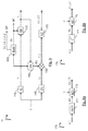
- Fig. 7a -b show schematically a diagram of the steps of a method of encoding a color picture in accordance with two particular different embodiments regarding the one of Fig. 2 .
- At least two distinct first SDR color pictures I 1st_SDR1 and I 1st_SDR2 are respectively obtained from at least two distinct color-graded versions of said HDR color picture I HDR by using respectively distinct color gamuts, for example the BT.2020 or BT.709 gamuts, where the gamut BT.2020 defines a color space for UHDTV, whereas BT.709, defines a smaller color gamut for HDTV.
- said HDR color picture I HDR is represented in the BT.2020 gamut.
- two first SDR color pictures I 1st_SDR1 and I 1st_SDR2 are respectively obtained from two distinct color-graded versions of said HDR color picture I HDR by using respectively distinct color gamuts.
- a first grading (121) is performed on said HDR color picture I HDR , and is consistent with the BT.2020 gamut, delivering a first SDR color picture I 1st_SDR1 consistent with the BT.2020.
- a second grading (122) is performed on said HDR color picture I HDR , and is consistent with the BT.709 gamut, delivering a first SDR color picture I 1st_SDR1 consistent with the BT.709 gamut.
- Two pieces of color remapping information are respectively determined (111, 112) and then transmitted (1020, 1030), on the one hand, one piece of color remapping information CRi 1 from said second SDR color picture I 2nd _ SDR (delivered by said mapping (12), as previously described, of the HDR color picture) to said first SDR color picture I 1st _ SDR1 consistent with the BT.2020 gamut, and on the other hand, one other piece of color remapping information CRi 2 from said second SDR color picture I 2nd _ SDR to said first SDR color picture I 1st_SDR2 consistent with the BT.709 gamut.
- said piece of color remapping information CRi 1 links said second SDR color picture I 2nd_SDR with said first SDR color picture I 1st_SDR1 , both pictures being consistent with the BT.2020 gamut.
- the other piece of color remapping information CRi 2 links said second SDR color picture I 2nd_SDR with said first SDR color picture I 1st_SDR2 , said second SDR color picture I 2nd_SDR being consistent with the BT.2020 gamut whereas said first SDR color picture I 1st_SDR2 being consistent with the BT.709 gamut.
- Such embodiment permits to deal with the scenario where there is a coexistence of BT2020 HDR videos with BT2020/BT709 SDR videos. Indeed, today current infrastructures support only the BT709 gamut but UHDTV will migrate to the huge BT2020 gamut.
- the P3 gamut is larger than the BT709 gamut but smaller than the BT2020 gamut.
- a 48 nits grading is used for cinematographic projections in theater.
- said two pieces of color remapping are each transmitted (1020, 1030) in a same dedicated transmission channel distinct from the channel used for transmitting 1010 said second SDR color picture I 2nd_SDR , or, according to another variant, respectively transmitted (1020, 1030) in two dedicated and separated transmission channels distinct from the channel used for transmitting 1010 said second SDR color picture I 2nd_SDR .
- FIG. 7b differs from the one in Fig. 7a in that said second SDR color picture I 2nd_SDR is delivered by an invertible gamut mapping (1200) between said distinct color gamuts, said invertible gamut mapping (1200), being performed after said mapping (12) and before said encoding (13), and mapping one (BT.2020) of said distinct color gamuts onto the other (BT.709).
- said second SDR color picture I 2nd_SDR is consistent with the BT.709 gamut
- said HDR color picture I HDR is consistent with the BT.2020 gamut
- said invertible gamut mapping BT_GM) (1200) is performed to map said BT.2020 gamut to the BT.709 gamut (the BT2020 saturation (2020) is compressed toward the BT709 saturation (709) as illustrated by Fig. 1 ), delivering said second SDR color picture I 2nd_SDR consistent with the BT.709 gamut.
- two pieces of color remapping information are respectively determined (1110, 1120) and then transmitted (1020, 1030), on the one hand, one piece of color remapping information CRi 1 from a third SDR color picture I 3rd_SDR delivered by an inverse gamut mapping operation I_BT_GM (gamut de-mapping) (103) performed after said invertible gamut mapping (1200), and consistent with the BT.2020 gamut to said first SDR color picture I 1st_SDR1 consistent with the BT.2020 gamut, and on the other hand, one other piece of color remapping information CRi 2 from said second SDR color picture I 2nd_SDR consistent with the BT.709 gamut to said first SDR color picture I 1st_SDR2 consistent with the BT.709 gamut.
- I_BT_GM gamut de-mapping
- said piece of color remapping information CRi 1 links said third SDR color picture I 3rd_SDR with said first SDR color picture I 1st_SDR1 , both pictures being consistent with the BT.2020 gamut.
- the other piece of color remapping information CRi 2 links said second SDR color picture I 2nd_SDR with said first SDR color picture I 1st_sDR2 , both pictures being consistent with the BT.709 gamut.
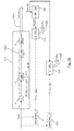
- Fig. 8a shows schematically a diagram of the steps of a method of decoding a HDR color picture I HDR and at least one first SDR color picture I 1st_SDR_d , from a second SDR color picture of a received bitstream B R in accordance with an embodiment of the disclosure.
- said bitstream B R is obtained, using the encoding method as previously described in relation with Fig. 2-7 , from a High Dynamic Range (HDR) color picture and at least one first Standard Dynamic Range (SDR) color picture, said bitstream B R comprising at least one encoded second Standard Dynamic Range (SDR) color picture I 2nd_SDR_c and also at least one piece of color remapping information CRi associated with said at least one encoded second Standard Dynamic Range (SDR) color picture I 2nd_SDR_C , said at least one piece of color remapping information being used to obtain an approximation of said at least one first Standard Dynamic Range (SDR) color picture from said encoded second Standard Dynamic Range (SDR) color picture I 2nd_SDR_C .
- HDR High Dynamic Range
- SDR Standard Dynamic Range
- a second encoded SDR color picture I 2nd_SDR_C is obtained and then decoded thanks to the decoding module 201 delivering a second decoded SDR color picture I 2nd_SDR_d .
- At least one piece of color remapping information CRi associated with said encoded second SDR color picture I 2nd_SDR_C is obtained (202) from said received bitstream B R and then applied (203) to said second SDR color picture I 2nd_SDR_d delivering an approximation I' 1st_SDR_d of said at least one first SDR color picture I 1st_SDR_d .
- Said at least one piece of color remapping information CRi associated with said encoded second SDR color picture I 2nd_SDR_C is for example inserted in a SEI message of said received bitstream B R , and at the decoding provides information to enable remapping of the reconstructed color samples (i.e. a CRi adaptation) of the decoded second SDR color picture I 2nd_SDR to obtain an approximation I' 1st_SDR_d of said at least one first SDR color picture I 1st_SDR_d , which has been obtained, during the encoding (as illustrated in Fig. 8a ), from a color-graded version of the source HDR color picture I HDR used during encoding.
- a same video content can be delivered on several types of equipment, for example one HDR display, an UHDTV with a set-top-box suitable for performing a CRi adaptation or other existing UHDTVs and STBs without any additional processing in existing equipment.
- the decoder will be able to reconstruct at least three items:
- said color remapping information may be applied directly to the decoded samples value of said decoded second SDR color picture I 2nd_SDR_d regardless of whether they are in the luma and chroma domain or the RGB domain.
- the color remapping model used in the color remapping information SEI message is composed of a first piece-wise linear function applied to each color component (specified by the "pre” set of syntax elements herein), a three-by-three matrix applied to the three color components, and a second piece-wise linear function applied to each color component (specified by the "post” set of syntax elements specified in the section D.3.32 entitled " Colour remapping information SEI message semantics" of the standard ITU-T H.265 (10/2014) Series H: Audiovisual and Multimedia Systems ).
- said received bitstream B R comprises at least said second encoded SDR color picture I 2nd_SDR_c and a piece of color remapping information associated with said second encoded SDR color picture I 2nd_SDR_C .
- said piece of color remapping information CRi is obtained 202 using said receiving antenna 20 from a dedicated transmission channel distinct from the channel used for transmitting 1010 said second SDR color picture I 2nd_SDR_C .
- said decoding module 201 comprises a decoder DEC for obtaining (21) a luminance component L" and two chrominance components C"1, C"2 either from a local or remote memory or by decoding at least partially a bitstream F.
- said decoding module 201 further comprises a module IGM for obtaining (22) a final luminance component L and two final chrominance components C1, C2 from said luminance L" and chrominance C"1, C"2 components by applying an inverse mapping on the colors obtained from said luminance L" and chrominance C"1, C"2 components.
- said module IGM permits to transform an SDR color picture into a corresponding HDR picture, and is the inverse operation of the HDR-to-SDR mapping (12) performed during the encoding as illustrated in Fig 2-7 .
- a module INVC obtains at least one color component Ec of the HDR color picture I HDR_d to be decoded from said final luminance L component and said two final chrominance C1, C2 components.
- the decoded picture being obtained by combining together said at least one color component Ec.
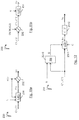
- Fig. 8b -c show schematically a diagram of the steps of a method of decoding a color picture in accordance with two other different embodiments regarding the one of Fig. 8a .
- At least two distinct pieces of color remapping information CRi 1 and CRi 2 associated with said second encoded SDR color picture I 2nd_SDR_C are obtained (2021, 2022) from said received bitstream B R , and then applied (204, 205) to the second decoded SDR color picture I 2nd_SDR delivered by said decoding module 201 delivering two distinct approximations I' 1st_SDR1_d and I' 1st_SDR2_d of at least two distinct first SDR color pictures, obtained, during encoding as illustrated by Fig.
- the term "approximation” is used since, the color remapping information helps producing an SDR picture that is visually close to the first SDR color picture, but does not guarantee any distance target, in terms of mathematical distortion between two pictures.
- said decoded SDR color picture I 2nd_SDR_d is consistent with the BT.2020 gamut, and permits to obtain the decoded HDR color picture I HDR_d , consistent with the BT.2020 gamut, delivered by said modules IGM and INVC already presented in relation with Fig. 8a .
- Said decoded SDR color picture I 2nd_SDR_d consistent with the BT.2020 gamut, would be viewable but its display would not be acceptable from the point of view of the Colorist or of the Director of Photography.
- a first color adaptation of said decoded SDR color picture I 2nd_SDR_d is performed (204) delivering said approximations I' 1st_SDR1_d consistent with the BT.2020 gamut and conform to the Colorist intent when considering said BT.2020 gamut.
- a second color adaptation of said decoded SDR color picture I 2nd_SDR is performed (205) delivering said approximations I' 1st_SDR2_d consistent with the BT.709 gamut.
- said second encoded SDR color picture I 2nd_SDR_C and the two associated distinct pieces of color remapping information CRi 1 and CRi 2 the decoder will be able to reconstruct at least four items:
- said two pieces of color remapping CRi 1 and CRi 2 are obtained 202 using said receiving antenna 20 from a dedicated transmission channel distinct from the channel used for transmitting 1010 said second SDR color picture I 2nd_SDR_C .
- FIG. 8c differs from the one in Fig. 8b in that said decoded SDR color picture I 2nd_SDR_d is consistent with a gamut different from the gamut which is compatible for example with the HDR display device of a user.
- said decoded SDR color picture I 2nd_SDR_d is consistent with the BT.709 gamut, whereas the HDR display device is only compatible with the BT.2020 gamut.
- Said decoded SDR color picture I 2nd_SDR_d consistent with the BT.709 gamut, would be viewable but its display would not be acceptable from the point of view of the Colorist or of the Director of Photography.
- a supplemental inverse operation I_BT_GM (gamut de-mapping) (206) of an invertible gamut mapping is applied on the result delivered by said modules IGM and INVC already presented in relation with Fig. 8a .
- Said inverse operation I_BT_GM (gamut de-mapping) (206) is inverse operation of the invertible gamut mapping (1200), which has been performed during encoding, as illustrated by Fig.7b .
- a first color adaptation of said decoded SDR color picture I 2nd_SDR_d is performed (2040) delivering said approximations I' 1st_SDR1_d consistent with the BT.709 gamut and conform to the Colorist intent when considering said gamut BT.709.
- Equation (J) is considered as being an inverse mapping applies on the colors obtained from the luminance L" and chrominance C"1, C"2 components. Equation (J) is directly obtained from equation (A) that is considered as being a color mapping.
- the values of the final luminance component L are always higher than the values of the luminance component L":
- L L ⁇ + max m C 1 ⁇ + n C 2 ⁇
- This embodiment is advantageous because it ensures that the luminance component L does not exceed a potential clipping value that is usually used by the decoder to define a luminance peak.
- a luminance peak is required by a decoder and when the luminance component L is given by equation (J), the luminance component L is clipped introducing some artefacts.
- the modulation value Ba and/or the coefficients m and n are obtained from a remote or local memory such a Look-Up-Table, or from a bitstream BF as illustrated in Fig. 9 .
- the factor ⁇ -1 ( Ba , L ( i )) is obtained from a Look-Up-Table (LUT) for a specific modulation value Ba and a specific value L(i) of the final luminance component L.
- LUT Look-Up-Table
- a specific factor ⁇ -1 (Ba, L(i)) is stored in a LUT for each specific modulation value Ba.
- the factor ⁇ -1 ( Ba,L(i )) for a specific modulation value Ba is obtained for a value of a pixel of the final luminance component L by interpolating the luminance peaks between the multiple luminance peaks for which LUT are stored.
- the non-linear function f -1 is the inverse of the non-linear function f (step 130).
- the embodiments of the function f -1 are defined according to the embodiments of the function f.
- the parameters of the non-linear function f -1 (such as a, b, c or y) and/or the information data Inf is (are) obtained from a local or remote memory (for example a Look-Up-Table) and/or from a bitstream BF as illustrated in Fig. 10 .
- the non-linear function f -1 is the inverse of a gamma function.
- Y 1 L 1 / ⁇ B
- Y 1 equals Y or Y/Ba according to the embodiments of eq. (A3) or (A4)
- B is a constant value
- ⁇ is a parameter (real value strictly below 1).
- the non-linear function f -1 is the inverse of a S-Log function.
- the non-linear function f is the inverse of either a gamma correction or a SLog correction according to the pixel values of the component Y. This is indicated by the information data Inf.
- a module ILC obtains at least one color component Ec from the first component Y, the two chrominance component C1, C2, and from a factor r(L) that depends on the luminance component L.
- the decoded color picture is then obtained by combining together said at least one color component Ec.
- each intermediate color component E'c the intermediate components Dc are related to the component Y, the two chrominance components C1, C2 and the factor r(L):
- EOTF Electro-Optical Trans Function
- OETF( E c ) D c
- ⁇ i are constants depending on the matrix A
- L i are linear functions also depending on the matrix A.
- a module ILEC obtains three intermediate color component E'c from the first component Y, the two chrominance component C1, C2 and the factor r(L) as above explained.
- step 231 before step 232 is the inverse of the order step 150 followed by step 170 of the encoding method.
- the OEFT is a square root function and the EOTF is then a square function.
- the OEFT is a cubic root function and the EOTF is then a cubic function.
- step 232 two intermediate components C'1 and C'2 are obtained by scaling the two chrominance components C1 and C2 by the factor OEFT(r(L(i))) where OETF is the function used in step 171 in Fig.
- a module ILEC obtains the three color components Ec from the first component Y and the two intermediate chrominance components C'1, C'2 as above explained.
- the OEFT is a square root function and the EOTF is then a square function.
- Equation (A14) is a second order equation that may be solved analytically.
- This analytic solution leads to a specific embodiment of the step 231 as illustrated in Fig. 12 .
- This embodiment is advantageous because it allows an analytic expression of the EOTF (inverse of the OETF) and thus of the decoded components of the picture.
- the EOTF is then the square function that is a low complexity process at the decoding side.
- the matrix A determines the transform of said HDR color picture I HDR to be encoded from the color space (E1, E2, E3), in which the pixel values of the picture to be encoded are represented, to the color space (Y, C1, C2).
- Such a matrix depends on the gamut of the color picture to be encoded.
- the OEFT is a cube root function and the EOTF is then a cubic function.
- the EOTF is then a cubic function thus leading to an equation (14) on F 1 being a more complex third order equation which can be solved analytically by the so-called Cardano's method.
- the decoder DEC is configured to decode data, which have been encoded by the encoder ENC.
- the encoder ENC (and decoder DEC) is not limited to a specific encoder (decoder) but when an entropy encoder (decoder) is required, an entropy encoder such as a Huffmann coder, an arithmetic coder or a context adaptive coder like Cabac used in H264/AVC or HEVC is advantageous.
- the encoders ENC (and decoder DEC) is not limited to a specific encoder which may be, for example, an frame/video legacy coder with loss like JPEG, JPEG2000, MPEG2, H264/AVC or HEVC.
- the modules are functional units, which may or not be in relation with distinguishable physical units. For example, these modules or some of them may be brought together in a unique component or circuit, or contribute to functionalities of a software. A contrario, some modules may potentially be composed of separate physical entities.
- the apparatus which are compatible with the disclosure are implemented using either pure hardware, for example using dedicated hardware such ASIC or FPGA or VLSI, respectively «Application Specific Integrated Circuit » « Field-Programmable Gate Array » « Very Large Scale Integration » or from several integrated electronic components embedded in a device or from a blend of hardware and software components.
- Fig. 13 represents an exemplary architecture of a device 1300 which may be configured to implement an encoding method described in relation with Fig. 1-7 or a decoding method in relation with Fig. 8-12 .
- Device 1300 comprises following elements that are linked together by a data and address bus 1301:
- the battery 1306 is external to the device.
- the word « register used in the specification can correspond to area of small capacity (some bits) or to very large area (e.g. a whole program or large amount of received or decoded data).
- ROM 1303 comprises at least a program and parameters. Algorithm of the methods according to the disclosure is stored in the ROM 1303. When switched on, the CPU 1302 uploads the program in the RAM and executes the corresponding instructions.
- RAM 1304 comprises, in a register, the program executed by the CPU 1302 and uploaded after switch on of the device 1300, input data in a register, intermediate data in different states of the method in a register, and other variables used for the execution of the method in a register.
- the implementations described herein may be implemented in, for example, a method or a process, an apparatus, a software program, a data stream, or a signal. Even if only discussed in the context of a single form of implementation (for example, discussed only as a method or a device), the implementation of features discussed may also be implemented in other forms (for example a program).
- An apparatus may be implemented in, for example, appropriate hardware, software, and firmware.
- the methods may be implemented in, for example, an apparatus such as, for example, a processor, which refers to processing devices in general, including, for example, a computer, a microprocessor, an integrated circuit, or a programmable logic device. Processors also include communication devices, such as, for example, computers, cell phones, portable/personal digital assistants ("PDAs”), and other devices that facilitate communication of information between end-users.
- PDAs portable/personal digital assistants
- said HDR color picture I HDR is obtained from a source.
- the source belongs to a set comprising:
- the decoded picture is sent to a destination; specifically, the destination belongs to a set comprising:
- bitstream BF and/or F are sent to a destination.
- bitstream F and BF or both bitstreams F and BF are stored in a local or remote memory, e.g. a video memory (1304) or a RAM (1304), a hard disk (1303).
- a storage interface e.g. an interface with a mass storage, a flash memory, ROM, an optical disc or a magnetic support and/or transmitted over a communication interface (1305), e.g. an interface to a point to point link, a communication bus, a point to multipoint link or a broadcast network.
- the bitstream BF and/or F is obtained from a source.
- the bitstream is read from a local memory, e.g. a video memory (1304), a RAM (1304), a ROM (1303), a flash memory (1303) or a hard disk (1303).
- the bitstream is received from a storage interface, e.g. an interface with a mass storage, a RAM, a ROM, a flash memory, an optical disc or a magnetic support and/or received from a communication interface (1305), e.g. an interface to a point to point link, a bus, a point to multipoint link or a broadcast network.
- device 1300 being configured to implement an encoding method described in relation with Fig. 2-7 , belongs to a set comprising:
- device 1300 being configured to implement a decoding method described in relation with Fig. 8-12 , belongs to a set comprising:
- the device A comprises means which are configured to implement a method for encoding an picture as described in relation with the Fig. 2-7 and the device B comprises means which are configured to implement a method for decoding as described in relation with Fig. 8-12 , the device A of figure 2 communicating with the device B of Fig. 8a according to a first embodiment, and the device A of Fig. 7a and 7b communicating respectively with the device B of Fig. 8b and 8c according to a second and a third embodiment respectively.
- the network is a broadcast network, adapted to broadcast still pictures or video pictures from device A to decoding devices including the device B.
- Implementations of the various processes and features described herein may be embodied in a variety of different equipment or applications.
- Examples of such equipment include an encoder, a decoder, a post-processor processing output from a decoder, a pre-processor providing input to an encoder, a video coder, a video decoder, a video codec, a web server, a set-top box, a laptop, a personal computer, a cell phone, a PDA, and any other device for processing a picture or a video or other communication devices.
- the equipment may be mobile and even installed in a mobile vehicle.
- a computer readable storage medium can take the form of a computer readable program product embodied in one or more computer readable medium(s) and having computer readable program code embodied thereon that is executable by a computer.
- a computer readable storage medium as used herein is considered a non-transitory storage medium given the inherent capability to store the information therein as well as the inherent capability to provide retrieval of the information therefrom.
- a computer readable storage medium can be, for example, but is not limited to, an electronic, magnetic, optical, electromagnetic, infrared, or semiconductor system, apparatus, or device, or any suitable combination of the foregoing. It is to be appreciated that the following, while providing more specific examples of computer readable storage mediums to which the present principles can be applied, is merely an illustrative and not exhaustive listing as is readily appreciated by one of ordinary skill in the art: a portable computer diskette; a hard disk; a read-only memory (ROM); an erasable programmable read-only memory (EPROM or Flash memory); a portable compact disc read-only memory (CD-ROM); an optical storage device; a magnetic storage device; or any suitable combination of the foregoing.
- the instructions may form an application program tangibly embodied on a processor-readable medium.
- Instructions may be, for example, in hardware, firmware, software, or a combination. Instructions may be found in, for example, an operating system, a separate application, or a combination of the two.
- a processor may be characterized, therefore, as, for example, both a device configured to carry out a process and a device that includes a processor-readable medium (such as a storage device) having instructions for carrying out a process. Further, a processor-readable medium may store, in addition to or in lieu of instructions, data values produced by an implementation.
- implementations may produce a variety of signals formatted to carry information that may be, for example, stored or transmitted.
- the information may include, for example, instructions for performing a method, or data produced by one of the described implementations.
- a signal may be formatted to carry as data the rules for writing or reading the syntax of a described embodiment, or to carry as data the actual syntax-values written by a described embodiment.
- Such a signal may be formatted, for example, as an electromagnetic wave (for example, using a radio frequency portion of spectrum) or as a baseband signal.
- the formatting may include, for example, encoding a data stream and modulating a carrier with the encoded data stream.
- the information that the signal carries may be, for example, analog or digital information.
- the signal may be transmitted over a variety of different wired or wireless links, as is known.
- the signal may be stored on a processor-readable medium.
Landscapes
- Engineering & Computer Science (AREA)
- Multimedia (AREA)
- Signal Processing (AREA)
- Physics & Mathematics (AREA)
- General Physics & Mathematics (AREA)
- Theoretical Computer Science (AREA)
- Compression Or Coding Systems Of Tv Signals (AREA)
- Color Television Systems (AREA)
- Image Processing (AREA)
- Processing Of Color Television Signals (AREA)
Priority Applications (13)
| Application Number | Priority Date | Filing Date | Title |
|---|---|---|---|
| EP15306042.1A EP3113495A1 (de) | 2015-06-30 | 2015-06-30 | Verfahren und vorrichtungen zur codierung und decodierung eines hdr farbbildes |
| TW105119815A TW201701665A (zh) | 2015-06-30 | 2016-06-24 | 編碼及解碼彩色圖像之方法及裝置 |
| BR112017028459A BR112017028459A2 (pt) | 2015-06-30 | 2016-06-27 | métodos e dispositivos para a codificação e decodificação de uma imagem colorida hdr |
| JP2017567637A JP2018525883A (ja) | 2015-06-30 | 2016-06-27 | カラー・ピクチャを符号化および復号する方法およびデバイス |
| CA2990988A CA2990988A1 (en) | 2015-06-30 | 2016-06-27 | Methods and devices for encoding and decoding a hdr color picture |
| MX2017016832A MX2017016832A (es) | 2015-06-30 | 2016-06-27 | Metodos y dispositivos para codificar y decodificar una imagen de color hdr. |
| US15/741,096 US20180352257A1 (en) | 2015-06-30 | 2016-06-27 | Methods and devices for encoding and decoding a color picture |
| KR1020187002625A KR20180021869A (ko) | 2015-06-30 | 2016-06-27 | Hdr 컬러 픽처를 인코딩 및 디코딩하기 위한 방법 및 디바이스 |
| RU2018102703A RU2710291C2 (ru) | 2015-06-30 | 2016-06-27 | Способы и устройства для кодирования и декодирования цветного изображения hdr |
| EP16793759.8A EP3329677A1 (de) | 2015-06-30 | 2016-06-27 | Verfahren und vorrichtungen zur codierung und decodierung eines hdr farbbildes |
| CN201680044781.1A CN107852503A (zh) | 2015-06-30 | 2016-06-27 | 用于对彩色图片进行编码和解码的方法和设备 |
| PCT/EP2016/064839 WO2017001331A1 (en) | 2015-06-30 | 2016-06-27 | Methods and devices for encoding and decoding a hdr color picture |
| ZA2017/08433A ZA201708433B (en) | 2015-06-30 | 2017-12-12 | Methods and devices for encoding and decoding a hdr color picture |
Applications Claiming Priority (1)
| Application Number | Priority Date | Filing Date | Title |
|---|---|---|---|
| EP15306042.1A EP3113495A1 (de) | 2015-06-30 | 2015-06-30 | Verfahren und vorrichtungen zur codierung und decodierung eines hdr farbbildes |
Publications (1)
| Publication Number | Publication Date |
|---|---|
| EP3113495A1 true EP3113495A1 (de) | 2017-01-04 |
Family
ID=53724152
Family Applications (2)
| Application Number | Title | Priority Date | Filing Date |
|---|---|---|---|
| EP15306042.1A Withdrawn EP3113495A1 (de) | 2015-06-30 | 2015-06-30 | Verfahren und vorrichtungen zur codierung und decodierung eines hdr farbbildes |
| EP16793759.8A Withdrawn EP3329677A1 (de) | 2015-06-30 | 2016-06-27 | Verfahren und vorrichtungen zur codierung und decodierung eines hdr farbbildes |
Family Applications After (1)
| Application Number | Title | Priority Date | Filing Date |
|---|---|---|---|
| EP16793759.8A Withdrawn EP3329677A1 (de) | 2015-06-30 | 2016-06-27 | Verfahren und vorrichtungen zur codierung und decodierung eines hdr farbbildes |
Country Status (12)
| Country | Link |
|---|---|
| US (1) | US20180352257A1 (de) |
| EP (2) | EP3113495A1 (de) |
| JP (1) | JP2018525883A (de) |
| KR (1) | KR20180021869A (de) |
| CN (1) | CN107852503A (de) |
| BR (1) | BR112017028459A2 (de) |
| CA (1) | CA2990988A1 (de) |
| MX (1) | MX2017016832A (de) |
| RU (1) | RU2710291C2 (de) |
| TW (1) | TW201701665A (de) |
| WO (1) | WO2017001331A1 (de) |
| ZA (1) | ZA201708433B (de) |
Cited By (3)
| Publication number | Priority date | Publication date | Assignee | Title |
|---|---|---|---|---|
| CN111434113A (zh) * | 2017-11-30 | 2020-07-17 | 交互数字Vc控股公司 | 用于高动态范围重建的饱和控制 |
| CN114338947A (zh) * | 2017-03-31 | 2022-04-12 | 交互数字Vc控股公司 | 用于色域映射的方法和设备 |
| CN111434113B (zh) * | 2017-11-30 | 2024-06-07 | 交互数字Vc控股公司 | 用于高动态范围重建的饱和控制 |
Families Citing this family (16)
| Publication number | Priority date | Publication date | Assignee | Title |
|---|---|---|---|---|
| US10609395B2 (en) * | 2015-07-28 | 2020-03-31 | Vid Scale, Inc. | High dynamic range video coding architectures with multiple operating modes |
| US10687080B2 (en) * | 2015-08-28 | 2020-06-16 | Arris Enterprises Llc | Color volume transforms in coding of high dynamic range and wide color gamut sequences |
| US10720091B2 (en) * | 2017-02-16 | 2020-07-21 | Microsoft Technology Licensing, Llc | Content mastering with an energy-preserving bloom operator during playback of high dynamic range video |
| EP3367659A1 (de) * | 2017-02-28 | 2018-08-29 | Thomson Licensing | Farbtonbereichsumsetzung für farbtonänderung |
| US10574959B2 (en) * | 2017-07-05 | 2020-02-25 | Qualcomm Incorporated | Color remapping for non-4:4:4 format video content |
| US10778978B2 (en) * | 2017-08-21 | 2020-09-15 | Qualcomm Incorporated | System and method of cross-component dynamic range adjustment (CC-DRA) in video coding |
| US10546554B2 (en) * | 2018-03-26 | 2020-01-28 | Dell Products, Lp | System and method for adaptive tone mapping for high dynamic ratio digital images |
| US10630867B2 (en) * | 2018-09-17 | 2020-04-21 | Samsung Electronics Co., Ltd. | Perceptual hue preserved color-gamut transferring in non-uniform CIE-1931 color space |
| JP7138935B2 (ja) * | 2018-10-19 | 2022-09-20 | 株式会社朋栄 | Hdr映像をsdr映像に変換するhdr広色域映像変換装置及びhdr広色域映像変換方法 |
| US11348553B2 (en) | 2019-02-11 | 2022-05-31 | Samsung Electronics Co., Ltd. | Color gamut mapping in the CIE 1931 color space |
| KR20210096281A (ko) | 2019-06-17 | 2021-08-04 | 엘지전자 주식회사 | 루마 맵핑 기반 비디오 또는 영상 코딩 |
| JP7479457B2 (ja) * | 2019-09-20 | 2024-05-08 | 北京字節跳動網絡技術有限公司 | ビデオ・データを処理する方法、装置及び記憶媒体 |
| EP3839876A1 (de) * | 2019-12-20 | 2021-06-23 | Fondation B-COM | Verfahren zur umwandlung eines bildes und entsprechende vorrichtung |
| CN115797152A (zh) * | 2021-09-10 | 2023-03-14 | 北京字跳网络技术有限公司 | 一种颜色映射色卡生成方法及装置 |
| US11587213B1 (en) | 2021-11-05 | 2023-02-21 | GM Cruise Holdings LLC. | Preserving dynamic range in images |
| CN115174881B (zh) * | 2022-07-15 | 2024-02-13 | 深圳市火乐科技发展有限公司 | 色域映射方法、装置、投影设备及存储介质 |
Family Cites Families (9)
| Publication number | Priority date | Publication date | Assignee | Title |
|---|---|---|---|---|
| WO2010105036A1 (en) * | 2009-03-13 | 2010-09-16 | Dolby Laboratories Licensing Corporation | Layered compression of high dynamic range, visual dynamic range, and wide color gamut video |
| CN102986214A (zh) * | 2010-07-06 | 2013-03-20 | 皇家飞利浦电子股份有限公司 | 从低动态范围图像生成高动态范围图像 |
| TWI521973B (zh) * | 2011-04-15 | 2016-02-11 | 杜比實驗室特許公司 | 高動態範圍影像的編碼、解碼及表示 |
| WO2012147018A2 (en) * | 2011-04-28 | 2012-11-01 | Koninklijke Philips Electronics N.V. | Apparatuses and methods for hdr image encoding and decoding |
| UA116082C2 (uk) * | 2011-09-27 | 2018-02-12 | Конінклійке Філіпс Н.В. | Пристрій та спосіб для перетворення динамічного діапазону зображень |
| CN103024300B (zh) * | 2012-12-25 | 2015-11-25 | 华为技术有限公司 | 一种高动态范围图像显示方法及装置 |
| CN106488246B (zh) * | 2013-06-17 | 2019-06-11 | 杜比实验室特许公司 | 用于增强动态范围信号的分层编码的自适应整形的方法 |
| CN103391435A (zh) * | 2013-07-02 | 2013-11-13 | 广东工业大学 | 一种兼容ldr的hdr图像编码方法及其解码方法 |
| JP6202330B2 (ja) * | 2013-10-15 | 2017-09-27 | ソニー株式会社 | 復号装置および復号方法、並びに符号化装置および符号化方法 |
-
2015
- 2015-06-30 EP EP15306042.1A patent/EP3113495A1/de not_active Withdrawn
-
2016
- 2016-06-24 TW TW105119815A patent/TW201701665A/zh unknown
- 2016-06-27 CN CN201680044781.1A patent/CN107852503A/zh active Pending
- 2016-06-27 WO PCT/EP2016/064839 patent/WO2017001331A1/en active Application Filing
- 2016-06-27 US US15/741,096 patent/US20180352257A1/en not_active Abandoned
- 2016-06-27 MX MX2017016832A patent/MX2017016832A/es unknown
- 2016-06-27 EP EP16793759.8A patent/EP3329677A1/de not_active Withdrawn
- 2016-06-27 JP JP2017567637A patent/JP2018525883A/ja active Pending
- 2016-06-27 KR KR1020187002625A patent/KR20180021869A/ko unknown
- 2016-06-27 RU RU2018102703A patent/RU2710291C2/ru active
- 2016-06-27 CA CA2990988A patent/CA2990988A1/en not_active Abandoned
- 2016-06-27 BR BR112017028459A patent/BR112017028459A2/pt not_active Application Discontinuation
-
2017
- 2017-12-12 ZA ZA2017/08433A patent/ZA201708433B/en unknown
Non-Patent Citations (7)
| Title |
|---|
| "High Efficiency Video Coding", SERIES H: AUDIOVISUAL AND MULTIMEDIA SYSTEMS, RECOMMENDATION ITU-T H.265, TELECOMMUNICATION STANDARDIZATION SECTOR OF ITU, October 2014 (2014-10-01) |
| ANDRIVON P ET AL: "AVC update with Colour Remapping Information SEI message", 111. MPEG MEETING; 6-2-2015 - 20-2-2015; GENEVA; (MOTION PICTURE EXPERT GROUP OR ISO/IEC JTC1/SC29/WG11),, no. m35665, 3 February 2015 (2015-02-03), XP030064033 * |
| LASSERRE S ET AL: "Single layer low-bit depth EDR video coding with SDR/HDR backward compatibilities", 111. MPEG MEETING; 6-2-2015 - 20-2-2015; GENEVA; (MOTION PICTURE EXPERT GROUP OR ISO/IEC JTC1/SC29/WG11),, no. m36083, 17 February 2015 (2015-02-17), XP030064451 * |
| LE LÉANNEC F ET AL: "Usage of modulation channel for high bit-depth signal encoding", 18. JCT-VC MEETING; 30-6-2014 - 9-7-2014; SAPPORO; (JOINT COLLABORATIVE TEAM ON VIDEO CODING OF ISO/IEC JTC1/SC29/WG11 AND ITU-T SG.16 ); URL: HTTP://WFTP3.ITU.INT/AV-ARCH/JCTVC-SITE/,, no. JCTVC-R0267, 26 June 2014 (2014-06-26), XP030116574 * |
| REC. ITU-R BT.2020-1, June 2014 (2014-06-01) |
| REC. ITU-R BT.709-5, April 2002 (2002-04-01) |
| SMPTE STANDARD: HIGH DYNAMIC RANGE ELECTRO-OPTICAL TRANSFER FUNCTION OF MASTERING REFERENCE DISPLAYS, SMPTE ST, 2014 |
Cited By (4)
| Publication number | Priority date | Publication date | Assignee | Title |
|---|---|---|---|---|
| CN114338947A (zh) * | 2017-03-31 | 2022-04-12 | 交互数字Vc控股公司 | 用于色域映射的方法和设备 |
| CN114338947B (zh) * | 2017-03-31 | 2024-04-02 | 交互数字Vc控股公司 | 用于色域映射的方法和设备 |
| CN111434113A (zh) * | 2017-11-30 | 2020-07-17 | 交互数字Vc控股公司 | 用于高动态范围重建的饱和控制 |
| CN111434113B (zh) * | 2017-11-30 | 2024-06-07 | 交互数字Vc控股公司 | 用于高动态范围重建的饱和控制 |
Also Published As
| Publication number | Publication date |
|---|---|
| RU2710291C2 (ru) | 2019-12-25 |
| RU2018102703A (ru) | 2019-07-31 |
| JP2018525883A (ja) | 2018-09-06 |
| BR112017028459A2 (pt) | 2018-08-28 |
| EP3329677A1 (de) | 2018-06-06 |
| MX2017016832A (es) | 2018-09-06 |
| US20180352257A1 (en) | 2018-12-06 |
| CN107852503A (zh) | 2018-03-27 |
| RU2018102703A3 (de) | 2019-07-31 |
| KR20180021869A (ko) | 2018-03-05 |
| TW201701665A (zh) | 2017-01-01 |
| CA2990988A1 (en) | 2017-01-05 |
| ZA201708433B (en) | 2019-04-24 |
| WO2017001331A1 (en) | 2017-01-05 |
Similar Documents
| Publication | Publication Date | Title |
|---|---|---|
| US11178412B2 (en) | Method and apparatus of encoding and decoding a color picture | |
| EP3113495A1 (de) | Verfahren und vorrichtungen zur codierung und decodierung eines hdr farbbildes | |
| US11006151B2 (en) | Method and device for encoding both a HDR picture and a SDR picture obtained from said HDR picture using color mapping functions | |
| EP3430807B1 (de) | Verfahren und vorrichtung zur kodierung eines bildes mit hohem dynamikbereich, zugehöriges dekodierungsverfahren und dekodierungsvorrichtung | |
| EP3251336B1 (de) | Verfahren und vorrichtung zur abstimmung von farben zwischen farbbildern mit unterschiedlichem dynamikbereich | |
| EP3051489A1 (de) | Verfahren und Vorrichtung zur Codierung und Decodierung eines Farbbildes | |
| US20180014024A1 (en) | Method and apparatus of encoding and decoding a color picture | |
| EP3051792A1 (de) | Verfahren und Vorrichtung zur Abstimmung von Farben zwischen Farbbildern mit unterschiedlichem Dynamikbereich | |
| EP3099073A1 (de) | Verfahren und vorrichtung zur codierung/decodierung eines hdr- und sdr-bildes in/aus einem skalierbaren bitstrom |
Legal Events
| Date | Code | Title | Description |
|---|---|---|---|
| PUAI | Public reference made under article 153(3) epc to a published international application that has entered the european phase |
Free format text: ORIGINAL CODE: 0009012 |
|
| AK | Designated contracting states |
Kind code of ref document: A1 Designated state(s): AL AT BE BG CH CY CZ DE DK EE ES FI FR GB GR HR HU IE IS IT LI LT LU LV MC MK MT NL NO PL PT RO RS SE SI SK SM TR |
|
| AX | Request for extension of the european patent |
Extension state: BA ME |
|
| STAA | Information on the status of an ep patent application or granted ep patent |
Free format text: STATUS: THE APPLICATION IS DEEMED TO BE WITHDRAWN |
|
| 18D | Application deemed to be withdrawn |
Effective date: 20170705 |