EP3113370B1 - Präventive automatische verstärkungsregelung zur interferenzabschwächung - Google Patents
Präventive automatische verstärkungsregelung zur interferenzabschwächung Download PDFInfo
- Publication number
- EP3113370B1 EP3113370B1 EP16171197.3A EP16171197A EP3113370B1 EP 3113370 B1 EP3113370 B1 EP 3113370B1 EP 16171197 A EP16171197 A EP 16171197A EP 3113370 B1 EP3113370 B1 EP 3113370B1
- Authority
- EP
- European Patent Office
- Prior art keywords
- signal
- agc
- preemptive
- communications link
- data packet
- Prior art date
- Legal status (The legal status is an assumption and is not a legal conclusion. Google has not performed a legal analysis and makes no representation as to the accuracy of the status listed.)
- Active
Links
Images


Classifications
-
- H—ELECTRICITY
- H04—ELECTRIC COMMUNICATION TECHNIQUE
- H04W—WIRELESS COMMUNICATION NETWORKS
- H04W52/00—Power management, e.g. Transmission Power Control [TPC] or power classes
- H04W52/04—Transmission power control [TPC]
- H04W52/52—Transmission power control [TPC] using AGC [Automatic Gain Control] circuits or amplifiers
-
- H—ELECTRICITY
- H04—ELECTRIC COMMUNICATION TECHNIQUE
- H04B—TRANSMISSION
- H04B1/00—Details of transmission systems, not covered by a single one of groups H04B3/00 - H04B13/00; Details of transmission systems not characterised by the medium used for transmission
- H04B1/06—Receivers
- H04B1/10—Means associated with receiver for limiting or suppressing noise or interference
- H04B1/1027—Means associated with receiver for limiting or suppressing noise or interference assessing signal quality or detecting noise/interference for the received signal
-
- H—ELECTRICITY
- H03—ELECTRONIC CIRCUITRY
- H03G—CONTROL OF AMPLIFICATION
- H03G3/00—Gain control in amplifiers or frequency changers
- H03G3/20—Automatic control
- H03G3/30—Automatic control in amplifiers having semiconductor devices
- H03G3/3052—Automatic control in amplifiers having semiconductor devices in bandpass amplifiers (H.F. or I.F.) or in frequency-changers used in a (super)heterodyne receiver
-
- H—ELECTRICITY
- H03—ELECTRONIC CIRCUITRY
- H03G—CONTROL OF AMPLIFICATION
- H03G3/00—Gain control in amplifiers or frequency changers
- H03G3/20—Automatic control
- H03G3/30—Automatic control in amplifiers having semiconductor devices
- H03G3/3089—Control of digital or coded signals
-
- H—ELECTRICITY
- H04—ELECTRIC COMMUNICATION TECHNIQUE
- H04B—TRANSMISSION
- H04B1/00—Details of transmission systems, not covered by a single one of groups H04B3/00 - H04B13/00; Details of transmission systems not characterised by the medium used for transmission
- H04B1/06—Receivers
- H04B1/10—Means associated with receiver for limiting or suppressing noise or interference
- H04B1/1027—Means associated with receiver for limiting or suppressing noise or interference assessing signal quality or detecting noise/interference for the received signal
- H04B1/1036—Means associated with receiver for limiting or suppressing noise or interference assessing signal quality or detecting noise/interference for the received signal with automatic suppression of narrow band noise or interference, e.g. by using tuneable notch filters
-
- H—ELECTRICITY
- H04—ELECTRIC COMMUNICATION TECHNIQUE
- H04B—TRANSMISSION
- H04B1/00—Details of transmission systems, not covered by a single one of groups H04B3/00 - H04B13/00; Details of transmission systems not characterised by the medium used for transmission
- H04B1/06—Receivers
- H04B1/10—Means associated with receiver for limiting or suppressing noise or interference
- H04B1/12—Neutralising, balancing, or compensation arrangements
- H04B1/123—Neutralising, balancing, or compensation arrangements using adaptive balancing or compensation means
-
- H—ELECTRICITY
- H04—ELECTRIC COMMUNICATION TECHNIQUE
- H04W—WIRELESS COMMUNICATION NETWORKS
- H04W24/00—Supervisory, monitoring or testing arrangements
- H04W24/08—Testing, supervising or monitoring using real traffic
-
- H—ELECTRICITY
- H04—ELECTRIC COMMUNICATION TECHNIQUE
- H04W—WIRELESS COMMUNICATION NETWORKS
- H04W4/00—Services specially adapted for wireless communication networks; Facilities therefor
- H04W4/80—Services using short range communication, e.g. near-field communication [NFC], radio-frequency identification [RFID] or low energy communication
Definitions
- wireless communication receivers in portable devices may include an automatic gain control (AGC) scheme that sets an optimal receiver gain setting of the portable device.
- AGC automatic gain control
- the AGC may maximize the dynamic receiver range of the portable device by amplifying the received signal to ensure that the signal-to-quantization-noise ratio (quantization noise is introduced by the A/D converters) is negligible.
- the AGC amplifies the received signal to ensure that the amplified signal is low enough that it is not clipped i.e., truncated due to signal being outside of an A/D converter.
- the AGC in the portable device may sample the total wide-band energy of the received signal at the time of received signal's preamble and sets the receiver gain adjustment accordingly. In this manner, saturation of the received signal is prevented especially when the desired signals are received in the presence of same-band or adjacent-band transmissions from collocated transmitting components or devices.
- the collocated core or transmitting components start their transmission after the AGC gain has been set (i.e., based solely on the desired, interference-free signal)
- the total received signal may be too strong, given the current AGC gain, and the receiver will be saturated or blocked. Consequently, the desired packet cannot be decoded and will be lost or corrupted.
- WO 2008/145800 A1 describes a technique for interference mitigation.
- An automatic gain control is configured to control the gain of a received wireless signal. The gain of the received signal is locked based on the observed interference to a level which avoids clipping of the received signal containing both the wanted signal and the interference during the time period of interference.
- a technology for implementing a preemptive - automatic gain control (AGC) system that mitigates a collocated or external interfering signal in a receiver of a portable device.
- the receiver of the portable device receives and processes a data packet of a first radio frequency (RF) signal that includes a Bluetooth (BT) signal, a Wi-Fi signal, a near field communications (NFC), 3G, 4G, or the like.
- RF radio frequency
- BT Bluetooth
- NFC near field communications
- 3G, 4G 3G, 4G, or the like.
- the second RF signal may include an interfering Bluetooth (BT) uplink transmission, a near field communications (NFC) transmission signal, a Wi-Fi transmission signal, 3G or 4G uplink transmission, an LTE signal, or the like.
- the detection of the second RF signal includes receiving or measuring in real-time an information of the second RF signal.
- the information includes an occurrence frequency, an amount of transmitting power, a transmitting time, and a period of transmission of the second RF signal.
- a gain setting of an enabled preemptive - AGC system is adjusted to generate an interference-free first RF signal.
- a received signal strength indicator (RSSI) of the interference-free first RF signal is measured and compared to a minimum detectable signal (MDS) threshold so as not to compromise a signal strength quality of the receiver.
- MDS minimum detectable signal
- the MDS threshold is utilized to make sure that the receiver's signal strength, which corresponds to the adjusted setting of the enabled preemptive - AGC system, is enough to maintain quality in the receiver's function to receive and process data packets.
- the enabling of the preemptive - AGC system is maintained. Otherwise, the preemptive - AGC system is disabled and an AGC mode is utilized instead in the receiving and processing of the first RF signal.
- FIG. 1 is an example scenario 100 that utilizes a preemptive - AGC system or component to mitigate interference or harmonic spurs in a receiver circuitry or system of a portable device.
- the scenario 100 shows a portable device 102 with an antenna 104, and another portable device 106 with an antenna 108.
- a first RF signal includes data packets from the Bluetooth (BT) signal, Wi-Fi signal, NFC signal, 3G signal, 4G signal, or the like, that are currently being processed by the receiver circuitry (not shown) of the portable device 102.
- a second RF signal includes an RF signal from a collocated or external BT uplink transmission, NFC transmission signal, Wi-Fi transmission signal, 3G or 4G uplink transmission, LTE signal, or the like, that may cause corruption or interference in the processing of the data packets of the first RF signal.
- the portable devices 102 or 106 may include, but is not limited to, a tablet computer, a netbook, a notebook computer, a laptop computer, mobile phone, a cellular phone, a smartphone, a personal digital assistant, a multimedia playback device, a digital music player, a digital video player, a navigational device, a digital camera, and the like.
- the portable device 102 may engage in data communication with the other portable device 106 through the use of the first RF signal such as the BT signal. While the portable device 102 is receiving and processing data packets through the BT signal, the second RF signal such as the Wi-Fi transmission signal, BT uplink transmission signal, or the like, may be detected by the receiver circuitry of the portable device 102.
- the second RF signal in this example, may be generated within the same portable device 102 (i.e., collocated), or may be received from the portable device 106 (i.e., external).
- the detection of the second RF signal includes receiving or measuring in real-time an information (not shown) of the second RF signal.
- the information includes an amount of transmitting power and a transmitting time period of the second RF signal.
- the information may include an occurrence frequency of the second RF signal.
- a preemptive - AGC component (not shown) of the portable device 102 is enabled and its gain setting is adjusted to generate an interference-free first RF signal.
- a RSSI of the interference-free first RF signal is measured and compared by the receiver circuitry of the portable device 102 to a minimum detectable signal (MDS) threshold so as not to compromise a signal strength quality of the receiver circuitry. That is, the signal strength for the adjusted gain setting of the enabled preemptive - AGC system of the receiver circuitry is not so low such that the portable device 102 may no longer engage in data communication with the portable device 106.
- MDS minimum detectable signal
- FIG. 2 is an example timeline 200 showing an overlap between the first and second RF signals as described in accordance with implementations described herein.
- the timeline 200 includes a first RF signal 202 that may be received and processed by the portable device 102, and a collocated or external second RF signal 204 that may interfere with the processing of the first RF signal 202.
- the first RF signal 202 further includes data packets 206-2 and 206-4, and an uplink RF signal data packet 208.
- the collocated or external second RF signal 204 further includes transmitted signals 210-2 and 210-4, and data acknowledgments (ACKs) 212-2 and 212-4.
- the collocated or external transmitted signals 210-2 and 210-4 are treated herein as possible signal interferers to the data packets 206-2 and 206-4.
- the portable device 102 may be presently receiving and processing the data packet 206-2 (of the first RF signal 202) when the transmitted signal 210-2 is transmitted by a collocated or an external transmitter (not shown).
- the occurrence frequency of the transmitted signal 210-2 which may be derived from the obtained information of the second RF signal 204, may be higher than a configured threshold value (not shown) such that an enabling of the preemptive - AGC component (not shown) is justified.
- a gain setting of the preemptive - AGC component is subsequently adjusted based upon the received or measured (in real time) information of the transmitted signal 210-2. That is, the gain setting adjustment may be based at least upon the received or measured transmitting power, time of transmission, and period of transmission of the transmitted signal 210-2. In this manner, the possible interfering effect of the transmitted signal 210-2 to the data packet 206-2 may be substantially minimized or eliminated.
- the collocated or external transmitted signal 210-4 may be detected by the portable device 102 prior to the receiving and processing the data packet 206-4. That is, the detection may be based upon the received or measured (in real time) information of the transmitted signal 210-4. In this case, the possible interfering effect of the transmitted signal 210-4 may be minimized or eliminated through the use of AGC mode of the portable device 102. In other words, there is no need to enable the preemptive - AGC component as the gain setting may be controlled through the AGC mode.
- the preemptive - AGC system or component may facilitate manual gain control setting of the receiver in order to avoid corruption of the first RF signal 202.
- the corruption of the first RF signal 102 and in particular, the data packet 206-2 is due to sudden appearance or detection of the second RF signal 204 during a period of processing of data packet 206-2.
- the transmitting time of the second RF signal 204 started prior to the period of processing of the data packets such as the data packet 206-4.
- the AGC mode may not require the manual gain control setting as described above.
- FIG. 3 is an example schematic block diagram 300 of a device receiver as described in present implementations herein. As shown, the schematic block diagram 200 adapts the scenario 100 where the portable device 102 is processing the first RF signal 202 while the portable device 106 is transmitting the external second RF signal 204 through a transmitter component 302.
- FIG. 3 further illustrates receiver circuitry 304 of the portable device 102.
- the receiver circuitry 304 may include the antenna 104, a low-pass filter (LPF) 306, a pre-low noise amplifier (pre-LNA) attenuator 308, a LNA 310, a baseband (BB) analog filter 312, a BB amplifier 314, and one or more processors 316.
- the receiver circuitry 304 may further include a detector component 318 and a preemptive - AGC component 320.
- the detector component 318 may be configured to detect, receive, and/or measure in real time an information 322 of the second RF signal 204.
- the information 322 may include an occurrence frequency, amount of transmission power, a period of transmission, and/or a transmit time of the second RF signal 204.
- the information 322 may be received directly from the transmitter 302, or the information 322 may be measured in real time (at the side) by the detector component 318.
- the illustrated second RF signal 204 is shown to be external, the same implementations as described herein may apply when the second RF signal 204 is derived within the same portable device 102.
- the processor 316 - which processes data packets such as the data packets 206 of the first RF signal 202 - may be configured to determine whether the transmitted signals (e.g., transmitted signals 210) of the external second RF signal 204 may possibly corrupt or generate interference to the processing of the data packets 206.
- the preemptive - AGC component 320 may be enabled and its gain setting is adjusted when the transmit time of the transmitted signal 210 overlaps with the period of processing of the data packet 206. Otherwise, when the transmitted signal 210 includes the transmit time that occurs prior to the processing of the data packet 206, then the preemptive - AGC component 320 may be disabled and the AGC mode is utilized instead.
- the detector component 318 - using the obtained information 322 - may be further configured to compare the amount or value of the occurrence frequency of the second RF signal 204 to the configured threshold value.
- the configured threshold value may be utilized as a basis for enabling of the preemptive - AGC component 320. In this example, if the amount of occurrence frequency is greater than the threshold value, then the preemptive - AGC component 320 is enabled. Otherwise, it is disabled and the AGC mode of the receiver circuitry 304 is utilized instead until the detector component 318 may detect the amount of occurrence frequency that satisfies the threshold value in succeeding information 322.
- the preemptive - AGC component 320 may be configured to include a gain setting adjustment that is based upon the received or measured information 322.
- the gain setting adjustment of the enabled preemptive - AGC component 320 may generate an interference-free first RF signal 202 by suppressing the interfering effect of the transmitted signal 210 of the second RF signal 204.
- the detector component 318 may be configured to measure the RSSI of the interference-free first RF signal 202 and compare the measured RSSI to a minimum detectable signal (MDS) threshold.
- MDS minimum detectable signal
- the comparison to the MDS threshold is implemented in order to assure the signal strength quality in the receiver circuitry 304. That is, the RSSI of the interference-free first RF signal 202 should not be small enough to compromise the ability of the receiver circuitry 304 to engage in data communications (i.e., receiving and processing of the data packets 206).
- the enabling of the preemptive - AGC component 320 is maintained. Otherwise, the preemptive - AGC component 320 is disabled and the AGC mode is utilized.
- its gain setting adjustment may utilize the LUT (not shown), or may utilize a stored interference-history that includes a most recent gain setting adjustment for the data packet 206 that would have been affected by the second RF signal 204.
- the LUT may utilize the information 322 of the second RF signal 204 in order to extract the necessary gain setting to minimize the interference in the data packet 206 that is being processed by the processor 316.
- the LUT may include gain setting parameters that correspond to the information 322, which includes the time of transmission, period of transmission, and the transmitting power of the transmitted signal 210.
- the interference-history may include the previous gain setting of the preemptive - AGC component 320 that minimized or eliminated data packet corruption in previous data packets.
- the interference-history may be stored in a memory component (not shown) of the portable device 102.
- the external second RF signal 204 may be received through the antenna 104; filtered through the LPF 306 to generate a low frequency second RF signal 204; and further processed through the pre-LNA 308, amplifier 310, BB analog filter 312, BB amplifier 314, and the processor 316 for demodulation of the data packets.
- the processor 316 may be implemented in any suitable hardware, software, firmware, or a combination thereof.
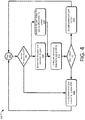
- FIG. 4 shows an example process flowchart 400 illustrating an example method for implementing preemptive - AGC system in a receiver circuitry of a portable device.
- the method may be implemented in any suitable hardware, software, firmware, or a combination thereof, without departing from the scope of the invention, as defined by the appended claims.
- the information 322 may include the occurrence frequency, time of transmission, period of transmission, and the transmitting power of the transmitted signal 210 in the second RF signal 204.
- the detector component 318 may be configured to obtain the information 322.
- determining an occurrence frequency of the second RF signal is performed.
- the occurrence frequency may be derived from the obtained information 322.
- the detector component 318 may be configured to compare the determined occurrence frequency to a threshold value.
- the threshold value is configured to include a value that corresponds to a minimum number of occurrence frequency to justify enabling of the preemptive - AGC 320.
- a determination of a gain setting adjustment of the preemptive - AGC 320 is performed.
- the gain setting adjustment may be derived from the LUT that further utilizes the obtained information 322 of the second RF signal 204.
- the gain setting adjustment may be implemented through the use the stored interference-history at block 408, which also utilizes the obtained information 322.
- the gain setting adjustment at block 406 or 408, through the use of the preemptive - AGC 320 may generate the interference - free first RF signal 202.
- the preemptive - AGC is disabled when the occurrence frequency is lower than the threshold value
- calculating a MDS is performed.
- the detector component 318 is configured to calculate the MDS threshold that corresponds to a particular gain setting where the signal strength quality of the receiver circuitry 304 of the portable device 102 is maintained.
- comparing a RSSI of the interference-free second frequency RF signal to the MDS is performed. For example, in a case where the RSSI is greater than the MDS, then at block 416, the preemptive - AGC 320 is enabled. In other words, a manual gain setting is implemented in the receiver circuitry 304 of the portable device 102. Otherwise, the preemptive - AGC 320 is disabled.
Landscapes
- Engineering & Computer Science (AREA)
- Computer Networks & Wireless Communication (AREA)
- Signal Processing (AREA)
- Circuits Of Receivers In General (AREA)
- Noise Elimination (AREA)
- Mobile Radio Communication Systems (AREA)
Claims (15)
- Verfahren zur Abschwächung von Interferenzen in einem Empfänger einer Vorrichtung, umfassend:Empfangen und Verarbeiten eines Datenpakets eines ersten Hochfrequenz- (HF-) Signals;Erkennen eines kollokierten oder externen zweiten HF-Signals während des Verarbeitens des Datenpakets;Anpassen einer Verstärkungseinstellung einer aktivierten präventiven automatischen Verstärkungsregelung (AGC) in Reaktion auf das Erkennen des zweiten HF-Signals, um ein interferenzfreies erstes HF-Signal zu erzeugen; undDemodulieren eines empfangenen Datenpakets des interferenzfreien ersten HF-Signals;wobei das Verfahren durch Folgendes gekennzeichnet ist:Messen eines Empfangssignalstärkeindikators (RSSI) des interferenzfreien ersten HF-Signals;Vergleichen (414) des gemessenen RSSI mit einem kleinsten erkennbaren Signal (MDS), wobei das MDS eine bestimmte präventive AGC-Verstärkungseinstellung umfasst, die einem kleinsten RSSI zur Signalerkennung entspricht; undAktivieren (416) der präventiven AGC, wenn das gemessene RSSI dem MDS entspricht.
- Verfahren nach Anspruch 1, wobei das Anpassen der Verstärkungseinstellung des aktivierten präventiven AGC Referenzieren einer Lookup-Tabelle (LUT) umfasst.
- Verfahren nach Anspruch 1, wobei das Anpassen der Verstärkungseinstellung der aktivierten AGC Referenzieren eines gespeicherten Interferenzverlaufs umfasst, der eine letzte Einstellungsanpassung umfasst, die Datenpaketfehler in vorigen Datenpaketen eliminiert hat.
- Verfahren nach Anspruch 1, wobei Erkennen des kollokierten oder externen zweiten HF-Signals Referenzieren von Informationen umfasst, die von einer Übertragungseinrichtung des zweiten HF-Signals empfangen wurden.
- Verfahren nach Anspruch 4, wobei die Informationen eine Höhe von Übertragungsleistung und eine Übertragungszeitdauer des zweiten HF-Signals umfassen.
- Verfahren nach Anspruch 1, wobei Empfangen des Datenpakets eines ersten Hochfrequenz- (HF-) Signals Empfangen des Datenpakets über mindestens eine von einer Bluetooth- (BT-) Kommunikationsverbindung, einer Nahfeldkommunikations- (NFC-) Kommunikationsverbindung, einer Wi-Fi-Kommunikationsverbindung, einer 3G-Kommunikationsverbindung, einer 4G-Kommunikationsverbindung oder einer LTE-Kommunikationsverbindung umfasst.
- Verfahren nach einem der Ansprüche 1 bis 6, wobei Erkennen des kollokierten oder externen zweiten HF-Signals Referenzieren von Informationen umfasst, die in Echtzeit von dem Empfänger gemessen werden, wobei die Informationen eine Höhe von Übertragungsleistung und eine Übertragungszeitdauer des zweiten HF-Signals umfassen.
- Verfahren nach Anspruch 1, ferner aufweisend:Vergleichen (404) einer Häufigkeit des Auftretens des zweiten HF-Signals mit einem Schwellenwert; undAktivieren (416) des präventiven AGC, wenn die Häufigkeit des Auftretens dem Schwellenwert entspricht.
- Vorrichtungsempfänger, umfassend:einen Prozessor, der konfiguriert ist, ein Datenpaket eines ersten Hochfrequenz- (HF-) Signals zu verarbeiten;eine Detektorkomponente (318), die konfiguriert ist, während des Verarbeitens des Datenpakets Informationen über ein kollokiertes oder externes zweites HF-Signal in Echtzeit zu empfangen oder zu messen, wobei die Informationen eine Höhe von Übertragungsleistung und eine Übertragungszeit des zweiten HF-Signals umfassen; undeine Komponente (420) zur präventiven automatischen Verstärkungsregelung (AGC), die konfiguriert ist, eine Verstärkungseinstellungsanpassung auf Grundlage der empfangenen oder gemessenen Informationen zu implementieren;wobei die Detektorkomponente (318) ferner konfiguriert ist:einen Empfangssignalstärkeindikator (RSSI) eines interferenzfreien ersten HF-Signals zu messen; undden gemessenen RSSI mit einem kleinsten erkennbaren Signal (MDS) zu vergleichen, wobei die präventive AGC für den RSSI aktiviert ist, der dem MDS entspricht.
- Vorrichtungsempfänger nach Anspruch 9, wobei die Detektorkomponente ferner konfiguriert ist:
eine Häufigkeit des Auftretens des zweiten HF-Signals mit einem Schwellenwert zu vergleichen, wobei die präventive AGC für die Häufigkeit des Auftretens aktiviert ist, die dem Schwellenwert entspricht. - Vorrichtung nach Anspruch 10, wobei die präventive AGC-Komponente deaktiviert ist und ein Modus zur automatischen Verstärkungsregelung (AGC) aktiviert ist, wenn der Schwellenwert oder das MDS nicht erreicht wird.
- Vorrichtungsempfänger nach Anspruch 9, wobei das Anpassen der Verstärkungseinstellung der präventiven AGC auf einer Lookup-Tabelle (LUT) basiert, die die empfangenen oder gemessenen Informationen nutzt.
- Vorrichtungsempfänger nach Anspruch 9, wobei das Datenpaket des ersten Hochfrequenz- (HF-) Signals Empfangen des Datenpakets über mindestens eine von einer Bluetooth- (BT-) Kommunikationsverbindung, einer Nahfeldkommunikations- (NFC-) Kommunikationsverbindung, einer Wi-Fi-Kommunikationsverbindung, einer 3G-Kommunikationsverbindung, einer 4G-Kommunikationsverbindung oder einer LTE-Kommunikationsverbindung umfasst.
- Vorrichtungsempfänger nach Anspruch 9, wobei das Datenpaket des zweiten Hochfrequenz- (HF-) Signals Empfangen des Datenpakets über mindestens eine von einer Bluetooth- (BT-) Kommunikationsverbindung, einer Nahfeldkommunikations- (NFC-) Kommunikationsverbindung, einer Wi-Fi-Kommunikationsverbindung, einer 3G-Kommunikationsverbindung, einer 4G-Kommunikationsverbindung oder einer LTE-Kommunikationsverbindung umfasst.
- Vorrichtungsempfänger nach Anspruch 9, wobei die Verstärkungseinstellungsanpassung der präventiven AGC auf einem gespeicherten Interferenzverlauf basiert, der eine letzte Einstellungsanpassung umfasst, die Datenpaketfehler in vorigen Datenpaketen eliminiert hat.
Applications Claiming Priority (1)
| Application Number | Priority Date | Filing Date | Title |
|---|---|---|---|
| US14/753,529 US9900852B2 (en) | 2015-06-29 | 2015-06-29 | Preemptive automatic gain control (AGC) for interference mitigation |
Publications (2)
| Publication Number | Publication Date |
|---|---|
| EP3113370A1 EP3113370A1 (de) | 2017-01-04 |
| EP3113370B1 true EP3113370B1 (de) | 2018-10-17 |
Family
ID=56092753
Family Applications (1)
| Application Number | Title | Priority Date | Filing Date |
|---|---|---|---|
| EP16171197.3A Active EP3113370B1 (de) | 2015-06-29 | 2016-05-24 | Präventive automatische verstärkungsregelung zur interferenzabschwächung |
Country Status (4)
| Country | Link |
|---|---|
| US (1) | US9900852B2 (de) |
| EP (1) | EP3113370B1 (de) |
| JP (1) | JP6312743B2 (de) |
| CN (1) | CN106301412B (de) |
Families Citing this family (10)
| Publication number | Priority date | Publication date | Assignee | Title |
|---|---|---|---|---|
| US10098136B1 (en) * | 2017-06-29 | 2018-10-09 | Amazon Technologies, Inc. | Transmit power and receive gain adjustments in multi-radio devices |
| EP3588882A1 (de) | 2018-06-29 | 2020-01-01 | Nxp B.V. | Teilweise nutzung eines sc-fdma automatischen verstärkungsregelungssymbols zur decodierung |
| US11044028B2 (en) * | 2018-07-12 | 2021-06-22 | Silicon Laboratories Inc. | Apparatus for radio-frequency receiver with interference detection and associated methods |
| US10615829B1 (en) * | 2019-03-19 | 2020-04-07 | Cypress Semiconductor Corporation | Systems and methods for adjusting receive sensitivity using collocated communication circuitry |
| US11523340B2 (en) * | 2020-11-29 | 2022-12-06 | Silicon Laboratories Inc. | Delayed preamble detection for Bluetooth® receiver based on interferer metrics |
| US11483020B1 (en) | 2021-05-04 | 2022-10-25 | Nxp Usa, Inc. | Gain adjustment circuit |
| US11770779B2 (en) * | 2021-05-21 | 2023-09-26 | Hughes Network Systems | Wide-band automated gain control for bursty frames |
| CN117375743A (zh) * | 2022-06-30 | 2024-01-09 | 上海星思半导体有限责任公司 | 快速自动增益控制方法、装置、电子设备及可读存储介质 |
| CN117713850A (zh) * | 2024-01-02 | 2024-03-15 | 中国人民解放军国防科技大学 | 基于自适应agc的干扰检测方法、装置和设备 |
| CN119676816B (zh) * | 2024-12-04 | 2025-10-28 | 北京玄戒技术有限公司 | 接收链路的agc方法、装置、电子设备、芯片和存储介质 |
Family Cites Families (6)
| Publication number | Priority date | Publication date | Assignee | Title |
|---|---|---|---|---|
| US7215703B2 (en) * | 2003-02-14 | 2007-05-08 | Broadcom Corporation | Digital calculation received signal strength indication |
| WO2008145799A1 (en) | 2007-05-25 | 2008-12-04 | Nokia Corporation | Interference in communication devices |
| US8559865B2 (en) * | 2008-07-31 | 2013-10-15 | Qualcomm Incorporated | Method and apparatus for providing jammer detection in a receiver |
| US8718207B2 (en) | 2011-05-10 | 2014-05-06 | Issc Technologies Corp. | Method used for providing an adaptive receiving in wireless communication |
| US8737545B2 (en) * | 2011-12-14 | 2014-05-27 | Posedge Inc. | Receiver chain gain selection |
| US9544862B2 (en) | 2013-06-21 | 2017-01-10 | Telefonaktiebolaget L M Ericsson (Publ) | Method and device for performing automatic gain control |
-
2015
- 2015-06-29 US US14/753,529 patent/US9900852B2/en not_active Expired - Fee Related
-
2016
- 2016-05-24 EP EP16171197.3A patent/EP3113370B1/de active Active
- 2016-05-27 JP JP2016106169A patent/JP6312743B2/ja active Active
- 2016-05-27 CN CN201610365990.8A patent/CN106301412B/zh not_active Expired - Fee Related
Non-Patent Citations (1)
| Title |
|---|
| None * |
Also Published As
| Publication number | Publication date |
|---|---|
| CN106301412A (zh) | 2017-01-04 |
| US9900852B2 (en) | 2018-02-20 |
| JP2017017680A (ja) | 2017-01-19 |
| EP3113370A1 (de) | 2017-01-04 |
| US20160381647A1 (en) | 2016-12-29 |
| CN106301412B (zh) | 2019-09-20 |
| JP6312743B2 (ja) | 2018-04-18 |
Similar Documents
| Publication | Publication Date | Title |
|---|---|---|
| US9900852B2 (en) | Preemptive automatic gain control (AGC) for interference mitigation | |
| US20130324065A1 (en) | Method and Apparatus for Auto Gain Control in Radio Receiver | |
| JPWO2013008747A1 (ja) | 受信装置及び利得制御方法 | |
| US9544862B2 (en) | Method and device for performing automatic gain control | |
| EP3090489B1 (de) | Verfahren zur einstellung von lo-frequenzen bei einem empfänger und zugehöriger empfänger | |
| US8213891B2 (en) | Gain control apparatus and method in receiver of multiband OFDM system | |
| US12113563B2 (en) | Methods and devices for power management techniques with time averaged SAR and proximity sensor considerations | |
| US8804882B2 (en) | Receiving apparatus, and computer readable memory medium that stores a program | |
| EP3079413B1 (de) | Halbleiterbauelement, funkkommunikationsvorrichtung und steuerungsverfahren für die funkkommunikationsvorrichtung | |
| KR100922947B1 (ko) | 무선통신 시스템의 수신기에서 이득 제어 방법 및 장치 | |
| US8849187B2 (en) | Radio frequency amplifier noise reduction system | |
| US9391814B2 (en) | FM receiver that receives FM signal and method for receiving FM signal | |
| US8655295B2 (en) | Receiving apparatus | |
| KR20160070579A (ko) | 통신 시스템에서 이득 제어를 위한 방법 및 장치 | |
| US9300334B2 (en) | Anti-interference method and device for a wireless communication system | |
| EP3024150B1 (de) | Genaue desensibilisierungsschätzung eines empfängers | |
| US9065525B1 (en) | Receiving apparatus | |
| EP3069457B1 (de) | Verbesserter überlastschutz für empfänger | |
| US20130064145A1 (en) | Method, apparatus and computer program for setting a radio frequency gain | |
| US11848750B2 (en) | Radio frequency interference mitigation with adaptive local oscillator | |
| JP4328611B2 (ja) | スペクトラム拡散通信装置 | |
| KR20100127450A (ko) | 무선 수신기의 자동이득 제어장치 | |
| US10979261B2 (en) | Receive device, recording medium for receiving signal | |
| JP2006203410A (ja) | 干渉波検出回路及びその干渉波検出回路を有する送受信機 | |
| KR20150094141A (ko) | 무선 통신 시스템에서 인접 채널 간섭을 고려한 전력 이득 제어 장치 및 방법 |
Legal Events
| Date | Code | Title | Description |
|---|---|---|---|
| PUAI | Public reference made under article 153(3) epc to a published international application that has entered the european phase |
Free format text: ORIGINAL CODE: 0009012 |
|
| STAA | Information on the status of an ep patent application or granted ep patent |
Free format text: STATUS: REQUEST FOR EXAMINATION WAS MADE |
|
| 17P | Request for examination filed |
Effective date: 20160524 |
|
| AK | Designated contracting states |
Kind code of ref document: A1 Designated state(s): AL AT BE BG CH CY CZ DE DK EE ES FI FR GB GR HR HU IE IS IT LI LT LU LV MC MK MT NL NO PL PT RO RS SE SI SK SM TR |
|
| AX | Request for extension of the european patent |
Extension state: BA ME |
|
| GRAP | Despatch of communication of intention to grant a patent |
Free format text: ORIGINAL CODE: EPIDOSNIGR1 |
|
| STAA | Information on the status of an ep patent application or granted ep patent |
Free format text: STATUS: GRANT OF PATENT IS INTENDED |
|
| RIC1 | Information provided on ipc code assigned before grant |
Ipc: H03G 3/30 20060101ALI20180322BHEP Ipc: H04B 1/10 20060101ALI20180322BHEP Ipc: H04B 1/12 20060101AFI20180322BHEP |
|
| INTG | Intention to grant announced |
Effective date: 20180423 |
|
| RIN1 | Information on inventor provided before grant (corrected) |
Inventor name: LAVIE, REUVEN Inventor name: CHAY, DOR Inventor name: TSANGAROPOULOS, ANTHONY Inventor name: SHAHAR, ITZIK Inventor name: BI, DONGSHENG Inventor name: SUBLETT, BRIAN J. Inventor name: LEE, JINYONG |
|
| GRAS | Grant fee paid |
Free format text: ORIGINAL CODE: EPIDOSNIGR3 |
|
| GRAA | (expected) grant |
Free format text: ORIGINAL CODE: 0009210 |
|
| STAA | Information on the status of an ep patent application or granted ep patent |
Free format text: STATUS: THE PATENT HAS BEEN GRANTED |
|
| AK | Designated contracting states |
Kind code of ref document: B1 Designated state(s): AL AT BE BG CH CY CZ DE DK EE ES FI FR GB GR HR HU IE IS IT LI LT LU LV MC MK MT NL NO PL PT RO RS SE SI SK SM TR |
|
| REG | Reference to a national code |
Ref country code: GB Ref legal event code: FG4D |
|
| REG | Reference to a national code |
Ref country code: CH Ref legal event code: EP |
|
| REG | Reference to a national code |
Ref country code: IE Ref legal event code: FG4D |
|
| REG | Reference to a national code |
Ref country code: DE Ref legal event code: R096 Ref document number: 602016006383 Country of ref document: DE Ref country code: AT Ref legal event code: REF Ref document number: 1055198 Country of ref document: AT Kind code of ref document: T Effective date: 20181115 |
|
| REG | Reference to a national code |
Ref country code: NL Ref legal event code: FP |
|
| REG | Reference to a national code |
Ref country code: LT Ref legal event code: MG4D |
|
| REG | Reference to a national code |
Ref country code: AT Ref legal event code: MK05 Ref document number: 1055198 Country of ref document: AT Kind code of ref document: T Effective date: 20181017 |
|
| PG25 | Lapsed in a contracting state [announced via postgrant information from national office to epo] |
Ref country code: IS Free format text: LAPSE BECAUSE OF FAILURE TO SUBMIT A TRANSLATION OF THE DESCRIPTION OR TO PAY THE FEE WITHIN THE PRESCRIBED TIME-LIMIT Effective date: 20190217 Ref country code: FI Free format text: LAPSE BECAUSE OF FAILURE TO SUBMIT A TRANSLATION OF THE DESCRIPTION OR TO PAY THE FEE WITHIN THE PRESCRIBED TIME-LIMIT Effective date: 20181017 Ref country code: LT Free format text: LAPSE BECAUSE OF FAILURE TO SUBMIT A TRANSLATION OF THE DESCRIPTION OR TO PAY THE FEE WITHIN THE PRESCRIBED TIME-LIMIT Effective date: 20181017 Ref country code: PL Free format text: LAPSE BECAUSE OF FAILURE TO SUBMIT A TRANSLATION OF THE DESCRIPTION OR TO PAY THE FEE WITHIN THE PRESCRIBED TIME-LIMIT Effective date: 20181017 Ref country code: BG Free format text: LAPSE BECAUSE OF FAILURE TO SUBMIT A TRANSLATION OF THE DESCRIPTION OR TO PAY THE FEE WITHIN THE PRESCRIBED TIME-LIMIT Effective date: 20190117 Ref country code: HR Free format text: LAPSE BECAUSE OF FAILURE TO SUBMIT A TRANSLATION OF THE DESCRIPTION OR TO PAY THE FEE WITHIN THE PRESCRIBED TIME-LIMIT Effective date: 20181017 Ref country code: LV Free format text: LAPSE BECAUSE OF FAILURE TO SUBMIT A TRANSLATION OF THE DESCRIPTION OR TO PAY THE FEE WITHIN THE PRESCRIBED TIME-LIMIT Effective date: 20181017 Ref country code: ES Free format text: LAPSE BECAUSE OF FAILURE TO SUBMIT A TRANSLATION OF THE DESCRIPTION OR TO PAY THE FEE WITHIN THE PRESCRIBED TIME-LIMIT Effective date: 20181017 Ref country code: NO Free format text: LAPSE BECAUSE OF FAILURE TO SUBMIT A TRANSLATION OF THE DESCRIPTION OR TO PAY THE FEE WITHIN THE PRESCRIBED TIME-LIMIT Effective date: 20190117 Ref country code: AT Free format text: LAPSE BECAUSE OF FAILURE TO SUBMIT A TRANSLATION OF THE DESCRIPTION OR TO PAY THE FEE WITHIN THE PRESCRIBED TIME-LIMIT Effective date: 20181017 |
|
| PG25 | Lapsed in a contracting state [announced via postgrant information from national office to epo] |
Ref country code: PT Free format text: LAPSE BECAUSE OF FAILURE TO SUBMIT A TRANSLATION OF THE DESCRIPTION OR TO PAY THE FEE WITHIN THE PRESCRIBED TIME-LIMIT Effective date: 20190217 Ref country code: AL Free format text: LAPSE BECAUSE OF FAILURE TO SUBMIT A TRANSLATION OF THE DESCRIPTION OR TO PAY THE FEE WITHIN THE PRESCRIBED TIME-LIMIT Effective date: 20181017 Ref country code: GR Free format text: LAPSE BECAUSE OF FAILURE TO SUBMIT A TRANSLATION OF THE DESCRIPTION OR TO PAY THE FEE WITHIN THE PRESCRIBED TIME-LIMIT Effective date: 20190118 Ref country code: RS Free format text: LAPSE BECAUSE OF FAILURE TO SUBMIT A TRANSLATION OF THE DESCRIPTION OR TO PAY THE FEE WITHIN THE PRESCRIBED TIME-LIMIT Effective date: 20181017 Ref country code: SE Free format text: LAPSE BECAUSE OF FAILURE TO SUBMIT A TRANSLATION OF THE DESCRIPTION OR TO PAY THE FEE WITHIN THE PRESCRIBED TIME-LIMIT Effective date: 20181017 |
|
| REG | Reference to a national code |
Ref country code: DE Ref legal event code: R097 Ref document number: 602016006383 Country of ref document: DE |
|
| PG25 | Lapsed in a contracting state [announced via postgrant information from national office to epo] |
Ref country code: IT Free format text: LAPSE BECAUSE OF FAILURE TO SUBMIT A TRANSLATION OF THE DESCRIPTION OR TO PAY THE FEE WITHIN THE PRESCRIBED TIME-LIMIT Effective date: 20181017 Ref country code: CZ Free format text: LAPSE BECAUSE OF FAILURE TO SUBMIT A TRANSLATION OF THE DESCRIPTION OR TO PAY THE FEE WITHIN THE PRESCRIBED TIME-LIMIT Effective date: 20181017 Ref country code: DK Free format text: LAPSE BECAUSE OF FAILURE TO SUBMIT A TRANSLATION OF THE DESCRIPTION OR TO PAY THE FEE WITHIN THE PRESCRIBED TIME-LIMIT Effective date: 20181017 |
|
| PLBE | No opposition filed within time limit |
Free format text: ORIGINAL CODE: 0009261 |
|
| STAA | Information on the status of an ep patent application or granted ep patent |
Free format text: STATUS: NO OPPOSITION FILED WITHIN TIME LIMIT |
|
| PG25 | Lapsed in a contracting state [announced via postgrant information from national office to epo] |
Ref country code: SK Free format text: LAPSE BECAUSE OF FAILURE TO SUBMIT A TRANSLATION OF THE DESCRIPTION OR TO PAY THE FEE WITHIN THE PRESCRIBED TIME-LIMIT Effective date: 20181017 Ref country code: RO Free format text: LAPSE BECAUSE OF FAILURE TO SUBMIT A TRANSLATION OF THE DESCRIPTION OR TO PAY THE FEE WITHIN THE PRESCRIBED TIME-LIMIT Effective date: 20181017 Ref country code: SM Free format text: LAPSE BECAUSE OF FAILURE TO SUBMIT A TRANSLATION OF THE DESCRIPTION OR TO PAY THE FEE WITHIN THE PRESCRIBED TIME-LIMIT Effective date: 20181017 Ref country code: EE Free format text: LAPSE BECAUSE OF FAILURE TO SUBMIT A TRANSLATION OF THE DESCRIPTION OR TO PAY THE FEE WITHIN THE PRESCRIBED TIME-LIMIT Effective date: 20181017 |
|
| PGFP | Annual fee paid to national office [announced via postgrant information from national office to epo] |
Ref country code: FR Payment date: 20190429 Year of fee payment: 4 |
|
| 26N | No opposition filed |
Effective date: 20190718 |
|
| PG25 | Lapsed in a contracting state [announced via postgrant information from national office to epo] |
Ref country code: SI Free format text: LAPSE BECAUSE OF FAILURE TO SUBMIT A TRANSLATION OF THE DESCRIPTION OR TO PAY THE FEE WITHIN THE PRESCRIBED TIME-LIMIT Effective date: 20181017 |
|
| REG | Reference to a national code |
Ref country code: CH Ref legal event code: PL |
|
| PG25 | Lapsed in a contracting state [announced via postgrant information from national office to epo] |
Ref country code: LI Free format text: LAPSE BECAUSE OF NON-PAYMENT OF DUE FEES Effective date: 20190531 Ref country code: CH Free format text: LAPSE BECAUSE OF NON-PAYMENT OF DUE FEES Effective date: 20190531 Ref country code: MC Free format text: LAPSE BECAUSE OF FAILURE TO SUBMIT A TRANSLATION OF THE DESCRIPTION OR TO PAY THE FEE WITHIN THE PRESCRIBED TIME-LIMIT Effective date: 20181017 |
|
| REG | Reference to a national code |
Ref country code: BE Ref legal event code: MM Effective date: 20190531 |
|
| PG25 | Lapsed in a contracting state [announced via postgrant information from national office to epo] |
Ref country code: LU Free format text: LAPSE BECAUSE OF NON-PAYMENT OF DUE FEES Effective date: 20190524 |
|
| PG25 | Lapsed in a contracting state [announced via postgrant information from national office to epo] |
Ref country code: TR Free format text: LAPSE BECAUSE OF FAILURE TO SUBMIT A TRANSLATION OF THE DESCRIPTION OR TO PAY THE FEE WITHIN THE PRESCRIBED TIME-LIMIT Effective date: 20181017 |
|
| PG25 | Lapsed in a contracting state [announced via postgrant information from national office to epo] |
Ref country code: IE Free format text: LAPSE BECAUSE OF NON-PAYMENT OF DUE FEES Effective date: 20190524 |
|
| PG25 | Lapsed in a contracting state [announced via postgrant information from national office to epo] |
Ref country code: BE Free format text: LAPSE BECAUSE OF NON-PAYMENT OF DUE FEES Effective date: 20190531 |
|
| GBPC | Gb: european patent ceased through non-payment of renewal fee |
Effective date: 20200524 |
|
| PG25 | Lapsed in a contracting state [announced via postgrant information from national office to epo] |
Ref country code: FR Free format text: LAPSE BECAUSE OF NON-PAYMENT OF DUE FEES Effective date: 20200531 Ref country code: GB Free format text: LAPSE BECAUSE OF NON-PAYMENT OF DUE FEES Effective date: 20200524 |
|
| PG25 | Lapsed in a contracting state [announced via postgrant information from national office to epo] |
Ref country code: CY Free format text: LAPSE BECAUSE OF FAILURE TO SUBMIT A TRANSLATION OF THE DESCRIPTION OR TO PAY THE FEE WITHIN THE PRESCRIBED TIME-LIMIT Effective date: 20181017 |
|
| REG | Reference to a national code |
Ref country code: NL Ref legal event code: PD Owner name: INTEL CORPORATION; US Free format text: DETAILS ASSIGNMENT: CHANGE OF OWNER(S), ASSIGNMENT; FORMER OWNER NAME: INTEL IP CORPORATION Effective date: 20210623 |
|
| PG25 | Lapsed in a contracting state [announced via postgrant information from national office to epo] |
Ref country code: HU Free format text: LAPSE BECAUSE OF FAILURE TO SUBMIT A TRANSLATION OF THE DESCRIPTION OR TO PAY THE FEE WITHIN THE PRESCRIBED TIME-LIMIT; INVALID AB INITIO Effective date: 20160524 Ref country code: MT Free format text: LAPSE BECAUSE OF FAILURE TO SUBMIT A TRANSLATION OF THE DESCRIPTION OR TO PAY THE FEE WITHIN THE PRESCRIBED TIME-LIMIT Effective date: 20181017 |
|
| REG | Reference to a national code |
Ref country code: DE Ref legal event code: R081 Ref document number: 602016006383 Country of ref document: DE Owner name: INTEL CORPORATION, SANTA CLARA, US Free format text: FORMER OWNER: INTEL IP CORP., SANTA CLARA, CALIF., US |
|
| PG25 | Lapsed in a contracting state [announced via postgrant information from national office to epo] |
Ref country code: MK Free format text: LAPSE BECAUSE OF FAILURE TO SUBMIT A TRANSLATION OF THE DESCRIPTION OR TO PAY THE FEE WITHIN THE PRESCRIBED TIME-LIMIT Effective date: 20181017 |
|
| P01 | Opt-out of the competence of the unified patent court (upc) registered |
Effective date: 20230518 |
|
| PGFP | Annual fee paid to national office [announced via postgrant information from national office to epo] |
Ref country code: NL Payment date: 20230426 Year of fee payment: 8 |
|
| REG | Reference to a national code |
Ref country code: NL Ref legal event code: MM Effective date: 20240601 |
|
| PG25 | Lapsed in a contracting state [announced via postgrant information from national office to epo] |
Ref country code: NL Free format text: LAPSE BECAUSE OF NON-PAYMENT OF DUE FEES Effective date: 20240601 |
|
| PGFP | Annual fee paid to national office [announced via postgrant information from national office to epo] |
Ref country code: DE Payment date: 20260331 Year of fee payment: 11 |