EP3112731A1 - Preshaped duckbill valve - Google Patents
Preshaped duckbill valve Download PDFInfo
- Publication number
- EP3112731A1 EP3112731A1 EP16176966.6A EP16176966A EP3112731A1 EP 3112731 A1 EP3112731 A1 EP 3112731A1 EP 16176966 A EP16176966 A EP 16176966A EP 3112731 A1 EP3112731 A1 EP 3112731A1
- Authority
- EP
- European Patent Office
- Prior art keywords
- lip
- valve
- base end
- slit
- valve according
- Prior art date
- Legal status (The legal status is an assumption and is not a legal conclusion. Google has not performed a legal analysis and makes no representation as to the accuracy of the status listed.)
- Granted
Links
Images


Classifications
-
- F—MECHANICAL ENGINEERING; LIGHTING; HEATING; WEAPONS; BLASTING
- F16—ENGINEERING ELEMENTS AND UNITS; GENERAL MEASURES FOR PRODUCING AND MAINTAINING EFFECTIVE FUNCTIONING OF MACHINES OR INSTALLATIONS; THERMAL INSULATION IN GENERAL
- F16K—VALVES; TAPS; COCKS; ACTUATING-FLOATS; DEVICES FOR VENTING OR AERATING
- F16K15/00—Check valves
- F16K15/14—Check valves with flexible valve members
- F16K15/16—Check valves with flexible valve members with tongue-shaped laminae
-
- F—MECHANICAL ENGINEERING; LIGHTING; HEATING; WEAPONS; BLASTING
- F16—ENGINEERING ELEMENTS AND UNITS; GENERAL MEASURES FOR PRODUCING AND MAINTAINING EFFECTIVE FUNCTIONING OF MACHINES OR INSTALLATIONS; THERMAL INSULATION IN GENERAL
- F16K—VALVES; TAPS; COCKS; ACTUATING-FLOATS; DEVICES FOR VENTING OR AERATING
- F16K15/00—Check valves
- F16K15/14—Check valves with flexible valve members
- F16K15/144—Check valves with flexible valve members the closure elements being fixed along all or a part of their periphery
- F16K15/147—Check valves with flexible valve members the closure elements being fixed along all or a part of their periphery the closure elements having specially formed slits or being of an elongated easily collapsible form
-
- F—MECHANICAL ENGINEERING; LIGHTING; HEATING; WEAPONS; BLASTING
- F16—ENGINEERING ELEMENTS AND UNITS; GENERAL MEASURES FOR PRODUCING AND MAINTAINING EFFECTIVE FUNCTIONING OF MACHINES OR INSTALLATIONS; THERMAL INSULATION IN GENERAL
- F16K—VALVES; TAPS; COCKS; ACTUATING-FLOATS; DEVICES FOR VENTING OR AERATING
- F16K17/00—Safety valves; Equalising valves, e.g. pressure relief valves
- F16K17/02—Safety valves; Equalising valves, e.g. pressure relief valves opening on surplus pressure on one side; closing on insufficient pressure on one side
- F16K17/14—Safety valves; Equalising valves, e.g. pressure relief valves opening on surplus pressure on one side; closing on insufficient pressure on one side with fracturing member
- F16K17/16—Safety valves; Equalising valves, e.g. pressure relief valves opening on surplus pressure on one side; closing on insufficient pressure on one side with fracturing member with fracturing diaphragm ; Rupture discs
- F16K17/1633—Safety valves; Equalising valves, e.g. pressure relief valves opening on surplus pressure on one side; closing on insufficient pressure on one side with fracturing member with fracturing diaphragm ; Rupture discs made of graphite
-
- F—MECHANICAL ENGINEERING; LIGHTING; HEATING; WEAPONS; BLASTING
- F16—ENGINEERING ELEMENTS AND UNITS; GENERAL MEASURES FOR PRODUCING AND MAINTAINING EFFECTIVE FUNCTIONING OF MACHINES OR INSTALLATIONS; THERMAL INSULATION IN GENERAL
- F16K—VALVES; TAPS; COCKS; ACTUATING-FLOATS; DEVICES FOR VENTING OR AERATING
- F16K27/00—Construction of housing; Use of materials therefor
- F16K27/02—Construction of housing; Use of materials therefor of lift valves
- F16K27/0209—Check valves or pivoted valves
Definitions
- the present invention relates to a valve for defining a one-way flow having one pair of lips that are arranged in a converging relationship, wherein each lip has a lip base end and a lip outer end, wherein the lip base ends form part of an open valve base end and the lip outer ends are disposed adjacent each other to define one slit, wherein the valve further comprises a flange extending outwardly at the valve base end.
- duckbill valves are unique, one-piece, elastomeric components that function as backflow prevention devices or one-way valves or check valves. They have elastomeric lips in the shape of a duckbill which prevent backflow and allow forward flow only.
- the main advantage of duckbill valves over other types of one-way valves is that duckbill valves are self-contained i.e. the critical sealing function is an integral part of the one-piece elastomeric component as opposed to valves where a sealing element has to engage with a smooth seat surface to form a seal.
- duckbill valves are easily incorporated and assembled into a wide variety of devices without the problems associated with the surface finish quality of mating seats and/or complex assembly processes.
- Duckbill valves are available in various elastomeric materials, including medical and food-grade silicone and hydrocarbon-resistant fluorosilicone rubber to handle a broad range of media and temperatures. Areas of application range from long-term service in harsh environments, such as in durable chemical pumps, to the high-volume use in disposable intravenous fluid delivery sets and from one-way valves used in automotive fuel pumps to delicate valves used in tubing circuits for heart surgery, soap dispensers, coffee makers, anti- siphoning valves in shower heads and toys.
- each lip base end runs along one or more substantially straight lines and each lip is provided with one or more folding lines running over the surface of the lip from the lip base end towards the slit.
- the lips of the valve according to the invention are connected or hinged to the flange by straight lines.
- Each straight line defines a folding area, surrounding the straight line, for the lips with respect to the flange that allow the valve to open easily at a low opening pressure while offering a higher flow per unit area.
- the folding lines preshape the lips in the direction of flow and advantageously reduce the resistance for the opening of the valve. Due to the folding lines tension in the valve or material stress can be avoided.
- the straight lines of the valve base end generally form a polygon and at least one of the folding lines starts at an angle of the polygon and ends at the slit.
- the polygon has many straight lines by which the lip is hinged to the flange. The increased number of straight hinge lines further improves the flow characteristics of the valve according to the present invention.
- the polygon may be a parallelogram or a diamond. Both shapes allow for an easy production of the valve according to the invention.
- At least one of the folding lines is a straight line that more preferably runs substantially perpendicular with respect to the slit.
- two or more folding lines run over the surface of the lip from the lip base end converging in the direction of the slit. More folding lines preshape the lips even better in the direction of flow and further reduce the resistance for the opening of the valve.
- a number of the lip sections are curved in two mutually perpendicular directions.
- the curved surface of the lip sections significantly reduces the resistance for the opening of the valve.
- the slit is arcuate or at an angle. Both preferred embodiments allow for a larger slit to be formed in a valve of the same width that will allow the valve to open further allowing a larger flow.
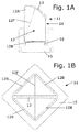
- FIG. 1A schematically shows a first preferred embodiment of the valve 11 according to the invention.
- Figure 1B shows valve 11 schematically in top view.
- Valve 11 comprises one pair of lips 12 that extend in a converging relationship from a valve base to a slit 13.
- Each lip 12 has a lip base end 12B and a lip outer end 12A.
- the lip base ends 12B form part of the open valve base end.
- the lip outer ends 12A are disposed adjacent each other to define the slit 13.
- Each lip base end 12B runs over two substantially straight lines that are at an angle.
- each lip 12 is provided with a folding line 12F defining a folding area running over the surface of the lip 12.
- the folding line 12F starts at the angle between the straight lines of the lip base end 12B and ends at the slit 13.
- the folding line 12F runs substantially perpendicular with respect to the slit 13.
- the lips 12 are interconnected at the sides 14.
- valve base end 12B has a generally parallelogram shape that can clearly be seen in the top view of figure 2B .
- the valve base end 12B has a generally diamond shape.
- slit 13 runs substantially diagonal with respect to the valve base end.
- Valve 11 further comprises a flange 15 extending outwardly at the valve base end.
- the flange 15 has one or more straight sides. More specifically the flange 15 has two opposing straight sides. In the preferred embodiment shown the flange 15 has a generally square shape. The straight sides are interconnected by slightly curved corners.
- a transition part 16 is arranged between the flange 15 and the lips 12.
- the transition part 16 allows a flange shape other than a parallelogram, e.g. circular.
- the folding line divides the lip 12 in two sections having a substantially curved surface.
- the lip sections are curved in two mutually perpendicular directions.
- the folding line 12F is a straight line that runs substantially perpendicular with respect to the slit 13.
- the slit 13 is arcuate and curved outwardly.
- Fig. 2A schematically shows a first variant 11-1 of the valve of figure 1A in closed position.
- the slit 13-1 is formed by one substantially horizontal line in the centre.
- the folding line 12F runs over the surface of the lip 12 from the angle between the straight lines of the lip base end 12B toward the centre of the slit 13-1.
- the variant 11-1 is identical to the embodiment of figures 1A .
- Fig. 2B schematically shows the valve 11-1 in an open position.
- the folding lines 12F preshape the lips 12 and contribute to a low opening pressure of the valve 11-1.
- Fig. 3A schematically shows a second variant of the valve of figure 1A .
- the slit 13-2 is formed by straight lines at an angle that lies in the centre.
- the folding line 12F runs over the surface of the lip 12 from the angle between the straight lines of the lip base end 12B toward the angle in the slit 13-2.
- the variant 11-2 is identical to the embodiments of figures 1A and 2A .
- Fig. 3B schematically shows a third variant 11-3 of the valve of figure 1A .
- the slit 13-2 is arcuate, but curved inwardly.
- the folding line 12F runs over the surface of the lip 12 from the angle between the straight lines of the lip base end 12B toward the centre of the slit 13-3.
- the variant 11-3 is identical to the embodiments of figures 1A , 2A and 3A .
- Fig. 3C schematically shows a fourth variant 11-4 of the valve of figure 1A .
- the flange 15-4 is circular.
- the transition part 16-4 is adapted to connect the valve base end of the lips 12 to the flange 15-4.
- the variant 11-4 is identical to the embodiments of figures 1A , 2A , 3A and 3B .
- the shape of the slit can vary so a larger slit can be formed in a valve of the same width that will allow the valve to open further allowing a larger flow.
- Fig. 4A shows a second preferred embodiment of a valve 21 according to the present invention.
- the straight lines 22B of the valve base end form a hexagon.
- Two folding lines 22F run over the surface of the lip 22 from adjacent angles of the hexagon converging in the direction of the slit 13, more specifically at the slit 13, preferably at the centre of the slit.
- two additional folding lines 23F start from adjacent angles of the hexagon and converge at the same point of the slit 13. Consequently the lip 22 is divided in five lip sections.
- the transition part 26 has a general circular shape and is arranged between the flange 15 and the lips 22.
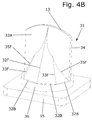
- Fig. 4B shows a third preferred embodiment of a valve 31 according to the present invention.
- the straight lines 32B of the valve base end form an octagon.
- One central folding line 32F runs over the surface of the lip 32 from one angle of the octagon toward the slit 13, preferably toward the centre of the slit.
- a pair of two additional folding lines 33F and 35F start from adjacent angles of the octagon and converge into one folding line that in turn converges with the central folding line 32F at the slit 13. Consequently the lip 32 is divided in six lip sections.
- the invention is based on the inventive thought of providing a one-way valve, specifically a duckbill valve, having lips that are preshaped by lines. Each lip base end runs along one or more substantially straight lines and each lip is provided with one or more folding lines running over the surface of the lip from the lip base end towards the slit.
- the combination of technical features of the valve according to the invention truly approximate the appearance of a duckbill.
- the straight lines of the valve base end generally form a polygon and at least one of the folding lines starts at an angle of the polygon and ends at the slit.
- the folding lines contribute significantly to enhance the flow characteristics of the valve.
- the valve according to the invention is preferably universally suitable and can be manufactured in a range of sizes.
- the valve is designed for cost effective production thus facilitating the use as a disposable article.
- valve has been described in the context of a one-way valve for medical application, more specifically a purge valve, the invention is not limited thereto.
- a person skilled in the art will have no difficulty making small changes to the valve, such as scaling it up, in order to render it suitable for a particular intended use outside this field.
Landscapes
- Engineering & Computer Science (AREA)
- General Engineering & Computer Science (AREA)
- Mechanical Engineering (AREA)
- Check Valves (AREA)
Abstract
Description
- The present invention relates to a valve for defining a one-way flow having one pair of lips that are arranged in a converging relationship, wherein each lip has a lip base end and a lip outer end, wherein the lip base ends form part of an open valve base end and the lip outer ends are disposed adjacent each other to define one slit, wherein the valve further comprises a flange extending outwardly at the valve base end.
- Such a valve is known in the relevant art as a duckbill valve. Duckbill valves are unique, one-piece, elastomeric components that function as backflow prevention devices or one-way valves or check valves. They have elastomeric lips in the shape of a duckbill which prevent backflow and allow forward flow only. The main advantage of duckbill valves over other types of one-way valves is that duckbill valves are self-contained i.e. the critical sealing function is an integral part of the one-piece elastomeric component as opposed to valves where a sealing element has to engage with a smooth seat surface to form a seal. Therefore duckbill valves are easily incorporated and assembled into a wide variety of devices without the problems associated with the surface finish quality of mating seats and/or complex assembly processes. Duckbill valves are available in various elastomeric materials, including medical and food-grade silicone and hydrocarbon-resistant fluorosilicone rubber to handle a broad range of media and temperatures. Areas of application range from long-term service in harsh environments, such as in durable chemical pumps, to the high-volume use in disposable intravenous fluid delivery sets and from one-way valves used in automotive fuel pumps to delicate valves used in tubing circuits for heart surgery, soap dispensers, coffee makers, anti- siphoning valves in shower heads and toys.
- It is an object of the present invention to provide a duckbill valve of the kind as mentioned above that has improved flow and back flow characteristics.
- The valve according to the invention is characterized in that each lip base end runs along one or more substantially straight lines and each lip is provided with one or more folding lines running over the surface of the lip from the lip base end towards the slit.
- The lips of the valve according to the invention are connected or hinged to the flange by straight lines. Each straight line defines a folding area, surrounding the straight line, for the lips with respect to the flange that allow the valve to open easily at a low opening pressure while offering a higher flow per unit area. In addition the folding lines preshape the lips in the direction of flow and advantageously reduce the resistance for the opening of the valve. Due to the folding lines tension in the valve or material stress can be avoided.
- In a preferred embodiment of the valve according to the invention the straight lines of the valve base end generally form a polygon and at least one of the folding lines starts at an angle of the polygon and ends at the slit. The polygon has many straight lines by which the lip is hinged to the flange. The increased number of straight hinge lines further improves the flow characteristics of the valve according to the present invention.
- The polygon may be a parallelogram or a diamond. Both shapes allow for an easy production of the valve according to the invention.
- Preferably at least one of the folding lines is a straight line that more preferably runs substantially perpendicular with respect to the slit.
- In a further preferred embodiment two or more folding lines run over the surface of the lip from the lip base end converging in the direction of the slit. More folding lines preshape the lips even better in the direction of flow and further reduce the resistance for the opening of the valve.
- Preferably a number of the lip sections are curved in two mutually perpendicular directions. The curved surface of the lip sections significantly reduces the resistance for the opening of the valve.
- Preferably the slit is arcuate or at an angle. Both preferred embodiments allow for a larger slit to be formed in a valve of the same width that will allow the valve to open further allowing a larger flow.
- These and other features and advantages of the invention will be more apparent with a discussion of various preferred embodiments of the invention and reference to the associated drawings.
- The invention will be explained in more detail with reference to the appended drawings, in which:
-
Fig. 1A schematically shows a first preferred embodiment of a valve according to the present invention; -
Fig. 1B schematically shows the valve offigure 1A in top view; -
Fig. 2A schematically shows a first variant of the valve offigure 1A in closed position; -
Fig. 2B schematically shows the valve offigure 2A in an open position; -
Fig. 3A schematically shows a second variant of the valve offigure 1A ; -
Fig. 3B schematically shows a third variant of the valve offigure 1A ; -
Fig. 3C schematically shows a fourth variant of the valve offigure 1A ; -
Fig. 4A shows a second preferred embodiment of a valve according to the present invention; and -
Fig. 4B shows a third preferred embodiment of a valve according to the present invention. -
Figure 1A schematically shows a first preferred embodiment of thevalve 11 according to the invention.Figure 1B showsvalve 11 schematically in top view. Valve 11 comprises one pair oflips 12 that extend in a converging relationship from a valve base to aslit 13. Eachlip 12 has alip base end 12B and a lipouter end 12A. The lip base ends 12B form part of the open valve base end. The lipouter ends 12A are disposed adjacent each other to define theslit 13. - Each
lip base end 12B runs over two substantially straight lines that are at an angle. According to the invention eachlip 12 is provided with afolding line 12F defining a folding area running over the surface of thelip 12. Thefolding line 12F starts at the angle between the straight lines of thelip base end 12B and ends at theslit 13. Thefolding line 12F runs substantially perpendicular with respect to theslit 13. Thelips 12 are interconnected at thesides 14. - According to the invention the
valve base end 12B has a generally parallelogram shape that can clearly be seen in the top view offigure 2B . In the first preferred embodiment thevalve base end 12B has a generally diamond shape. Invalve 11slit 13 runs substantially diagonal with respect to the valve base end. -
Valve 11 further comprises aflange 15 extending outwardly at the valve base end. In the second preferred embodiment ofvalve 11 theflange 15 has one or more straight sides. More specifically theflange 15 has two opposing straight sides. In the preferred embodiment shown theflange 15 has a generally square shape. The straight sides are interconnected by slightly curved corners. - A
transition part 16 is arranged between theflange 15 and thelips 12. Thetransition part 16 allows a flange shape other than a parallelogram, e.g. circular. - In the
valve 11 the folding line divides thelip 12 in two sections having a substantially curved surface. The lip sections are curved in two mutually perpendicular directions. - The
folding line 12F is a straight line that runs substantially perpendicular with respect to theslit 13. - The
slit 13 is arcuate and curved outwardly. -
Fig. 2A schematically shows a first variant 11-1 of the valve offigure 1A in closed position. In the variant 11-1 the slit 13-1 is formed by one substantially horizontal line in the centre. Thefolding line 12F runs over the surface of thelip 12 from the angle between the straight lines of thelip base end 12B toward the centre of the slit 13-1. Other than the slit 13-1 the variant 11-1 is identical to the embodiment offigures 1A . -
Fig. 2B schematically shows the valve 11-1 in an open position. Thefolding lines 12F preshape thelips 12 and contribute to a low opening pressure of the valve 11-1. -
Fig. 3A schematically shows a second variant of the valve offigure 1A . In the variant 11-2 the slit 13-2 is formed by straight lines at an angle that lies in the centre. Thefolding line 12F runs over the surface of thelip 12 from the angle between the straight lines of thelip base end 12B toward the angle in the slit 13-2. Other than the slit 13-2 the variant 11-2 is identical to the embodiments offigures 1A and2A . -
Fig. 3B schematically shows a third variant 11-3 of the valve offigure 1A . In the variant 11-3 the slit 13-2 is arcuate, but curved inwardly. Thefolding line 12F runs over the surface of thelip 12 from the angle between the straight lines of thelip base end 12B toward the centre of the slit 13-3. Other than the slit 13-3 the variant 11-3 is identical to the embodiments offigures 1A ,2A and3A . -
Fig. 3C schematically shows a fourth variant 11-4 of the valve offigure 1A . In the variant 11-4 the flange 15-4 is circular. The transition part 16-4 is adapted to connect the valve base end of thelips 12 to the flange 15-4. Other than the flange 15-4 the variant 11-4 is identical to the embodiments offigures 1A ,2A ,3A and3B . - All the preferred embodiments shown in
figures 1A through 3B share the concept of a generally diamond shaped open valve base end formed by generally straight lip base ends, wherein the slit runs substantially diagonal with respect to the valve base end and each lip is provided with one folding line that starts at an angle of the diamond and ends at the slit. - The shape of the slit can vary so a larger slit can be formed in a valve of the same width that will allow the valve to open further allowing a larger flow.
-
Fig. 4A shows a second preferred embodiment of avalve 21 according to the present invention. Thestraight lines 22B of the valve base end form a hexagon. Twofolding lines 22F run over the surface of thelip 22 from adjacent angles of the hexagon converging in the direction of theslit 13, more specifically at theslit 13, preferably at the centre of the slit. At both sides offolding lines 22F twoadditional folding lines 23F start from adjacent angles of the hexagon and converge at the same point of theslit 13. Consequently thelip 22 is divided in five lip sections. - The
transition part 26 has a general circular shape and is arranged between theflange 15 and thelips 22. -
Fig. 4B shows a third preferred embodiment of avalve 31 according to the present invention. Thestraight lines 32B of the valve base end form an octagon. Onecentral folding line 32F runs over the surface of the lip 32 from one angle of the octagon toward theslit 13, preferably toward the centre of the slit. At both sides offolding line 32F a pair of twoadditional folding lines central folding line 32F at theslit 13. Consequently the lip 32 is divided in six lip sections. - Generally the invention is based on the inventive thought of providing a one-way valve, specifically a duckbill valve, having lips that are preshaped by lines. Each lip base end runs along one or more substantially straight lines and each lip is provided with one or more folding lines running over the surface of the lip from the lip base end towards the slit. The combination of technical features of the valve according to the invention truly approximate the appearance of a duckbill.
- The straight lines of the valve base end generally form a polygon and at least one of the folding lines starts at an angle of the polygon and ends at the slit. The folding lines contribute significantly to enhance the flow characteristics of the valve.
- It is noted that all possible combinations of the preferred embodiments and their variants shown are possible within the scope of the invention. In particular the various technical measures of the alternative embodiments of the lips and the slits of the valve shown in the accompanying figures can be combined to form other alternative embodiments which are to be incorporated herein.
- The valve according to the invention is preferably universally suitable and can be manufactured in a range of sizes. The valve is designed for cost effective production thus facilitating the use as a disposable article.
- Although the preferred embodiment of the valve has been described in the context of a one-way valve for medical application, more specifically a purge valve, the invention is not limited thereto. A person skilled in the art will have no difficulty making small changes to the valve, such as scaling it up, in order to render it suitable for a particular intended use outside this field.
Claims (12)
- Valve (11, 11-1, 11-2, 11-3, 11-4, 21, 31) for defining a one way flow, having one pair of lips (12, 22, 32) that are arranged in a converging relationship, wherein each lip has a lip base end (12B, 22B, 32B) and a lip outer end (12A, 22A, 32A), wherein the lip base ends form part of an open valve base end and the lip outer ends are disposed adjacent each other to define one slit (13, 13-1, 13-2, 13-3), wherein the valve further comprises a flange (15, 15-4) extending outwardly at the valve base end, characterized in that , each lip base end runs along one or more substantially straight lines (12B, 22B, 32B) and each lip (12, 22, 32) is provided with one or more folding lines (12F, 22F, 23F, 32F, 33F, 35F) running over the surface of the lip from the lip base end towards the slit.
- Valve according to claim 1, wherein the straight lines (12B, 22B, 32B) of the valve base end generally form a polygon and at least one of the folding lines (12F, 22F, 23F, 32F, 33F, 35F) starts at an angle of the polygon and ends at the slit.
- Valve according to claim 1 or 2, wherein the straight lines (12B) of the valve base end generally form a parallelogram and at least one of the folding lines (12F) starts at an angle of the parallelogram and ends at the slit (13, 13-1, 13-2, 13-3).
- Valve according to claim 1, 2 or 3, wherein at least one of the folding lines (12F, 22F, 32F) is a straight line.
- Valve according to one or more of the preceding claims, wherein at least one of the folding lines (12F, 32F) runs substantially perpendicular with respect to the slit (13, 13-1, 13-2, 13-3).
- Valve according to one or more of the preceding claims, wherein two or more folding lines (22F, 23F, 32F, 33F, 35F) run over the surface of the lip (22, 32) from the lip base end (22B, 32B) converging in the direction of the slit (13).
- Valve according to one or more of the preceding claims, wherein the folding lines (12F, 22F, 23F, 32F, 33F), 35F) divide the lip (12, 22, 32) in two or more lip sections having a substantially curved surface.
- Valve according to claim 7, wherein a number of the lip sections are curved in two mutually perpendicular directions.
- Valve according to one or more of the preceding claims, wherein the valve base end generally forms a parallelogram and the slit (13, 13-1, 13-2, 13-3) runs substantially diagonal with respect to the valve base end.
- Valve according to one or more of the preceding claims, wherein the valve base end generally forms a diamond and the slit (13, 13-1, 13-2, 13-3) runs substantially diagonal with respect to the valve base end.
- Valve according to one or more of the preceding claims, wherein the slit (13, 13-3) is arcuate.
- Valve according to one or more of the preceding claims 1-10, wherein the slit (13-2) is at an angle.
Applications Claiming Priority (1)
| Application Number | Priority Date | Filing Date | Title |
|---|---|---|---|
| NL2015082A NL2015082B1 (en) | 2015-07-03 | 2015-07-03 | Duckbill valve. |
Publications (2)
| Publication Number | Publication Date |
|---|---|
| EP3112731A1 true EP3112731A1 (en) | 2017-01-04 |
| EP3112731B1 EP3112731B1 (en) | 2018-08-15 |
Family
ID=56363726
Family Applications (2)
| Application Number | Title | Priority Date | Filing Date |
|---|---|---|---|
| EP16176966.6A Active EP3112731B1 (en) | 2015-07-03 | 2016-06-29 | Preshaped duckbill valve |
| EP16176952.6A Active EP3112730B1 (en) | 2015-07-03 | 2016-06-29 | Duckbill valve assembly |
Family Applications After (1)
| Application Number | Title | Priority Date | Filing Date |
|---|---|---|---|
| EP16176952.6A Active EP3112730B1 (en) | 2015-07-03 | 2016-06-29 | Duckbill valve assembly |
Country Status (4)
| Country | Link |
|---|---|
| US (2) | US20170002940A1 (en) |
| EP (2) | EP3112731B1 (en) |
| CN (2) | CN106321907A (en) |
| NL (1) | NL2015082B1 (en) |
Cited By (3)
| Publication number | Priority date | Publication date | Assignee | Title |
|---|---|---|---|---|
| GB2561546A (en) * | 2017-03-27 | 2018-10-24 | Johnson Challis Russell | Valve |
| CN110053443A (en) * | 2019-03-28 | 2019-07-26 | 柳州柳工挖掘机有限公司 | The automobile-used water drainage pipe of air conditioner of engineering |
| EP4018884A1 (en) | 2020-12-17 | 2022-06-29 | Faßbender, Günter | Drinking bottle with an automatic venting device, automatic venting device for a drinking bottle, method of manufacture |
Families Citing this family (5)
| Publication number | Priority date | Publication date | Assignee | Title |
|---|---|---|---|---|
| CN108331947A (en) * | 2018-03-30 | 2018-07-27 | 宁波诗兰姆汽车零部件有限公司 | The one-way conduction valve of one-way conduction component and its composition |
| DE102019105974A1 (en) * | 2019-03-08 | 2020-09-10 | Grohe Ag | Sanitary shower having a jet generator with at least one duck bill valve |
| US11073214B2 (en) * | 2019-03-29 | 2021-07-27 | Rapak, Llc | Duckbill valve and method for making a duckbill valve |
| DE102019110074B4 (en) * | 2019-04-16 | 2022-01-13 | Bürkert Werke GmbH & Co. KG | Dosing unit for dosing fluids, dosing station, dosing tip for a dosing unit and method for dosing a fluid |
| EP3818971A1 (en) * | 2019-11-07 | 2021-05-12 | Koninklijke Philips N.V. | Air replenish valve for a drinking cup or feeding bottle |
Citations (2)
| Publication number | Priority date | Publication date | Assignee | Title |
|---|---|---|---|---|
| US4709836A (en) * | 1985-04-16 | 1987-12-01 | Elopak A/S | Fluid flow nozzle |
| EP0863343A2 (en) * | 1997-03-05 | 1998-09-09 | Peter Clarke | Non-retrun valve |
Family Cites Families (14)
| Publication number | Priority date | Publication date | Assignee | Title |
|---|---|---|---|---|
| US996588A (en) * | 1909-09-02 | 1911-06-27 | Nat Carbonated Liquid Co | Combined union and check valve. |
| US3595266A (en) * | 1970-01-27 | 1971-07-27 | American Precision Ind | Vacuum unloading valve for dust collectors |
| US3901272A (en) * | 1974-01-04 | 1975-08-26 | Ford Motor Co | Unidirectional flow control valve |
| US3967645A (en) * | 1974-01-25 | 1976-07-06 | Urocare Products, Inc. | Check valve for urine collection device |
| US4535818A (en) * | 1983-09-26 | 1985-08-20 | Vernay Laboratories, Inc. | Valve assembly |
| US4535819A (en) * | 1984-06-04 | 1985-08-20 | Vernay Laboratories, Inc. | Valve assembly |
| US4566493A (en) * | 1985-02-21 | 1986-01-28 | Vernay Laboratories, Inc. | Valve assembly |
| JPH0747282Y2 (en) * | 1989-08-24 | 1995-11-01 | 四国化工機株式会社 | Liquid quantitative filling device |
| US6053194A (en) * | 1999-09-10 | 2000-04-25 | S. C. Johnson & Son, Inc. | Duckbilled check valves and methods of making and using same |
| CN101675281B (en) * | 2007-05-07 | 2011-11-16 | 艾安·德拉库普·多伊格 | Duckbill type check valve with curved and resiliently biased closing seal |
| US8100929B2 (en) * | 2007-06-29 | 2012-01-24 | Ethicon Endo-Surgery, Inc. | Duckbill seal with fluid drainage feature |
| US8276616B2 (en) * | 2009-03-20 | 2012-10-02 | Xylem Ip Holdings Llc | High pressure duckbill valve and insert |
| KR20110111996A (en) * | 2010-04-06 | 2011-10-12 | 김헌규 | An automatic opening and closing device of rain water ditch for odor block |
| CN202252174U (en) * | 2011-08-09 | 2012-05-30 | 美的集团有限公司 | One-way valve and coffee machine with same |
-
2015
- 2015-07-03 NL NL2015082A patent/NL2015082B1/en active
-
2016
- 2016-06-29 EP EP16176966.6A patent/EP3112731B1/en active Active
- 2016-06-29 EP EP16176952.6A patent/EP3112730B1/en active Active
- 2016-07-01 US US15/199,996 patent/US20170002940A1/en not_active Abandoned
- 2016-07-01 US US15/199,997 patent/US20170002941A1/en not_active Abandoned
- 2016-07-04 CN CN201610514925.7A patent/CN106321907A/en active Pending
- 2016-07-04 CN CN201610519540.XA patent/CN106321908B/en active Active
Patent Citations (2)
| Publication number | Priority date | Publication date | Assignee | Title |
|---|---|---|---|---|
| US4709836A (en) * | 1985-04-16 | 1987-12-01 | Elopak A/S | Fluid flow nozzle |
| EP0863343A2 (en) * | 1997-03-05 | 1998-09-09 | Peter Clarke | Non-retrun valve |
Cited By (6)
| Publication number | Priority date | Publication date | Assignee | Title |
|---|---|---|---|---|
| GB2561546A (en) * | 2017-03-27 | 2018-10-24 | Johnson Challis Russell | Valve |
| GB2561546B (en) * | 2017-03-27 | 2022-01-19 | Johnson Challis Russell | Valve |
| CN110053443A (en) * | 2019-03-28 | 2019-07-26 | 柳州柳工挖掘机有限公司 | The automobile-used water drainage pipe of air conditioner of engineering |
| CN110053443B (en) * | 2019-03-28 | 2022-08-05 | 柳州柳工挖掘机有限公司 | Air conditioner drain pipe for engineering vehicle |
| EP4018884A1 (en) | 2020-12-17 | 2022-06-29 | Faßbender, Günter | Drinking bottle with an automatic venting device, automatic venting device for a drinking bottle, method of manufacture |
| DE202021004191U1 (en) | 2020-12-17 | 2023-01-09 | Günter Faßbender | Drinking bottle with an automatic ventilation device, automatic ventilation device for a drinking bottle |
Also Published As
| Publication number | Publication date |
|---|---|
| EP3112730B1 (en) | 2018-09-05 |
| EP3112731B1 (en) | 2018-08-15 |
| US20170002941A1 (en) | 2017-01-05 |
| NL2015082B1 (en) | 2017-01-30 |
| EP3112730A1 (en) | 2017-01-04 |
| CN106321908A (en) | 2017-01-11 |
| CN106321907A (en) | 2017-01-11 |
| US20170002940A1 (en) | 2017-01-05 |
| CN106321908B (en) | 2020-06-09 |
Similar Documents
| Publication | Publication Date | Title |
|---|---|---|
| EP3112731B1 (en) | Preshaped duckbill valve | |
| US7867204B2 (en) | Needleless access port valves | |
| JP6527264B2 (en) | Needleless connector with folding valve | |
| ES2435528T3 (en) | Needle-free access port valves | |
| AU2018226455A1 (en) | Medical connector | |
| JP2018011973A (en) | Liquid dispenser device | |
| AU2014364218A1 (en) | Check valve | |
| JP2013500453A (en) | Needleless access port valve | |
| JP2011500103A (en) | Medical connector | |
| CN108285007A (en) | Non-overflow drinking container lid arrangement | |
| WO2016102698A1 (en) | Drinking vessel having a drinking valve | |
| JP2010536444A (en) | Nipple for bottle | |
| CN106163608A (en) | Adapter and infusion set | |
| US20060200072A1 (en) | Needleless access port valves | |
| ES2829953T3 (en) | Flow control device | |
| EP3116436A1 (en) | Root canal irrigation needle enhancement | |
| CN110536670A (en) | The nipple being used together with reservoir for holding a fluid | |
| US11241567B2 (en) | Valve device for a medical fluid line system | |
| EP2012009A3 (en) | Return valve insert for a fuel dosing pump | |
| US9348344B2 (en) | Constant flow rate pressure regulator | |
| JP2014190365A (en) | Plug body with check valve | |
| TW201225948A (en) | A liquid dispenser device | |
| US9206797B2 (en) | Bellows for a pump device | |
| PH12019502893A1 (en) | Pre-filled drinking straw with a cross-slit valve closure on both ends | |
| JP6590700B2 (en) | Filling nozzle of liquid filling machine |
Legal Events
| Date | Code | Title | Description |
|---|---|---|---|
| PUAI | Public reference made under article 153(3) epc to a published international application that has entered the european phase |
Free format text: ORIGINAL CODE: 0009012 |
|
| STAA | Information on the status of an ep patent application or granted ep patent |
Free format text: STATUS: THE APPLICATION HAS BEEN PUBLISHED |
|
| AK | Designated contracting states |
Kind code of ref document: A1 Designated state(s): AL AT BE BG CH CY CZ DE DK EE ES FI FR GB GR HR HU IE IS IT LI LT LU LV MC MK MT NL NO PL PT RO RS SE SI SK SM TR |
|
| AX | Request for extension of the european patent |
Extension state: BA ME |
|
| STAA | Information on the status of an ep patent application or granted ep patent |
Free format text: STATUS: REQUEST FOR EXAMINATION WAS MADE |
|
| 17P | Request for examination filed |
Effective date: 20170704 |
|
| RBV | Designated contracting states (corrected) |
Designated state(s): AL AT BE BG CH CY CZ DE DK EE ES FI FR GB GR HR HU IE IS IT LI LT LU LV MC MK MT NL NO PL PT RO RS SE SI SK SM TR |
|
| GRAP | Despatch of communication of intention to grant a patent |
Free format text: ORIGINAL CODE: EPIDOSNIGR1 |
|
| STAA | Information on the status of an ep patent application or granted ep patent |
Free format text: STATUS: GRANT OF PATENT IS INTENDED |
|
| INTG | Intention to grant announced |
Effective date: 20180209 |
|
| GRAS | Grant fee paid |
Free format text: ORIGINAL CODE: EPIDOSNIGR3 |
|
| GRAA | (expected) grant |
Free format text: ORIGINAL CODE: 0009210 |
|
| STAA | Information on the status of an ep patent application or granted ep patent |
Free format text: STATUS: THE PATENT HAS BEEN GRANTED |
|
| AK | Designated contracting states |
Kind code of ref document: B1 Designated state(s): AL AT BE BG CH CY CZ DE DK EE ES FI FR GB GR HR HU IE IS IT LI LT LU LV MC MK MT NL NO PL PT RO RS SE SI SK SM TR |
|
| REG | Reference to a national code |
Ref country code: CH Ref legal event code: EP Ref country code: GB Ref legal event code: FG4D Ref country code: AT Ref legal event code: REF Ref document number: 1030181 Country of ref document: AT Kind code of ref document: T Effective date: 20180815 |
|
| REG | Reference to a national code |
Ref country code: IE Ref legal event code: FG4D |
|
| REG | Reference to a national code |
Ref country code: DE Ref legal event code: R096 Ref document number: 602016004735 Country of ref document: DE |
|
| REG | Reference to a national code |
Ref country code: NL Ref legal event code: MP Effective date: 20180815 |
|
| REG | Reference to a national code |
Ref country code: LT Ref legal event code: MG4D |
|
| REG | Reference to a national code |
Ref country code: AT Ref legal event code: MK05 Ref document number: 1030181 Country of ref document: AT Kind code of ref document: T Effective date: 20180815 |
|
| PG25 | Lapsed in a contracting state [announced via postgrant information from national office to epo] |
Ref country code: LT Free format text: LAPSE BECAUSE OF FAILURE TO SUBMIT A TRANSLATION OF THE DESCRIPTION OR TO PAY THE FEE WITHIN THE PRESCRIBED TIME-LIMIT Effective date: 20180815 Ref country code: RS Free format text: LAPSE BECAUSE OF FAILURE TO SUBMIT A TRANSLATION OF THE DESCRIPTION OR TO PAY THE FEE WITHIN THE PRESCRIBED TIME-LIMIT Effective date: 20180815 Ref country code: AT Free format text: LAPSE BECAUSE OF FAILURE TO SUBMIT A TRANSLATION OF THE DESCRIPTION OR TO PAY THE FEE WITHIN THE PRESCRIBED TIME-LIMIT Effective date: 20180815 Ref country code: IS Free format text: LAPSE BECAUSE OF FAILURE TO SUBMIT A TRANSLATION OF THE DESCRIPTION OR TO PAY THE FEE WITHIN THE PRESCRIBED TIME-LIMIT Effective date: 20181215 Ref country code: SE Free format text: LAPSE BECAUSE OF FAILURE TO SUBMIT A TRANSLATION OF THE DESCRIPTION OR TO PAY THE FEE WITHIN THE PRESCRIBED TIME-LIMIT Effective date: 20180815 Ref country code: GR Free format text: LAPSE BECAUSE OF FAILURE TO SUBMIT A TRANSLATION OF THE DESCRIPTION OR TO PAY THE FEE WITHIN THE PRESCRIBED TIME-LIMIT Effective date: 20181116 Ref country code: FI Free format text: LAPSE BECAUSE OF FAILURE TO SUBMIT A TRANSLATION OF THE DESCRIPTION OR TO PAY THE FEE WITHIN THE PRESCRIBED TIME-LIMIT Effective date: 20180815 Ref country code: NO Free format text: LAPSE BECAUSE OF FAILURE TO SUBMIT A TRANSLATION OF THE DESCRIPTION OR TO PAY THE FEE WITHIN THE PRESCRIBED TIME-LIMIT Effective date: 20181115 Ref country code: NL Free format text: LAPSE BECAUSE OF FAILURE TO SUBMIT A TRANSLATION OF THE DESCRIPTION OR TO PAY THE FEE WITHIN THE PRESCRIBED TIME-LIMIT Effective date: 20180815 Ref country code: BG Free format text: LAPSE BECAUSE OF FAILURE TO SUBMIT A TRANSLATION OF THE DESCRIPTION OR TO PAY THE FEE WITHIN THE PRESCRIBED TIME-LIMIT Effective date: 20181115 |
|
| PG25 | Lapsed in a contracting state [announced via postgrant information from national office to epo] |
Ref country code: LV Free format text: LAPSE BECAUSE OF FAILURE TO SUBMIT A TRANSLATION OF THE DESCRIPTION OR TO PAY THE FEE WITHIN THE PRESCRIBED TIME-LIMIT Effective date: 20180815 Ref country code: HR Free format text: LAPSE BECAUSE OF FAILURE TO SUBMIT A TRANSLATION OF THE DESCRIPTION OR TO PAY THE FEE WITHIN THE PRESCRIBED TIME-LIMIT Effective date: 20180815 Ref country code: AL Free format text: LAPSE BECAUSE OF FAILURE TO SUBMIT A TRANSLATION OF THE DESCRIPTION OR TO PAY THE FEE WITHIN THE PRESCRIBED TIME-LIMIT Effective date: 20180815 |
|
| PG25 | Lapsed in a contracting state [announced via postgrant information from national office to epo] |
Ref country code: CZ Free format text: LAPSE BECAUSE OF FAILURE TO SUBMIT A TRANSLATION OF THE DESCRIPTION OR TO PAY THE FEE WITHIN THE PRESCRIBED TIME-LIMIT Effective date: 20180815 Ref country code: IT Free format text: LAPSE BECAUSE OF FAILURE TO SUBMIT A TRANSLATION OF THE DESCRIPTION OR TO PAY THE FEE WITHIN THE PRESCRIBED TIME-LIMIT Effective date: 20180815 Ref country code: ES Free format text: LAPSE BECAUSE OF FAILURE TO SUBMIT A TRANSLATION OF THE DESCRIPTION OR TO PAY THE FEE WITHIN THE PRESCRIBED TIME-LIMIT Effective date: 20180815 Ref country code: RO Free format text: LAPSE BECAUSE OF FAILURE TO SUBMIT A TRANSLATION OF THE DESCRIPTION OR TO PAY THE FEE WITHIN THE PRESCRIBED TIME-LIMIT Effective date: 20180815 Ref country code: EE Free format text: LAPSE BECAUSE OF FAILURE TO SUBMIT A TRANSLATION OF THE DESCRIPTION OR TO PAY THE FEE WITHIN THE PRESCRIBED TIME-LIMIT Effective date: 20180815 Ref country code: PL Free format text: LAPSE BECAUSE OF FAILURE TO SUBMIT A TRANSLATION OF THE DESCRIPTION OR TO PAY THE FEE WITHIN THE PRESCRIBED TIME-LIMIT Effective date: 20180815 |
|
| REG | Reference to a national code |
Ref country code: DE Ref legal event code: R097 Ref document number: 602016004735 Country of ref document: DE |
|
| PG25 | Lapsed in a contracting state [announced via postgrant information from national office to epo] |
Ref country code: DK Free format text: LAPSE BECAUSE OF FAILURE TO SUBMIT A TRANSLATION OF THE DESCRIPTION OR TO PAY THE FEE WITHIN THE PRESCRIBED TIME-LIMIT Effective date: 20180815 Ref country code: SK Free format text: LAPSE BECAUSE OF FAILURE TO SUBMIT A TRANSLATION OF THE DESCRIPTION OR TO PAY THE FEE WITHIN THE PRESCRIBED TIME-LIMIT Effective date: 20180815 Ref country code: SM Free format text: LAPSE BECAUSE OF FAILURE TO SUBMIT A TRANSLATION OF THE DESCRIPTION OR TO PAY THE FEE WITHIN THE PRESCRIBED TIME-LIMIT Effective date: 20180815 |
|
| PLBE | No opposition filed within time limit |
Free format text: ORIGINAL CODE: 0009261 |
|
| STAA | Information on the status of an ep patent application or granted ep patent |
Free format text: STATUS: NO OPPOSITION FILED WITHIN TIME LIMIT |
|
| 26N | No opposition filed |
Effective date: 20190516 |
|
| PG25 | Lapsed in a contracting state [announced via postgrant information from national office to epo] |
Ref country code: SI Free format text: LAPSE BECAUSE OF FAILURE TO SUBMIT A TRANSLATION OF THE DESCRIPTION OR TO PAY THE FEE WITHIN THE PRESCRIBED TIME-LIMIT Effective date: 20180815 |
|
| PG25 | Lapsed in a contracting state [announced via postgrant information from national office to epo] |
Ref country code: MC Free format text: LAPSE BECAUSE OF FAILURE TO SUBMIT A TRANSLATION OF THE DESCRIPTION OR TO PAY THE FEE WITHIN THE PRESCRIBED TIME-LIMIT Effective date: 20180815 |
|
| REG | Reference to a national code |
Ref country code: CH Ref legal event code: PL |
|
| REG | Reference to a national code |
Ref country code: BE Ref legal event code: MM Effective date: 20190630 |
|
| PG25 | Lapsed in a contracting state [announced via postgrant information from national office to epo] |
Ref country code: TR Free format text: LAPSE BECAUSE OF FAILURE TO SUBMIT A TRANSLATION OF THE DESCRIPTION OR TO PAY THE FEE WITHIN THE PRESCRIBED TIME-LIMIT Effective date: 20180815 |
|
| PG25 | Lapsed in a contracting state [announced via postgrant information from national office to epo] |
Ref country code: IE Free format text: LAPSE BECAUSE OF NON-PAYMENT OF DUE FEES Effective date: 20190629 |
|
| PG25 | Lapsed in a contracting state [announced via postgrant information from national office to epo] |
Ref country code: BE Free format text: LAPSE BECAUSE OF NON-PAYMENT OF DUE FEES Effective date: 20190630 Ref country code: CH Free format text: LAPSE BECAUSE OF NON-PAYMENT OF DUE FEES Effective date: 20190630 Ref country code: LI Free format text: LAPSE BECAUSE OF NON-PAYMENT OF DUE FEES Effective date: 20190630 Ref country code: LU Free format text: LAPSE BECAUSE OF NON-PAYMENT OF DUE FEES Effective date: 20190629 |
|
| PG25 | Lapsed in a contracting state [announced via postgrant information from national office to epo] |
Ref country code: PT Free format text: LAPSE BECAUSE OF FAILURE TO SUBMIT A TRANSLATION OF THE DESCRIPTION OR TO PAY THE FEE WITHIN THE PRESCRIBED TIME-LIMIT Effective date: 20181215 Ref country code: FR Free format text: LAPSE BECAUSE OF NON-PAYMENT OF DUE FEES Effective date: 20190630 |
|
| GBPC | Gb: european patent ceased through non-payment of renewal fee |
Effective date: 20200629 |
|
| PG25 | Lapsed in a contracting state [announced via postgrant information from national office to epo] |
Ref country code: GB Free format text: LAPSE BECAUSE OF NON-PAYMENT OF DUE FEES Effective date: 20200629 |
|
| PG25 | Lapsed in a contracting state [announced via postgrant information from national office to epo] |
Ref country code: CY Free format text: LAPSE BECAUSE OF FAILURE TO SUBMIT A TRANSLATION OF THE DESCRIPTION OR TO PAY THE FEE WITHIN THE PRESCRIBED TIME-LIMIT Effective date: 20180815 |
|
| PG25 | Lapsed in a contracting state [announced via postgrant information from national office to epo] |
Ref country code: HU Free format text: LAPSE BECAUSE OF FAILURE TO SUBMIT A TRANSLATION OF THE DESCRIPTION OR TO PAY THE FEE WITHIN THE PRESCRIBED TIME-LIMIT; INVALID AB INITIO Effective date: 20160629 Ref country code: MT Free format text: LAPSE BECAUSE OF FAILURE TO SUBMIT A TRANSLATION OF THE DESCRIPTION OR TO PAY THE FEE WITHIN THE PRESCRIBED TIME-LIMIT Effective date: 20180815 |
|
| PG25 | Lapsed in a contracting state [announced via postgrant information from national office to epo] |
Ref country code: MK Free format text: LAPSE BECAUSE OF FAILURE TO SUBMIT A TRANSLATION OF THE DESCRIPTION OR TO PAY THE FEE WITHIN THE PRESCRIBED TIME-LIMIT Effective date: 20180815 |
|
| PGFP | Annual fee paid to national office [announced via postgrant information from national office to epo] |
Ref country code: DE Payment date: 20230404 Year of fee payment: 8 |