JP2018011973A - Liquid dispenser device - Google Patents
Liquid dispenser device Download PDFInfo
- Publication number
- JP2018011973A JP2018011973A JP2017171757A JP2017171757A JP2018011973A JP 2018011973 A JP2018011973 A JP 2018011973A JP 2017171757 A JP2017171757 A JP 2017171757A JP 2017171757 A JP2017171757 A JP 2017171757A JP 2018011973 A JP2018011973 A JP 2018011973A
- Authority
- JP
- Japan
- Prior art keywords
- liquid
- flow
- valve
- support
- flow rate
- Prior art date
- Legal status (The legal status is an assumption and is not a legal conclusion. Google has not performed a legal analysis and makes no representation as to the accuracy of the status listed.)
- Granted
Links
Images


Classifications
-
- B—PERFORMING OPERATIONS; TRANSPORTING
- B05—SPRAYING OR ATOMISING IN GENERAL; APPLYING FLUENT MATERIALS TO SURFACES, IN GENERAL
- B05B—SPRAYING APPARATUS; ATOMISING APPARATUS; NOZZLES
- B05B11/00—Single-unit hand-held apparatus in which flow of contents is produced by the muscular force of the operator at the moment of use
- B05B11/01—Single-unit hand-held apparatus in which flow of contents is produced by the muscular force of the operator at the moment of use characterised by the means producing the flow
- B05B11/04—Deformable containers producing the flow, e.g. squeeze bottles
- B05B11/047—Deformable containers producing the flow, e.g. squeeze bottles characterised by the outlet or venting means
-
- A—HUMAN NECESSITIES
- A61—MEDICAL OR VETERINARY SCIENCE; HYGIENE
- A61F—FILTERS IMPLANTABLE INTO BLOOD VESSELS; PROSTHESES; DEVICES PROVIDING PATENCY TO, OR PREVENTING COLLAPSING OF, TUBULAR STRUCTURES OF THE BODY, e.g. STENTS; ORTHOPAEDIC, NURSING OR CONTRACEPTIVE DEVICES; FOMENTATION; TREATMENT OR PROTECTION OF EYES OR EARS; BANDAGES, DRESSINGS OR ABSORBENT PADS; FIRST-AID KITS
- A61F9/00—Methods or devices for treatment of the eyes; Devices for putting-in contact lenses; Devices to correct squinting; Apparatus to guide the blind; Protective devices for the eyes, carried on the body or in the hand
- A61F9/0008—Introducing ophthalmic products into the ocular cavity or retaining products therein
-
- B—PERFORMING OPERATIONS; TRANSPORTING
- B05—SPRAYING OR ATOMISING IN GENERAL; APPLYING FLUENT MATERIALS TO SURFACES, IN GENERAL
- B05B—SPRAYING APPARATUS; ATOMISING APPARATUS; NOZZLES
- B05B11/00—Single-unit hand-held apparatus in which flow of contents is produced by the muscular force of the operator at the moment of use
- B05B11/0005—Components or details
- B05B11/0037—Containers
- B05B11/0039—Containers associated with means for compensating the pressure difference between the ambient pressure and the pressure inside the container, e.g. pressure relief means
- B05B11/0044—Containers associated with means for compensating the pressure difference between the ambient pressure and the pressure inside the container, e.g. pressure relief means compensating underpressure by ingress of atmospheric air into the container, i.e. with venting means
- B05B11/00444—Containers associated with means for compensating the pressure difference between the ambient pressure and the pressure inside the container, e.g. pressure relief means compensating underpressure by ingress of atmospheric air into the container, i.e. with venting means with provision for filtering or cleaning the air flow drawn into the container
-
- B—PERFORMING OPERATIONS; TRANSPORTING
- B05—SPRAYING OR ATOMISING IN GENERAL; APPLYING FLUENT MATERIALS TO SURFACES, IN GENERAL
- B05B—SPRAYING APPARATUS; ATOMISING APPARATUS; NOZZLES
- B05B11/00—Single-unit hand-held apparatus in which flow of contents is produced by the muscular force of the operator at the moment of use
- B05B11/0005—Components or details
- B05B11/0062—Outlet valves actuated by the pressure of the fluid to be sprayed
- B05B11/0064—Lift valves
-
- B—PERFORMING OPERATIONS; TRANSPORTING
- B65—CONVEYING; PACKING; STORING; HANDLING THIN OR FILAMENTARY MATERIAL
- B65D—CONTAINERS FOR STORAGE OR TRANSPORT OF ARTICLES OR MATERIALS, e.g. BAGS, BARRELS, BOTTLES, BOXES, CANS, CARTONS, CRATES, DRUMS, JARS, TANKS, HOPPERS, FORWARDING CONTAINERS; ACCESSORIES, CLOSURES, OR FITTINGS THEREFOR; PACKAGING ELEMENTS; PACKAGES
- B65D47/00—Closures with filling and discharging, or with discharging, devices
- B65D47/04—Closures with discharging devices other than pumps
- B65D47/06—Closures with discharging devices other than pumps with pouring spouts or tubes; with discharge nozzles or passages
- B65D47/18—Closures with discharging devices other than pumps with pouring spouts or tubes; with discharge nozzles or passages for discharging drops; Droppers
-
- B—PERFORMING OPERATIONS; TRANSPORTING
- B65—CONVEYING; PACKING; STORING; HANDLING THIN OR FILAMENTARY MATERIAL
- B65D—CONTAINERS FOR STORAGE OR TRANSPORT OF ARTICLES OR MATERIALS, e.g. BAGS, BARRELS, BOTTLES, BOXES, CANS, CARTONS, CRATES, DRUMS, JARS, TANKS, HOPPERS, FORWARDING CONTAINERS; ACCESSORIES, CLOSURES, OR FITTINGS THEREFOR; PACKAGING ELEMENTS; PACKAGES
- B65D47/00—Closures with filling and discharging, or with discharging, devices
- B65D47/04—Closures with discharging devices other than pumps
- B65D47/20—Closures with discharging devices other than pumps comprising hand-operated members for controlling discharge
- B65D47/2018—Closures with discharging devices other than pumps comprising hand-operated members for controlling discharge comprising a valve or like element which is opened or closed by deformation of the container or closure
- B65D47/2056—Closures with discharging devices other than pumps comprising hand-operated members for controlling discharge comprising a valve or like element which is opened or closed by deformation of the container or closure lift valve type
- B65D47/2081—Closures with discharging devices other than pumps comprising hand-operated members for controlling discharge comprising a valve or like element which is opened or closed by deformation of the container or closure lift valve type in which the deformation raises or lowers the valve port
- B65D47/2087—Closures with discharging devices other than pumps comprising hand-operated members for controlling discharge comprising a valve or like element which is opened or closed by deformation of the container or closure lift valve type in which the deformation raises or lowers the valve port the port being formed by a slidable rigid cap-like element which is moved linearly by the pressure of the contents
Abstract
Description
本発明は、特に、例えば、点眼薬または点耳薬の医薬品分野の液滴状の液体の分注の分野に関する。 The invention particularly relates to the field of dispensing liquid drops in the pharmaceutical field, for example eye drops or ear drops.
容器と容器に取り付けられるディスペンサエンドピースとを備え、エンドピースが支持体と閉鎖要素とを備える液体ディスペンサ装置がすでに知られている。例えば、米国特許出願公開第2007/0210115号明細書では、ディスペンサエンドピースは、エンドピースの内部で遮断配置と液体通過配置との間で可動な閉鎖要素を有する支持体を備える。閉鎖要素はさらに、遠位端の液体放出口のすぐ近くに、液体の流量を低減する形状部を含む。流量低減形状部は、螺旋形状で小さな断面を有する流路で、使用者が容器を絞るとヘッドロスを生じるように液体を偏向させるのに適した流路を備える。この流量低減形状部を使用して、確実に液体が噴流状で分注されないようにする。 Liquid dispenser devices are already known which comprise a container and a dispenser end piece attached to the container, the end piece comprising a support and a closure element. For example, in US 2007/0210115, a dispenser end piece comprises a support having a closure element movable between a blocking arrangement and a liquid passage arrangement within the end piece. The closure element further includes a feature for reducing the liquid flow rate in the immediate vicinity of the liquid outlet at the distal end. The flow rate reducing shape portion is a spiral flow path having a small cross section, and includes a flow path suitable for deflecting the liquid so that a head loss occurs when the user squeezes the container. This flow reduction feature is used to ensure that the liquid is not jetted out.
本発明の発明者は、液体の流量を低減する形状部が液体を遮断または通過させる形状部と同じ部品で作られるということに問題があることに気付いた。このような構造では、弁および支持体の非常に正確な寸法が求められる。それは、この両方によって弁が液体を通過させることができるように支持体に対して動くことができるのと同時に、漏れのない偏向流路を得るのに十分近接している偏向形状部と支持体とが協働する必要があるためであるが、漏れが生じれば流量低減効果は得られない。残念ながら、このような寸法精度が必要な部品を製造することは難しい。 The inventors of the present invention have found that there is a problem that the shape that reduces the flow rate of the liquid is made of the same parts as the shape that blocks or allows the liquid to pass. Such a construction requires very accurate dimensions of the valve and support. It is possible to move the valve relative to the support so that the liquid can pass liquid by both, and at the same time the deflection shape and the support are close enough to obtain a leak-free deflection flow path. However, if leakage occurs, the effect of reducing the flow rate cannot be obtained. Unfortunately, it is difficult to produce parts that require such dimensional accuracy.
本発明の特定の目的は、液体の流量が低減されると同時に、液体を分注する際の十分な動作を保証することを確実にするディスペンサ装置を提案することである。 A particular object of the present invention is to propose a dispenser device which ensures that the liquid flow rate is reduced while at the same time ensuring sufficient operation when dispensing the liquid.
上述の目的を達成するために、本発明は、特に、
分注される液体を保存するための容器と、
容器に取り付けられるディスペンサエンドピースであって、支持体と液体ディスペンサ弁とを備え、弁はエラストマー材料を含み支持体と協働することで遮断配置および液体通過配置を取ることができるディスペンサエンドピースと、
流量低減流路を画定する液体偏向形状部を備える流量低減部材であって、支持体および弁とは別個の部品である流量低減部材と
を備える液体ディスペンサ装置を提供する。
In order to achieve the above object, the present invention particularly provides:
A container for storing the dispensed liquid;
A dispenser end piece attached to a container, comprising a support and a liquid dispenser valve, the valve comprising an elastomeric material and capable of taking a blocking arrangement and a liquid passing arrangement by cooperating with the support; ,
There is provided a liquid dispenser device including a flow rate reducing member including a liquid deflection shape portion that defines a flow rate reducing flow path, the flow rate reducing member being a separate component from a support and a valve.
したがって、流量低減機能は、弁および支持体とは異なる、すなわち、弁および支持体とは別個である、または少なくとも装置が組み立てられる前は弁および支持体とは別個の第3の部品を使用して行われる。液体の流量を制限するのに別個の部品を使用することで、エンドピースにおいて、液体を遮断するまたは通過させることで装置を封止する部分と、流量を低減する部分とが分離される。流量低減は弁と支持体との協働によって得られる封止部のすぐ近くに位置しない第3の部品によって行われるので、封止機能は流量低減機能とは独立して行われる。したがって、それぞれの機能は最適および確実に行われる。この場合、装置は組み立てがより複雑になると思われるかもしれないが、さらに装着部品があり、流量低減領域は装置を封止する支持体および弁の形状に左右されなくなるので、実際には組み立ては簡単である。したがって、前記流量低減形状部の長さまたは直径を変更しやすい。また、流量低減はエンドピースの封止領域では行われないために、封止領域はより短くてもよいので、より小型のエンドピースにすることができる。 Thus, the flow reduction function is different from the valve and support, i.e. separate from the valve and support, or at least using a third part separate from the valve and support before the device is assembled. Done. By using separate components to limit the liquid flow rate, the end piece separates the part that blocks or passes the liquid to seal the device and the part that reduces the flow rate. Since the flow reduction is performed by a third part that is not located in the immediate vicinity of the seal obtained by the cooperation of the valve and the support, the sealing function is performed independently of the flow reduction function. Thus, each function is performed optimally and reliably. In this case, the device may seem more complex to assemble, but there are more mounting parts, and the flow reduction area will not depend on the shape of the support and valve that seals the device. Simple. Therefore, it is easy to change the length or diameter of the flow rate reducing shape portion. Further, since the flow rate is not reduced in the sealing region of the end piece, the sealing region may be shorter, so that the end piece can be made smaller.
部品の寸法変化が装置の動作に与える影響が少ないのであれば、2つの機能が分かれているので、製造はより簡単である。非常に高い精密度が必要な場合は、例えば、工具が損傷しやすい、または金型が壊れるなどの工業的な問題が生じるので、この点は有利である。 If the dimensional change of the part has little influence on the operation of the device, the manufacturing is easier because the two functions are separated. This is advantageous when a very high degree of precision is required, since industrial problems arise, for example, the tool is easily damaged or the mold is broken.
さらに、特別な利点は、分注される液体のタイプに応じて装置を適合させやすいという点である。液体の粘度に応じて、流量低減流路は特有の配置を有する必要がある。例えば、非常に粘性のある液体の場合にはより大きな直径の流量低減流路が配設される。流量低減部材は別個の部品であるので、分注される液体のタイプに応じてディスペンサエンドピースを適合させるのに、弁または支持体の形状を変えずに流量低減部材の形状を変えるだけで十分であり、弁または支持体は標準的な形状でよい。さらに、流量低減は別個の部品で行われるので、流量減少機能を有する装置および流量減少機能を持たない装置の両方を提供することができ、装置間では流量低減部材の有無というわずかな相違しかない。 Furthermore, a special advantage is that it is easy to adapt the device according to the type of liquid to be dispensed. Depending on the viscosity of the liquid, the flow reduction channel needs to have a unique arrangement. For example, in the case of a very viscous liquid, a flow reducing passage having a larger diameter is provided. Since the flow reduction member is a separate part, it is sufficient to change the shape of the flow reduction member without changing the shape of the valve or support to adapt the dispenser end piece depending on the type of liquid being dispensed. And the valve or support may have a standard shape. Further, since the flow reduction is performed by a separate component, it is possible to provide both a device having a flow reduction function and a device having no flow reduction function, and there is a slight difference between devices with or without a flow reduction member. .
点眼薬に使用されるような液体はますます粘度が高くなってきているので、特に液体が防腐剤を含まない場合に、装置を液体の粘度に応じて適合させるという点が特に有利であることは理解されない。 Since liquids such as those used in eye drops are becoming increasingly viscous, it is particularly advantageous to adapt the device according to the viscosity of the liquid, especially when the liquid does not contain preservatives. Is not understood.
用語「流量低減」は、使用者によって容器に加えられる所定の圧力に対して液体の流速が低減されるという意味で使用される。この流量低減は、好ましくは、装置に配設された他の流路より小さい断面を有し、および/またはより長く延在し、および/または横方向に延在する軸を有する流路によって行われる。 The term “flow reduction” is used in the sense that the liquid flow rate is reduced for a given pressure applied to the container by the user. This flow reduction is preferably performed by a channel having a smaller cross-section than other channels disposed in the apparatus and / or extending longer and / or having a laterally extending axis. Is called.
有利には、装置内の空間を埋めるのに流量低減部材を利用して、ディスペンサエンドピースにある死容積を低減することができる。このような死容積は、細菌の繁殖をもたらす可能性がある。 Advantageously, a flow reduction member can be utilized to fill the space within the device to reduce the dead volume in the dispenser end piece. Such dead volume can result in bacterial growth.
ディスペンサ装置はさらに、以下の特徴のうちの1つまたは複数を含んでもよい。 The dispenser device may further include one or more of the following features.
支持体は、流量低減部材を受承し流量低減部材と協働して流量低減流路を画定するハウジングを含む。例として、このハウジングは、装置を封止する支持部の反対側に位置して、さらに流量制限と封止との相互作用を制限する。好ましくは、この受承ハウジングは、略円筒状であり、流量低減部材の容積とほぼ相補的な容積のキャビティを画定する。 The support includes a housing that receives the flow reduction member and cooperates with the flow reduction member to define a flow reduction flow path. By way of example, the housing is located on the opposite side of the support that seals the device, further limiting the interaction between flow restriction and sealing. Preferably, the receiving housing is generally cylindrical and defines a cavity having a volume that is approximately complementary to the volume of the flow reducing member.
流量低減部材は略円筒状であり、液体偏向形状部が流量低減部材の外周に形成され、液体偏向形状部は螺旋状の溝を備える。この螺旋形状の流路は、液体排出方向に平行でない横断流れ方向を有すると同時に、相対的に長い流路を有するので、ヘッドロスが得られると同時に装置内の空間を最小限に抑えることができる。 The flow rate reducing member is substantially cylindrical, and the liquid deflection shape portion is formed on the outer periphery of the flow rate reduction member, and the liquid deflection shape portion includes a spiral groove. This spiral flow path has a transverse flow direction that is not parallel to the liquid discharge direction and at the same time has a relatively long flow path, so that head loss can be obtained and at the same time the space in the apparatus can be minimized. .
流量低減部材は略円筒状であり、液体偏向形状部が流量低減部材の外周に形成され、液体偏向形状部は角部を画定する溝を備える。これらの角部は、方向が急に変わる経路を画定するので、流体流れを妨げてより大きなヘッドロスを引き起こすことができる。 The flow rate reducing member has a substantially cylindrical shape, and the liquid deflection shape portion is formed on the outer periphery of the flow rate reduction member, and the liquid deflection shape portion includes a groove that defines a corner portion. These corners define a path that changes direction abruptly, and can hinder fluid flow and cause greater head loss.
流量低減部材は略円筒状であり、液体偏向形状部が流量低減部材の外周に形成され、液体偏向形状部は流量低減部材の円柱軸にほぼ平行であるのが好ましい直線溝を備える。溝の幾何学的特徴、特に、溝の断面の寸法のために、流体流れは妨げられて、流量を低減するのに十分なヘッドロスを引き起こすことができる。 The flow reduction member is substantially cylindrical, and the liquid deflection shaped portion is formed on the outer periphery of the flow reduction member, and the liquid deflection shaped portion comprises a straight groove that is preferably substantially parallel to the column axis of the flow reduction member. Because of the groove's geometric characteristics, particularly the cross-sectional dimensions of the groove, fluid flow can be hindered, causing sufficient head loss to reduce the flow rate.
流量低減部材は略円筒状であり、液体偏向形状部が流量低減部材の外周に形成され、液体偏向形状部は溝が合流する少なくとも1つの接合部を含む網目状の複数の溝を備える。種々の溝を流れる流体流れは接合点で合流する。このことが、高いレベルのヘッドロスを引き起こす乱流領域を形成する。 The flow rate reducing member has a substantially cylindrical shape, and the liquid deflection shape portion is formed on the outer periphery of the flow rate reduction member, and the liquid deflection shape portion includes a plurality of mesh-like grooves including at least one joint portion where the grooves merge. The fluid flow through the various grooves joins at the junction. This creates a turbulent region that causes a high level of head loss.
支持体は、遮断配置で液体の通過を遮断するための弁の支承面を担持する封止部を含み、封止部は略円筒状であり、支承面は前記円筒形状部の遠位端に配置される。この封止部は、弁の対応する封止部に形成されるオリフィスを閉鎖するような略ペグ形状である。 The support includes a sealing portion that carries a bearing surface of a valve for blocking the passage of liquid in a blocking arrangement, the sealing portion being substantially cylindrical, the bearing surface being at the distal end of the cylindrical portion. Be placed. This sealing part is substantially peg-shaped so as to close the orifice formed in the corresponding sealing part of the valve.
弁は、円筒形状部を覆い円筒状部と協働して流量低減流路から下流側に位置する液体通過流路を画定する略円筒状部を含む。 The valve includes a substantially cylindrical portion that covers the cylindrical portion and cooperates with the cylindrical portion to define a liquid passage channel located downstream from the flow reduction channel.
弁は、取り外せないように弁を支持体に締結するための締結部と略ディスク状の部分とを含み、円筒状部は略ディスク状部分から突出する。 The valve includes a fastening portion for fastening the valve to the support so as not to be removed and a substantially disk-shaped portion, and the cylindrical portion protrudes from the substantially disk-shaped portion.
弁は、エラストマー材料を含み、場合によっては、さらに、例えば、弁を液体遮断位置にする伸縮バネを支承する支承点となるような剛性部を備える。 The valve includes an elastomeric material and, in some cases, further includes a rigid portion that serves as a support point for supporting a telescopic spring that places the valve in a liquid blocking position, for example.
支持体はさらに、空気を容器に通すための空気通過流路を含み、空気通過流路には疎水性フィルタが取り付けられる。 The support further includes an air passage for passing air through the container, and a hydrophobic filter is attached to the air passage.
以上から分かるように、支持体はエンドピースの複数の機能、特に、封止機能、流量低減機能、弁締結機能、および/または容器の通気を行うために空気を通過させる機能に寄与することができる。 As can be seen from the above, the support can contribute to the multiple functions of the end piece, in particular the sealing function, the flow reduction function, the valve fastening function, and / or the function of allowing air to pass through the container. it can.
さらに、本発明は、上述したような2つ1組の装置を提供する。2つの装置はそれぞれ、同じ形状の弁と支持体および異なる形状の流量低減部材を有する。例えば、流量低減流路は異なる断面、異なる長さ、または全く異なる形状にしてもよい。 Furthermore, the present invention provides a set of two devices as described above. Each of the two devices has the same shaped valve and support and different shaped flow reducing members. For example, the flow reduction channels may have different cross sections, different lengths, or completely different shapes.
本発明は、単なる例として添付図面を参照して行われる以下の説明を読めば、より良く理解されるであろう。 The invention will be better understood on reading the following description, given by way of example only and with reference to the accompanying drawings, in which:
図1は、液滴状の液体を分注するためのディスペンサ装置10で、破線で示されている容器12の首部にネジ留めされるディスペンサ装置10を示している。容器12は、点眼薬または点耳薬などの薬剤液を保存するための容器である。液体は使用者が容器12本体を絞ることで分注され、容器は使用者が絞るのをやめると最初の形状に戻るように一定の弾性を有することができる。
FIG. 1 shows a
この例では、ディスペンサエンドピース10は、支持体14、ディスペンサ弁16、バネ17、キャップ18、流量低減部材20、および疎水性フィルタ22を備える。
In this example, the
弁16と支持体14と流量低減部材20とは異なる部品を構成する、すなわち、これらの部品は互いに取り付けられる、すなわち、組み合わされる前は別個の部品である。
The
この例では、支持体14は、容器に締結するための締結部24を備え、支持体14の近位端に配置される。この締結部24は、容器12の首部にネジ留めされるようにねじ切りされた外側スカート部26を備える。締結部24はさらに、容器12とディスペンサエンドピース10との封止を行う筒状の内側スカート部28を備える。
In this example, the
支持体14はさらに、流量低減部材20を受承するためのハウジングで、略円筒状のキャビティを画定するハウジング30を含み、前記キャビティは近位端が容器12へと開口し、遠位端が第1の液体通過流路32へと開口しており、液体通過流路32は支持体14に配置され、この場合、矢印34で示されるように液体排出方向に対応する装置の長手方向に延在する。この第1の流路32は、中間キャビティ34へと開口し、中間キャビティ34は第2の液体通過流路36へと開口している。
The
支持体14はさらに、内側スカート部28から遠位方向に延在する略円筒状の中央封止部38を含む。封止部38は、遠位端で、遮断配置で液体の通過を遮断するために弁16の支承面40を担持する。この例では、支承面40は環状ビード状である。
The
この例では、支持体14はさらに、空気を容器12に通すための空気通過流路42を含み、この流路は、疎水性フィルタ22が受承されるハウジング44へと開口している。ハウジング44は、流量低減部材20を受承するためのハウジング30に近接して配置され、封止部38から延在する中央壁46によって仕切られる。
In this example, the
最後に、支持体14は、弁16を支持体14に締結するための締結部48を含む。この締結部48は、同時に、キャップ18を支持体14に締結するための締結部にもなる。締結部48は、周囲が環状壁52によって画定される環状溝50を含む。また、環状溝50の内周は、流路32が通された略ディスク状の壁に形成される環状リブによって画定され、キャビティ34を画定する。
Finally, the
弁16は、支持体14と協働することで遮断配置および液体通過配置を取ることができる。この例では、弁16はエラストマー材料製である。別の例では、弁16の一部のみがエラストマー材料製であり、残りの部分はバネ17を支承するための支承面となるのにより剛性で適した材料から成る。弁16は、弁を支持体14に締結して略筒状のスカート部を形成するための締結部54を含む。この締結部54は、略ディスク状のウェブ56に接続され、ウェブ56から略円筒状中央部58が突出する。ウェブ56はさらに、バネ17を支承するための支承座57を含む。円筒状中央部58は、ペグ38に相補的な略円筒状の内部キャビティを画定する。ペグ38と円筒状部58とは、同軸であり、一緒になって液体通過流路36を画定する。この流路36は、弁16の遠位端に形成された排出流路60へと開口し、排出流路60は、液滴を形成するための形状部62へと開口している。
The
キャップ18は、支持体14と別の環状部66とに締結するための環状締結部64を有し、環状部66は、環状壁52が受承される溝68を画定するように締結部64と同軸である。キャップ18はさらに、バネ17を支承するための支承座70を含み、キャップの内周には部分58が通される環状壁72が延在し、環状壁は弁16の部分58をセンタリングする働きをする。
The
流量低減部材20は、ハウジング30と協働して流量低減流路76を画定する液体偏向形状部74を備える。
The
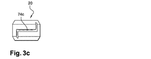
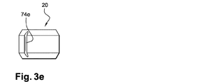
流量低減部材20は、例として図3aから図3fに示されたようなさまざまな形状にすることができる。流量低減部材20は略円筒状であり、外周に周囲凹部を形成する偏向形状部74が形成される。
The
図3aおよび図3bの例では、形状部74は、液体に粘性があまりない場合、好ましくは複数周、円柱20の周囲を走る螺旋溝74a、74bによって画定される。溝74aは、溝74bの断面よりも大きい断面を有し、溝74bよりも粘性の高い液体に適している。
In the example of FIGS. 3 a and 3 b, the shape 74 is defined by
図3cおよび図3dの部材20は、部材20の円筒状部の周囲を走るのではなく、角部、ここでは、直角を成す部分を画定して、そこを流れる液体の圧力を低減する効果のある他のタイプの溝74cおよび74dを示している。任意で、部材20は、周壁の他の部分に溝74cおよび74dと同様の溝を含み、液体流量を増加させてもよい。
The
図3eの部材20は、円筒状部の軸に略平行な直線溝74eを示している。変形形態では、部材20は、部材20の周壁全体にわたって配置される複数の溝74eを有する。別の変形形態では、溝(単数または複数)74eは円柱の軸に対して傾斜される。
The
図3fの部材20は、網目状溝74f〜hを示しており、溝74f〜hが合流する接合部74iを含む。網目状溝は、接合部74iから上流側に位置する上流側溝74f〜gと、接合部74iから下流側に位置する少なくとも1本の下流側溝74hとを有する。変形形態では、網目状溝は、3本以上の上流側溝74f〜gと、2本以上の下流側溝74hと、2つ以上の接合部74iとを有する。
The
次に、図1の装置の動作について説明する。 Next, the operation of the apparatus shown in FIG. 1 will be described.
停止時、すなわち、使用者が容器12を絞っていない時は、弁16は液体遮断配置である、すなわち、弁が支持体14に取り外せないように締結されて、バネ17によって伝えられる圧力の影響を受けて弁に弾性応力がかかるために、弁は面40を支承している。
When stopped, i.e. when the user is not squeezing the
使用者が容器12を絞ると、流体を流すことができる流路のみ(疎水性フィルタ22は液体が流れるのを防ぐ)、すなわち、流量低減流路76に沿って流れる流体に圧力が加わる。流体が流路76に沿って通過する時に、流体の流量はヘッドロス効果によって減少する。その後、この流体は流路32に沿って流れ、次に、キャビティ34に流れ込み、そして流路36に沿って流れる。圧力の影響下で、流体はダイアフラム16を押し上げ、ダイアフラムは液体がダイアフラム16と支承面40との間を流れることができる液体通過配置になり、流体は流路60そしてキャビティ61に流れ込んで、液滴状になる。
When the user squeezes the
流量低減部材20は別個の部品であるので、容器に含まれる液体に応じて形状が変化することがあることは理解されたい。したがって、ハウジング30は、図3aから図3fに示されている形状のような異なる形状の部材20を受承するようになっている。したがって、全てが同じ弁16、同じ支持体14、および同じキャップ18を有するが、部材20が異なるエンドピースを備える組を製造することができる。
It should be understood that since the
エンドピース10は、図1に示されている構造以外の構造、例えば、図2に示されている構造にすることもできる。
The
図2のエンドピースは、空気通過流路42を含まないという点を除けば、図1のエンドピースと同じような機能を有する。この実施形態では、容器12は、好ましくは、非弾性的に変形可能な容器であるので、使用者が容器を絞った後に容器を解放する際に、使用者が絞ることで生じた吸引力を相殺するために空気を通す必要がない。したがって、この例では、ハウジング30は、支持体14の中央に位置しており、流量低減部材20の直径はより大きくなる。
The end piece of FIG. 2 has the same function as the end piece of FIG. 1 except that the
本発明は、上述の実施形態に限定されないことに留意されたい。 It should be noted that the present invention is not limited to the embodiments described above.
Claims (10)
容器に取り付けられるディスペンサエンドピース(10)であって、支持体(14)と液体ディスペンサ弁(16)とを備え、弁はエラストマー材料を含み支持体(14)と協働することで遮断配置および液体通過配置を取ることができるディスペンサエンドピース(10)と、
流量低減流路(76)を画定する液体偏向形状部(74)を備える流量低減部材(20)であって、支持体(14)および弁(16)とは別個の部品である流量低減部材(20)とを備える液体ディスペンサ装置。 A container (12) for storing the dispensed liquid;
A dispenser end piece (10) attached to a container, comprising a support (14) and a liquid dispenser valve (16), wherein the valve comprises an elastomeric material and cooperates with the support (14) to provide a blocking arrangement and A dispenser end piece (10) capable of taking a liquid passing arrangement;
A flow reduction member (20) comprising a liquid deflection feature (74) defining a flow reduction channel (76), wherein the flow reduction member (20) is a separate component from the support (14) and valve (16). 20).
Applications Claiming Priority (2)
| Application Number | Priority Date | Filing Date | Title |
|---|---|---|---|
| FR0956279 | 2009-09-11 | ||
| FR0956279A FR2950037B1 (en) | 2009-09-11 | 2009-09-11 | DEVICE FOR DISTRIBUTING LIQUID |
Related Parent Applications (1)
| Application Number | Title | Priority Date | Filing Date |
|---|---|---|---|
| JP2015086458A Division JP2015177982A (en) | 2009-09-11 | 2015-04-21 | liquid dispenser device |
Publications (2)
| Publication Number | Publication Date |
|---|---|
| JP2018011973A true JP2018011973A (en) | 2018-01-25 |
| JP6549198B2 JP6549198B2 (en) | 2019-07-24 |
Family
ID=42105141
Family Applications (3)
| Application Number | Title | Priority Date | Filing Date |
|---|---|---|---|
| JP2012528427A Pending JP2013504355A (en) | 2009-09-11 | 2010-09-09 | Liquid dispenser device |
| JP2015086458A Pending JP2015177982A (en) | 2009-09-11 | 2015-04-21 | liquid dispenser device |
| JP2017171757A Active JP6549198B2 (en) | 2009-09-11 | 2017-09-07 | Liquid dispenser device |
Family Applications Before (2)
| Application Number | Title | Priority Date | Filing Date |
|---|---|---|---|
| JP2012528427A Pending JP2013504355A (en) | 2009-09-11 | 2010-09-09 | Liquid dispenser device |
| JP2015086458A Pending JP2015177982A (en) | 2009-09-11 | 2015-04-21 | liquid dispenser device |
Country Status (13)
| Country | Link |
|---|---|
| US (1) | US8827124B2 (en) |
| EP (1) | EP2475463B1 (en) |
| JP (3) | JP2013504355A (en) |
| KR (1) | KR20120091071A (en) |
| CN (1) | CN102725073B (en) |
| BR (1) | BR112012005391B1 (en) |
| CA (1) | CA2773988A1 (en) |
| CO (1) | CO6511246A2 (en) |
| FR (1) | FR2950037B1 (en) |
| IN (1) | IN2012DN02151A (en) |
| MX (1) | MX341902B (en) |
| RU (1) | RU2529526C2 (en) |
| WO (1) | WO2011030063A1 (en) |
Families Citing this family (23)
| Publication number | Priority date | Publication date | Assignee | Title |
|---|---|---|---|---|
| FR2937019B1 (en) * | 2008-10-15 | 2012-06-08 | Rexam Pharma La Verpilliere | LIQUID DISPENSING DEVICE WITH SEALING BODY HAVING AN ELASTOMERIC PART |
| GB2474520B (en) * | 2009-10-19 | 2015-08-26 | London & General Packaging Ltd | Spray dispenser |
| WO2012023664A1 (en) * | 2010-08-19 | 2012-02-23 | (주)연우 | Nozzle structure of dispenser pump button |
| KR101278879B1 (en) * | 2012-04-06 | 2013-06-26 | (주)연우 | Tube vessel |
| DE102013202531B3 (en) | 2013-02-16 | 2014-05-28 | Aptar Radolfzell Gmbh | Dispenser for the discharge of liquids |
| JP5803045B2 (en) * | 2013-03-18 | 2015-11-04 | ヤン、ギョンオック | Drug dispenser |
| JP5803046B2 (en) * | 2013-03-18 | 2015-11-04 | ヤン、ギョンオック | Drug dispenser |
| JP5627732B2 (en) * | 2013-04-22 | 2014-11-19 | サーモス株式会社 | Beverage container closure |
| FR3010987B1 (en) * | 2013-09-20 | 2015-10-16 | Rexam Healthcare La Verpillier | DEVICE FOR DISTRIBUTING LIQUID PRODUCT WITHOUT VALVE |
| FR3019475B1 (en) * | 2014-04-08 | 2021-10-15 | Albea Le Treport | DISTRIBUTION MODULE OF A PRODUCT INTENDED TO BE MOUNTED ON A DUCT SUPPLIED UNDER PRESSURE OF THE SAID PRODUCT |
| US10392166B2 (en) | 2015-03-19 | 2019-08-27 | Silgan Dispensing Systems Slatersville Llc | Squirt dispensing closure for liquid drink concentrate |
| ITUB20150884A1 (en) * | 2015-05-25 | 2016-11-25 | Arno Drechsel | PRESSURE REGULATING DEVICE FOR A LIQUID |
| US10207844B2 (en) | 2015-08-26 | 2019-02-19 | Berry Plastics Corporation | Dropper |
| CA3001533A1 (en) | 2015-11-05 | 2017-05-11 | Eiken Kagaku Kabushiki Kaisha | Discharge member with filter |
| DE102016202078B4 (en) * | 2016-02-11 | 2017-08-24 | Siemens Aktiengesellschaft | Covering device for covering a pipe opening of a drinking water pipe |
| US11760193B2 (en) * | 2017-09-29 | 2023-09-19 | Illinois Tool Works Inc. | Reservoir tank cap closure indicators |
| FR3080844B1 (en) * | 2018-05-07 | 2020-06-05 | Horus Pharma | PACKAGING AND DISPENSING DEVICE OF A PRODUCT WITH BOTTLE AND METERING CAP WITH FILTER |
| KR101897443B1 (en) * | 2018-07-09 | 2018-09-12 | 양경옥 | Medicant dispenser for the prevention infiltration frombacteria |
| US20210308705A1 (en) * | 2018-07-25 | 2021-10-07 | Rieke Llc | Spraying dispenser with leak-proof vent |
| MX2021011724A (en) * | 2019-03-28 | 2021-10-22 | Tearclear Corp | Devices and methods for flow control of ophthalmic formulations. |
| CN110654703B (en) * | 2019-09-27 | 2020-11-24 | 裴学华 | Portable water ware |
| WO2022005310A1 (en) * | 2020-07-01 | 2022-01-06 | Gamboa Burgos Alejandro | Liquid-dispensing device with droplet non-return mechanism, air filter and multifunction membrane valve |
| EP4186509A1 (en) | 2021-11-26 | 2023-05-31 | Alpha Cognition Inc. | Alpha-1062 for treating traumatic brain injury |
Citations (14)
| Publication number | Priority date | Publication date | Assignee | Title |
|---|---|---|---|---|
| JPS6160457A (en) * | 1984-08-24 | 1986-03-28 | キヤニヨン株式会社 | Toggle type pressing type dispenser |
| JPH02180659A (en) * | 1988-10-07 | 1990-07-13 | Ryder Internatl Corp | Nozzle mechanism for distributing liquid |
| WO1995030491A1 (en) * | 1994-05-04 | 1995-11-16 | Precept Design Consultants Plc | Apparatus and method for spray and other dispensing |
| US5605257A (en) * | 1996-03-04 | 1997-02-25 | Beard; Walter C. | Sterile liquid squeeze-bottle-type dispenser |
| JPH09507412A (en) * | 1994-01-10 | 1997-07-29 | ベスパック・パブリック・リミテッド・カンパニー | Aseptic liquid dispenser |
| JP2003040309A (en) * | 2001-07-31 | 2003-02-13 | Yoshino Kogyosho Co Ltd | Vessel for spouting liquid of fixed quantity |
| JP2003221052A (en) * | 2002-01-29 | 2003-08-05 | Daipura Kk | Liquid container |
| WO2004069679A1 (en) * | 2003-02-07 | 2004-08-19 | Hoffmann Neopac Ag | Drop dispensing with insert for optimizing the dosing precision of liquids |
| JP2005082233A (en) * | 2003-09-11 | 2005-03-31 | Gc Corp | Liquid storage vessel |
| JP2005320006A (en) * | 2002-05-08 | 2005-11-17 | Hagy Giken Kk | Discharge nozzle having content backflow preventive function, and liquid container having discharge nozzle |
| JP2007136205A (en) * | 2005-11-21 | 2007-06-07 | Ing Erich Pfeiffer Gmbh & Co Kg | Dispenser for apportionment of medium, and assembly for apportionment |
| JP2007204141A (en) * | 2006-02-06 | 2007-08-16 | Shinko Chemical Co Ltd | Inside stopper of chemical receptacle |
| JP2007245142A (en) * | 2006-03-13 | 2007-09-27 | Ing Erich Pfeiffer Gmbh & Co Kg | Discharge apparatus for flowing substance |
| JP2007530376A (en) * | 2004-03-26 | 2007-11-01 | シークイスト クロージャーズ フォーリン、 インコーポレイテッド | Product discharge valve |
Family Cites Families (15)
| Publication number | Priority date | Publication date | Assignee | Title |
|---|---|---|---|---|
| US1759081A (en) * | 1929-04-06 | 1930-05-20 | John K Anderson | Valve construction |
| US2759643A (en) * | 1951-02-01 | 1956-08-21 | Orga Ab | Container closure |
| GB8825632D0 (en) * | 1988-11-02 | 1988-12-07 | Bespak Plc | Dispensing apparatus for pressurised dispensing containers |
| US5154325A (en) * | 1991-01-09 | 1992-10-13 | Ryder International Corporation | Solution delivery nozzle and system with antimicrobial features |
| US5676289A (en) * | 1996-04-04 | 1997-10-14 | Aptargroup, Inc. | Valve-controlled dispensing closure with dispersion baffle |
| RU2162051C1 (en) * | 1999-07-13 | 2001-01-20 | ООО "НПП Аквалитан" | Device for dispensing of liquid under pressure (design versions) |
| FR2824620B1 (en) * | 2001-05-10 | 2004-09-24 | Air Liquide | VALVE-REGULATOR PROVIDED WITH A CONNECTION SUITABLE FOR CONNECTING A USER SOCKET |
| KR20040023734A (en) * | 2001-08-09 | 2004-03-18 | 타다시 하기하라 | Container with discharge flow velocity mechanism |
| EP1520797A4 (en) * | 2002-05-08 | 2006-07-05 | Hagy Tech Co Ltd | Discharge nozzle with function for preventing backflow of content and liquid container comprising discharge nozzle |
| WO2004011345A1 (en) * | 2002-07-31 | 2004-02-05 | Otsuka Pharmaceutical Co., Ltd. | Discharge member and container provided with the same |
| ITVI20050053A1 (en) * | 2005-02-25 | 2006-08-26 | Taplast Spa | DEVICE FOR THE DELIVERY OF GAS-LIQUID MIXTURES |
| US20070221686A1 (en) * | 2006-03-27 | 2007-09-27 | Taesung Industrial Co., Ltd. | Liquid pump dispenser |
| US7637402B2 (en) * | 2006-09-01 | 2009-12-29 | Polytop Corporation | Dispensing cap with center channel and helical flow profile |
| US7850050B2 (en) * | 2006-09-22 | 2010-12-14 | Mcneil-Ppc, Inc. | Liquid dispensing apparatus and device |
| CN201016086Y (en) * | 2007-03-09 | 2008-02-06 | 丁慧琳 | Liquid separated charging device |
-
2009
- 2009-09-11 FR FR0956279A patent/FR2950037B1/en not_active Expired - Fee Related
-
2010
- 2010-09-09 CA CA2773988A patent/CA2773988A1/en not_active Abandoned
- 2010-09-09 JP JP2012528427A patent/JP2013504355A/en active Pending
- 2010-09-09 EP EP10768999.4A patent/EP2475463B1/en active Active
- 2010-09-09 MX MX2012003040A patent/MX341902B/en active IP Right Grant
- 2010-09-09 BR BR112012005391-4A patent/BR112012005391B1/en active IP Right Grant
- 2010-09-09 CN CN201080046490.9A patent/CN102725073B/en active Active
- 2010-09-09 WO PCT/FR2010/051878 patent/WO2011030063A1/en active Application Filing
- 2010-09-09 RU RU2012114152/05A patent/RU2529526C2/en not_active IP Right Cessation
- 2010-09-09 IN IN2151DEN2012 patent/IN2012DN02151A/en unknown
- 2010-09-09 KR KR1020127009295A patent/KR20120091071A/en not_active Application Discontinuation
-
2012
- 2012-03-12 US US13/418,146 patent/US8827124B2/en active Active
- 2012-03-15 CO CO12045401A patent/CO6511246A2/en active IP Right Grant
-
2015
- 2015-04-21 JP JP2015086458A patent/JP2015177982A/en active Pending
-
2017
- 2017-09-07 JP JP2017171757A patent/JP6549198B2/en active Active
Patent Citations (14)
| Publication number | Priority date | Publication date | Assignee | Title |
|---|---|---|---|---|
| JPS6160457A (en) * | 1984-08-24 | 1986-03-28 | キヤニヨン株式会社 | Toggle type pressing type dispenser |
| JPH02180659A (en) * | 1988-10-07 | 1990-07-13 | Ryder Internatl Corp | Nozzle mechanism for distributing liquid |
| JPH09507412A (en) * | 1994-01-10 | 1997-07-29 | ベスパック・パブリック・リミテッド・カンパニー | Aseptic liquid dispenser |
| WO1995030491A1 (en) * | 1994-05-04 | 1995-11-16 | Precept Design Consultants Plc | Apparatus and method for spray and other dispensing |
| US5605257A (en) * | 1996-03-04 | 1997-02-25 | Beard; Walter C. | Sterile liquid squeeze-bottle-type dispenser |
| JP2003040309A (en) * | 2001-07-31 | 2003-02-13 | Yoshino Kogyosho Co Ltd | Vessel for spouting liquid of fixed quantity |
| JP2003221052A (en) * | 2002-01-29 | 2003-08-05 | Daipura Kk | Liquid container |
| JP2005320006A (en) * | 2002-05-08 | 2005-11-17 | Hagy Giken Kk | Discharge nozzle having content backflow preventive function, and liquid container having discharge nozzle |
| WO2004069679A1 (en) * | 2003-02-07 | 2004-08-19 | Hoffmann Neopac Ag | Drop dispensing with insert for optimizing the dosing precision of liquids |
| JP2005082233A (en) * | 2003-09-11 | 2005-03-31 | Gc Corp | Liquid storage vessel |
| JP2007530376A (en) * | 2004-03-26 | 2007-11-01 | シークイスト クロージャーズ フォーリン、 インコーポレイテッド | Product discharge valve |
| JP2007136205A (en) * | 2005-11-21 | 2007-06-07 | Ing Erich Pfeiffer Gmbh & Co Kg | Dispenser for apportionment of medium, and assembly for apportionment |
| JP2007204141A (en) * | 2006-02-06 | 2007-08-16 | Shinko Chemical Co Ltd | Inside stopper of chemical receptacle |
| JP2007245142A (en) * | 2006-03-13 | 2007-09-27 | Ing Erich Pfeiffer Gmbh & Co Kg | Discharge apparatus for flowing substance |
Also Published As
| Publication number | Publication date |
|---|---|
| MX2012003040A (en) | 2012-10-03 |
| CA2773988A1 (en) | 2011-03-17 |
| EP2475463A1 (en) | 2012-07-18 |
| WO2011030063A1 (en) | 2011-03-17 |
| RU2012114152A (en) | 2013-10-20 |
| CN102725073A (en) | 2012-10-10 |
| CO6511246A2 (en) | 2012-08-31 |
| MX341902B (en) | 2016-09-06 |
| JP2013504355A (en) | 2013-02-07 |
| FR2950037A1 (en) | 2011-03-18 |
| CN102725073B (en) | 2015-11-25 |
| US8827124B2 (en) | 2014-09-09 |
| EP2475463B1 (en) | 2013-08-14 |
| FR2950037B1 (en) | 2011-12-16 |
| RU2529526C2 (en) | 2014-09-27 |
| IN2012DN02151A (en) | 2015-08-07 |
| JP6549198B2 (en) | 2019-07-24 |
| US20120305599A1 (en) | 2012-12-06 |
| BR112012005391B1 (en) | 2021-01-05 |
| KR20120091071A (en) | 2012-08-17 |
| BR112012005391A2 (en) | 2016-04-05 |
| JP2015177982A (en) | 2015-10-08 |
Similar Documents
| Publication | Publication Date | Title |
|---|---|---|
| JP2018011973A (en) | Liquid dispenser device | |
| JP5739890B2 (en) | Liquid dispenser device and assembly method thereof | |
| ES2876003T3 (en) | High flow aerosol valve | |
| KR102110129B1 (en) | Cap | |
| JP5331689B2 (en) | Bottles for storing liquids, especially pharmaceutical products | |
| US7025233B2 (en) | Fluid discharge pump for discharging fluid stored inside fluid storing portion | |
| EP2764244B1 (en) | Fluid dispensing system | |
| CN108474489B (en) | Check valve structure, nozzle member using same, and squeeze container | |
| JP6860349B2 (en) | A method of packaging and distributing products with a dosing nozzle | |
| EP1561515A2 (en) | Fluid-dispensing pump and container provided therewith | |
| US20040261868A1 (en) | Collapsible dispensing system | |
| JP7398608B2 (en) | Device for packaging and administering products, having a vial and a dosing mouthpiece with a filter | |
| CN104058180B (en) | Medicament dispenser | |
| KR20040101181A (en) | Dispensing container | |
| JP2011527214A (en) | Fluid dispenser pump | |
| JPWO2006011473A1 (en) | Squeeze bottle and eye drop container using the same | |
| CN109070115A (en) | Seal check-valves | |
| JP7233431B2 (en) | Fluid ejector | |
| ES2720248T3 (en) | Liquid dispenser with valve | |
| JP4331952B2 (en) | Valve mechanism | |
| TW201225948A (en) | A liquid dispenser device | |
| WO2017212851A1 (en) | Flow rate control device, emitter, and drip irrigation tube | |
| JP6710602B2 (en) | Emitter and drip irrigation tubes | |
| JP2014516331A (en) | Liquid dispensing device with flow reducing member | |
| JP2008260539A (en) | Piston and fluid container using this piston |
Legal Events
| Date | Code | Title | Description |
|---|---|---|---|
| A131 | Notification of reasons for refusal |
Free format text: JAPANESE INTERMEDIATE CODE: A131 Effective date: 20180703 |
|
| A977 | Report on retrieval |
Free format text: JAPANESE INTERMEDIATE CODE: A971007 Effective date: 20180629 |
|
| A131 | Notification of reasons for refusal |
Free format text: JAPANESE INTERMEDIATE CODE: A131 Effective date: 20190212 |
|
| A521 | Request for written amendment filed |
Free format text: JAPANESE INTERMEDIATE CODE: A523 Effective date: 20190508 |
|
| TRDD | Decision of grant or rejection written | ||
| A01 | Written decision to grant a patent or to grant a registration (utility model) |
Free format text: JAPANESE INTERMEDIATE CODE: A01 Effective date: 20190528 |
|
| A61 | First payment of annual fees (during grant procedure) |
Free format text: JAPANESE INTERMEDIATE CODE: A61 Effective date: 20190626 |
|
| R150 | Certificate of patent or registration of utility model |
Ref document number: 6549198 Country of ref document: JP Free format text: JAPANESE INTERMEDIATE CODE: R150 |
|
| S533 | Written request for registration of change of name |
Free format text: JAPANESE INTERMEDIATE CODE: R313533 |
|
| R350 | Written notification of registration of transfer |
Free format text: JAPANESE INTERMEDIATE CODE: R350 |
|
| R250 | Receipt of annual fees |
Free format text: JAPANESE INTERMEDIATE CODE: R250 |
|
| R250 | Receipt of annual fees |
Free format text: JAPANESE INTERMEDIATE CODE: R250 |