EP3110000A1 - Control device - Google Patents
Control device Download PDFInfo
- Publication number
- EP3110000A1 EP3110000A1 EP14882288.5A EP14882288A EP3110000A1 EP 3110000 A1 EP3110000 A1 EP 3110000A1 EP 14882288 A EP14882288 A EP 14882288A EP 3110000 A1 EP3110000 A1 EP 3110000A1
- Authority
- EP
- European Patent Office
- Prior art keywords
- loss
- motor
- inverter
- electric motor
- stator
- Prior art date
- Legal status (The legal status is an assumption and is not a legal conclusion. Google has not performed a legal analysis and makes no representation as to the accuracy of the status listed.)
- Granted
Links
Images





Classifications
-
- H—ELECTRICITY
- H02—GENERATION; CONVERSION OR DISTRIBUTION OF ELECTRIC POWER
- H02P—CONTROL OR REGULATION OF ELECTRIC MOTORS, ELECTRIC GENERATORS OR DYNAMO-ELECTRIC CONVERTERS; CONTROLLING TRANSFORMERS, REACTORS OR CHOKE COILS
- H02P29/00—Arrangements for regulating or controlling electric motors, appropriate for both AC and DC motors
- H02P29/60—Controlling or determining the temperature of the motor or of the drive
-
- H—ELECTRICITY
- H02—GENERATION; CONVERSION OR DISTRIBUTION OF ELECTRIC POWER
- H02P—CONTROL OR REGULATION OF ELECTRIC MOTORS, ELECTRIC GENERATORS OR DYNAMO-ELECTRIC CONVERTERS; CONTROLLING TRANSFORMERS, REACTORS OR CHOKE COILS
- H02P27/00—Arrangements or methods for the control of AC motors characterised by the kind of supply voltage
- H02P27/04—Arrangements or methods for the control of AC motors characterised by the kind of supply voltage using variable-frequency supply voltage, e.g. inverter or converter supply voltage
- H02P27/06—Arrangements or methods for the control of AC motors characterised by the kind of supply voltage using variable-frequency supply voltage, e.g. inverter or converter supply voltage using DC to AC converters or inverters
Definitions
- the present disclosure relates to a control device for driving an electric motor.
- a control device of an induction electric motor that is the power source of an electric vehicle converts a run command, ordering output from the induction electric motor, into a control signal that is output to an inverter main circuit.
- the inverter main circuit converts inputted DC electric power into variable voltage-variable frequency AC electric power and drives the induction electric motor.
- the electric power supplied to the electric motor in addition to being converted into shaft output of the electric motor, is converted into iron loss and copper loss, which are internal losses of the electric motor. These iron and copper losses become thermal energy and cause a rise of temperature of the electric motor.
- Control devices for electric motors also referred to below simply as “motors” often lack over-temperature protection for the motor due to omission of a temperature sensor due to difficulty of placement of the temperature sensor in the electric motors, as well as high cost and the like.
- over-temperature protection When over-temperature protection is provided, protective sensing and the like occurs when the motor current effective value exceeds a threshold for at least a fixed time period, or when an estimated motor temperature or a corresponding equivalent loss exceeds a threshold value.
- a main electric motor is determined to have a temperature state exceeding a standard state based on a motor current effective value.
- temperature of the other windings is estimated based on temperature detected by a temperature sensor arranged at a position for detection of temperature of one winding among windings supplying three-phase AC current.
- Temperature is inferred from resistance value by use of the fact that resistance value of the winding is proportional to its temperature.
- the electric motor protective device of Patent Literature 3 uses voltage and current value of each frequency as input data for calculation of impedance, and calculates temperatures of the electric motor stator and windings of rotor based on the resistance component of impedance.
- motor heating-protection device of Patent Literature 4 motor applied voltage, rotation rate and motor current are used to calculate winding resistance, and a winding temperature ⁇ is calculated based on the winding resistance.
- each value of coil current, voltage across the coil terminals and rotor rotation rate is used to calculate a coil line-to-line resistance value.
- the motor in the case of a motor provided with over-temperature protection, the motor is protected by stoppage of a control device and the like when the motor current effective value exceeds a threshold for at least a fixed time period and the like, or when an estimated motor temperature or a corresponding equivalent loss exceeds a threshold value.
- the motor losses when a motor is controlled using an inverter, include losses due to fundamental waves and losses due to harmonic waves.
- losses due to harmonic waves are greatly affected by motor voltage, inverter output frequency, inverter carrier frequency and pulse mode.
- motor temperature cannot be accurately estimated. Accuracy is poor for a method that infers temperatures of other windings based on the temperature of a single winding, or that estimates temperature based on a resistance value.
- the objective of the present disclosure is to improve accuracy of over-temperature protection of an electric motor.
- the control device of the present disclosure is a control device to control an inverter for driving an electric motor; the control device acquires a DC voltage input to the inverter, an output voltage of the inverter, a motor amperage of current flowing through the electric motor, and a motor frequency indicating a rotation rate of the electric motor; and the control device uses a loss calculator to calculate a stator loss and a rotor loss including fundamental losses and harmonic losses of the electric motor, based on at least one of the DC voltage, the output voltage of the inverter, the motor amperage, and the motor frequencies. Also the control device is equipped with a controller to output an actual control value for control of the inverter, based on the output voltage of the inverter, the stator loss and the rotor loss.
- the accuracy of over-temperature protection of an electric motor is improved by calculating a stator loss and a rotor loss including fundamental losses and harmonic losses of the electric motor, and an actual control value for controlling an inverter is output based on the output voltage of the inverter, the stator losses and the rotor losses.
- FIG. 1 is a diagram showing configuration of a control device according to Embodiment 1 of the present disclosure.
- an electric motor 1 is an induction electric motor.
- An inverter main circuit 2 includes a filter capacitor 11 and semiconductor switching elements Su, Sx, Sv, Sy, Sw and Sz. Based on a main circuit operation command GS output from an electric power conversion circuit controller 4, the inverter main circuit 2, by ON-OFF control of the switching elements Su to Sz, converts DC electric power supplied from a pantograph 12 to variable voltage-variable frequency three-phase AC current, and supplies the three-phase AC current to the electric motor 1.
- the control device 7 includes the electric power conversion circuit controller 4, a motor loss estimator 5 and a motor overload detector 6.
- An operation command generator 3 outputs to the electric power conversion circuit controller 4 a run command A such as a command for powering or braking, and a strength thereof and the like.
- the run command A includes an output voltage of the inverter main circuit 2.
- Motor voltage increases with the inverter frequency, and is saturated at a voltage that depends on the DC voltage input to the inverter.
- the magnitude of the motor current is determined by the output required for the electric motor.
- the carrier frequency is set in a range of several hundreds of Hz to several thousands of Hz, and switching operation of the inverter main circuit is performed by triangular wave comparison out of synchrony with the modulation wave.
- This condition is referred to as "asynchronous mode”.
- the carrier frequency is synchronized with the modulation wave, and the carrier frequency is set such that the pulse count during the inverter output voltage half cycle is at least 3 pulses, so as to perform switching operation of the inverter main circuit.
- This condition is referred to as "synchronous multi-pulse mode”.
- the carrier frequency and the inverter frequency are synchronized so that the motor voltage becomes maximum, the pulse count during the inverter output voltage half cycle is set to one, and switching operation of the inverter main circuit is performed. This condition is termed "synchronous one-pulse mode".
- the carrier frequency and the pulse mode are made variable according to the inverter frequency or motor voltage.
- a harmonic primary copper loss and a harmonic secondary copper loss are large and lead to increased motor loss.
- primary copper loss refers to ohmic loss generated in a primary winding resistance.
- the “Fundamental primary copper loss” refers to the portion generated by the fundamental of the inverter frequency.
- the “secondary copper loss” is the ohmic loss generated in the secondary winding.
- the “harmonic secondary copper loss” refers to the portion generated by the harmonics of the inverter frequency.
- the “iron losses” are hysteresis loss and eddy current loss occurring mainly in the iron core.
- the “fundamental iron loss” refers to the portion generated by the fundamental of the inverter frequency
- the “harmonic iron loss” refers to the portion generated by the harmonics of the inverter frequency.
- the motor current effective value used for temperature evaluation of the motor according to the conventional technology indicates only the fundamental primary copper loss and the fundamental secondary copper loss. By only using the motor current effective value, iron and surface losses cannot be considered, and this results in underestimation of motor losses.
- a run command (output voltage of the inverter main circuit 2) A from the operation command generator 3 is received as input by the control device 7 of FIG. 1 .
- the control device 7 acquires the DC voltage EFC and the motor current Im from the inverter main circuit 2.
- the motor frequency FM is acquired from a rotation detector 8 attached to the electric motor 1.
- the DC voltage EFC is detected by a voltage detector 10.
- the motor current Im is detected by a current detector 9.
- the control device 7 calculates the stator loss QS and rotor loss QR, each including the fundamental losses and harmonic losses of the electric motor 1. Thereafter, based on the run command A, stator loss QS and rotor loss QR, the main circuit operation command GS is output for control of the inverter main circuit 2.
- FIG. 2 is a block diagram showing an example configuration of the electric power conversion circuit controller according to Embodiment 1.
- the electric power conversion circuit controller 4 calculates a slip frequency fs using the current command generator 4a and calculates the desired torque to be output by the electric motor 1. Thereafter, an electric current command IMR and a magnetic flux command F2R for the output of the inverter main circuit 2 are output to the voltage command generator 4b. Moreover, the slip frequency fs is output to an inverter frequency generator 4c.
- the inverter frequency generator 4c generates as output an inverter frequency finv based on the run command A, motor frequency FM and slip frequency fs, and sends the output to the motor loss estimator 5 ( FIG. 1 ). Moreover, the inverter frequency finv is output to the voltage command generator 4b.
- the voltage command generator 4b outputs a voltage command Vm and a pulse mode PM to the main circuit operation command generator 4d based on the electric current command IMR and magnetic flux command F2R output from the current command generator 4a, the DC voltage EFC supplied from the pantograph 12, the motor current Im flowing through the electric motor 1, and the inverter frequency finv output from the inverter frequency generator 4c.
- a modulation wave generator 4da is used to generate a modulation wave VREF, based on the voltage command Vm and the pulse mode PM
- a carrier wave generator 4db is used to generate a carrier wave CAR.
- a main circuit operation command GS is output to a switching element.
- a switch 4e is used to make the main circuit operation command GS inoperable and the switching element is set to the OFF state.
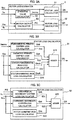
- FIG. 3A is a diagram showing configuration of a motor loss estimator according to Embodiment 1.
- the motor loss estimator 5 based on the motor current Im output by the electric power conversion circuit controller 4, uses an effective value calculator 50 to calculate a motor current effective value Imrms.
- a motor output calculator 53 Based on the motor current Im and the voltage command Vm output from the electric power conversion circuit controller 4, a motor output calculator 53 calculates a motor output PO.
- a stator loss QS is calculated by a stator loss calculator 51 and a rotor loss QR is calculated by a rotor loss calculator 52, and these calculated values are output to a motor overload detector 6 ( FIG. 1 ).
- FIG. 3B is a diagram showing configuration of the stator loss calculator according to Embodiment 1.
- the stator loss calculator 51 receives as input the inverter frequency finv and motor current effective value Imrms, and a fundamental primary copper loss calculator 511 calculates a fundamental primary copper loss Qsb based on the motor current effective value. Thereafter, based on the inverter frequency finv, a harmonic primary copper loss Qsh is calculated by a harmonic primary copper loss calculator 512, a stator fundamental iron loss Qssb is calculated by a stator fundamental iron loss calculator 513, a stator harmonic iron loss Qssh is calculated by a stator harmonic iron loss calculator 514, and each of these values is output to an adder 515.
- the adder 515 adds each of the losses and outputs the sum to the motor overload detector 6 as the stator loss QS.
- FIG. 3C is a diagram showing configuration of the rotor loss calculator of Embodiment 1.
- the rotor loss calculator 52 receives as input the motor output PO, slip frequency fs and inverter frequency finv, and uses a fundamental secondary copper loss calculator 521 to calculate a fundamental secondary copper loss Qrb.
- a harmonic secondary copper loss calculator 522 calculates a harmonic secondary copper loss Qrh
- rotor harmonic iron loss calculator 523 calculates a stator harmonic iron loss Qrs, and these values are each output to an adder 525.
- the adder 525 adds each of the losses and outputs the sum to the motor overload detector 6 as the rotor loss QR.
- Each block of the loss calculations is described below.
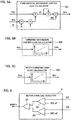
- FIG. 4A is a diagram showing configuration of the fundamental primary copper loss calculator according to Embodiment 1.
- the fundamental primary copper loss calculator 511 calculates the product of multiplication of a primary resistance R1 by the square of the motor current effective value Imrsm, and outputs the fundamental primary copper loss Qsb.
- FIG. 4B shows configuration of the harmonic primary copper loss calculator
- FIG. 4C shows configuration of the stator fundamental iron loss calculator
- FIG. 4D shows configuration of the stator harmonic iron loss calculator.
- the harmonic primary copper loss Qsh, stator fundamental iron loss Qssb and stator harmonic iron loss Qssh depend on the inverter frequency finv, voltage command Vm and pulse mode PM.
- each of these losses rather than changing according to the run command A like the motor current Im, can be taken to be previously known information, with the inverter frequency finv plotted along the horizontal axis.
- each of the losses versus the inverter frequency finv can be defined by a loss table to calculate the harmonic primary copper loss Qsh, stator fundamental iron loss Qssb and stator harmonic iron loss Qssh according to the horizontally-plotted inverter frequency finv.
- FIG. 5A is a diagram showing configuration of the fundamental secondary copper loss calculator according to Embodiment 1.
- the fundamental secondary copper loss calculator 521 uses the motor output PO to calculate a rotor current IR. Then the fundamental secondary copper loss calculator 521 calculates a product of a secondary resistance R2 times the square of the rotor current IR, and outputs the result as the fundamental secondary copper loss Qrb.
- FIG. 5B shows configuration of the harmonic secondary copper loss calculator
- FIG. 5C shows configuration of the rotor harmonic iron loss calculator.
- the losses calculated by the harmonic secondary copper loss calculator 522 and rotor harmonic iron loss calculator 523, as described above, depend on the inverter frequency finv, voltage command Vm and pulse mode PM. However, unlike the motor current Im, these losses do not change due to the run command A, and each of these losses can be set as previously known information versus the horizontally-plotted inverter frequency finv.
- each of the losses versus the inverter frequency finv can be defined by a loss table and can be output as the harmonic secondary copper loss Qrh and rotor harmonic iron loss Qrs according to the inverter frequency finv.
- FIG. 6 is a diagram showing configuration of the motor overload detector according to Embodiment 1.
- the motor overload detector 6 uses a comparator 61 to compare the estimated stator loss QS, output from the motor loss estimator 5, to a stator overload detection setting signal QS_ref, and uses a comparator 62 to compare the estimated rotor loss QR to a rotor overload detection setting signal QR_ref.
- a logical OR calculator 63 outputs a motor overload detection signal MMTH to the electric power conversion circuit controller 4. Via the switch 4e as shown in FIG. 2 , the motor overload detection signal MMTH forbids operation of the main circuit operation command GS and turns OFF the switching elements Su to Sz of the inverter main circuit 2.
- Embodiment 1 when the stator loss QS or the rotor loss QR exceeds their respective setting level, the motor overload detection signal MMTH is output, and operation of the inverter main circuit is stopped, thereby preventing motor burnout. Stopping of current to the electric motor 1 is not required for the stopping of motor burnout. For example, a configuration can be used in which the current flowing through the electric motor 1 is suppressed, or the run command A for determining size of the motor current is restricted.
- the main circuit operation command (actual control value) for controlling the inverter is output based on the fundamental losses and harmonic losses included in each of the stator loss and rotor loss, and thus accuracy of electric motor over-temperature protection can be improved. Furthermore, not only an induction electric motor but also a synchronous electric motor is applicable to be used as the electric motor 1.
- a plurality of electric motors drive one load.
- a plurality of electric motors may drive one assembly of electric vehicles.
- the inverter main circuit is provided for each of the electric motors.
- the control device Based on the run command A, stator loss QS and rotor loss QR for each electric motor, the control device outputs the main circuit operation command GS for controlling the inverter main circuits of each of the electric motors.
- any of the stator loss QS and the rotor loss QR of the electric motor exceed the respective detection setting signal level
- at least part of a difference between the run command A for the electric motor and the output of the electric motor according to the main circuit operation command GS is added to an adjustment command value for addition to the run command for the electric motor for which the stator loss QA and the rotor loss QR do not exceed the detection setting signal levels.
- the main circuit operation command GS for controlling the inverter is output to the electric motor for which this adjustment command value was added, based on the adjustment command value, stator loss QS and rotor loss QR.
- FIG. 7 is a diagram showing configuration of the control device according to Embodiment 2 of the present disclosure.
- Embodiment 2 an example is described of a configuration using two electric motors 21 and 26.
- An inverter main circuit 22 is provided corresponding to an electric motor 21, and an inverter main circuit 27 is provided corresponding to an electric motor 26.
- the control device 35 has basically the same configuration as that of Embodiment 1, as described above, according to the resultant 2-group configuration of the inverter main circuits 22 and 27, the I/O signals between the control device 35 and the inverter main circuits 22 and 27 are for 2 groups.
- the control device 35 receives as input the run command A from the operation command generator 31. Respective values for the run command A may be input for each of the electric motors 21 and 26, or alternatively, one value may be input, and then distributed by the control device 35 for each of the electric motors 21 and 26.
- the control device 35 acquires a motor current Im1 and a DC voltage EFC1 from the inverter main circuit 22, and acquires a motor current Im2 and a DC voltage EFC2 from the inverter main circuit 27.
- a motor frequency FM1 is acquired from a rotation detector 23 attached to the electric motor 21, and a motor frequency FM2 is acquired from a rotation detector 28 attached to the electric motor 26.
- the control device 35 calculates for the electric motor 21 a stator loss QS1 and a rotor loss QR1, each including the fundamental losses and harmonic losses, and based on the DC voltage EFC2, run command A, motor current Im2 and motor frequency FM2 for the electric motor 26, calculates for the electric motor 26 a stator loss QS2 and a rotor loss QR2, each including the fundamental losses and harmonic losses.
- a main circuit operation command GS1 is output for controlling the inverter main circuit 22; and based on the run command A, stator loss QS2 and rotor loss QR2, a main circuit operation command GS2 is output for controlling the inverter main circuit 27.
- the motor loss estimator 33 and the motor overload detector 34 are internally configured as motor loss estimators and motor overload detectors that are separately provided for the electric motors 21 and 26, and are identical to those of Embodiment 1, although internal logic is the same for the motor loss estimators and the motor overload detectors.
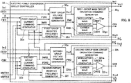
- FIG. 8 is a block diagram showing an example configuration of the electric power conversion circuit controller according to Embodiment 2.
- the motor overload detection signal MMTH1 for the electric motor 21 generated by the motor overload detector 34 is received as input by a first-group current command generator 32a
- the motor overload detection signal MMTH2 for the electric motor 26 generated by the motor overload detector 34 is received as input by a second-group current command generator 32b.
- the first-group electric current command IMR1 is input to the second-group current command generator 32b
- the second-group electric current command IMR2 is input to the first-group current command generator 32a, resulting in a configuration that enables the first group and the second group to monitor the motor control state of the other group.
- FIG. 9 is a diagram showing transitioning of electric current commands when first-group motor over-temperature sensing occurs according to Embodiment 2.
- Embodiment 1 a configuration is used such that, when motor overload is detected, the inverter main circuit is stopped, or current flowing through the electric motor is suppressed, or the run command A for determination of size of the current is restricted.
- Embodiment 2 as shown in FIG. 9 , for example when a motor overload is detected at the first-group side, the first-group electric current command is narrowed by a first-group current reduction IS1 within a range that avoids motor overload.
- the second-group electric current command IMR2 is increased by a second-group current increase amount IS2 portion equivalent to the first-group current reduction IS1 after input of the first-group motor load MMTH1.
- first-group current command generator 32a and the second-group current generator 32b stability of running can be secured without loss of performance as one assembly of electric vehicles, for example, in which one load is driven by the electric motors 21 and 26.
- the second-group increase amount IS2 is preferably less than or equal to the first-group reduction IS1, and of course, the second-group increase amount IS2 not being equal to the first-group reduction IS1 is permissible.
Landscapes
- Engineering & Computer Science (AREA)
- Power Engineering (AREA)
- Control Of Ac Motors In General (AREA)
Abstract
Description
- The present disclosure relates to a control device for driving an electric motor.
- A control device of an induction electric motor that is the power source of an electric vehicle converts a run command, ordering output from the induction electric motor, into a control signal that is output to an inverter main circuit. The inverter main circuit converts inputted DC electric power into variable voltage-variable frequency AC electric power and drives the induction electric motor.
- The electric power supplied to the electric motor, in addition to being converted into shaft output of the electric motor, is converted into iron loss and copper loss, which are internal losses of the electric motor. These iron and copper losses become thermal energy and cause a rise of temperature of the electric motor.
- Control devices for electric motors (also referred to below simply as "motors") often lack over-temperature protection for the motor due to omission of a temperature sensor due to difficulty of placement of the temperature sensor in the electric motors, as well as high cost and the like. When over-temperature protection is provided, protective sensing and the like occurs when the motor current effective value exceeds a threshold for at least a fixed time period, or when an estimated motor temperature or a corresponding equivalent loss exceeds a threshold value. For example, according to Patent Literature 1, a main electric motor is determined to have a temperature state exceeding a standard state based on a motor current effective value.
- According to the electric motor control method of
Patent Literature 2, temperature of the other windings is estimated based on temperature detected by a temperature sensor arranged at a position for detection of temperature of one winding among windings supplying three-phase AC current. - Temperature is inferred from resistance value by use of the fact that resistance value of the winding is proportional to its temperature. The electric motor protective device of
Patent Literature 3 uses voltage and current value of each frequency as input data for calculation of impedance, and calculates temperatures of the electric motor stator and windings of rotor based on the resistance component of impedance. According to the motor heating-protection device of Patent Literature 4, motor applied voltage, rotation rate and motor current are used to calculate winding resistance, and a winding temperature θ is calculated based on the winding resistance. Moreover, according to the temperature-change sensing method for a rotary motor ofPatent Literature 5, each value of coil current, voltage across the coil terminals and rotor rotation rate is used to calculate a coil line-to-line resistance value. -
- Patent Literature 1: Unexamined Japanese Patent Application Kokai Publication No.
H10-336805 - Patent Literature 2: Unexamined Japanese Patent Application Kokai Publication No.
2001-268989 - Patent Literature 3: Unexamined Japanese Patent Application Kokai Publication No.
H3-128692 - Patent Literature 4: Unexamined Japanese Patent Application Kokai Publication No.
H11-289790 - Patent Literature 5: Unexamined Japanese Patent Application Kokai Publication No.
2007-315994 - In the above described manner, in the case of a motor provided with over-temperature protection, the motor is protected by stoppage of a control device and the like when the motor current effective value exceeds a threshold for at least a fixed time period and the like, or when an estimated motor temperature or a corresponding equivalent loss exceeds a threshold value. However, the motor losses, when a motor is controlled using an inverter, include losses due to fundamental waves and losses due to harmonic waves. In particular, losses due to harmonic waves are greatly affected by motor voltage, inverter output frequency, inverter carrier frequency and pulse mode. Thus calculating motor losses based only on motor current, as in Patent Literature 1, is disadvantageous in that the calculated motor loss is underestimated.
- Thus due to factors such as the inability to accurately estimate motor losses in view of non-fundamental copper losses such as harmonic copper loss, iron loss, and the like in the conventional estimation of motor temperature for motor over-temperature protection, motor temperature cannot be accurately estimated. Accuracy is poor for a method that infers temperatures of other windings based on the temperature of a single winding, or that estimates temperature based on a resistance value.
- In consideration of the above circumstances, the objective of the present disclosure is to improve accuracy of over-temperature protection of an electric motor.
- The control device of the present disclosure is a control device to control an inverter for driving an electric motor; the control device acquires a DC voltage input to the inverter, an output voltage of the inverter, a motor amperage of current flowing through the electric motor, and a motor frequency indicating a rotation rate of the electric motor; and the control device uses a loss calculator to calculate a stator loss and a rotor loss including fundamental losses and harmonic losses of the electric motor, based on at least one of the DC voltage, the output voltage of the inverter, the motor amperage, and the motor frequencies. Also the control device is equipped with a controller to output an actual control value for control of the inverter, based on the output voltage of the inverter, the stator loss and the rotor loss.
- According to the present disclosure, the accuracy of over-temperature protection of an electric motor is improved by calculating a stator loss and a rotor loss including fundamental losses and harmonic losses of the electric motor, and an actual control value for controlling an inverter is output based on the output voltage of the inverter, the stator losses and the rotor losses.
-
-
FIG. 1 is a diagram showing configuration of a control device according to Embodiment 1 of the present disclosure; -
FIG. 2 is a block diagram showing an example configuration of an electric power conversion circuit controller according to Embodiment 1; -
FIG. 3A is a diagram showing configuration of a motor loss estimator according to Embodiment 1; -
FIG. 3B is a diagram showing configuration of a stator loss calculator according to Embodiment 1; -
FIG. 3C is a diagram showing configuration of a rotor loss calculator according to Embodiment 1; -
FIG. 4A is a diagram showing configuration of a fundamental primary copper loss calculator according to Embodiment 1; -
FIG. 4B is a diagram showing configuration of a harmonic primary copper loss calculator according to Embodiment 1; -
FIG. 4C is a diagram showing configuration of a stator fundamental iron loss calculator according to Embodiment 1; -
FIG. 4D is a diagram showing configuration of a stator harmonic iron loss calculator according to Embodiment 1; -
FIG. 5A is a diagram showing configuration of a fundamental secondary copper loss calculator according to Embodiment 1; -
FIG. 5B is a diagram showing configuration of a harmonic secondary copper loss calculator according to Embodiment 1; -
FIG. 5C is a diagram showing configuration of a rotor harmonic iron loss calculator according to Embodiment 1; -
FIG. 6 is a diagram showing configuration of a motor overload detector according to Embodiment 1; -
FIG. 7 is a diagram showing configuration of a control device according toEmbodiment 2 of the present disclosure; -
FIG. 8 is a block diagram showing an example configuration of an electric power conversion circuit controller according toEmbodiment 2; and -
FIG. 9 is a diagram showing transitioning of electric current commands when first-group motor over-temperature sensing occurs according toEmbodiment 2. -
FIG. 1 is a diagram showing configuration of a control device according to Embodiment 1 of the present disclosure. In Embodiment 1, an electric motor 1 is an induction electric motor. An invertermain circuit 2 includes afilter capacitor 11 and semiconductor switching elements Su, Sx, Sv, Sy, Sw and Sz. Based on a main circuit operation command GS output from an electric power conversion circuit controller 4, the invertermain circuit 2, by ON-OFF control of the switching elements Su to Sz, converts DC electric power supplied from apantograph 12 to variable voltage-variable frequency three-phase AC current, and supplies the three-phase AC current to the electric motor 1. The control device 7 includes the electric power conversion circuit controller 4, amotor loss estimator 5 and amotor overload detector 6. Anoperation command generator 3 outputs to the electric powerconversion circuit controller 4 a run command A such as a command for powering or braking, and a strength thereof and the like. The run command A includes an output voltage of the invertermain circuit 2. - The reason for underestimation of losses of the electric motor when calculating the motor loss only using motor current is explained below. Motor voltage increases with the inverter frequency, and is saturated at a voltage that depends on the DC voltage input to the inverter. The magnitude of the motor current is determined by the output required for the electric motor.
- For example, when the electric motor is controlled using the inverter, in the low inverter frequency region, the carrier frequency is set in a range of several hundreds of Hz to several thousands of Hz, and switching operation of the inverter main circuit is performed by triangular wave comparison out of synchrony with the modulation wave. This condition is referred to as "asynchronous mode". In the inverter frequency region up to the motor voltage saturation frequency, the carrier frequency is synchronized with the modulation wave, and the carrier frequency is set such that the pulse count during the inverter output voltage half cycle is at least 3 pulses, so as to perform switching operation of the inverter main circuit. This condition is referred to as "synchronous multi-pulse mode". In the region of motor voltage saturation, the carrier frequency and the inverter frequency are synchronized so that the motor voltage becomes maximum, the pulse count during the inverter output voltage half cycle is set to one, and switching operation of the inverter main circuit is performed. This condition is termed "synchronous one-pulse mode".
- When the inverter is used to control the motor, the carrier frequency and the pulse mode are made variable according to the inverter frequency or motor voltage. Here, in synchronous multi-pulse mode, a harmonic primary copper loss and a harmonic secondary copper loss are large and lead to increased motor loss.
- The expression "primary copper loss" refers to ohmic loss generated in a primary winding resistance. Among primary copper losses, the "Fundamental primary copper loss" refers to the portion generated by the fundamental of the inverter frequency. The "secondary copper loss" is the ohmic loss generated in the secondary winding. Among secondary copper losses, the "harmonic secondary copper loss" refers to the portion generated by the harmonics of the inverter frequency. The "iron losses" are hysteresis loss and eddy current loss occurring mainly in the iron core. The "fundamental iron loss" refers to the portion generated by the fundamental of the inverter frequency, and the "harmonic iron loss" refers to the portion generated by the harmonics of the inverter frequency.
- The motor current effective value used for temperature evaluation of the motor according to the conventional technology indicates only the fundamental primary copper loss and the fundamental secondary copper loss. By only using the motor current effective value, iron and surface losses cannot be considered, and this results in underestimation of motor losses.
- Thus according to Embodiment 1, losses due to harmonic components are considered, and over-temperature is sensed based on calculation of stator loss and rotor loss of the electric motor 1. A method for sensing the degree of over-temperature of the electric motor 1 according to Embodiment 1 is described in detail below with reference to figures. Within the figures, components that are the same or equivalent are assigned the same reference sign.
- A run command (output voltage of the inverter main circuit 2) A from the
operation command generator 3 is received as input by the control device 7 ofFIG. 1 . The control device 7 acquires the DC voltage EFC and the motor current Im from the invertermain circuit 2. Moreover, the motor frequency FM is acquired from a rotation detector 8 attached to the electric motor 1. The DC voltage EFC is detected by avoltage detector 10. The motor current Im is detected by a current detector 9. Based on the DC voltage EFC, run command A, motor current Im and motor frequency FM, the control device 7 calculates the stator loss QS and rotor loss QR, each including the fundamental losses and harmonic losses of the electric motor 1. Thereafter, based on the run command A, stator loss QS and rotor loss QR, the main circuit operation command GS is output for control of the invertermain circuit 2. -
FIG. 2 is a block diagram showing an example configuration of the electric power conversion circuit controller according to Embodiment 1. Based on the run command A and the motor frequency FM of the electric motor 1, the electric power conversion circuit controller 4 calculates a slip frequency fs using thecurrent command generator 4a and calculates the desired torque to be output by the electric motor 1. Thereafter, an electric current command IMR and a magnetic flux command F2R for the output of the invertermain circuit 2 are output to the voltage command generator 4b. Moreover, the slip frequency fs is output to an inverter frequency generator 4c. - The inverter frequency generator 4c generates as output an inverter frequency finv based on the run command A, motor frequency FM and slip frequency fs, and sends the output to the motor loss estimator 5 (
FIG. 1 ). Moreover, the inverter frequency finv is output to the voltage command generator 4b. - The voltage command generator 4b outputs a voltage command Vm and a pulse mode PM to the main circuit
operation command generator 4d based on the electric current command IMR and magnetic flux command F2R output from thecurrent command generator 4a, the DC voltage EFC supplied from thepantograph 12, the motor current Im flowing through the electric motor 1, and the inverter frequency finv output from the inverter frequency generator 4c. In the main circuitoperation command generator 4d, a modulation wave generator 4da is used to generate a modulation wave VREF, based on the voltage command Vm and the pulse mode PM, and a carrier wave generator 4db is used to generate a carrier wave CAR. Then the carrier wave CAR and the modulation wave VREF are compared, and a main circuit operation command GS is output to a switching element. However, as explained below, when a motor load MMTH is detected, a switch 4e is used to make the main circuit operation command GS inoperable and the switching element is set to the OFF state. -
FIG. 3A is a diagram showing configuration of a motor loss estimator according to Embodiment 1. Themotor loss estimator 5, based on the motor current Im output by the electric power conversion circuit controller 4, uses aneffective value calculator 50 to calculate a motor current effective value Imrms. Based on the motor current Im and the voltage command Vm output from the electric power conversion circuit controller 4, amotor output calculator 53 calculates a motor output PO. Based on the motor current effective value Imrms, the motor output PO, and the inverter frequency finv and slip frequency fs output by the electric power conversion circuit controller 4, a stator loss QS is calculated by astator loss calculator 51 and a rotor loss QR is calculated by arotor loss calculator 52, and these calculated values are output to a motor overload detector 6 (FIG. 1 ). -
FIG. 3B is a diagram showing configuration of the stator loss calculator according to Embodiment 1. Thestator loss calculator 51 receives as input the inverter frequency finv and motor current effective value Imrms, and a fundamental primarycopper loss calculator 511 calculates a fundamental primary copper loss Qsb based on the motor current effective value. Thereafter, based on the inverter frequency finv, a harmonic primary copper loss Qsh is calculated by a harmonic primarycopper loss calculator 512, a stator fundamental iron loss Qssb is calculated by a stator fundamentaliron loss calculator 513, a stator harmonic iron loss Qssh is calculated by a stator harmoniciron loss calculator 514, and each of these values is output to anadder 515. Theadder 515 adds each of the losses and outputs the sum to themotor overload detector 6 as the stator loss QS. -
FIG. 3C is a diagram showing configuration of the rotor loss calculator of Embodiment 1. Therotor loss calculator 52 receives as input the motor output PO, slip frequency fs and inverter frequency finv, and uses a fundamental secondarycopper loss calculator 521 to calculate a fundamental secondary copper loss Qrb. Moreover, based on the inverter frequency finv, a harmonic secondarycopper loss calculator 522 calculates a harmonic secondary copper loss Qrh, rotor harmoniciron loss calculator 523 calculates a stator harmonic iron loss Qrs, and these values are each output to anadder 525. Theadder 525 adds each of the losses and outputs the sum to themotor overload detector 6 as the rotor loss QR. Each block of the loss calculations is described below. -
FIG. 4A is a diagram showing configuration of the fundamental primary copper loss calculator according to Embodiment 1. The fundamental primarycopper loss calculator 511 calculates the product of multiplication of a primary resistance R1 by the square of the motor current effective value Imrsm, and outputs the fundamental primary copper loss Qsb. -
FIG. 4B shows configuration of the harmonic primary copper loss calculator,FIG. 4C shows configuration of the stator fundamental iron loss calculator, andFIG. 4D shows configuration of the stator harmonic iron loss calculator. As described above, the harmonic primary copper loss Qsh, stator fundamental iron loss Qssb and stator harmonic iron loss Qssh depend on the inverter frequency finv, voltage command Vm and pulse mode PM. However, each of these losses, rather than changing according to the run command A like the motor current Im, can be taken to be previously known information, with the inverter frequency finv plotted along the horizontal axis. Thus each of the losses versus the inverter frequency finv can be defined by a loss table to calculate the harmonic primary copper loss Qsh, stator fundamental iron loss Qssb and stator harmonic iron loss Qssh according to the horizontally-plotted inverter frequency finv. -
FIG. 5A is a diagram showing configuration of the fundamental secondary copper loss calculator according to Embodiment 1. Based on the inverter frequency finv and slip frequency fs, the fundamental secondarycopper loss calculator 521 uses the motor output PO to calculate a rotor current IR. Then the fundamental secondarycopper loss calculator 521 calculates a product of a secondary resistance R2 times the square of the rotor current IR, and outputs the result as the fundamental secondary copper loss Qrb. -
FIG. 5B shows configuration of the harmonic secondary copper loss calculator, andFIG. 5C shows configuration of the rotor harmonic iron loss calculator. The losses calculated by the harmonic secondarycopper loss calculator 522 and rotor harmoniciron loss calculator 523, as described above, depend on the inverter frequency finv, voltage command Vm and pulse mode PM. However, unlike the motor current Im, these losses do not change due to the run command A, and each of these losses can be set as previously known information versus the horizontally-plotted inverter frequency finv. Thus each of the losses versus the inverter frequency finv can be defined by a loss table and can be output as the harmonic secondary copper loss Qrh and rotor harmonic iron loss Qrs according to the inverter frequency finv. -
FIG. 6 is a diagram showing configuration of the motor overload detector according to Embodiment 1. Themotor overload detector 6 uses acomparator 61 to compare the estimated stator loss QS, output from themotor loss estimator 5, to a stator overload detection setting signal QS_ref, and uses acomparator 62 to compare the estimated rotor loss QR to a rotor overload detection setting signal QR_ref. When the stator loss QS exceeds the stator overload detection setting signal QS_ref, or when the rotor loss QR exceeds the rotor overload detection setting signal QR_ref, a logical ORcalculator 63 outputs a motor overload detection signal MMTH to the electric power conversion circuit controller 4. Via the switch 4e as shown inFIG. 2 , the motor overload detection signal MMTH forbids operation of the main circuit operation command GS and turns OFF the switching elements Su to Sz of the invertermain circuit 2. - Furthermore, according to Embodiment 1, when the stator loss QS or the rotor loss QR exceeds their respective setting level, the motor overload detection signal MMTH is output, and operation of the inverter main circuit is stopped, thereby preventing motor burnout. Stopping of current to the electric motor 1 is not required for the stopping of motor burnout. For example, a configuration can be used in which the current flowing through the electric motor 1 is suppressed, or the run command A for determining size of the motor current is restricted.
- According to the control device of Embodiment 1, as described above, the main circuit operation command (actual control value) for controlling the inverter is output based on the fundamental losses and harmonic losses included in each of the stator loss and rotor loss, and thus accuracy of electric motor over-temperature protection can be improved. Furthermore, not only an induction electric motor but also a synchronous electric motor is applicable to be used as the electric motor 1.
- In
Embodiment 2, a plurality of electric motors drive one load. For example, a plurality of electric motors may drive one assembly of electric vehicles. The inverter main circuit is provided for each of the electric motors. Based on the run command A, stator loss QS and rotor loss QR for each electric motor, the control device outputs the main circuit operation command GS for controlling the inverter main circuits of each of the electric motors. Furthermore, when any of the stator loss QS and the rotor loss QR of the electric motor exceed the respective detection setting signal level, at least part of a difference between the run command A for the electric motor and the output of the electric motor according to the main circuit operation command GS is added to an adjustment command value for addition to the run command for the electric motor for which the stator loss QA and the rotor loss QR do not exceed the detection setting signal levels. The main circuit operation command GS for controlling the inverter is output to the electric motor for which this adjustment command value was added, based on the adjustment command value, stator loss QS and rotor loss QR. -
FIG. 7 is a diagram showing configuration of the control device according toEmbodiment 2 of the present disclosure. InEmbodiment 2, an example is described of a configuration using twoelectric motors main circuit 22 is provided corresponding to anelectric motor 21, and an invertermain circuit 27 is provided corresponding to anelectric motor 26. Although thecontrol device 35 has basically the same configuration as that of Embodiment 1, as described above, according to the resultant 2-group configuration of the invertermain circuits control device 35 and the invertermain circuits - The
control device 35 receives as input the run command A from theoperation command generator 31. Respective values for the run command A may be input for each of theelectric motors control device 35 for each of theelectric motors control device 35 acquires a motor current Im1 and a DC voltage EFC1 from the invertermain circuit 22, and acquires a motor current Im2 and a DC voltage EFC2 from the invertermain circuit 27. Moreover, a motor frequency FM1 is acquired from arotation detector 23 attached to theelectric motor 21, and a motor frequency FM2 is acquired from arotation detector 28 attached to theelectric motor 26. Thecontrol device 35, based on the DC voltage EFC1, run command A, motor current Im1 and motor frequency FM1 for theelectric motor 21, calculates for the electric motor 21 a stator loss QS1 and a rotor loss QR1, each including the fundamental losses and harmonic losses, and based on the DC voltage EFC2, run command A, motor current Im2 and motor frequency FM2 for theelectric motor 26, calculates for the electric motor 26 a stator loss QS2 and a rotor loss QR2, each including the fundamental losses and harmonic losses. Then based on the run command A, stator loss QS1 and rotor loss QR1, a main circuit operation command GS1 is output for controlling the invertermain circuit 22; and based on the run command A, stator loss QS2 and rotor loss QR2, a main circuit operation command GS2 is output for controlling the invertermain circuit 27. - Moreover, in the
control device electric motor 21 andelectric motor 26 are calculated by themotor loss estimator 33, and themotor overload detector 34 generates a motor overload detection signal MMTH1 for theelectric motor 21 and a motor overload detection signal MMTH2 for theelectric motor 26. - The
motor loss estimator 33 and themotor overload detector 34 are internally configured as motor loss estimators and motor overload detectors that are separately provided for theelectric motors -
FIG. 8 is a block diagram showing an example configuration of the electric power conversion circuit controller according toEmbodiment 2. In the electric powerconversion circuit controller 32, the motor overload detection signal MMTH1 for theelectric motor 21 generated by themotor overload detector 34 is received as input by a first-groupcurrent command generator 32a, and the motor overload detection signal MMTH2 for theelectric motor 26 generated by themotor overload detector 34 is received as input by a second-groupcurrent command generator 32b. Moreover, the first-group electric current command IMR1 is input to the second-groupcurrent command generator 32b, and the second-group electric current command IMR2 is input to the first-groupcurrent command generator 32a, resulting in a configuration that enables the first group and the second group to monitor the motor control state of the other group. -
FIG. 9 is a diagram showing transitioning of electric current commands when first-group motor over-temperature sensing occurs according toEmbodiment 2. According to Embodiment 1, a configuration is used such that, when motor overload is detected, the inverter main circuit is stopped, or current flowing through the electric motor is suppressed, or the run command A for determination of size of the current is restricted. In contrast, according toEmbodiment 2 as shown inFIG. 9 , for example when a motor overload is detected at the first-group side, the first-group electric current command is narrowed by a first-group current reduction IS1 within a range that avoids motor overload. For the second group, the second-group electric current command IMR2 is increased by a second-group current increase amount IS2 portion equivalent to the first-group current reduction IS1 after input of the first-group motor load MMTH1. In this manner, by configuration of the first-groupcurrent command generator 32a and the second-groupcurrent generator 32b, stability of running can be secured without loss of performance as one assembly of electric vehicles, for example, in which one load is driven by theelectric motors - Furthermore, the second-group increase amount IS2 is preferably less than or equal to the first-group reduction IS1, and of course, the second-group increase amount IS2 not being equal to the first-group reduction IS1 is permissible.
- The foregoing describes some example embodiments for explanatory purposes. Although the foregoing discussion has presented specific embodiments, persons skilled in the art will recognize that changes may be made in form and detail without departing from the broader spirit and scope of the invention. Accordingly, the specification and drawings are to be regarded in an illustrative rather than a restrictive sense. This detailed description, therefore, is not to be taken in a limiting sense, and the scope of the invention is defined only by the included claims, along with the full range of equivalents to which such claims are entitled.
-
- 1
- Electric motor
- 2
- Inverter main circuit
- 3
- Operation command generator
- 4
- Electric power conversion circuit controller
- 4a
- Current command generator
- 4b
- Voltage command generator
- 4c
- Inverter frequency generator
- 4d
- Main circuit operation command generator
- 4e
- Switch
- 5
- Motor loss estimator
- 6
- Motor overload detector
- 7
- Control device
- 8
- Rotation detector
- 9
- Current detector
- 10
- Voltage detector
- 11
- Filter capacitor
- 12
- Pantograph
- 21
- Electric motor
- 22
- Inverter main circuit
- 23
- Rotation detector
- 26
- Electric motor
- 27
- Inverter main circuit
- 28
- Rotation detector
- 31
- Operation command generator
- 32
- Electric power conversion circuit controller
- 33
- Motor loss estimator
- 34
- Motor overload detector
- 35
- Control device
- 50
- Effective value calculator
- 51
- Stator loss calculator
- 52
- Rotor loss calculator
- 53
- Motor output calculator
- 61,62
- Comparator
- 63
- Logical OR calculator
- 511
- Fundamental primary copper loss calculator
- 512
- Harmonic primary copper loss calculator
- 513
- Stator fundamental iron loss calculator
- 514
- Stator harmonic iron loss calculator
- 521
- Fundamental secondary copper loss calculator
- 522
- Harmonic secondary copper loss calculator
- 523
- Rotor harmonic iron loss calculator
Claims (6)
- A control device to control an inverter for driving an electric motor, comprising:an acquirer to acquire a DC voltage input to the inverter, an output voltage of the inverter, a motor amperage of a current flowing through the electric motor, and a motor frequency indicating a rotation rate of the electric motor;a loss calculator to calculate a stator loss and a rotor loss including fundamental losses and harmonic losses of the electric motor, based on at least one of the DC voltage, the output voltage of the inverter, the motor amperage, and the motor frequency; anda controller to output an actual control value for control of the inverter, based on the output voltage of the inverter, the stator loss and the rotor loss.
- The control device according to claim 1, wherein
the loss calculator calculates:the stator loss comprising a fundamental primary copper loss, a harmonic primary copper loss, a stator fundamental iron loss and a stator harmonic iron loss of the electric motor; andthe rotor loss comprising a fundamental secondary copper loss, a harmonic secondary copper loss and a stator harmonic iron loss of the electric motor. - The control device according to claim 1, wherein
the loss calculator calculates:a fundamental primary copper loss of the electric motor based on an effective value of the motor amperage of the current flowing through the electric motor;a harmonic primary copper loss, a stator fundamental iron loss and a stator harmonic iron loss, based on the output voltage of the inverter and the motor frequency;a fundamental secondary copper loss based on the DC voltage, the output voltage of the inverter, the motor amperage and the motor frequency; anda harmonic secondary copper loss and a stator harmonic iron loss based on the output voltage of the inverter and the motor frequency. - The control device according to claim 1, wherein
the controller is further to, when the stator loss and the rotor loss exceed detection setting signal levels, output the actual control value to turn off a switching element of the inverter. - The control device according to claim 1, wherein
the controller is further to, when the stator loss and the rotor loss exceed detection setting signal levels, output the actual control value for:suppressing the current flowing through the electric motor, orrestricting a run command for determining size of the electric current. - The control device according to claim 1, the controller being to further control the inverter for each of a plurality of inverters, each inverter being for driving the electric motor of a plurality of electric motors driving a single load, wherein
the acquirer is to further acquire the DC voltage input to each inverter, the output voltage of each inverter, the motor amperage of current flowing through each electric motor, and the motor frequency indicating the rotation rate of each electric motor;
the loss calculator is to further calculate the stator loss and rotor loss including the fundamental losses and harmonic losses of each electric motor, based on at least one of the DC voltage of each electric motor, the output voltage of each of the inverters, the motor amperage, and the motor frequencies of each electric motor; and
when the stator loss and rotor loss exceed detection setting signal levels for any of the electric motors, the controller is to perform:calculating an adjustment command value by adding, to the output voltage of the inverter of a non-level-exceeding electric motor, in which the stator loss and rotor loss do not exceed the detection setting signal levels, at least part of a difference between the output voltage of the inverter corresponding to the level-exceeding electric motor and the actual control value calculated based on the output voltage, the stator loss and rotor loss corresponding to the level-exceeding electric motor, andbased on the adjustment command value, stator loss and rotor loss of the non-level-exceeding electric motor, outputting the actual control value for controlling the inverter of the non-level-exceeding electric motor.
Applications Claiming Priority (1)
| Application Number | Priority Date | Filing Date | Title |
|---|---|---|---|
| PCT/JP2014/053660 WO2015122019A1 (en) | 2014-02-17 | 2014-02-17 | Control device |
Publications (3)
| Publication Number | Publication Date |
|---|---|
| EP3110000A1 true EP3110000A1 (en) | 2016-12-28 |
| EP3110000A4 EP3110000A4 (en) | 2018-03-14 |
| EP3110000B1 EP3110000B1 (en) | 2020-03-25 |
Family
ID=53799781
Family Applications (1)
| Application Number | Title | Priority Date | Filing Date |
|---|---|---|---|
| EP14882288.5A Active EP3110000B1 (en) | 2014-02-17 | 2014-02-17 | Control device |
Country Status (4)
| Country | Link |
|---|---|
| US (1) | US9825578B2 (en) |
| EP (1) | EP3110000B1 (en) |
| JP (1) | JP5959772B2 (en) |
| WO (1) | WO2015122019A1 (en) |
Cited By (1)
| Publication number | Priority date | Publication date | Assignee | Title |
|---|---|---|---|---|
| RU2660460C1 (en) * | 2017-06-16 | 2018-07-06 | федеральное государственное автономное образовательное учреждение высшего образования "Южно-Уральский государственный университет (национальный исследовательский университет)" | Device for frequency control over asynchronous electric drive |
Families Citing this family (7)
| Publication number | Priority date | Publication date | Assignee | Title |
|---|---|---|---|---|
| JP6939693B2 (en) * | 2018-04-27 | 2021-09-22 | 株式会社豊田自動織機 | Pulse pattern generator |
| JP6814830B2 (en) * | 2019-02-18 | 2021-01-20 | 本田技研工業株式会社 | Control systems, vehicle systems, and control methods |
| JP7257845B2 (en) * | 2019-03-28 | 2023-04-14 | 株式会社豊田中央研究所 | Rotor temperature estimator and rotor temperature estimation system for induction motor |
| CN110880894B (en) * | 2019-11-04 | 2020-11-06 | 河海大学 | Rapid calculation method for PWM harmonic loss of permanent magnet motor |
| KR102253855B1 (en) * | 2020-05-26 | 2021-05-20 | 이레산업(주) | Diagnosis method and system of component loss for motor |
| CN114365413A (en) * | 2020-07-30 | 2022-04-15 | 华为技术有限公司 | Temperature prediction method and device |
| DE102023205360A1 (en) * | 2023-06-08 | 2024-12-12 | Vitesco Technologies GmbH | Space vector-based method for determining frequency-specific losses of an alternating current-operated electrical machine |
Family Cites Families (15)
| Publication number | Priority date | Publication date | Assignee | Title |
|---|---|---|---|---|
| US4481457A (en) * | 1981-03-06 | 1984-11-06 | General Electric Company | Method for providing adaptive control of variable speed AC motor drives |
| US4450398A (en) * | 1982-04-05 | 1984-05-22 | General Electric Company | Microprocessor-based efficiency optimization control for an induction motor drive system |
| US5057760A (en) * | 1985-01-31 | 1991-10-15 | Aeg Westinghouse Transportation Systems, Inc. | Torque determination for control of an induction motor apparatus |
| JPH03128692A (en) | 1989-10-12 | 1991-05-31 | Toshiba Corp | Protective device for motor |
| JP3840308B2 (en) | 1997-06-03 | 2006-11-01 | 株式会社東芝 | Electric vehicle control device |
| JPH11289790A (en) | 1998-04-03 | 1999-10-19 | Lumitter Ind Corp Ltd | Overheat protector for motor |
| JP3668666B2 (en) | 2000-03-21 | 2005-07-06 | 株式会社日立製作所 | Synchronous motor, electric vehicle using the same, and control method thereof |
| JPWO2005093942A1 (en) * | 2004-03-24 | 2007-08-30 | 三菱電機株式会社 | Control device for permanent magnet synchronous motor |
| JP2006050746A (en) * | 2004-08-03 | 2006-02-16 | Nissan Motor Co Ltd | Temperature prediction device for rotating electrical machines |
| JP4191715B2 (en) * | 2005-10-03 | 2008-12-03 | 三菱電機株式会社 | In-vehicle motor controller |
| JP2007315994A (en) | 2006-05-29 | 2007-12-06 | Toyota Motor Corp | Method and apparatus for detecting temperature change of rotating electrical machine |
| JP2010268644A (en) * | 2009-05-18 | 2010-11-25 | Nissan Motor Co Ltd | Motor temperature abnormality detection device |
| JP5149431B2 (en) * | 2011-07-29 | 2013-02-20 | ファナック株式会社 | Temperature detection device that detects the temperature of the mover of the motor |
| JP5948766B2 (en) * | 2011-09-02 | 2016-07-06 | 富士電機株式会社 | Simulation method for permanent magnet rotating electrical machine, loss calculation method using the same, simulation program, loss calculation program, simulation system, and loss calculation system |
| JP5902639B2 (en) * | 2013-03-06 | 2016-04-13 | 株式会社日立製作所 | Induction machine |
-
2014
- 2014-02-17 WO PCT/JP2014/053660 patent/WO2015122019A1/en not_active Ceased
- 2014-02-17 JP JP2015562682A patent/JP5959772B2/en not_active Expired - Fee Related
- 2014-02-17 US US15/112,573 patent/US9825578B2/en not_active Expired - Fee Related
- 2014-02-17 EP EP14882288.5A patent/EP3110000B1/en active Active
Cited By (1)
| Publication number | Priority date | Publication date | Assignee | Title |
|---|---|---|---|---|
| RU2660460C1 (en) * | 2017-06-16 | 2018-07-06 | федеральное государственное автономное образовательное учреждение высшего образования "Южно-Уральский государственный университет (национальный исследовательский университет)" | Device for frequency control over asynchronous electric drive |
Also Published As
| Publication number | Publication date |
|---|---|
| US20160380576A1 (en) | 2016-12-29 |
| US9825578B2 (en) | 2017-11-21 |
| EP3110000A4 (en) | 2018-03-14 |
| EP3110000B1 (en) | 2020-03-25 |
| JPWO2015122019A1 (en) | 2017-03-30 |
| JP5959772B2 (en) | 2016-08-02 |
| WO2015122019A1 (en) | 2015-08-20 |
Similar Documents
| Publication | Publication Date | Title |
|---|---|---|
| EP3110000B1 (en) | Control device | |
| US9054617B2 (en) | Control device of permanent magnet synchronous motor for preventing irreversible demagnetization of permanent magnet and control system including the same | |
| US9722523B2 (en) | Inverter vector driving system and method for estimating capacitance using the same | |
| EP3125418B1 (en) | A method to detect or monitor the demagnetization of a magnet | |
| US9160262B2 (en) | Sensorless motor control | |
| CN101750512B (en) | Method and apparatus for estimating rotation speed of electric motor | |
| EP1729407B1 (en) | Controller of permanent magnet synchronous motor | |
| US9660560B2 (en) | Motor drive circuit and method of driving a motor | |
| EP3883123B1 (en) | Motor control device | |
| US8716965B2 (en) | Synchronous motor control device for controlling synchronous motor to carry out power regenerative operation and stop synchronous motor at the time of power failure | |
| CN100431257C (en) | Method and device for reducing sensor adjustment of permanent magnet excited synchronous motor | |
| JP6203036B2 (en) | Electric vehicle control device | |
| JP2017103918A (en) | Control device for rotary electric machine and control method thereof | |
| EP3133732A1 (en) | Power conversion device and power conversion method | |
| CN110011573A (en) | Motor control assembly | |
| JP2007049837A (en) | Control device for power converter | |
| JP2021002949A (en) | Driving device for permanent magnet synchronous motor, driving method and electric vehicle | |
| US9014962B2 (en) | Electric-vehicle control device | |
| EP3242384A1 (en) | Method and apparatus for thermal balancing of power semiconductor components in inverter | |
| EP3139489B1 (en) | Method for braking an alternating current electric motor | |
| EP3614557B1 (en) | Power conversion device and power conversion method | |
| WO2026042170A1 (en) | Control device for power conversion circuit | |
| JP2025158594A (en) | Servo driver | |
| CN104796062A (en) | Power conversion device | |
| CN101471622A (en) | Apparatus for controlling inverter |
Legal Events
| Date | Code | Title | Description |
|---|---|---|---|
| PUAI | Public reference made under article 153(3) epc to a published international application that has entered the european phase |
Free format text: ORIGINAL CODE: 0009012 |
|
| STAA | Information on the status of an ep patent application or granted ep patent |
Free format text: STATUS: REQUEST FOR EXAMINATION WAS MADE |
|
| 17P | Request for examination filed |
Effective date: 20160819 |
|
| AK | Designated contracting states |
Kind code of ref document: A1 Designated state(s): AL AT BE BG CH CY CZ DE DK EE ES FI FR GB GR HR HU IE IS IT LI LT LU LV MC MK MT NL NO PL PT RO RS SE SI SK SM TR |
|
| AX | Request for extension of the european patent |
Extension state: BA ME |
|
| DAX | Request for extension of the european patent (deleted) | ||
| A4 | Supplementary search report drawn up and despatched |
Effective date: 20180209 |
|
| RIC1 | Information provided on ipc code assigned before grant |
Ipc: H02P 27/06 20060101AFI20180205BHEP |
|
| GRAP | Despatch of communication of intention to grant a patent |
Free format text: ORIGINAL CODE: EPIDOSNIGR1 |
|
| STAA | Information on the status of an ep patent application or granted ep patent |
Free format text: STATUS: GRANT OF PATENT IS INTENDED |
|
| INTG | Intention to grant announced |
Effective date: 20190906 |
|
| GRAS | Grant fee paid |
Free format text: ORIGINAL CODE: EPIDOSNIGR3 |
|
| GRAA | (expected) grant |
Free format text: ORIGINAL CODE: 0009210 |
|
| STAA | Information on the status of an ep patent application or granted ep patent |
Free format text: STATUS: THE PATENT HAS BEEN GRANTED |
|
| AK | Designated contracting states |
Kind code of ref document: B1 Designated state(s): AL AT BE BG CH CY CZ DE DK EE ES FI FR GB GR HR HU IE IS IT LI LT LU LV MC MK MT NL NO PL PT RO RS SE SI SK SM TR |
|
| REG | Reference to a national code |
Ref country code: GB Ref legal event code: FG4D |
|
| REG | Reference to a national code |
Ref country code: DE Ref legal event code: R096 Ref document number: 602014062988 Country of ref document: DE |
|
| REG | Reference to a national code |
Ref country code: AT Ref legal event code: REF Ref document number: 1249749 Country of ref document: AT Kind code of ref document: T Effective date: 20200415 Ref country code: IE Ref legal event code: FG4D |
|
| PG25 | Lapsed in a contracting state [announced via postgrant information from national office to epo] |
Ref country code: FI Free format text: LAPSE BECAUSE OF FAILURE TO SUBMIT A TRANSLATION OF THE DESCRIPTION OR TO PAY THE FEE WITHIN THE PRESCRIBED TIME-LIMIT Effective date: 20200325 Ref country code: NO Free format text: LAPSE BECAUSE OF FAILURE TO SUBMIT A TRANSLATION OF THE DESCRIPTION OR TO PAY THE FEE WITHIN THE PRESCRIBED TIME-LIMIT Effective date: 20200625 Ref country code: RS Free format text: LAPSE BECAUSE OF FAILURE TO SUBMIT A TRANSLATION OF THE DESCRIPTION OR TO PAY THE FEE WITHIN THE PRESCRIBED TIME-LIMIT Effective date: 20200325 |
|
| PG25 | Lapsed in a contracting state [announced via postgrant information from national office to epo] |
Ref country code: BG Free format text: LAPSE BECAUSE OF FAILURE TO SUBMIT A TRANSLATION OF THE DESCRIPTION OR TO PAY THE FEE WITHIN THE PRESCRIBED TIME-LIMIT Effective date: 20200625 Ref country code: SE Free format text: LAPSE BECAUSE OF FAILURE TO SUBMIT A TRANSLATION OF THE DESCRIPTION OR TO PAY THE FEE WITHIN THE PRESCRIBED TIME-LIMIT Effective date: 20200325 Ref country code: LV Free format text: LAPSE BECAUSE OF FAILURE TO SUBMIT A TRANSLATION OF THE DESCRIPTION OR TO PAY THE FEE WITHIN THE PRESCRIBED TIME-LIMIT Effective date: 20200325 Ref country code: HR Free format text: LAPSE BECAUSE OF FAILURE TO SUBMIT A TRANSLATION OF THE DESCRIPTION OR TO PAY THE FEE WITHIN THE PRESCRIBED TIME-LIMIT Effective date: 20200325 Ref country code: GR Free format text: LAPSE BECAUSE OF FAILURE TO SUBMIT A TRANSLATION OF THE DESCRIPTION OR TO PAY THE FEE WITHIN THE PRESCRIBED TIME-LIMIT Effective date: 20200626 |
|
| REG | Reference to a national code |
Ref country code: NL Ref legal event code: MP Effective date: 20200325 |
|
| REG | Reference to a national code |
Ref country code: LT Ref legal event code: MG4D |
|
| PG25 | Lapsed in a contracting state [announced via postgrant information from national office to epo] |
Ref country code: NL Free format text: LAPSE BECAUSE OF FAILURE TO SUBMIT A TRANSLATION OF THE DESCRIPTION OR TO PAY THE FEE WITHIN THE PRESCRIBED TIME-LIMIT Effective date: 20200325 |
|
| PG25 | Lapsed in a contracting state [announced via postgrant information from national office to epo] |
Ref country code: IS Free format text: LAPSE BECAUSE OF FAILURE TO SUBMIT A TRANSLATION OF THE DESCRIPTION OR TO PAY THE FEE WITHIN THE PRESCRIBED TIME-LIMIT Effective date: 20200725 Ref country code: SK Free format text: LAPSE BECAUSE OF FAILURE TO SUBMIT A TRANSLATION OF THE DESCRIPTION OR TO PAY THE FEE WITHIN THE PRESCRIBED TIME-LIMIT Effective date: 20200325 Ref country code: RO Free format text: LAPSE BECAUSE OF FAILURE TO SUBMIT A TRANSLATION OF THE DESCRIPTION OR TO PAY THE FEE WITHIN THE PRESCRIBED TIME-LIMIT Effective date: 20200325 Ref country code: CZ Free format text: LAPSE BECAUSE OF FAILURE TO SUBMIT A TRANSLATION OF THE DESCRIPTION OR TO PAY THE FEE WITHIN THE PRESCRIBED TIME-LIMIT Effective date: 20200325 Ref country code: LT Free format text: LAPSE BECAUSE OF FAILURE TO SUBMIT A TRANSLATION OF THE DESCRIPTION OR TO PAY THE FEE WITHIN THE PRESCRIBED TIME-LIMIT Effective date: 20200325 Ref country code: EE Free format text: LAPSE BECAUSE OF FAILURE TO SUBMIT A TRANSLATION OF THE DESCRIPTION OR TO PAY THE FEE WITHIN THE PRESCRIBED TIME-LIMIT Effective date: 20200325 Ref country code: SM Free format text: LAPSE BECAUSE OF FAILURE TO SUBMIT A TRANSLATION OF THE DESCRIPTION OR TO PAY THE FEE WITHIN THE PRESCRIBED TIME-LIMIT Effective date: 20200325 Ref country code: PT Free format text: LAPSE BECAUSE OF FAILURE TO SUBMIT A TRANSLATION OF THE DESCRIPTION OR TO PAY THE FEE WITHIN THE PRESCRIBED TIME-LIMIT Effective date: 20200818 |
|
| REG | Reference to a national code |
Ref country code: AT Ref legal event code: MK05 Ref document number: 1249749 Country of ref document: AT Kind code of ref document: T Effective date: 20200325 |
|
| REG | Reference to a national code |
Ref country code: DE Ref legal event code: R097 Ref document number: 602014062988 Country of ref document: DE |
|
| PG25 | Lapsed in a contracting state [announced via postgrant information from national office to epo] |
Ref country code: AT Free format text: LAPSE BECAUSE OF FAILURE TO SUBMIT A TRANSLATION OF THE DESCRIPTION OR TO PAY THE FEE WITHIN THE PRESCRIBED TIME-LIMIT Effective date: 20200325 Ref country code: DK Free format text: LAPSE BECAUSE OF FAILURE TO SUBMIT A TRANSLATION OF THE DESCRIPTION OR TO PAY THE FEE WITHIN THE PRESCRIBED TIME-LIMIT Effective date: 20200325 Ref country code: ES Free format text: LAPSE BECAUSE OF FAILURE TO SUBMIT A TRANSLATION OF THE DESCRIPTION OR TO PAY THE FEE WITHIN THE PRESCRIBED TIME-LIMIT Effective date: 20200325 Ref country code: IT Free format text: LAPSE BECAUSE OF FAILURE TO SUBMIT A TRANSLATION OF THE DESCRIPTION OR TO PAY THE FEE WITHIN THE PRESCRIBED TIME-LIMIT Effective date: 20200325 |
|
| PLBE | No opposition filed within time limit |
Free format text: ORIGINAL CODE: 0009261 |
|
| STAA | Information on the status of an ep patent application or granted ep patent |
Free format text: STATUS: NO OPPOSITION FILED WITHIN TIME LIMIT |
|
| PG25 | Lapsed in a contracting state [announced via postgrant information from national office to epo] |
Ref country code: PL Free format text: LAPSE BECAUSE OF FAILURE TO SUBMIT A TRANSLATION OF THE DESCRIPTION OR TO PAY THE FEE WITHIN THE PRESCRIBED TIME-LIMIT Effective date: 20200325 |
|
| 26N | No opposition filed |
Effective date: 20210112 |
|
| PG25 | Lapsed in a contracting state [announced via postgrant information from national office to epo] |
Ref country code: SI Free format text: LAPSE BECAUSE OF FAILURE TO SUBMIT A TRANSLATION OF THE DESCRIPTION OR TO PAY THE FEE WITHIN THE PRESCRIBED TIME-LIMIT Effective date: 20200325 |
|
| PG25 | Lapsed in a contracting state [announced via postgrant information from national office to epo] |
Ref country code: MC Free format text: LAPSE BECAUSE OF FAILURE TO SUBMIT A TRANSLATION OF THE DESCRIPTION OR TO PAY THE FEE WITHIN THE PRESCRIBED TIME-LIMIT Effective date: 20200325 |
|
| GBPC | Gb: european patent ceased through non-payment of renewal fee |
Effective date: 20210217 |
|
| REG | Reference to a national code |
Ref country code: BE Ref legal event code: MM Effective date: 20210228 |
|
| PG25 | Lapsed in a contracting state [announced via postgrant information from national office to epo] |
Ref country code: CH Free format text: LAPSE BECAUSE OF NON-PAYMENT OF DUE FEES Effective date: 20210228 Ref country code: LU Free format text: LAPSE BECAUSE OF NON-PAYMENT OF DUE FEES Effective date: 20210217 Ref country code: LI Free format text: LAPSE BECAUSE OF NON-PAYMENT OF DUE FEES Effective date: 20210228 |
|
| PG25 | Lapsed in a contracting state [announced via postgrant information from national office to epo] |
Ref country code: FR Free format text: LAPSE BECAUSE OF NON-PAYMENT OF DUE FEES Effective date: 20210228 Ref country code: IE Free format text: LAPSE BECAUSE OF NON-PAYMENT OF DUE FEES Effective date: 20210217 Ref country code: GB Free format text: LAPSE BECAUSE OF NON-PAYMENT OF DUE FEES Effective date: 20210217 |
|
| PG25 | Lapsed in a contracting state [announced via postgrant information from national office to epo] |
Ref country code: BE Free format text: LAPSE BECAUSE OF NON-PAYMENT OF DUE FEES Effective date: 20210228 |
|
| REG | Reference to a national code |
Ref country code: DE Ref legal event code: R084 Ref document number: 602014062988 Country of ref document: DE |
|
| PG25 | Lapsed in a contracting state [announced via postgrant information from national office to epo] |
Ref country code: HU Free format text: LAPSE BECAUSE OF FAILURE TO SUBMIT A TRANSLATION OF THE DESCRIPTION OR TO PAY THE FEE WITHIN THE PRESCRIBED TIME-LIMIT; INVALID AB INITIO Effective date: 20140217 |
|
| PGFP | Annual fee paid to national office [announced via postgrant information from national office to epo] |
Ref country code: DE Payment date: 20221229 Year of fee payment: 10 |
|
| P01 | Opt-out of the competence of the unified patent court (upc) registered |
Effective date: 20230512 |
|
| PG25 | Lapsed in a contracting state [announced via postgrant information from national office to epo] |
Ref country code: CY Free format text: LAPSE BECAUSE OF FAILURE TO SUBMIT A TRANSLATION OF THE DESCRIPTION OR TO PAY THE FEE WITHIN THE PRESCRIBED TIME-LIMIT Effective date: 20200325 |
|
| PG25 | Lapsed in a contracting state [announced via postgrant information from national office to epo] |
Ref country code: MK Free format text: LAPSE BECAUSE OF FAILURE TO SUBMIT A TRANSLATION OF THE DESCRIPTION OR TO PAY THE FEE WITHIN THE PRESCRIBED TIME-LIMIT Effective date: 20200325 |
|
| REG | Reference to a national code |
Ref country code: DE Ref legal event code: R119 Ref document number: 602014062988 Country of ref document: DE |
|
| PG25 | Lapsed in a contracting state [announced via postgrant information from national office to epo] |
Ref country code: MT Free format text: LAPSE BECAUSE OF FAILURE TO SUBMIT A TRANSLATION OF THE DESCRIPTION OR TO PAY THE FEE WITHIN THE PRESCRIBED TIME-LIMIT Effective date: 20200325 |
|
| PG25 | Lapsed in a contracting state [announced via postgrant information from national office to epo] |
Ref country code: DE Free format text: LAPSE BECAUSE OF NON-PAYMENT OF DUE FEES Effective date: 20240903 |
|
| PG25 | Lapsed in a contracting state [announced via postgrant information from national office to epo] |
Ref country code: DE Free format text: LAPSE BECAUSE OF NON-PAYMENT OF DUE FEES Effective date: 20240903 |
|
| PG25 | Lapsed in a contracting state [announced via postgrant information from national office to epo] |
Ref country code: TR Free format text: LAPSE BECAUSE OF FAILURE TO SUBMIT A TRANSLATION OF THE DESCRIPTION OR TO PAY THE FEE WITHIN THE PRESCRIBED TIME-LIMIT Effective date: 20200325 |