EP3109550A1 - Turbine cooled cooling air by tubular arrangement - Google Patents
Turbine cooled cooling air by tubular arrangement Download PDFInfo
- Publication number
- EP3109550A1 EP3109550A1 EP16174173.1A EP16174173A EP3109550A1 EP 3109550 A1 EP3109550 A1 EP 3109550A1 EP 16174173 A EP16174173 A EP 16174173A EP 3109550 A1 EP3109550 A1 EP 3109550A1
- Authority
- EP
- European Patent Office
- Prior art keywords
- wall
- joint
- conduit
- opening
- gas turbine
- Prior art date
- Legal status (The legal status is an assumption and is not a legal conclusion. Google has not performed a legal analysis and makes no representation as to the accuracy of the status listed.)
- Granted
Links
Images


Classifications
-
- F—MECHANICAL ENGINEERING; LIGHTING; HEATING; WEAPONS; BLASTING
- F23—COMBUSTION APPARATUS; COMBUSTION PROCESSES
- F23R—GENERATING COMBUSTION PRODUCTS OF HIGH PRESSURE OR HIGH VELOCITY, e.g. GAS-TURBINE COMBUSTION CHAMBERS
- F23R3/00—Continuous combustion chambers using liquid or gaseous fuel
- F23R3/002—Wall structures
-
- F—MECHANICAL ENGINEERING; LIGHTING; HEATING; WEAPONS; BLASTING
- F23—COMBUSTION APPARATUS; COMBUSTION PROCESSES
- F23R—GENERATING COMBUSTION PRODUCTS OF HIGH PRESSURE OR HIGH VELOCITY, e.g. GAS-TURBINE COMBUSTION CHAMBERS
- F23R3/00—Continuous combustion chambers using liquid or gaseous fuel
- F23R3/02—Continuous combustion chambers using liquid or gaseous fuel characterised by the air-flow or gas-flow configuration
- F23R3/04—Air inlet arrangements
-
- F—MECHANICAL ENGINEERING; LIGHTING; HEATING; WEAPONS; BLASTING
- F23—COMBUSTION APPARATUS; COMBUSTION PROCESSES
- F23R—GENERATING COMBUSTION PRODUCTS OF HIGH PRESSURE OR HIGH VELOCITY, e.g. GAS-TURBINE COMBUSTION CHAMBERS
- F23R3/00—Continuous combustion chambers using liquid or gaseous fuel
- F23R3/02—Continuous combustion chambers using liquid or gaseous fuel characterised by the air-flow or gas-flow configuration
- F23R3/04—Air inlet arrangements
- F23R3/045—Air inlet arrangements using pipes
-
- F—MECHANICAL ENGINEERING; LIGHTING; HEATING; WEAPONS; BLASTING
- F23—COMBUSTION APPARATUS; COMBUSTION PROCESSES
- F23R—GENERATING COMBUSTION PRODUCTS OF HIGH PRESSURE OR HIGH VELOCITY, e.g. GAS-TURBINE COMBUSTION CHAMBERS
- F23R3/00—Continuous combustion chambers using liquid or gaseous fuel
- F23R3/42—Continuous combustion chambers using liquid or gaseous fuel characterised by the arrangement or form of the flame tubes or combustion chambers
- F23R3/60—Support structures; Attaching or mounting means
-
- F—MECHANICAL ENGINEERING; LIGHTING; HEATING; WEAPONS; BLASTING
- F23—COMBUSTION APPARATUS; COMBUSTION PROCESSES
- F23R—GENERATING COMBUSTION PRODUCTS OF HIGH PRESSURE OR HIGH VELOCITY, e.g. GAS-TURBINE COMBUSTION CHAMBERS
- F23R2900/00—Special features of, or arrangements for continuous combustion chambers; Combustion processes therefor
- F23R2900/00005—Preventing fatigue failures or reducing mechanical stress in gas turbine components
Definitions
- the present disclosure relates to a gas turbine engine implementing a tubular arrangement in a combustor for turbine cooled cooling air.
- a gas turbine engine generally includes a compressor section, a combustor or combustor section, and a turbine section.
- the compressor section receives and compresses a flow of intake air.
- the compressed air then enters the combustor section in which a steady stream of fuel is injected, mixed with the compressed air, and ignited, resulting in high energy combustion gas, which is then directed to the turbine section.
- Some gas turbine engines may also include a source for providing a cooling fluid, such as air, within the engine, for example upstream of the turbine section and/or downstream of the compressor section.
- the cooling fluid may be circulated through the engine and a heat exchanger via a tube or conduit, which may be routed through the combustor.
- the combustor generally includes an inner wall and an outer wall defining a combustion chamber there between, where the inner wall and the outer wall have different thicknesses for structural and pressure containment purposes.
- the compressed air discharged from the compressor section typically is at high temperatures, and therefore heats the combustor walls as it is introduced into the combustor.
- the inner wall and the outer wall may thermally grow at different rates. This, in turn, may affect or limit the implementation of any structures that interface with the walls, such as a tube or conduit within the combustion chamber that are through which the cooling fluid flows.
- a gas turbine engine including a conduit for circulating a cooling fluid and a method for implementing a conduit in a gas turbine engine, as set forth in the appended claims.
- a gas turbine engine generally may circulate a cooling fluid, such as air, from the engine to a heat exchanger.
- An exemplary gas turbine engine may include at least one mobile conduit through which the cooling fluid may flow and that may be positioned in a combustor of the gas turbine engine.
- the combustor generally may include an inner wall and an outer wall defining a combustion chamber there between, and the inner wall and the outer wall may each have at least one opening into the combustion chamber.
- the gas turbine engine may have a first joint and a second joint that fluidly connect the at least one mobile conduit to the at least one opening in the inner wall and the at least one opening in the outer wall, respectively, such that the cooling fluid may flow from the opening in the outer wall to the opening in the inner wall through the at least one mobile conduit.
- the first joint and the second joint may enable multiple degrees of freedom of the at least one mobile conduit within the combustion chamber, for example, to account for different rates of expansion of the inner wall and the outer wall.
- the first joint and/or the second joint may be floating joints that allow for multiple angular degrees of freedom and a translational degree of freedom of respective ends of the at least one mobile conduit.
- the second joint may be a gimbal joint that allows for multiple angular degrees of freedom with no translational degree of freedom of a respective end of the at least one mobile conduit.
- An exemplary method for implementing a conduit in the gas turbine engine as described above may include first providing a first opening in the inner wall of the combustor, and providing a second opening in the outer wall of the combustor. The method may then include fluidly connecting the conduit to the first opening via a first joint and to the second opening via the second joint such that the cooling fluid may flow through the conduit from the second opening to the first opening.
- the first joint and the second joint may enable multiple degrees of freedom of the conduit within the combustion chamber.
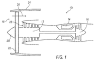
- the gas turbine engine 100 generally may include a compressor section 102, a combustor or combustor section 103, and a turbine section 104. While the gas turbine engine 100 is depicted in FIG. 1 as a multi-shaft configuration, it should be appreciated that the gas turbine engine 100 may be a single-shaft configuration as well. In addition, while the gas turbine engine 100 is depicted as a turbofan, it should further be appreciated that it may be, but is not limited to, a turbofan, a turboshaft, or a turboprop.
- the compressor section 102 may be configured to receive and compress an inlet air stream. The compressed air may then be mixed with a steady stream of fuel and ignited in the combustor 103. The resulting combustion gas may then enter the turbine section 104 in which the combustion gas causes turbine blades to rotate and generate energy.
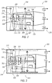
- the combustor 103 generally may include an inner wall 110 and an outer wall 112 defining a combustion chamber 114 there between, and the pressure vessel inner wall 110 generally may be thinner than the structural outer wall 112.
- the difference in thickness may vary depending upon the construction of the combustor 103.
- the outer wall 112 may be a composite outer wall, thereby having a thickness closer to that of the inner wall 112 than if the outer wall 112 is a structural outer wall.
- the relative thickness of the outer wall 112 with respect to the inner wall 110 may determine which approach illustrated in FIG. 2 or FIG. 3 may be implemented, as described in more detail below.
- the inner wall 110 may have a first opening 116, and the outer wall 112 may have a second opening 118 into the combustion chamber 114.
- the gas turbine engine 100 may include a tube 126 through which a cooling fluid, as represented by arrow 121, is routed to the combustion chamber.
- the tube 126 may penetrate at least a portion of the second opening 118, and may be secured to the outer wall 112 via a flange or bracket 128.
- the gas turbine engine 100 may also include a conduit 120 located within the combustion chamber 114 between the first opening 116 and the second opening 118.
- the conduit 120 may enable the cooling fluid 121 to flow from the second opening 118 to the first opening 116.
- the gas turbine engine 100 may further include a first joint 122 and a second joint 124a,b that fluidly connect the conduit 120 to the first opening 116 and the second opening 118, respectively, such that the cooling fluid 121 may flow from the second opening 118 through the conduit 120 to the first opening 116.
- the joints 122 and 124a,b generally may allow for multiple degrees of freedom, including angular and translational, and may include, but are not limited to, floating joints and gimbal joints.
- the first joint 122 and the second joint 124a may both be floating joints, as depicted in FIGS. 4 and 5 and described in more detail below, that enable multiple angular degrees of freedom and a translational degree of freedom of respective ends of the conduit 120.
- This configuration may be implemented when the thickness of the outer wall 112 is much greater than the thickness of the inner wall 110, for example, when the outer wall 112 is a structural outer wall, as explained above.
- the first joint 122 may be a floating joint, as depicted in FIG. 5
- the second joint 124b may be a gimbal joint attached to an end of conduit 120, as depicted in FIG. 6 .
- the floating joint may again enable multiple angular degrees of freedom and a translational degree of freedom of the respective end of the conduit 120, whereas the gimbal joint only enables angular degrees of freedom and no translational degree of freedom of the respective end of the conduit 120.
- This configuration may be implemented when the thickness of the outer wall 112 is closer to that of the inner wall 110, for example when the outer wall 112 is a composite outer wall, as explained above.
- the first joint 122 and the second joint 124a,b are shown in more detail, where FIGS. 4 and 5 depict the second joint 124a and the first joint 122, respectively, as floating joints according to the configuration of FIG. 2 , and FIG. 6 depicts the second joint 124b as a gimbal joint according to the configuration of FIG. 3 .
- the first joint 122 may include a tubular case 130 extending radially from the inner wall 110 into the combustion chamber 114 and around the first opening 116.
- the first joint 122 may also include a spring seal 132 attached to the conduit 120 and configured to engage with the tubular case 130 to prevent any air from exiting the combustion chamber 114 through the first opening 116, as well as to control the translational movement of the conduit 120.
- the second joint 124a,b may also include a tubular case 131a,b extending radially from the outer wall 110 and a spring seal 132 attached to the conduit 120.
- the tubular case 131a of the second joint 124a which may be a floating joint in this configuration, may be attached to the flange 128 and to the tube 126.
- the second joint 124a may also include a retaining ring 134 within the tubular case 131 a and configured to engage with the spring seal 132 after a certain amount of translational movement of the conduit 120 to ensure that the conduit 120 and the second joint 124a do not become disengaged from each other.
- the tubular case 131b of the second joint 124b which may be a gimbal joint as explained above, may be attached to an end of the conduit 120 such that only the other end of the conduit 120 may have translational movement when the inner wall 110 and outer wall 112 experience growth at separate rates.
- the conduit 120 may have different cross-sectional shapes, including but not limited to circular and oval.
- the conduit 120 may be a straight tube or have multiple bends. The shape and configuration of the conduit 120 may be dependent upon different factors, including, but not limited to, available space within the combustor 103.
- the gas turbine engine 100 may include multiple conduits 120 arranged in a radial alignment with the outer wall 112, as illustrated in FIG. 7 , or in a non-radial alignment with the outer wall 112, as illustrated in FIG. 8 . While FIGS. 7 and 8 show four conduits 120 spaced equally around the circumference of the combustor 103, it should be appreciated that the gas turbine engine 100 may include any number of conduits 120 spaced apart from each other at any radial distance.
- the gas turbine engine 100 may also include an outer sleeve 136 disposed around at least a portion of the conduit 120.
- the outer sleeve 136 may be spaced apart from the conduit 120 such that there is an air gap 138 between the outer sleeve 136 and the conduit 120. At least a portion of the air gap 138 may be filled with insulation 140.
- the conduit 120 and/or the outer sleeve 136 may be coated with a thermal barrier 142.
- Method 200 generally may begin at block 202 at which the openings 116 and 118 are provided in the inner wall 110 and the outer wall 112, respectively, of the combustor 103.
- the openings 116 and 118 may be provided such that the conduit 120, installed at block 204, has either a radial alignment with the outer wall 112, as illustrated in FIG. 7 , or a non-radial alignment with the outer wall 112, as illustrated in FIG. 8 .
- method 200 may then proceed to block 204 at which the conduit 120 may be fluidly connected to the first opening 116 and the second opening 118 via the first joint 122 and the second joint 124.
- this may first include attaching or otherwise extending the tubular case 130 into the combustion chamber 114, and attaching the spring seal 132 to an end of the conduit 120.
- the conduit 120 with the spring seal 132 may then be inserted into the first opening 116 until the spring seal 132 and the tubular case 130 engage with each other.
- the spring seal 132 may be attached to an end of the conduit 120, which then may be inserted into the tubular case 131a,b of the second joint 124a,b.
- a retaining ring 134 may then be provided to maintain the end of the conduit 120 within the tubular case 131a.
- the tubular case 131b may be attached to the end of the conduit 120 such that there is no translational degree of freedom of that end of the conduit 120.
- method 200 may end. Method 200 may be repeated as many times as there are conduits 120 installed, for example four conduits 120 as illustrated in FIGS. 7 and 8 .
- method 200 may also include providing an outer sleeve 136 around at least a portion of the conduit 120, providing insulation 140 in at least a portion of an air gap 138 between the outer sleeve 136 and the conduit 120, and/or applying a thermal barrier 142 to at least a portion of the conduit 120 and/or the outer sleeve 136.
Landscapes
- Engineering & Computer Science (AREA)
- Chemical & Material Sciences (AREA)
- Combustion & Propulsion (AREA)
- Mechanical Engineering (AREA)
- General Engineering & Computer Science (AREA)
- Turbine Rotor Nozzle Sealing (AREA)
Abstract
Description
- The present disclosure relates to a gas turbine engine implementing a tubular arrangement in a combustor for turbine cooled cooling air.
- A gas turbine engine generally includes a compressor section, a combustor or combustor section, and a turbine section. The compressor section receives and compresses a flow of intake air. The compressed air then enters the combustor section in which a steady stream of fuel is injected, mixed with the compressed air, and ignited, resulting in high energy combustion gas, which is then directed to the turbine section. Some gas turbine engines may also include a source for providing a cooling fluid, such as air, within the engine, for example upstream of the turbine section and/or downstream of the compressor section. The cooling fluid may be circulated through the engine and a heat exchanger via a tube or conduit, which may be routed through the combustor.
- The combustor generally includes an inner wall and an outer wall defining a combustion chamber there between, where the inner wall and the outer wall have different thicknesses for structural and pressure containment purposes. The compressed air discharged from the compressor section typically is at high temperatures, and therefore heats the combustor walls as it is introduced into the combustor. However, because of the different thicknesses, the inner wall and the outer wall may thermally grow at different rates. This, in turn, may affect or limit the implementation of any structures that interface with the walls, such as a tube or conduit within the combustion chamber that are through which the cooling fluid flows.
- As such, there exists a need for a gas turbine engine that accounts for the differential thermal growth between the inner wall and the outer wall of the combustor. In particular, there exists a need for a gas turbine engine implementing a tubular arrangement for providing turbine cooling air such that the tubular arrangement may be provided in the combustion chamber and accommodates the differential thermal growth between the inner wall and the outer wall of the combustor.
- According to the present disclosure, there is provided a gas turbine engine including a conduit for circulating a cooling fluid and a method for implementing a conduit in a gas turbine engine, as set forth in the appended claims.
- While the claims are not limited to a specific illustration, an appreciation of the various aspects is best gained through a discussion of various examples thereof. Referring now to the drawings, exemplary illustrations are shown in detail. Although the drawings represent the illustrations, the drawings are not necessarily to scale and certain features may be exaggerated to better illustrate and explain an innovative aspect of an example. Further, the exemplary illustrations described herein are not intended to be exhaustive or otherwise limiting or restricted to the precise form and configuration shown in the drawings and disclosed in the following detailed description. Exemplary illustrations are described in detail by referring to the drawings as follows:
-
FIG. 1 illustrates a schematic view of an exemplary gas turbine engine employing the improvements discussed herein; -
FIGS. 2 and 3 illustrate schematic partial, cross-sectional views of a combustor of the gas turbine engine ofFIG. 1 with a mobile conduit installed therein according to different exemplary approaches; -
FIG. 4 illustrate an enlarged view of an upper floating joint at an outer wall of the combustor as implemented in the exemplary approach illustrated inFIG. 2 ; -
FIG. 5 illustrates an enlarged view of a lower floating joint at an inner wall of the combustor as implemented in the exemplary approaches illustrated inFIGS. 2 and 3 ; -
FIG. 6 illustrates an enlarged view of an upper gimbal joint at an outer wall of the combustor as implemented in the exemplary approach illustrated inFIG. 3 ; -
FIGS. 7 and8 illustrate schematic diagrams of an alignment of multiple conduits according to different exemplary approaches; - FIG. 9 illustrates a schematic view of the mobile conduit with a double wall to accommodate an insulation feature of
FIGS. 2 and 3 ; and - FIG. 10 illustrates an exemplary method for implementing the exemplary approaches illustrated in
FIGS. 2 and 3 . - A gas turbine engine generally may circulate a cooling fluid, such as air, from the engine to a heat exchanger. An exemplary gas turbine engine may include at least one mobile conduit through which the cooling fluid may flow and that may be positioned in a combustor of the gas turbine engine. The combustor generally may include an inner wall and an outer wall defining a combustion chamber there between, and the inner wall and the outer wall may each have at least one opening into the combustion chamber. The gas turbine engine may have a first joint and a second joint that fluidly connect the at least one mobile conduit to the at least one opening in the inner wall and the at least one opening in the outer wall, respectively, such that the cooling fluid may flow from the opening in the outer wall to the opening in the inner wall through the at least one mobile conduit. The first joint and the second joint may enable multiple degrees of freedom of the at least one mobile conduit within the combustion chamber, for example, to account for different rates of expansion of the inner wall and the outer wall. The first joint and/or the second joint may be floating joints that allow for multiple angular degrees of freedom and a translational degree of freedom of respective ends of the at least one mobile conduit. Alternatively, the second joint may be a gimbal joint that allows for multiple angular degrees of freedom with no translational degree of freedom of a respective end of the at least one mobile conduit.
- An exemplary method for implementing a conduit in the gas turbine engine as described above may include first providing a first opening in the inner wall of the combustor, and providing a second opening in the outer wall of the combustor. The method may then include fluidly connecting the conduit to the first opening via a first joint and to the second opening via the second joint such that the cooling fluid may flow through the conduit from the second opening to the first opening. As explained above, the first joint and the second joint may enable multiple degrees of freedom of the conduit within the combustion chamber.
- Referring to the figures, an exemplary gas turbine engine 100 is shown in
FIG. 1 . The gas turbine engine 100 generally may include a compressor section 102, a combustor or combustor section 103, and a turbine section 104. While the gas turbine engine 100 is depicted inFIG. 1 as a multi-shaft configuration, it should be appreciated that the gas turbine engine 100 may be a single-shaft configuration as well. In addition, while the gas turbine engine 100 is depicted as a turbofan, it should further be appreciated that it may be, but is not limited to, a turbofan, a turboshaft, or a turboprop. The compressor section 102 may be configured to receive and compress an inlet air stream. The compressed air may then be mixed with a steady stream of fuel and ignited in the combustor 103. The resulting combustion gas may then enter the turbine section 104 in which the combustion gas causes turbine blades to rotate and generate energy. - Referring to
FIGS. 2 and 3 , a partial section of the combustor 103 is shown. The combustor 103 generally may include an inner wall 110 and an outer wall 112 defining a combustion chamber 114 there between, and the pressure vessel inner wall 110 generally may be thinner than the structural outer wall 112. The difference in thickness may vary depending upon the construction of the combustor 103. For example, the outer wall 112 may be a composite outer wall, thereby having a thickness closer to that of the inner wall 112 than if the outer wall 112 is a structural outer wall. The relative thickness of the outer wall 112 with respect to the inner wall 110 may determine which approach illustrated inFIG. 2 or FIG. 3 may be implemented, as described in more detail below. The inner wall 110 may have a first opening 116, and the outer wall 112 may have a second opening 118 into the combustion chamber 114. The gas turbine engine 100 may include a tube 126 through which a cooling fluid, as represented by arrow 121, is routed to the combustion chamber. The tube 126 may penetrate at least a portion of the second opening 118, and may be secured to the outer wall 112 via a flange or bracket 128. - The gas turbine engine 100 may also include a conduit 120 located within the combustion chamber 114 between the first opening 116 and the second opening 118. The conduit 120 may enable the cooling fluid 121 to flow from the second opening 118 to the first opening 116. The gas turbine engine 100 may further include a first joint 122 and a second joint 124a,b that fluidly connect the conduit 120 to the first opening 116 and the second opening 118, respectively, such that the cooling fluid 121 may flow from the second opening 118 through the conduit 120 to the first opening 116. The joints 122 and 124a,b generally may allow for multiple degrees of freedom, including angular and translational, and may include, but are not limited to, floating joints and gimbal joints.
- In one exemplary approach depicted in
FIG. 2 , the first joint 122 and the second joint 124a may both be floating joints, as depicted inFIGS. 4 and 5 and described in more detail below, that enable multiple angular degrees of freedom and a translational degree of freedom of respective ends of the conduit 120. This configuration may be implemented when the thickness of the outer wall 112 is much greater than the thickness of the inner wall 110, for example, when the outer wall 112 is a structural outer wall, as explained above. - In another exemplary approach depicted in
FIG. 3 , the first joint 122 may be a floating joint, as depicted inFIG. 5 , and the second joint 124b may be a gimbal joint attached to an end of conduit 120, as depicted inFIG. 6 . The floating joint may again enable multiple angular degrees of freedom and a translational degree of freedom of the respective end of the conduit 120, whereas the gimbal joint only enables angular degrees of freedom and no translational degree of freedom of the respective end of the conduit 120. This configuration may be implemented when the thickness of the outer wall 112 is closer to that of the inner wall 110, for example when the outer wall 112 is a composite outer wall, as explained above. - Referring to
FIGS. 4-6 , the first joint 122 and the second joint 124a,b are shown in more detail, whereFIGS. 4 and 5 depict the second joint 124a and the first joint 122, respectively, as floating joints according to the configuration ofFIG. 2 , andFIG. 6 depicts the second joint 124b as a gimbal joint according to the configuration ofFIG. 3 . In each configuration, the first joint 122 may include a tubular case 130 extending radially from the inner wall 110 into the combustion chamber 114 and around the first opening 116. The first joint 122 may also include a spring seal 132 attached to the conduit 120 and configured to engage with the tubular case 130 to prevent any air from exiting the combustion chamber 114 through the first opening 116, as well as to control the translational movement of the conduit 120. - The second joint 124a,b may also include a tubular case 131a,b extending radially from the outer wall 110 and a spring seal 132 attached to the conduit 120. In the configuration depicted in
FIGS. 2 and4 , the tubular case 131a of the second joint 124a, which may be a floating joint in this configuration, may be attached to the flange 128 and to the tube 126. The second joint 124a may also include a retaining ring 134 within the tubular case 131 a and configured to engage with the spring seal 132 after a certain amount of translational movement of the conduit 120 to ensure that the conduit 120 and the second joint 124a do not become disengaged from each other. In the embodiment depicted inFIGS. 3 and6 , the tubular case 131b of the second joint 124b, which may be a gimbal joint as explained above, may be attached to an end of the conduit 120 such that only the other end of the conduit 120 may have translational movement when the inner wall 110 and outer wall 112 experience growth at separate rates. - Referring back to
FIGS. 2 and 3 , the conduit 120 may have different cross-sectional shapes, including but not limited to circular and oval. In addition, the conduit 120 may be a straight tube or have multiple bends. The shape and configuration of the conduit 120 may be dependent upon different factors, including, but not limited to, available space within the combustor 103. Furthermore, the gas turbine engine 100 may include multiple conduits 120 arranged in a radial alignment with the outer wall 112, as illustrated inFIG. 7 , or in a non-radial alignment with the outer wall 112, as illustrated inFIG. 8 . WhileFIGS. 7 and8 show four conduits 120 spaced equally around the circumference of the combustor 103, it should be appreciated that the gas turbine engine 100 may include any number of conduits 120 spaced apart from each other at any radial distance. - Referring now to FIG. 9, the gas turbine engine 100 may also include an outer sleeve 136 disposed around at least a portion of the conduit 120. The outer sleeve 136 may be spaced apart from the conduit 120 such that there is an air gap 138 between the outer sleeve 136 and the conduit 120. At least a portion of the air gap 138 may be filled with insulation 140. Alternatively or additionally, the conduit 120 and/or the outer sleeve 136 may be coated with a thermal barrier 142.
- Referring now to FIG. 10, an
exemplary method 200 for implementing the approaches illustrated inFIGS. 2 and 3 is shown.Method 200 generally may begin atblock 202 at which the openings 116 and 118 are provided in the inner wall 110 and the outer wall 112, respectively, of the combustor 103. The openings 116 and 118 may be provided such that the conduit 120, installed atblock 204, has either a radial alignment with the outer wall 112, as illustrated inFIG. 7 , or a non-radial alignment with the outer wall 112, as illustrated inFIG. 8 . Afterblock 202,method 200 may then proceed to block 204 at which the conduit 120 may be fluidly connected to the first opening 116 and the second opening 118 via the first joint 122 and the second joint 124. With respect to the first joint 122, this may first include attaching or otherwise extending the tubular case 130 into the combustion chamber 114, and attaching the spring seal 132 to an end of the conduit 120. The conduit 120 with the spring seal 132 may then be inserted into the first opening 116 until the spring seal 132 and the tubular case 130 engage with each other. With respect to the second joint 124a,b, the spring seal 132 may be attached to an end of the conduit 120, which then may be inserted into the tubular case 131a,b of the second joint 124a,b. When the joint 124a is a floating joint, a retaining ring 134 may then be provided to maintain the end of the conduit 120 within the tubular case 131a. When the joint 124b is a gimbal joint, the tubular case 131b may be attached to the end of the conduit 120 such that there is no translational degree of freedom of that end of the conduit 120. - After
block 204,method 200 may end.Method 200 may be repeated as many times as there are conduits 120 installed, for example four conduits 120 as illustrated inFIGS. 7 and8 . - In addition,
method 200 may also include providing an outer sleeve 136 around at least a portion of the conduit 120, providing insulation 140 in at least a portion of an air gap 138 between the outer sleeve 136 and the conduit 120, and/or applying a thermal barrier 142 to at least a portion of the conduit 120 and/or the outer sleeve 136. - Aspects of the disclosure will be described below by numbered clauses:
- 1. A gas turbine engine 100 comprising:
- a combustor 103 having an inner wall 110 and an outer wall 112 defining a combustion chamber 114 there between, the inner wall 110 and the outer wall 112 each having at least one opening 116, 118 into the combustion chamber 114;
- at least one
mobile conduit 12 through which a cooling fluid 121 is flowable, the at least one mobile conduit 120 passing through the combustion chamber 114 from the at least one opening 118 in the outer wall 112 to the at least one opening 116 in the inner wall 110; and - a first joint 122 and a second joint 124a, 124b fluidly connecting the at least one mobile conduit 120 with the at least one opening 116 in the inner wall 110 and the at least one opening 118 in the outer wall 112, respectively the first joint 122 and the second joint 124a, 124b enabling multiple degrees of freedom of the at least one mobile conduit 120 within the combustion chamber 114.
- 2. The gas turbine engine 100 of clause 1, wherein the first joint 122 and the second joint 124a are floating joints enabling the at least one mobile conduit 120 to slide with respect to both the openings 116, 118 in the inner wall 110 and the outer wall 112.
- 3. The gas turbine engine 100 of clause 1, wherein the first joint 122 is a floating joint, and the second joint 124b is a gimbal joint attached to an end of the at least one mobile conduit 120 at the outer wall 112 such that an end of the mobile conduit 120 at the inner wall 110 is able to slide with respect to the at least one opening 116 in the inner wall 110.
- 4. The gas turbine engine 100 of clause 1 or 2, wherein the first joint 122 and the second joint 124a, 124b each includes a tubular case 130, 131a, 131b extending from the inner wall 110 and the outer wall 112, respectively, into the combustion chamber 114 around the respective openings 116, 118, and at least one spring loaded seal 132, and wherein one of the first joint 122 and the second joint 124a, 124b further includes a retaining ring 134 within the tubular case 130, 131a, 131b to limit a translational degree of freedom of the mobile conduit 120.
- 5. The gas turbine engine 100 of clause 3, wherein the first joint 122 and the second joint 124a, 124b each includes a tubular case 130, 131a, 131b extending from the inner wall 110 and the outer wall 112, respectively, into the combustion chamber 114 around the respective openings 116, 118, and at least one spring loaded seal 132.
- 6. The gas turbine engine 100 of any one of the preceding clauses, wherein the at least one mobile conduit 120 includes four conduits arranged in one of a radial alignment with the outer wall 112 and a non-radial alignment with the outer wall 112.
- 7. The gas turbine engine 100 of any one of the preceding clauses, further comprising an outer sleeve 136 disposed around at least a portion of the at least one mobile conduit 120.
- 8. The gas turbine engine 100 of clause 7, wherein the outer sleeve 136 is spaced apart from the at least one mobile conduit 120 such that an air tight cavity 138 is created there between.
- 9. The gas turbine engine 100 of clause 8, wherein at least a portion of the air tight cavity 138 is filled with insulation 140.
- 10. The gas turbine engine 100 of one of clauses 7 to 9, further comprising a thermal barrier coating 142 on at least a portion of at least one of the at least one mobile conduit 120 and the outer sleeve 136.
- 11. The gas turbine engine 100 of any one of clauses 1 to 6, further comprising a thermal barrier coating 140 on at least a portion of the at least one mobile conduit 120.
- 12. A
method 200 comprising:- providing 202 a first opening 116 in an inner wall 110 of a combustor 103 of a gas turbine engine 100, and a second opening 118 in an outer wall 112 of the combustor 103, the outer wall 112 and the inner wall 110 defining a combustion chamber 114 there between;
- fluidly connecting 204 a conduit 120 in the combustion chamber 114 to the first opening 116 in the inner wall 110 via a first joint 112 and to the second opening 118 in the outer wall 112 via a second joint 124a, 124b such that a cooling fluid 121 is flowable through the conduit 120 from the second opening 118 to the first opening 116;
- wherein the first joint 122 and the second joint 124a, 124b enable multiple degrees of freedom of the conduit 120 within the combustion chamber 114; and
- wherein the first joint 122 is a floating joint, and the second joint 124a, 124b is one of a floating joint 124a and a gimbal joint 124b.
- 13. The
method 200 ofclause 12, wherein the first joint 122 and the second joint 124a are floating joints enabling the conduit 120 to slide with respect to both the openings 116, 118 in the inner wall 110 and the outer wall 112. - 14. The
method 200 ofclause 12, wherein the first joint 122 is a floating joint, and the second joint 124b is a gimbal joint attached to an end of the conduit 120 near the outer wall 112 such that an end of the conduit 120 near the inner wall 110 is able to slide with respect to the opening 116 in the inner wall 110. - 15. The
method 200 of one ofclauses 12 to 14, further comprising aligning the conduit 120 with the outer wall 112 in one of a radial alignment with the outer wall 112 and a non-radial alignment with the outer wall 112. - 16. A gas turbine engine 100 comprising:
- a combustor 103 having an inner wall 110 and an outer wall 112 defining a combustion chamber 114 there between, the inner wall 110 and the outer wall 112 each having at least one opening 116, 118 into the combustion chamber 114;
- at least one mobile conduit 120 through which a cooling fluid 121 is flowable, the at least one mobile conduit 120 passing through the combustion chamber 114 from the at least one opening 118 in the outer wall 112 to the at least one opening 116 in the inner wall 110;
- a first joint 122 fluidly connecting the at least one mobile conduit 120 to the first opening 116; and
- a second joint 124a, 124b fluidly connecting the at least one mobile conduit 120 to the second opening 118;
- wherein the first joint 122 is a floating joint, and the second joint 124a, 124b is one of a floating joint 124a and a gimbal joint 124b attached to an end of the at least one mobile conduit 120 near the outer wall 112, the floating joints 122, 124a enabling multiple angular degrees of freedom and a translational degree of freedom of a respective end of the at least one mobile conduit 120, and the gimbal joint 124b enabling multiple angular degrees of freedom with no translational degree of freedom of a respective end of the at least one mobile conduit 120.
- 17. The gas turbine engine 100 of
clause 16, wherein the second joint 124a, 124b is a floating joint 124a such that the respective ends of the at least one mobile conduit 120 are able to slide with respect to the openings 116, 118 in the outer wall 112 and the inner wall 110. - 18. The gas turbine engine 100 of
clause 16 or 17, wherein the second joint 124a, 124b is the gimbal joint 124b attached to an end of the at least one mobile conduit 120 near the outer wall 112 such that only an end of the at least one mobile conduit 120 near the inner wall 110 is able to slide with respect to the opening 116 in the inner wall 110. - 19. The gas turbine engine 100 of any one of
clauses 16 to 18, wherein the first joint 122 and the second joint 124a, 124b each includes a tubular case 130, 131a, 131b extending from the inner wall 110 and the outer wall 112, respectively, into the combustion chamber 114 around the respective openings 116, 118, and at least one spring loaded seal 132, and wherein one of the first joint 122 and the second joint 124a, 124b further includes a retaining ring 134 within the tubular case 130, 131a, 131b to limit the translational degree of freedom of the mobile conduit 120. - 20. The gas turbine engine 100 of any one of
clauses 16 to 19, further comprising an outer sleeve 136 disposed around at least a portion of the at least one mobile conduit 120 such that there is an air tight cavity 138 between the conduit 120 and the outer sleeve 136. - With regard to the processes, systems, methods, heuristics, etc. described herein, it should be understood that, although the steps of such processes, etc. have been described as occurring according to a certain ordered sequence, such processes could be practiced with the described steps performed in an order other than the order described herein. It further should be understood that certain steps could be performed simultaneously, that other steps could be added, or that certain steps described herein could be omitted. In other words, the descriptions of processes herein are provided for the purpose of illustrating certain embodiments, and should in no way be construed so as to limit the claims
- It will be appreciated that the aforementioned method and devices may be modified to have some components and steps removed, or may have additional components and steps added, all of which are deemed to be within the spirit of the present disclosure. Even though the present disclosure has been described in detail with reference to specific embodiments, it will be appreciated that the various modifications and changes can be made to these embodiments without departing from the scope of the present disclosure as set forth in the claims. The specification and the drawings are to be regarded as an illustrative thought instead of merely restrictive thought.
Claims (15)
- A gas turbine engine (100) comprising:a combustor (103) having an inner wall (110) and an outer wall (112) defining a combustion chamber (114) there between, the inner wall (110) and the outer wall (112) each having at least one opening (116, 118) into the combustion chamber (114);at least one mobile conduit (12) through which a cooling fluid (121) is flowable, the at least one mobile conduit (120) passing through the combustion chamber (114) from the at least one opening (118) in the outer wall (112) to the at least one opening (116) in the inner wall (110); anda first joint (122) and a second joint (124a, 124b) fluidly connecting the at least one mobile conduit (120) with the at least one opening (116) in the inner wall (110) and the at least one opening (118) in the outer wall (112), respectively the first joint (122) and the second joint (124a, 124b) enabling multiple degrees of freedom of the at least one mobile conduit (120) within the combustion chamber (114).
- The gas turbine engine (100) of claim 1, wherein the first joint (122) and the second joint (124a) are floating joints enabling the at least one mobile conduit (120) to slide with respect to both the openings (116, 118) in the inner wall (110) and the outer wall (112).
- The gas turbine engine (100) of claim 1, wherein the first joint (122) is a floating joint, and the second joint (124b) is a gimbal joint attached to an end of the at least one mobile conduit (120) at the outer wall (112) such that an end of the mobile conduit (120) at the inner wall (110) is able to slide with respect to the at least one opening (116) in the inner wall (110).
- The gas turbine engine (100) of claim 1 or 2, wherein the first joint (122) and the second joint (124a, 124b) each includes a tubular case (130, 131a, 131b) extending from the inner wall (110) and the outer wall (112), respectively, into the combustion chamber (114) around the respective openings (116, 118), and at least one spring loaded seal (132), and wherein one of the first joint (122) and the second joint (124a, 124b) further includes a retaining ring (134) within the tubular case (130, 131a, 131b) to limit a translational degree of freedom of the mobile conduit (120).
- The gas turbine engine (100) of claim 3, wherein the first joint (122) and the second joint (124a, 124b) each includes a tubular case (130, 131a, 131b) extending from the inner wall (110) and the outer wall (112), respectively, into the combustion chamber (114) around the respective openings (116, 118), and at least one spring loaded seal (132).
- The gas turbine engine (100) of any one of the preceding claims, wherein the at least one mobile conduit (120) includes four conduits arranged in one of a radial alignment with the outer wall (112) and a non-radial alignment with the outer wall (112).
- The gas turbine engine (100) of any one of the preceding claims, further comprising an outer sleeve (136) disposed around at least a portion of the at least one mobile conduit (120).
- The gas turbine engine (100) of claim 7, wherein the outer sleeve (136) is spaced apart from the at least one mobile conduit (120) such that an air tight cavity (138) is created there between.
- The gas turbine engine (100) of claim 8, wherein at least a portion of the air tight cavity (138) is filled with insulation (140).
- The gas turbine engine (100) of one of claims 7 to 9, further comprising a thermal barrier coating (142) on at least a portion of at least one of the at least one mobile conduit (120) and the outer sleeve (136).
- The gas turbine engine (100) of any one of claims 1 to 6, further comprising a thermal barrier coating (140) on at least a portion of the at least one mobile conduit (120).
- A method (200) comprising:providing (202) a first opening (116) in an inner wall (110) of a combustor (103) of a gas turbine engine (100), and a second opening (118) in an outer wall (112) of the combustor (103), the outer wall (112) and the inner wall (110) defining a combustion chamber (114) there between;fluidly connecting (204) a conduit (120) in the combustion chamber (114) to the first opening (116) in the inner wall (110) via a first joint (112) and to the second opening (118) in the outer wall (112) via a second joint (124a, 124b) such that a cooling fluid (121) is flowable through the conduit (120) from the second opening (118) to the first opening (116);wherein the first joint (122) and the second joint (124a, 124b) enable multiple degrees of freedom of the conduit (120) within the combustion chamber (114); andwherein the first joint (122) is a floating joint, and the second joint (124a, 124b) is one of a floating joint (124a) and a gimbal joint (124b).
- The method (200) of claim 12, wherein the first joint (122) and the second joint (124a) are floating joints enabling the conduit (120) to slide with respect to both the openings (116, 118) in the inner wall (110) and the outer wall (112).
- The method (200) of claim 12, wherein the first joint (122) is a floating joint, and the second joint (124b) is a gimbal joint attached to an end of the conduit (120) near the outer wall (112) such that an end of the conduit (120) near the inner wall (110) is able to slide with respect to the opening (116) in the inner wall (110).
- The method (200) of one of claims 12 to 14, further comprising aligning the conduit (120) with the outer wall (112) in one of a radial alignment with the outer wall (112) and a non-radial alignment with the outer wall (112).
Applications Claiming Priority (1)
| Application Number | Priority Date | Filing Date | Title |
|---|---|---|---|
| US201562181836P | 2015-06-19 | 2015-06-19 |
Publications (2)
| Publication Number | Publication Date |
|---|---|
| EP3109550A1 true EP3109550A1 (en) | 2016-12-28 |
| EP3109550B1 EP3109550B1 (en) | 2019-09-04 |
Family
ID=56296489
Family Applications (1)
| Application Number | Title | Priority Date | Filing Date |
|---|---|---|---|
| EP16174173.1A Active EP3109550B1 (en) | 2015-06-19 | 2016-06-13 | Turbine cooled cooling air flowing through a tubular arrangement |
Country Status (3)
| Country | Link |
|---|---|
| US (1) | US10767864B2 (en) |
| EP (1) | EP3109550B1 (en) |
| CA (1) | CA2933344A1 (en) |
Families Citing this family (2)
| Publication number | Priority date | Publication date | Assignee | Title |
|---|---|---|---|---|
| US10208668B2 (en) | 2015-09-30 | 2019-02-19 | Rolls-Royce Corporation | Turbine engine advanced cooling system |
| EP3550106B1 (en) | 2018-04-06 | 2024-10-09 | RTX Corporation | Cooling air for gas turbine engine with thermally isolated cooling air delivery |
Citations (5)
| Publication number | Priority date | Publication date | Assignee | Title |
|---|---|---|---|---|
| GB588847A (en) * | 1944-11-28 | 1947-06-04 | William Henry Darlington | Improvements in combustion chambers for internal combustion turbines |
| US4454711A (en) * | 1981-10-29 | 1984-06-19 | Avco Corporation | Self-aligning fuel nozzle assembly |
| EP1074792A1 (en) * | 1999-07-31 | 2001-02-07 | Rolls-Royce Plc | Turbine combustor arrangement |
| US20050016182A1 (en) * | 2003-07-08 | 2005-01-27 | Oleg Morenko | Combustor attachment with rotational joint |
| EP2546574A2 (en) * | 2011-07-13 | 2013-01-16 | United Technologies Corporation | Ceramic matrix composite combustor vane ring assembly |
Family Cites Families (12)
| Publication number | Priority date | Publication date | Assignee | Title |
|---|---|---|---|---|
| US7449165B2 (en) | 2004-02-03 | 2008-11-11 | Ut-Battelle, Llc | Robust carbon monolith having hierarchical porosity |
| US7631502B2 (en) | 2005-12-14 | 2009-12-15 | United Technologies Corporation | Local cooling hole pattern |
| US7823389B2 (en) | 2006-11-15 | 2010-11-02 | General Electric Company | Compound clearance control engine |
| US8616004B2 (en) | 2007-11-29 | 2013-12-31 | Honeywell International Inc. | Quench jet arrangement for annular rich-quench-lean gas turbine combustors |
| US8161752B2 (en) * | 2008-11-20 | 2012-04-24 | Honeywell International Inc. | Combustors with inserts between dual wall liners |
| US9897320B2 (en) | 2009-07-30 | 2018-02-20 | Honeywell International Inc. | Effusion cooled dual wall gas turbine combustors |
| US8307662B2 (en) | 2009-10-15 | 2012-11-13 | General Electric Company | Gas turbine engine temperature modulated cooling flow |
| US20110185739A1 (en) | 2010-01-29 | 2011-08-04 | Honeywell International Inc. | Gas turbine combustors with dual walled liners |
| US8359866B2 (en) | 2010-02-04 | 2013-01-29 | United Technologies Corporation | Combustor liner segment seal member |
| US20140216042A1 (en) | 2012-09-28 | 2014-08-07 | United Technologies Corporation | Combustor component with cooling holes formed by additive manufacturing |
| EP2738469B1 (en) | 2012-11-30 | 2019-04-17 | Ansaldo Energia IP UK Limited | Combustor part of a gas turbine comprising a near wall cooling arrangement |
| US9765968B2 (en) | 2013-01-23 | 2017-09-19 | Honeywell International Inc. | Combustors with complex shaped effusion holes |
-
2016
- 2016-06-13 EP EP16174173.1A patent/EP3109550B1/en active Active
- 2016-06-16 CA CA2933344A patent/CA2933344A1/en not_active Abandoned
- 2016-06-17 US US15/185,431 patent/US10767864B2/en active Active
Patent Citations (5)
| Publication number | Priority date | Publication date | Assignee | Title |
|---|---|---|---|---|
| GB588847A (en) * | 1944-11-28 | 1947-06-04 | William Henry Darlington | Improvements in combustion chambers for internal combustion turbines |
| US4454711A (en) * | 1981-10-29 | 1984-06-19 | Avco Corporation | Self-aligning fuel nozzle assembly |
| EP1074792A1 (en) * | 1999-07-31 | 2001-02-07 | Rolls-Royce Plc | Turbine combustor arrangement |
| US20050016182A1 (en) * | 2003-07-08 | 2005-01-27 | Oleg Morenko | Combustor attachment with rotational joint |
| EP2546574A2 (en) * | 2011-07-13 | 2013-01-16 | United Technologies Corporation | Ceramic matrix composite combustor vane ring assembly |
Also Published As
| Publication number | Publication date |
|---|---|
| US20160370010A1 (en) | 2016-12-22 |
| EP3109550B1 (en) | 2019-09-04 |
| CA2933344A1 (en) | 2016-12-19 |
| US10767864B2 (en) | 2020-09-08 |
Similar Documents
| Publication | Publication Date | Title |
|---|---|---|
| US8943827B2 (en) | Fuel air heat exchanger | |
| US10550767B2 (en) | Gas turbine engine recuperator with floating connection | |
| EP2927426B1 (en) | Cooling system with a bearing compartment bypass and corresponding method | |
| CA2597592C (en) | Gas turbine combustor and fuel manifold mounting arrangement | |
| EP2492472B1 (en) | Diffusing Gas Turbine Engine Recuperator | |
| US9109842B2 (en) | Fuel air heat exchanger | |
| US20170107906A1 (en) | De-icing device for a splitter nose of an axial turbine engine compressor | |
| US9932903B2 (en) | Fuel manifold and fuel injector arrangement | |
| US8651809B2 (en) | Apparatus and method for aligning a turbine casing | |
| CA2890776C (en) | Bypass-cooled internal fuel manifold and method | |
| US10132193B2 (en) | Gas turbine engine duct assembly | |
| EP2963346A1 (en) | Self-cooled orifice structure | |
| CN106415131B (en) | annular turbomachinery combustor | |
| EP3056680B1 (en) | Leakage air systems for turbomachines | |
| EP2896808B1 (en) | Internal manifold with fuel inlet | |
| US10408456B2 (en) | Combustion chamber assembly | |
| US10519873B2 (en) | Air bypass system for rotor shaft cooling | |
| CN107869392A (en) | Mounting assembly for gas-turbine unit fluid circuit | |
| EP3109550B1 (en) | Turbine cooled cooling air flowing through a tubular arrangement | |
| US20120097756A1 (en) | System and method for cooling a nozzle | |
| CN107228381A (en) | Transition duct component with slow injection structure |
Legal Events
| Date | Code | Title | Description |
|---|---|---|---|
| PUAI | Public reference made under article 153(3) epc to a published international application that has entered the european phase |
Free format text: ORIGINAL CODE: 0009012 |
|
| STAA | Information on the status of an ep patent application or granted ep patent |
Free format text: STATUS: THE APPLICATION HAS BEEN PUBLISHED |
|
| AK | Designated contracting states |
Kind code of ref document: A1 Designated state(s): AL AT BE BG CH CY CZ DE DK EE ES FI FR GB GR HR HU IE IS IT LI LT LU LV MC MK MT NL NO PL PT RO RS SE SI SK SM TR |
|
| AX | Request for extension of the european patent |
Extension state: BA ME |
|
| STAA | Information on the status of an ep patent application or granted ep patent |
Free format text: STATUS: REQUEST FOR EXAMINATION WAS MADE |
|
| 17P | Request for examination filed |
Effective date: 20170628 |
|
| RBV | Designated contracting states (corrected) |
Designated state(s): AL AT BE BG CH CY CZ DE DK EE ES FI FR GB GR HR HU IE IS IT LI LT LU LV MC MK MT NL NO PL PT RO RS SE SI SK SM TR |
|
| STAA | Information on the status of an ep patent application or granted ep patent |
Free format text: STATUS: EXAMINATION IS IN PROGRESS |
|
| 17Q | First examination report despatched |
Effective date: 20180611 |
|
| GRAP | Despatch of communication of intention to grant a patent |
Free format text: ORIGINAL CODE: EPIDOSNIGR1 |
|
| STAA | Information on the status of an ep patent application or granted ep patent |
Free format text: STATUS: GRANT OF PATENT IS INTENDED |
|
| INTG | Intention to grant announced |
Effective date: 20190409 |
|
| GRAS | Grant fee paid |
Free format text: ORIGINAL CODE: EPIDOSNIGR3 |
|
| GRAA | (expected) grant |
Free format text: ORIGINAL CODE: 0009210 |
|
| STAA | Information on the status of an ep patent application or granted ep patent |
Free format text: STATUS: THE PATENT HAS BEEN GRANTED |
|
| AK | Designated contracting states |
Kind code of ref document: B1 Designated state(s): AL AT BE BG CH CY CZ DE DK EE ES FI FR GB GR HR HU IE IS IT LI LT LU LV MC MK MT NL NO PL PT RO RS SE SI SK SM TR |
|
| REG | Reference to a national code |
Ref country code: GB Ref legal event code: FG4D |
|
| REG | Reference to a national code |
Ref country code: CH Ref legal event code: EP |
|
| REG | Reference to a national code |
Ref country code: AT Ref legal event code: REF Ref document number: 1175875 Country of ref document: AT Kind code of ref document: T Effective date: 20190915 |
|
| REG | Reference to a national code |
Ref country code: DE Ref legal event code: R096 Ref document number: 602016019747 Country of ref document: DE |
|
| REG | Reference to a national code |
Ref country code: IE Ref legal event code: FG4D |
|
| REG | Reference to a national code |
Ref country code: NL Ref legal event code: MP Effective date: 20190904 |
|
| REG | Reference to a national code |
Ref country code: LT Ref legal event code: MG4D |
|
| PG25 | Lapsed in a contracting state [announced via postgrant information from national office to epo] |
Ref country code: NO Free format text: LAPSE BECAUSE OF FAILURE TO SUBMIT A TRANSLATION OF THE DESCRIPTION OR TO PAY THE FEE WITHIN THE PRESCRIBED TIME-LIMIT Effective date: 20191204 Ref country code: BG Free format text: LAPSE BECAUSE OF FAILURE TO SUBMIT A TRANSLATION OF THE DESCRIPTION OR TO PAY THE FEE WITHIN THE PRESCRIBED TIME-LIMIT Effective date: 20191204 Ref country code: SE Free format text: LAPSE BECAUSE OF FAILURE TO SUBMIT A TRANSLATION OF THE DESCRIPTION OR TO PAY THE FEE WITHIN THE PRESCRIBED TIME-LIMIT Effective date: 20190904 Ref country code: HR Free format text: LAPSE BECAUSE OF FAILURE TO SUBMIT A TRANSLATION OF THE DESCRIPTION OR TO PAY THE FEE WITHIN THE PRESCRIBED TIME-LIMIT Effective date: 20190904 Ref country code: FI Free format text: LAPSE BECAUSE OF FAILURE TO SUBMIT A TRANSLATION OF THE DESCRIPTION OR TO PAY THE FEE WITHIN THE PRESCRIBED TIME-LIMIT Effective date: 20190904 Ref country code: LT Free format text: LAPSE BECAUSE OF FAILURE TO SUBMIT A TRANSLATION OF THE DESCRIPTION OR TO PAY THE FEE WITHIN THE PRESCRIBED TIME-LIMIT Effective date: 20190904 |
|
| RAP2 | Party data changed (patent owner data changed or rights of a patent transferred) |
Owner name: ROLLS-ROYCE CORPORATION Owner name: ROLLS-ROYCE PLC |
|
| PG25 | Lapsed in a contracting state [announced via postgrant information from national office to epo] |
Ref country code: AL Free format text: LAPSE BECAUSE OF FAILURE TO SUBMIT A TRANSLATION OF THE DESCRIPTION OR TO PAY THE FEE WITHIN THE PRESCRIBED TIME-LIMIT Effective date: 20190904 Ref country code: LV Free format text: LAPSE BECAUSE OF FAILURE TO SUBMIT A TRANSLATION OF THE DESCRIPTION OR TO PAY THE FEE WITHIN THE PRESCRIBED TIME-LIMIT Effective date: 20190904 Ref country code: ES Free format text: LAPSE BECAUSE OF FAILURE TO SUBMIT A TRANSLATION OF THE DESCRIPTION OR TO PAY THE FEE WITHIN THE PRESCRIBED TIME-LIMIT Effective date: 20190904 Ref country code: GR Free format text: LAPSE BECAUSE OF FAILURE TO SUBMIT A TRANSLATION OF THE DESCRIPTION OR TO PAY THE FEE WITHIN THE PRESCRIBED TIME-LIMIT Effective date: 20191205 Ref country code: RS Free format text: LAPSE BECAUSE OF FAILURE TO SUBMIT A TRANSLATION OF THE DESCRIPTION OR TO PAY THE FEE WITHIN THE PRESCRIBED TIME-LIMIT Effective date: 20190904 |
|
| REG | Reference to a national code |
Ref country code: AT Ref legal event code: MK05 Ref document number: 1175875 Country of ref document: AT Kind code of ref document: T Effective date: 20190904 |
|
| PG25 | Lapsed in a contracting state [announced via postgrant information from national office to epo] |
Ref country code: PT Free format text: LAPSE BECAUSE OF FAILURE TO SUBMIT A TRANSLATION OF THE DESCRIPTION OR TO PAY THE FEE WITHIN THE PRESCRIBED TIME-LIMIT Effective date: 20200106 Ref country code: IT Free format text: LAPSE BECAUSE OF FAILURE TO SUBMIT A TRANSLATION OF THE DESCRIPTION OR TO PAY THE FEE WITHIN THE PRESCRIBED TIME-LIMIT Effective date: 20190904 Ref country code: NL Free format text: LAPSE BECAUSE OF FAILURE TO SUBMIT A TRANSLATION OF THE DESCRIPTION OR TO PAY THE FEE WITHIN THE PRESCRIBED TIME-LIMIT Effective date: 20190904 Ref country code: RO Free format text: LAPSE BECAUSE OF FAILURE TO SUBMIT A TRANSLATION OF THE DESCRIPTION OR TO PAY THE FEE WITHIN THE PRESCRIBED TIME-LIMIT Effective date: 20190904 Ref country code: EE Free format text: LAPSE BECAUSE OF FAILURE TO SUBMIT A TRANSLATION OF THE DESCRIPTION OR TO PAY THE FEE WITHIN THE PRESCRIBED TIME-LIMIT Effective date: 20190904 Ref country code: AT Free format text: LAPSE BECAUSE OF FAILURE TO SUBMIT A TRANSLATION OF THE DESCRIPTION OR TO PAY THE FEE WITHIN THE PRESCRIBED TIME-LIMIT Effective date: 20190904 Ref country code: PL Free format text: LAPSE BECAUSE OF FAILURE TO SUBMIT A TRANSLATION OF THE DESCRIPTION OR TO PAY THE FEE WITHIN THE PRESCRIBED TIME-LIMIT Effective date: 20190904 |
|
| PG25 | Lapsed in a contracting state [announced via postgrant information from national office to epo] |
Ref country code: IS Free format text: LAPSE BECAUSE OF FAILURE TO SUBMIT A TRANSLATION OF THE DESCRIPTION OR TO PAY THE FEE WITHIN THE PRESCRIBED TIME-LIMIT Effective date: 20200224 Ref country code: SM Free format text: LAPSE BECAUSE OF FAILURE TO SUBMIT A TRANSLATION OF THE DESCRIPTION OR TO PAY THE FEE WITHIN THE PRESCRIBED TIME-LIMIT Effective date: 20190904 Ref country code: SK Free format text: LAPSE BECAUSE OF FAILURE TO SUBMIT A TRANSLATION OF THE DESCRIPTION OR TO PAY THE FEE WITHIN THE PRESCRIBED TIME-LIMIT Effective date: 20190904 Ref country code: CZ Free format text: LAPSE BECAUSE OF FAILURE TO SUBMIT A TRANSLATION OF THE DESCRIPTION OR TO PAY THE FEE WITHIN THE PRESCRIBED TIME-LIMIT Effective date: 20190904 |
|
| REG | Reference to a national code |
Ref country code: DE Ref legal event code: R097 Ref document number: 602016019747 Country of ref document: DE |
|
| PLBE | No opposition filed within time limit |
Free format text: ORIGINAL CODE: 0009261 |
|
| STAA | Information on the status of an ep patent application or granted ep patent |
Free format text: STATUS: NO OPPOSITION FILED WITHIN TIME LIMIT |
|
| PG2D | Information on lapse in contracting state deleted |
Ref country code: IS |
|
| PG25 | Lapsed in a contracting state [announced via postgrant information from national office to epo] |
Ref country code: DK Free format text: LAPSE BECAUSE OF FAILURE TO SUBMIT A TRANSLATION OF THE DESCRIPTION OR TO PAY THE FEE WITHIN THE PRESCRIBED TIME-LIMIT Effective date: 20190904 Ref country code: IS Free format text: LAPSE BECAUSE OF FAILURE TO SUBMIT A TRANSLATION OF THE DESCRIPTION OR TO PAY THE FEE WITHIN THE PRESCRIBED TIME-LIMIT Effective date: 20200105 |
|
| 26N | No opposition filed |
Effective date: 20200605 |
|
| PG25 | Lapsed in a contracting state [announced via postgrant information from national office to epo] |
Ref country code: SI Free format text: LAPSE BECAUSE OF FAILURE TO SUBMIT A TRANSLATION OF THE DESCRIPTION OR TO PAY THE FEE WITHIN THE PRESCRIBED TIME-LIMIT Effective date: 20190904 |
|
| PG25 | Lapsed in a contracting state [announced via postgrant information from national office to epo] |
Ref country code: MC Free format text: LAPSE BECAUSE OF FAILURE TO SUBMIT A TRANSLATION OF THE DESCRIPTION OR TO PAY THE FEE WITHIN THE PRESCRIBED TIME-LIMIT Effective date: 20190904 |
|
| REG | Reference to a national code |
Ref country code: CH Ref legal event code: PL |
|
| GBPC | Gb: european patent ceased through non-payment of renewal fee |
Effective date: 20200613 |
|
| PG25 | Lapsed in a contracting state [announced via postgrant information from national office to epo] |
Ref country code: LU Free format text: LAPSE BECAUSE OF NON-PAYMENT OF DUE FEES Effective date: 20200613 |
|
| REG | Reference to a national code |
Ref country code: BE Ref legal event code: MM Effective date: 20200630 |
|
| PG25 | Lapsed in a contracting state [announced via postgrant information from national office to epo] |
Ref country code: IE Free format text: LAPSE BECAUSE OF NON-PAYMENT OF DUE FEES Effective date: 20200613 Ref country code: GB Free format text: LAPSE BECAUSE OF NON-PAYMENT OF DUE FEES Effective date: 20200613 Ref country code: CH Free format text: LAPSE BECAUSE OF NON-PAYMENT OF DUE FEES Effective date: 20200630 Ref country code: LI Free format text: LAPSE BECAUSE OF NON-PAYMENT OF DUE FEES Effective date: 20200630 |
|
| PG25 | Lapsed in a contracting state [announced via postgrant information from national office to epo] |
Ref country code: BE Free format text: LAPSE BECAUSE OF NON-PAYMENT OF DUE FEES Effective date: 20200630 |
|
| PG25 | Lapsed in a contracting state [announced via postgrant information from national office to epo] |
Ref country code: TR Free format text: LAPSE BECAUSE OF FAILURE TO SUBMIT A TRANSLATION OF THE DESCRIPTION OR TO PAY THE FEE WITHIN THE PRESCRIBED TIME-LIMIT Effective date: 20190904 Ref country code: MT Free format text: LAPSE BECAUSE OF FAILURE TO SUBMIT A TRANSLATION OF THE DESCRIPTION OR TO PAY THE FEE WITHIN THE PRESCRIBED TIME-LIMIT Effective date: 20190904 Ref country code: CY Free format text: LAPSE BECAUSE OF FAILURE TO SUBMIT A TRANSLATION OF THE DESCRIPTION OR TO PAY THE FEE WITHIN THE PRESCRIBED TIME-LIMIT Effective date: 20190904 |
|
| PG25 | Lapsed in a contracting state [announced via postgrant information from national office to epo] |
Ref country code: MK Free format text: LAPSE BECAUSE OF FAILURE TO SUBMIT A TRANSLATION OF THE DESCRIPTION OR TO PAY THE FEE WITHIN THE PRESCRIBED TIME-LIMIT Effective date: 20190904 |
|
| P01 | Opt-out of the competence of the unified patent court (upc) registered |
Effective date: 20230528 |
|
| PGFP | Annual fee paid to national office [announced via postgrant information from national office to epo] |
Ref country code: DE Payment date: 20250626 Year of fee payment: 10 |
|
| PGFP | Annual fee paid to national office [announced via postgrant information from national office to epo] |
Ref country code: FR Payment date: 20250624 Year of fee payment: 10 |