EP3108535B1 - Multi-range antenna for a receiver and/or transmitter device for mobile use - Google Patents
Multi-range antenna for a receiver and/or transmitter device for mobile use Download PDFInfo
- Publication number
- EP3108535B1 EP3108535B1 EP15705002.2A EP15705002A EP3108535B1 EP 3108535 B1 EP3108535 B1 EP 3108535B1 EP 15705002 A EP15705002 A EP 15705002A EP 3108535 B1 EP3108535 B1 EP 3108535B1
- Authority
- EP
- European Patent Office
- Prior art keywords
- radiator
- circuit board
- printed circuit
- range antenna
- rod
- Prior art date
- Legal status (The legal status is an assumption and is not a legal conclusion. Google has not performed a legal analysis and makes no representation as to the accuracy of the status listed.)
- Active
Links
Images


Classifications
-
- H—ELECTRICITY
- H01—ELECTRIC ELEMENTS
- H01Q—ANTENNAS, i.e. RADIO AERIALS
- H01Q1/00—Details of, or arrangements associated with, antennas
- H01Q1/27—Adaptation for use in or on movable bodies
- H01Q1/32—Adaptation for use in or on road or rail vehicles
- H01Q1/325—Adaptation for use in or on road or rail vehicles characterised by the location of the antenna on the vehicle
- H01Q1/3275—Adaptation for use in or on road or rail vehicles characterised by the location of the antenna on the vehicle mounted on a horizontal surface of the vehicle, e.g. on roof, hood, trunk
-
- H—ELECTRICITY
- H01—ELECTRIC ELEMENTS
- H01Q—ANTENNAS, i.e. RADIO AERIALS
- H01Q1/00—Details of, or arrangements associated with, antennas
- H01Q1/12—Supports; Mounting means
- H01Q1/1207—Supports; Mounting means for fastening a rigid aerial element
- H01Q1/1214—Supports; Mounting means for fastening a rigid aerial element through a wall
-
- H—ELECTRICITY
- H01—ELECTRIC ELEMENTS
- H01Q—ANTENNAS, i.e. RADIO AERIALS
- H01Q1/00—Details of, or arrangements associated with, antennas
- H01Q1/36—Structural form of radiating elements, e.g. cone, spiral, umbrella; Particular materials used therewith
- H01Q1/38—Structural form of radiating elements, e.g. cone, spiral, umbrella; Particular materials used therewith formed by a conductive layer on an insulating support
-
- H—ELECTRICITY
- H01—ELECTRIC ELEMENTS
- H01Q—ANTENNAS, i.e. RADIO AERIALS
- H01Q13/00—Waveguide horns or mouths; Slot antennas; Leaky-waveguide antennas; Equivalent structures causing radiation along the transmission path of a guided wave
- H01Q13/10—Resonant slot antennas
-
- H—ELECTRICITY
- H01—ELECTRIC ELEMENTS
- H01Q—ANTENNAS, i.e. RADIO AERIALS
- H01Q21/00—Antenna arrays or systems
- H01Q21/28—Combinations of substantially independent non-interacting antenna units or systems
-
- H—ELECTRICITY
- H01—ELECTRIC ELEMENTS
- H01Q—ANTENNAS, i.e. RADIO AERIALS
- H01Q5/00—Arrangements for simultaneous operation of antennas on two or more different wavebands, e.g. dual-band or multi-band arrangements
- H01Q5/40—Imbricated or interleaved structures; Combined or electromagnetically coupled arrangements, e.g. comprising two or more non-connected fed radiating elements
-
- H—ELECTRICITY
- H01—ELECTRIC ELEMENTS
- H01Q—ANTENNAS, i.e. RADIO AERIALS
- H01Q9/00—Electrically-short antennas having dimensions not more than twice the operating wavelength and consisting of conductive active radiating elements
- H01Q9/04—Resonant antennas
- H01Q9/30—Resonant antennas with feed to end of elongated active element, e.g. unipole
- H01Q9/42—Resonant antennas with feed to end of elongated active element, e.g. unipole with folded element, the folded parts being spaced apart a small fraction of the operating wavelength
Definitions
- the invention relates to a multigrade antenna for a receiving and / or transmitting device for mobile use, in particular motor vehicles, consisting of an insulating support plate for receiving electrical connection elements and antenna mounting, wherein on the support plate, extending from this substantially perpendicular, a copper-clad Circuit board is arranged, and with a hood-like housing of dielectric material according to the preamble of claim 1.
- From the DE 41 41 783 B4 is a motor vehicle antenna for several separate frequency ranges previously known.
- the trained there as a rod antenna device serves at the same time for the reception of eg radio signals in the FM and AM area and for mobile.
- Analogous to the associated main patent DE 41 02 845 B4 For all frequency ranges, a common rod-like antenna element is used.
- the RF effective total length of this antenna element is 1/4 of the mean operating wavelength of the lowest frequency range.
- a portion of the antenna element measured from the base serves as an antenna element having an RF effective length of 1/4 of the mean operating wavelength of a higher frequency range.
- a parallel resonant circuit In the line path of the antenna element, a parallel resonant circuit is switched, which is tuned so that it represents a trap for the higher frequency range and is permeable to the lower frequency signals.
- the impedance in the upper connection point of the parallel resonant circuit influencing, isolated performance piece is arranged axially parallel to the rod whose RF effective length is approximately ⁇ / 4 and which is electrically coupled to the rod.
- the parallel resonant circuit itself is located at the upper end of a partial length for the higher frequency range.
- a second coil arranged.
- the first coil forms a parallel resonant circuit or a blocking circuit and the second coil forms a phase rotation arrangement.
- Monopolar antennas in particular designed as multi-band roof antennas for vehicles according to DE 10 2007 061 740 A1 can have a reduced height by folding the monopoly.
- the height reduction comes at the expense of the achievable bandwidth.
- Previously known monopole antennas are also realized as folded structures with a common base on a printed circuit board. Here is to be realized by a changed course of the PCB structure and a variation of stripe widths in the lower frequency range, a larger bandwidth.
- a motor vehicle antenna for receiving and / or transmitting devices, designed as a roof antenna previously known.
- This antenna has an antenna base, which is hood-like, and has a radiator arrangement.
- the radiator arrangement is divided into a first and a second radiator, which are connected via a blocking coil. At low frequencies, the blocking coil opens and the first and the second radiator arrangement act as a common radiator. At higher frequencies, a blocking occurs due to the used blocking coil.
- a further radiator for an even higher frequency range is provided in the antenna base from there existingmaschine iststician starting.
- the surface of the hood is provided with conductive structures. These conductive structures are designed as radiators for different frequencies and as matching networks. For frequencies of the meter wave range and lower frequencies, the conductive structures on the hood surface form the lower portion of a radiator, which projects beyond the outer contours of the hood with an upper portion mechanically fixed to the hood.
- Another motor vehicle antenna is off EP 1 291 967 A1 named. From the foregoing, it is therefore an object of the invention to provide an advanced multi-range antenna for a receiving and / or transmitting device for mobile use, which in particular allows the coupling of a CB rod, ie a radiator for civilian radio operation, without the use of blocking circuits is required.
- the antenna is designed in such a way that it is possible to selectively couple a CB radiator, without deterioration of the other receiving frequency range. So it should be the optional use as a CB and / or GSM antenna without adversely affecting the respective reception characteristics possible.
- the multigrade antenna consists of an insulating support plate for receiving electrical connection elements and for antenna mounting, in particular on the roof of a motor vehicle. On the support plate, extending from this substantially perpendicular, a copper-clad circuit board is arranged. Furthermore, the multi-region antenna is surrounded by a hood-like housing made of dielectric material or closed by such a housing.
- the housing may have a flow-optimized shape, e.g., in view of the preferred use of the antenna in motor vehicles. have the shape of a so-called shark fin.
- the electrical connection elements are usually guided from the underside of the carrier plate in the direction of the vehicle roof and received by recesses located there.
- the basic idea of the invention is to spatially separate the CB (citizens band) and GSM (global system for mobile communications) antennas.
- the CB antenna is designed as a rod radiator.
- the one or more GSM antennas are realized separately as monopolies.
- the monopolies are produced as printed circuit board structures.
- the connection line, i. the connection structure for the CB rod, is located on a common with respect to the GSM emitter PCB.
- a printed circuit board with structures laminated with copper on both sides is used.
- This may be a printed circuit board consisting of an epoxy material, but also a printed circuit board based on a ceramic carrier.
- Under copper-clad structure such metallic, i. to understand conductive structures containing another metallic base, e.g. Nickel or precious metals.
- a mobile monopole radiator structure and a pad structure for the CB rod radiator fixable to the top of the hood-type housing are formed such that the electric field between the pad structure and the monopole radiator structure is orthogonally polarized while maintaining the spatial separation of both radiators ,
- a grounded mobile radio zig-zag slot radiator structure is formed, which is excited by the opposite monopole radiator structure.
- the latter measure in particular makes it possible to cover optimized antennas for different GSM frequency ranges in one and the same antenna configuration.
- the rod radiator can be attached to the hood-like housing by screwing or plugging, by bayonet locking or the like.
- a corresponding receptacle for the rod radiator is present at the top of the hood-like housing.
- the rod radiator has at its radiator end tuning means, e.g. a Abstimmstub or an extender or shortenable radiator end.
- tuning means e.g. a Abstimmstub or an extender or shortenable radiator end.
- the printed circuit board with the radiator or connecting structures according to the invention fills the longitudinal sectional area of the housing substantially completely or approximates this surface.
- the pad structure extends to the top of the circuit board and is there in contact with a contact element, which produces an electrical contact with the CB rod radiator.
- the described in the exemplary embodiment as described multi-range antenna for mobile use, in particular for motor vehicles, is based on a support plate 1, which carries all the essential functional elements and optionally passive and electronic components.
- connection collar 2 At the bottom of the support plate 1 is a connection collar 2, which in the assembled state has a recess, e.g. penetrates in a motor vehicle roof. Inside the collar 2, known coax connection lines 3 run to the respective terminals.
- a copper-clad circuit board 4 Extending substantially perpendicularly from the plane of the support plate 1, i. extending vertically, a copper-clad circuit board 4 is arranged.
- the pad structure 7 extends from a lower region of the printed circuit board to an upper end 8 and there transitions into a contact region, which connects to the corresponding end of the rod radiator 9 (see FIG Fig. 3 ) realized.
- the structures 6 and 7 are formed so that the electric field is orthogonally polarized. Both radiator structures are spatially separated.
- the mobile monopole radiator is contacted at the connection point 10 and the CB rod radiator 9 at the connection point 11.
- the mobile monopole radiating structure extends from a lower portion of the printed circuit board 4 in the vertical direction 61.
- This vertical profile 61 is followed by a first bend 62.
- This bend 62 merges into a further bend 63, which essentially takes up the direction of the course of the structure 61.
- the region 63 is followed by another angled structural unit 64.
- the pad structure 7 extends very close to the vertical outer edge 71 of the printed circuit board 4. To improve the decoupling the areas 61 and 7 are not parallel, but at an angle ⁇ .
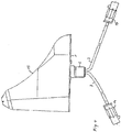
- the Fig. 2 shows the opposite side of the circuit board 4 with a grounded mobile zigzag slot radiator structure 12 for the purpose of radiator shortening. It is preferably a grounded structure, which is fed by the opposite radiator arrangement 6 using the printed circuit board dielectric. Networks for separate excitation of the slot structures are not required.
- the sections 62, 63 and 64 of the monopole radiator structure 6 are capable of forming the slot structures 12 and 13 in the desired manner, i. to feed in the frequency ranges realized here.
- the frequency ranges of the slot radiator antennas are determined by the length of the slot 12 on the one hand, i. in the low-frequency GSM area, and the slot 13 on the other hand, i. for the high-frequency GSM area, configurable.
- the mentioned zigzag slot radiator structure shortens the radiator length in the sense of a folded radiator.
- the respective impedance of the slot radiator is from the position of the exciter, see reference numeral 62 in FIG Fig. 1 , for the low-frequency slot radiator, and reference numeral 64 for the high-frequency slot radiator. Since the low-frequency and high-frequency GSM areas do not have to be decoupled, the monopole radiator structure 6 can be designed as a common exciter. The profile of the monopole radiator structure 6 according to the exemplary embodiment is optimized for an impedance of 50 ohms.
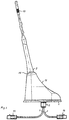
- the Fig. 3 shows a side view of the ready antenna with connecting leads 3 and Fakra plug-in devices 14.
- the radiator assemblies 6, 12 and 13 and the top of the support plate 1 are enclosed by the housing 15, consisting of a dielectric material.
- the Housing 15 may have a flow-optimized shape, eg in the so-called shark design.
- a receptacle 16 for the radiator 9 At the top of the housing 15 is a receptacle 16 for the radiator 9, which at its upper radiator end means for tuning 17, e.g. by extension or shortening of the radiator has.
- the radiator 9 is connected to the upper area 16 of the housing 15, e.g. fixed by screwing.
- the radiator 9 when not in use, the radiator 9 (see Fig. 4 ), without degrading the electrical characteristics of the GSM antennas.
Description
Die Erfindung betrifft eine Mehrbereichsantenne für eine Empfangs- und/oder Sendeeinrichtung für den mobilen Einsatz, insbesondere Kraftfahrzeugen, bestehend aus einer isolierenden Trägerplatte zur Aufnahme von elektrischen Anschlusselementen sowie zur Antennenmontage, wobei auf der Trägerplatte, sich von dieser im Wesentlichen senkrecht erstreckend, eine kupferkaschierte Leiterplatte angeordnet ist, sowie mit einem haubenartigen Gehäuse aus dielektrischem Material gemäß Oberbegriff des Anspruchs 1.The invention relates to a multigrade antenna for a receiving and / or transmitting device for mobile use, in particular motor vehicles, consisting of an insulating support plate for receiving electrical connection elements and antenna mounting, wherein on the support plate, extending from this substantially perpendicular, a copper-clad Circuit board is arranged, and with a hood-like housing of dielectric material according to the preamble of
Aus der
Bei dem stabförmigen Mehrbereichsstrahler nach
Monopolartige Antennen, insbesondere ausgebildet als Mehrband-Dachantennen für Fahrzeuge gemäß
Aus der
Bei der Antennenanordnung für den mobilen Betrieb nach
Bei allen Lösungen des geschilderten Standes der Technik wird für Mehrbereichsantennen der Einsatz von Sperrkreisen bzw. sogenannten Splittern erforderlich, um einen Anschluss für die jeweiligen Endgeräte zu realisieren.In all solutions of the described prior art for multi-range antennas, the use of blocking circuits or so-called Splitting required to realize a connection for the respective terminals.
Das Ausbilden derartiger diskreter Sperrkreise führt zu einem erhöhten schaltungstechnischen Aufwand und damit zu gestiegenen Kosten. Eine weitere Kraftfahrzeug-Antenne ist aus
Die Lösung der Aufgabe der Erfindung erfolgt durch die Merkmalskombination gemäß der Lehre nach Anspruch 1, wobei die Unteransprüche mindestens zweckmäßige Ausgestaltungen und Weiterbildungen darstellen.The object of the invention is achieved by the feature combination according to the teaching of
Es wird demnach von einer Mehrbereichsantenne für eine Empfangs- und/oder Sendeeinrichtung für den mobilen Einsatz, insbesondere Kraftfahrzeugen, ausgegangen. Die Mehrbereichsantenne besteht aus einer isolierenden Trägerplatte zur Aufnahme von elektrischen Anschlusselementen sowie zur Antennenmontage, insbesondere auf dem Dach eines Kraftfahrzeugs. Auf der Trägerplatte, sich von dieser im Wesentlichen senkrecht erstreckend, ist eine kupferkaschierte Leiterplatte angeordnet. Weiterhin ist die Mehrbereichsantenne von einem haubenartigen Gehäuse aus dielektrischem Material umgeben bzw. durch ein solches Gehäuse abgeschlossen.It is therefore assumed that a multi-range antenna for a receiving and / or transmitting device for mobile use, especially motor vehicles. The multigrade antenna consists of an insulating support plate for receiving electrical connection elements and for antenna mounting, in particular on the roof of a motor vehicle. On the support plate, extending from this substantially perpendicular, a copper-clad circuit board is arranged. Furthermore, the multi-region antenna is surrounded by a hood-like housing made of dielectric material or closed by such a housing.
Das Gehäuse kann mit Blick auf den bevorzugten Einsatz der Antenne bei Kraftfahrzeugen eine strömungsoptimierte Form, z.B. die Gestalt einer sogenannten Haifischflosse (shark design) besitzen.The housing may have a flow-optimized shape, e.g., in view of the preferred use of the antenna in motor vehicles. have the shape of a so-called shark fin.
Die elektrischen Anschlusselemente werden üblicherweise von der Unterseite der Trägerplatte in Richtung Fahrzeugdach geführt und von dort befindlichen Ausnehmungen aufgenommen.The electrical connection elements are usually guided from the underside of the carrier plate in the direction of the vehicle roof and received by recesses located there.
Der Grundgedanke der Erfindung besteht nun darin, die CB- (citizens band) und GSM- (global system for mobile communications) -Antennen bzw. Strahler räumlich voneinander zu trennen.The basic idea of the invention is to spatially separate the CB (citizens band) and GSM (global system for mobile communications) antennas.
Dabei ist die CB-Antenne als Stabstrahler ausgeführt. Der oder die GSM-Antennen werden separat als Monopole realisiert. Konkret werden die Monopole als Leiterplattenstrukturen erzeugt. Die Anschlussleitung, d.h. die Anschlussstruktur für den CB Stab, befindet sich auf einer bezogen auf die GSM-Strahler gemeinsamen Leiterplatte.The CB antenna is designed as a rod radiator. The one or more GSM antennas are realized separately as monopolies. Specifically, the monopolies are produced as printed circuit board structures. The connection line, i. the connection structure for the CB rod, is located on a common with respect to the GSM emitter PCB.
Es kommt insbesondere eine Leiterplatte mit beidseitig kupferkaschierten Strukturen zum Einsatz. Dabei kann es sich um eine Leiterplatte, bestehend aus einem Epoxid-Material, aber auch um eine Leiterplatte auf der Basis eines keramischen Trägers handeln. Unter kupferkaschierter Struktur sind auch derartige metallische, d.h. leitfähige Strukturen zu verstehen, welche eine andere metallische Basis, z.B. Nickel oder Edelmetalle, besitzen.In particular, a printed circuit board with structures laminated with copper on both sides is used. This may be a printed circuit board consisting of an epoxy material, but also a printed circuit board based on a ceramic carrier. Under copper-clad structure, such metallic, i. to understand conductive structures containing another metallic base, e.g. Nickel or precious metals.
Auf einer ersten Leiterplattenseite ist eine Mobilfunk-Monopolstrahlerstruktur und eine Anschlussflächenstruktur für den an der Oberseite des haubenartigen Gehäuses fixierbaren CB-Stabstrahler ausgebildet derart, dass das elektrische Feld zwischen der Anschlussflächenstruktur und der Monopolstrahlerstruktur orthogonal polarisiert ist, und zwar unter Beibehalten der räumlichen Trennung beider Strahler.On a first circuit board side, a mobile monopole radiator structure and a pad structure for the CB rod radiator fixable to the top of the hood-type housing are formed such that the electric field between the pad structure and the monopole radiator structure is orthogonally polarized while maintaining the spatial separation of both radiators ,
Auf der zweiten, der ersten gegenüberliegenden Leiterplattenseite ist eine geerdete Mobilfunk-Zick-Zack-Schlitzstrahlerstruktur ausgebildet, welche von der gegenüberliegenden Monopolstrahlerstruktur erregt wird.On the second, the first opposing circuit board side, a grounded mobile radio zig-zag slot radiator structure is formed, which is excited by the opposite monopole radiator structure.
Insbesondere durch letztgenannte Maßnahme lassen sich optimierte Antennen für unterschiedliche GSM-Frequenzbereiche in ein und derselben Antennenkonfiguration abdecken.The latter measure in particular makes it possible to cover optimized antennas for different GSM frequency ranges in one and the same antenna configuration.
Wie bereits erwähnt, kann für einen wahlweisen CB-Betrieb der Stabstrahler am haubenartigen Gehäuse durch Schrauben oder Stecken, mittels Bajonettverschluss oder in ähnlicher Weise befestigt werden. Diesbezüglich ist an der Oberseite des haubenartigen Gehäuses eine entsprechende Aufnahme für den Stabstrahler vorhanden.As previously mentioned, for optional CB operation, the rod radiator can be attached to the hood-like housing by screwing or plugging, by bayonet locking or the like. In this regard, a corresponding receptacle for the rod radiator is present at the top of the hood-like housing.
Der Stabstrahler weist an seinem Strahlerende Abstimmmittel, z.B. einen Abstimmstub oder ein verlänger- bzw. verkürzbares Strahlerende auf.The rod radiator has at its radiator end tuning means, e.g. a Abstimmstub or an extender or shortenable radiator end.
Die Leiterplatte mit den erfindungsgemäßen Strahler bzw. Anschlussstrukturen füllt die Längsschnittfläche des Gehäuses im Wesentlichen vollständig aus bzw. approximiert diese Fläche.The printed circuit board with the radiator or connecting structures according to the invention fills the longitudinal sectional area of the housing substantially completely or approximates this surface.
An einem im Betriebszustand im Wesentlichen horizontal ausgerichteten Außenrandbereich verläuft die Anschlussflächenstruktur für den CB-Strahler. Einem Teil dieser Struktur benachbart verläuft die Monopolstrahlerstruktur, wobei letztere über mindestens eine in der Leiterplattenebene orientierte Abwinklung oder Abknickung verfügt.At an operating state substantially horizontally oriented outer edge region extending the pad structure for the CB radiator. A part of this structure adjacent to the Monopolstrahlerstruktur runs, the latter has at least one oriented in the circuit board plane angling or kinking.
Die Anschlussflächenstruktur verläuft bis zur Oberseite der Leiterplatte und steht dort mit einem Kontaktelement in Verbindung, welches eine elektrische Kontaktierung zum CB-Stabstrahler herstellt.The pad structure extends to the top of the circuit board and is there in contact with a contact element, which produces an electrical contact with the CB rod radiator.
Die Erfindung soll nachstehend anhand eines Ausführungsbeispiels sowie unter Zuhilfenahme von Figuren näher erläutert werden.The invention will be explained below with reference to an embodiment and with the aid of figures.
Hierbei zeigen:
- Fig. 1
- die Mehrbereichsantenne mit Trägerplatte und Leiterplatte, und zwar in einer Ansicht auf die Mobilfunk-Monopolstrahlerstruktur mit Anschlussflächenstruktur für den in der
Fig. 1 noch nicht dargestellten Stabstrahler, wobei zur besseren Darstellbarkeit das haubenartige Gehäuse nicht gezeigt ist; - Fig. 2
- die Antenne analog
Fig. 1 von der gegenüberliegenden Seite mit der Mobilfunk-Zick-Zack-Schlitzstrahlerstruktur, ebenfalls ohne haubenartiges Gehäuse; - Fig. 3
- die komplette, mit haubenartigem Gehäuse und Stabstrahler versehene Antenne nebst Anschlusselementen sowie Bund zur Antennenmontage und
- Fig. 4
- die Mehrbereichsantenne analog
Fig. 3 mit entferntem Stabstrahler zum alleinigen Einsatz im GSM-Bereich.
- Fig. 1
- the multi-region antenna with support plate and circuit board, in a view of the mobile monopole radiator structure with pad structure for in the
Fig. 1 not shown rod radiator, wherein the hood-like housing is not shown for ease of illustration; - Fig. 2
- the antenna analog
Fig. 1 from the opposite side with the mobile zigzag slot radiator structure, also without hood-like housing; - Fig. 3
- the complete, provided with hood-like housing and rod radiator antenna, together with connecting elements and collar for antenna mounting and
- Fig. 4
- the multirange antenna analog
Fig. 3 with remote bar emitter for sole use in the GSM area.
Die im Ausführungsbeispiel wie folgt beschriebene Mehrbereichsantenne für den mobilen Einsatz, insbesondere für Kraftfahrzeuge, geht von einer Trägerplatte 1 aus, welche alle funktionswesentlichen Elemente und gegebenenfalls passive sowie elektronische Bauteile trägt.The described in the exemplary embodiment as described multi-range antenna for mobile use, in particular for motor vehicles, is based on a
An der Unterseite der Trägerplatte 1 befindet sich ein Anschlussbund 2, welcher im Montagezustand eine Ausnehmung z.B. in einem Kraftfahrzeugdach durchdringt. Im Inneren des Bundes 2 verlaufen bekannte Koaxanschlussleitungen 3 zu den jeweiligen Endgeräten.At the bottom of the
Sich von der Ebene der Trägerplatte 1 im Wesentlichen senkrecht, d.h. vertikal erstreckend, ist eine kupferkaschierte Leiterplatte 4 angeordnet.Extending substantially perpendicularly from the plane of the
Auf der ersten Leiterplattenseite 5 befindet sich eine Mobilfunk-Monopolstrahlerstruktur 6 und darüber hinaus eine Anschlussflächenstruktur 7.On the first
Die Anschlussflächenstruktur 7 reicht von einem unteren Bereich der Leiterplatte bis zu einem oberen Ende 8 und geht dort in einen Kontaktbereich über, der eine Verbindung zum entsprechenden Ende des Stabstrahlers 9 (siehe
Die Strukturen 6 und 7 sind so ausgebildet, dass das elektrische Feld orthogonal polarisiert ist. Beide Strahlerstrukturen sind räumlich getrennt.The
Hierdurch ergibt sich eine ausgezeichnete Entkopplung zwischen beiden Antennen im relevanten Funktionsbereich und es können separat zwei Dienste genutzt werden. Der Mobilfunk-Monopolstrahler ist am Anschlusspunkt 10 und der CB-Stabstrahler 9 am Anschlusspunkt 11 kontaktiert.This results in an excellent decoupling between the two antennas in the relevant functional area and it can be used separately two services. The mobile monopole radiator is contacted at the
Aus der Abbildung nach
Diese Abwinklung 62 geht in eine weitere Abwinklung 63 über, die im Wesentlichen die Richtung des Verlaufs der Struktur 61 aufnimmt. Dem Bereich 63 schließt sich eine weitere abgewinkelte Struktureinheit 64 an.This
Die Anschlussflächenstruktur 7 verläuft äußerst nahe des vertikalen Außenrands 71 der Leiterplatte 4. Zur Verbesserung der Entkopplung verlaufen die Bereiche 61 und 7 nicht parallel, sondern unter einem Winkel α.The
Die
Die Abschnitte 62, 63 und 64 der Monopolstrahlerstruktur 6 sind in der Lage, die Schlitzstrukturen 12 und 13 in der gewünschten Weise, d.h. in den hier realisierten Frequenzbereichen zu speisen.The
Die Frequenzbereiche der Schlitzstrahlerantennen sind durch die Länge des Schlitzes 12 einerseits, d.h. in dem niederfrequenten GSM-Bereich, und des Schlitzes 13 andererseits, d.h. für den hochfrequenten GSM-Bereich, ausgestaltbar. Die erwähnte Zick-Zack-Schlitzstrahlerstruktur verkürzt die Strahlerlänge im Sinne eines gefalteten Strahlers.The frequency ranges of the slot radiator antennas are determined by the length of the
Die jeweilige Impedanz des Schlitzstrahlers ist von der Position der Erreger, siehe Bezugszeichen 62 in
Die
An der Oberseite des Gehäuses 15 befindet sich eine Aufnahme 16 für den Strahler 9, der an seinem oberen Strahlerende Mittel zur Abstimmung 17, z.B. durch Verlängerung oder Verkürzung des Strahlers aufweist.At the top of the
Wird zusätzlich zum GSM-Betrieb die Antennenanordnung für den Betrieb eines CB-Funkgeräts genutzt, wird der Strahler 9 am oberen Bereich 16 des Gehäuses 15, z.B. durch Einschrauben fixiert.If, in addition to the GSM operation, the antenna arrangement is used for the operation of a CB radio, the
Ebenso ist aber bei Nichtgebrauch der Strahler 9 (siehe
Claims (4)
- A multi range antenna for a mobile receiver and/or transmitter in particular for motor vehicles, the multi range antenna comprising:an insulating carrier plate (1) for receiving electrical connection elements and for mounting the multi range antenna wherein a printed circuit board (4) is arranged on the carrier plate (1) and essentially extends perpendicular to the carrier plate (1), and a hood shaped housing (15) made from dielectric material,wherein a mobile radio mono pole radiator structure (6) and a contact surface structure (7) for a CB rod radiator (9) that is attachable at a top side of the hood shaped housing (15) are arranged on a first carrier plate side (5) wherein the contact surface structure (7) and the mono pole radiator structure (6) are configured so that the electrical field is polarized orthogonal and both radiators are separated spatially and decoupled,wherein the printed circuit board (4) includes copper plated structures and a grounded mobile radio zig zag slot radiator structure (12) is configured on a second printed circuit board side (51) that is arranged opposite to the first printed circuit board side (5) wherein the grounded mobile radio zig zag slot radiator structure (12) is excited by the mono pole radiator structure (6), furthermore the circuit board (4) essentially approximates and fills a longitudinal sectional surface of the housing (15), wherein the connection surface structure (7) for the CB radiator extends in an outer edge portion (71) of the printed circuit board (4) which outer edge portion is substantially vertical in an operating condition and the mono pole radiator structure extends adjacent to a portion of this structure starting from a lower portion of the printed circuit board (4) in a vertical direction (61),wherein at least one elbow (62; 63; 64) adjoins in this vertical arrangement of the mono pole radiator structure wherein the at least one elbow is oriented in the printed circuit board plane.
- The multi range antenna according to claim 1, wherein the rod radiator (9) is attachable at the hood shaped housing (15) by bolting, plug in or similar for optional CB operations.
- The multi range antenna according to claim 2, wherein the rod radiator (9) includes a tuning device (17) at a rod radiator end.
- The multi range antenna according to one of the preceding claims, wherein the connection surface structure (7) extends up to a top side of the printed circuit board (4) and is connected at this location with a contact portion or contact element (8) which provides an electrical contact with the CB rod radiator (9).
Applications Claiming Priority (3)
| Application Number | Priority Date | Filing Date | Title |
|---|---|---|---|
| DE202014001466 | 2014-02-18 | ||
| DE202014002207.0U DE202014002207U1 (en) | 2014-02-18 | 2014-03-10 | Multi-range antenna for a receiving and / or transmitting device for mobile use |
| PCT/EP2015/052752 WO2015124463A1 (en) | 2014-02-18 | 2015-02-10 | Multi-range antenna for a receiver and/or transmitter device for mobile use |
Publications (3)
| Publication Number | Publication Date |
|---|---|
| EP3108535A1 EP3108535A1 (en) | 2016-12-28 |
| EP3108535B1 true EP3108535B1 (en) | 2017-12-27 |
| EP3108535B8 EP3108535B8 (en) | 2018-08-01 |
Family
ID=50556370
Family Applications (1)
| Application Number | Title | Priority Date | Filing Date |
|---|---|---|---|
| EP15705002.2A Active EP3108535B8 (en) | 2014-02-18 | 2015-02-10 | Multi-range antenna for a receiver and/or transmitter device for mobile use |
Country Status (3)
| Country | Link |
|---|---|
| EP (1) | EP3108535B8 (en) |
| DE (1) | DE202014002207U1 (en) |
| WO (1) | WO2015124463A1 (en) |
Families Citing this family (5)
| Publication number | Priority date | Publication date | Assignee | Title |
|---|---|---|---|---|
| DE202014008788U1 (en) | 2014-10-13 | 2014-11-27 | Antennentechnik Bad Blankenburg Gmbh | Multi-band fin antenna for mobile use, especially for vehicles |
| DE202015001905U1 (en) | 2014-12-12 | 2015-05-11 | Antennentechnik Bad Blankenburg Gmbh | Short-rod monopole antenna for use in the mobile sector |
| JP6402154B2 (en) * | 2016-09-16 | 2018-10-10 | 株式会社フジクラ | Antenna device and in-vehicle antenna device |
| JP6401835B1 (en) | 2017-08-07 | 2018-10-10 | 株式会社ヨコオ | Antenna device |
| DE202018101775U1 (en) | 2018-03-13 | 2018-04-16 | Antennentechnik Abb Bad Blankenburg Gmbh | Multi-range antenna for a receiving and / or transmitting device for mobile use, in particular vehicles, consisting of a double-sided copper-clad circuit board |
Family Cites Families (11)
| Publication number | Priority date | Publication date | Assignee | Title |
|---|---|---|---|---|
| DE4141783B4 (en) | 1991-01-31 | 2004-04-15 | Fuba Automotive Gmbh & Co. Kg | Motor vehicle antenna for several separate frequency ranges |
| DE4102845B4 (en) | 1991-01-31 | 2004-02-19 | Fuba Automotive Gmbh & Co. Kg | Motor vehicle rod antenna for several separate frequency ranges |
| DE4109630A1 (en) | 1991-03-23 | 1992-09-24 | Bosch Gmbh Robert | ROD-SHAPED MULTI-RANGE EMITTER |
| FR2727250A1 (en) * | 1994-11-22 | 1996-05-24 | Brachat Patrice | MONOPOLY BROADBAND ANTENNA IN UNIPLANAR PRINTED TECHNOLOGY AND TRANSMITTING AND / OR RECEIVING DEVICE INCORPORATING SUCH ANTENNA |
| CN1307743C (en) * | 2001-02-26 | 2007-03-28 | 日本安特尼株式会社 | Multifrequency antenna |
| DE10207703B4 (en) | 2002-02-22 | 2005-06-09 | Kathrein-Werke Kg | Antenna for a receiving and / or transmitting device, in particular as a roof antenna for motor vehicles |
| DE102005054286B4 (en) | 2005-11-11 | 2011-04-07 | Delphi Delco Electronics Europe Gmbh | antenna array |
| ITVI20050300A1 (en) * | 2005-11-11 | 2007-05-12 | Calearo Antenne Spa | VEHICLE MULTI BAND ANTENNA FOR MOBILE TELEPHONY |
| DE102007061740B4 (en) | 2007-12-20 | 2022-12-01 | Robert Bosch Gmbh | Multi-area antenna and method |
| TWI483464B (en) * | 2011-10-20 | 2015-05-01 | Acer Inc | Communication device and antenna structure therein |
| JP5961027B2 (en) * | 2012-04-13 | 2016-08-02 | 株式会社日本自動車部品総合研究所 | Antenna device |
-
2014
- 2014-03-10 DE DE202014002207.0U patent/DE202014002207U1/en not_active Expired - Lifetime
-
2015
- 2015-02-10 EP EP15705002.2A patent/EP3108535B8/en active Active
- 2015-02-10 WO PCT/EP2015/052752 patent/WO2015124463A1/en active Application Filing
Also Published As
| Publication number | Publication date |
|---|---|
| DE202014002207U1 (en) | 2014-04-09 |
| WO2015124463A1 (en) | 2015-08-27 |
| EP3108535B8 (en) | 2018-08-01 |
| EP3108535A1 (en) | 2016-12-28 |
Similar Documents
| Publication | Publication Date | Title |
|---|---|---|
| EP1829158B1 (en) | Disc-monopole antenna structure | |
| DE60315791T2 (en) | chip antenna | |
| EP1619752B1 (en) | Antenna module | |
| DE60023062T2 (en) | antenna design | |
| EP0952625B1 (en) | Antenna for several radio communications services | |
| DE102005060648B4 (en) | Antenna device with radiation characteristics suitable for ultra wide band communication | |
| EP3108535B1 (en) | Multi-range antenna for a receiver and/or transmitter device for mobile use | |
| DE102005047418B4 (en) | Multi-band antenna device, wireless data transmission device and radio frequency chip | |
| DE19713929A1 (en) | Transmitting and receiving antenna system | |
| DE102005015561A1 (en) | Broadband internal antenna for mobile communication terminal, has radiator with conductive stripline through which current flows to form current paths in different directions to set certain broadband using electromagnetic coupling | |
| DE10150149A1 (en) | Antenna module for automobile mobile radio antenna has antenna element spaced above conductive base plate and coupled to latter via short-circuit path | |
| DE102008007258A1 (en) | Multi-band antenna and mobile communication terminal, which has these | |
| DE10205358A1 (en) | Meandering dual band antenna | |
| DE102015220372B3 (en) | Multiband GNSS antenna | |
| DE19961488A1 (en) | Antenna for communications terminal has a relatively large bandwidth and can be manufactured cheaply and reproducibly | |
| DE112008001688T5 (en) | Antenna system for the remote control of an application in the automotive sector | |
| DE60105447T2 (en) | PRINTED PATCH ANTENNA | |
| DE102012207954A1 (en) | antenna device | |
| DE102007055327A1 (en) | External multi-band radio antenna module | |
| EP2367233A1 (en) | Planar antenna system | |
| EP1619751A1 (en) | Wideband antenna of low profile | |
| DE60033140T2 (en) | Multi-frequency band antenna | |
| DE102010036600A1 (en) | Dual-band antenna | |
| DE19722506A1 (en) | Radio | |
| EP1033821B1 (en) | DECT transceiver module |
Legal Events
| Date | Code | Title | Description |
|---|---|---|---|
| PUAI | Public reference made under article 153(3) epc to a published international application that has entered the european phase |
Free format text: ORIGINAL CODE: 0009012 |
|
| 17P | Request for examination filed |
Effective date: 20150806 |
|
| AK | Designated contracting states |
Kind code of ref document: A1 Designated state(s): AL AT BE BG CH CY CZ DE DK EE ES FI FR GB GR HR HU IE IS IT LI LT LU LV MC MK MT NL NO PL PT RO RS SE SI SK SM TR |
|
| AX | Request for extension of the european patent |
Extension state: BA ME |
|
| 17Q | First examination report despatched |
Effective date: 20170215 |
|
| DAX | Request for extension of the european patent (deleted) | ||
| GRAP | Despatch of communication of intention to grant a patent |
Free format text: ORIGINAL CODE: EPIDOSNIGR1 |
|
| INTG | Intention to grant announced |
Effective date: 20170802 |
|
| GRAA | (expected) grant |
Free format text: ORIGINAL CODE: 0009210 |
|
| GRAS | Grant fee paid |
Free format text: ORIGINAL CODE: EPIDOSNIGR3 |
|
| AK | Designated contracting states |
Kind code of ref document: B1 Designated state(s): AL AT BE BG CH CY CZ DE DK EE ES FI FR GB GR HR HU IE IS IT LI LT LU LV MC MK MT NL NO PL PT RO RS SE SI SK SM TR |
|
| REG | Reference to a national code |
Ref country code: GB Ref legal event code: FG4D Free format text: NOT ENGLISH |
|
| REG | Reference to a national code |
Ref country code: CH Ref legal event code: EP |
|
| REG | Reference to a national code |
Ref country code: AT Ref legal event code: REF Ref document number: 959042 Country of ref document: AT Kind code of ref document: T Effective date: 20180115 |
|
| REG | Reference to a national code |
Ref country code: IE Ref legal event code: FG4D Free format text: LANGUAGE OF EP DOCUMENT: GERMAN |
|
| REG | Reference to a national code |
Ref country code: DE Ref legal event code: R096 Ref document number: 502015002701 Country of ref document: DE |
|
| PG25 | Lapsed in a contracting state [announced via postgrant information from national office to epo] |
Ref country code: NO Free format text: LAPSE BECAUSE OF FAILURE TO SUBMIT A TRANSLATION OF THE DESCRIPTION OR TO PAY THE FEE WITHIN THE PRESCRIBED TIME-LIMIT Effective date: 20180327 Ref country code: FI Free format text: LAPSE BECAUSE OF FAILURE TO SUBMIT A TRANSLATION OF THE DESCRIPTION OR TO PAY THE FEE WITHIN THE PRESCRIBED TIME-LIMIT Effective date: 20171227 Ref country code: LT Free format text: LAPSE BECAUSE OF FAILURE TO SUBMIT A TRANSLATION OF THE DESCRIPTION OR TO PAY THE FEE WITHIN THE PRESCRIBED TIME-LIMIT Effective date: 20171227 |
|
| REG | Reference to a national code |
Ref country code: NL Ref legal event code: MP Effective date: 20171227 |
|
| REG | Reference to a national code |
Ref country code: LT Ref legal event code: MG4D |
|
| PG25 | Lapsed in a contracting state [announced via postgrant information from national office to epo] |
Ref country code: GR Free format text: LAPSE BECAUSE OF FAILURE TO SUBMIT A TRANSLATION OF THE DESCRIPTION OR TO PAY THE FEE WITHIN THE PRESCRIBED TIME-LIMIT Effective date: 20180328 Ref country code: LV Free format text: LAPSE BECAUSE OF FAILURE TO SUBMIT A TRANSLATION OF THE DESCRIPTION OR TO PAY THE FEE WITHIN THE PRESCRIBED TIME-LIMIT Effective date: 20171227 Ref country code: HR Free format text: LAPSE BECAUSE OF FAILURE TO SUBMIT A TRANSLATION OF THE DESCRIPTION OR TO PAY THE FEE WITHIN THE PRESCRIBED TIME-LIMIT Effective date: 20171227 Ref country code: BG Free format text: LAPSE BECAUSE OF FAILURE TO SUBMIT A TRANSLATION OF THE DESCRIPTION OR TO PAY THE FEE WITHIN THE PRESCRIBED TIME-LIMIT Effective date: 20180327 Ref country code: RS Free format text: LAPSE BECAUSE OF FAILURE TO SUBMIT A TRANSLATION OF THE DESCRIPTION OR TO PAY THE FEE WITHIN THE PRESCRIBED TIME-LIMIT Effective date: 20171227 |
|
| GRAT | Correction requested after decision to grant or after decision to maintain patent in amended form |
Free format text: ORIGINAL CODE: EPIDOSNCDEC |
|
| PG25 | Lapsed in a contracting state [announced via postgrant information from national office to epo] |
Ref country code: NL Free format text: LAPSE BECAUSE OF FAILURE TO SUBMIT A TRANSLATION OF THE DESCRIPTION OR TO PAY THE FEE WITHIN THE PRESCRIBED TIME-LIMIT Effective date: 20171227 |
|
| RAP2 | Party data changed (patent owner data changed or rights of a patent transferred) |
Owner name: ANTENNENTECHNIK ABB BAD BLANKENBURG GMBH |
|
| PG25 | Lapsed in a contracting state [announced via postgrant information from national office to epo] |
Ref country code: CZ Free format text: LAPSE BECAUSE OF FAILURE TO SUBMIT A TRANSLATION OF THE DESCRIPTION OR TO PAY THE FEE WITHIN THE PRESCRIBED TIME-LIMIT Effective date: 20171227 Ref country code: ES Free format text: LAPSE BECAUSE OF FAILURE TO SUBMIT A TRANSLATION OF THE DESCRIPTION OR TO PAY THE FEE WITHIN THE PRESCRIBED TIME-LIMIT Effective date: 20171227 Ref country code: SK Free format text: LAPSE BECAUSE OF FAILURE TO SUBMIT A TRANSLATION OF THE DESCRIPTION OR TO PAY THE FEE WITHIN THE PRESCRIBED TIME-LIMIT Effective date: 20171227 Ref country code: CY Free format text: LAPSE BECAUSE OF FAILURE TO SUBMIT A TRANSLATION OF THE DESCRIPTION OR TO PAY THE FEE WITHIN THE PRESCRIBED TIME-LIMIT Effective date: 20171227 Ref country code: EE Free format text: LAPSE BECAUSE OF FAILURE TO SUBMIT A TRANSLATION OF THE DESCRIPTION OR TO PAY THE FEE WITHIN THE PRESCRIBED TIME-LIMIT Effective date: 20171227 |
|
| PG25 | Lapsed in a contracting state [announced via postgrant information from national office to epo] |
Ref country code: IS Free format text: LAPSE BECAUSE OF FAILURE TO SUBMIT A TRANSLATION OF THE DESCRIPTION OR TO PAY THE FEE WITHIN THE PRESCRIBED TIME-LIMIT Effective date: 20180427 Ref country code: PL Free format text: LAPSE BECAUSE OF FAILURE TO SUBMIT A TRANSLATION OF THE DESCRIPTION OR TO PAY THE FEE WITHIN THE PRESCRIBED TIME-LIMIT Effective date: 20171227 Ref country code: IT Free format text: LAPSE BECAUSE OF FAILURE TO SUBMIT A TRANSLATION OF THE DESCRIPTION OR TO PAY THE FEE WITHIN THE PRESCRIBED TIME-LIMIT Effective date: 20171227 Ref country code: SM Free format text: LAPSE BECAUSE OF FAILURE TO SUBMIT A TRANSLATION OF THE DESCRIPTION OR TO PAY THE FEE WITHIN THE PRESCRIBED TIME-LIMIT Effective date: 20171227 |
|
| REG | Reference to a national code |
Ref country code: DE Ref legal event code: R081 Ref document number: 502015002701 Country of ref document: DE Owner name: ANTENNENTECHNIK BAD BLANKENBURG GMBH, DE Free format text: FORMER OWNER: ANTENNENTECHNIK BAD BLANKENBURG GMBH, 07422 BAD BLANKENBURG, DE Ref country code: DE Ref legal event code: R082 Ref document number: 502015002701 Country of ref document: DE Representative=s name: MEISSNER BOLTE PATENTANWAELTE RECHTSANWAELTE P, DE |
|
| REG | Reference to a national code |
Ref country code: CH Ref legal event code: PL |
|
| PG25 | Lapsed in a contracting state [announced via postgrant information from national office to epo] |
Ref country code: MT Free format text: LAPSE BECAUSE OF FAILURE TO SUBMIT A TRANSLATION OF THE DESCRIPTION OR TO PAY THE FEE WITHIN THE PRESCRIBED TIME-LIMIT Effective date: 20171227 Ref country code: MC Free format text: LAPSE BECAUSE OF FAILURE TO SUBMIT A TRANSLATION OF THE DESCRIPTION OR TO PAY THE FEE WITHIN THE PRESCRIBED TIME-LIMIT Effective date: 20171227 |
|
| REG | Reference to a national code |
Ref country code: DE Ref legal event code: R097 Ref document number: 502015002701 Country of ref document: DE |
|
| PLBE | No opposition filed within time limit |
Free format text: ORIGINAL CODE: 0009261 |
|
| STAA | Information on the status of an ep patent application or granted ep patent |
Free format text: STATUS: NO OPPOSITION FILED WITHIN TIME LIMIT |
|
| REG | Reference to a national code |
Ref country code: IE Ref legal event code: MM4A |
|
| REG | Reference to a national code |
Ref country code: BE Ref legal event code: MM Effective date: 20180228 |
|
| PG25 | Lapsed in a contracting state [announced via postgrant information from national office to epo] |
Ref country code: LU Free format text: LAPSE BECAUSE OF NON-PAYMENT OF DUE FEES Effective date: 20180210 Ref country code: CH Free format text: LAPSE BECAUSE OF NON-PAYMENT OF DUE FEES Effective date: 20180228 Ref country code: LI Free format text: LAPSE BECAUSE OF NON-PAYMENT OF DUE FEES Effective date: 20180228 Ref country code: DK Free format text: LAPSE BECAUSE OF FAILURE TO SUBMIT A TRANSLATION OF THE DESCRIPTION OR TO PAY THE FEE WITHIN THE PRESCRIBED TIME-LIMIT Effective date: 20171227 |
|
| REG | Reference to a national code |
Ref country code: FR Ref legal event code: ST Effective date: 20181031 |
|
| 26N | No opposition filed |
Effective date: 20180928 |
|
| PG25 | Lapsed in a contracting state [announced via postgrant information from national office to epo] |
Ref country code: IE Free format text: LAPSE BECAUSE OF NON-PAYMENT OF DUE FEES Effective date: 20180210 |
|
| PG25 | Lapsed in a contracting state [announced via postgrant information from national office to epo] |
Ref country code: BE Free format text: LAPSE BECAUSE OF NON-PAYMENT OF DUE FEES Effective date: 20180228 Ref country code: SI Free format text: LAPSE BECAUSE OF FAILURE TO SUBMIT A TRANSLATION OF THE DESCRIPTION OR TO PAY THE FEE WITHIN THE PRESCRIBED TIME-LIMIT Effective date: 20171227 Ref country code: FR Free format text: LAPSE BECAUSE OF NON-PAYMENT OF DUE FEES Effective date: 20180228 |
|
| GBPC | Gb: european patent ceased through non-payment of renewal fee |
Effective date: 20190210 |
|
| PG25 | Lapsed in a contracting state [announced via postgrant information from national office to epo] |
Ref country code: GB Free format text: LAPSE BECAUSE OF NON-PAYMENT OF DUE FEES Effective date: 20190210 |
|
| REG | Reference to a national code |
Ref country code: DE Ref legal event code: R081 Ref document number: 502015002701 Country of ref document: DE Owner name: DESAY SV AUTOMOTIVE EUROPE GMBH, DE Free format text: FORMER OWNER: ANTENNENTECHNIK ABB BAD BLANKENBURG GMBH, 99428 WEIMAR, DE Ref country code: DE Ref legal event code: R082 Ref document number: 502015002701 Country of ref document: DE Representative=s name: MEISSNER BOLTE PATENTANWAELTE RECHTSANWAELTE P, DE Ref country code: DE Ref legal event code: R081 Ref document number: 502015002701 Country of ref document: DE Owner name: ANTENNENTECHNIK BAD BLANKENBURG GMBH, DE Free format text: FORMER OWNER: ANTENNENTECHNIK ABB BAD BLANKENBURG GMBH, 99428 WEIMAR, DE |
|
| PG25 | Lapsed in a contracting state [announced via postgrant information from national office to epo] |
Ref country code: TR Free format text: LAPSE BECAUSE OF FAILURE TO SUBMIT A TRANSLATION OF THE DESCRIPTION OR TO PAY THE FEE WITHIN THE PRESCRIBED TIME-LIMIT Effective date: 20171227 |
|
| PG25 | Lapsed in a contracting state [announced via postgrant information from national office to epo] |
Ref country code: PT Free format text: LAPSE BECAUSE OF FAILURE TO SUBMIT A TRANSLATION OF THE DESCRIPTION OR TO PAY THE FEE WITHIN THE PRESCRIBED TIME-LIMIT Effective date: 20171227 |
|
| PG25 | Lapsed in a contracting state [announced via postgrant information from national office to epo] |
Ref country code: MK Free format text: LAPSE BECAUSE OF NON-PAYMENT OF DUE FEES Effective date: 20171227 Ref country code: RO Free format text: LAPSE BECAUSE OF FAILURE TO SUBMIT A TRANSLATION OF THE DESCRIPTION OR TO PAY THE FEE WITHIN THE PRESCRIBED TIME-LIMIT Effective date: 20171227 Ref country code: HU Free format text: LAPSE BECAUSE OF FAILURE TO SUBMIT A TRANSLATION OF THE DESCRIPTION OR TO PAY THE FEE WITHIN THE PRESCRIBED TIME-LIMIT; INVALID AB INITIO Effective date: 20150210 Ref country code: SE Free format text: LAPSE BECAUSE OF FAILURE TO SUBMIT A TRANSLATION OF THE DESCRIPTION OR TO PAY THE FEE WITHIN THE PRESCRIBED TIME-LIMIT Effective date: 20171227 |
|
| PG25 | Lapsed in a contracting state [announced via postgrant information from national office to epo] |
Ref country code: AL Free format text: LAPSE BECAUSE OF FAILURE TO SUBMIT A TRANSLATION OF THE DESCRIPTION OR TO PAY THE FEE WITHIN THE PRESCRIBED TIME-LIMIT Effective date: 20171227 |
|
| REG | Reference to a national code |
Ref country code: AT Ref legal event code: HC Ref document number: 959042 Country of ref document: AT Kind code of ref document: T Owner name: ANTENNENTECHNIK BAD BLANKENBURG GMBH, DE Effective date: 20200618 |
|
| PGFP | Annual fee paid to national office [announced via postgrant information from national office to epo] |
Ref country code: AT Payment date: 20230215 Year of fee payment: 9 |
|
| PGFP | Annual fee paid to national office [announced via postgrant information from national office to epo] |
Ref country code: DE Payment date: 20230227 Year of fee payment: 9 |
|
| P01 | Opt-out of the competence of the unified patent court (upc) registered |
Effective date: 20230530 |
|
| REG | Reference to a national code |
Ref country code: DE Ref legal event code: R081 Ref document number: 502015002701 Country of ref document: DE Owner name: DESAY SV AUTOMOTIVE EUROPE GMBH, DE Free format text: FORMER OWNER: ANTENNENTECHNIK BAD BLANKENBURG GMBH, 99428 WEIMAR, DE |