EP3108430B1 - Behälter - Google Patents
Behälter Download PDFInfo
- Publication number
- EP3108430B1 EP3108430B1 EP14714542.9A EP14714542A EP3108430B1 EP 3108430 B1 EP3108430 B1 EP 3108430B1 EP 14714542 A EP14714542 A EP 14714542A EP 3108430 B1 EP3108430 B1 EP 3108430B1
- Authority
- EP
- European Patent Office
- Prior art keywords
- flowable substance
- container
- closure
- porous element
- opening
- Prior art date
- Legal status (The legal status is an assumption and is not a legal conclusion. Google has not performed a legal analysis and makes no representation as to the accuracy of the status listed.)
- Active
Links
- 239000000126 substance Substances 0.000 claims description 255
- 230000009969 flowable effect Effects 0.000 claims description 250
- 239000003205 fragrance Substances 0.000 claims description 53
- 239000012530 fluid Substances 0.000 claims description 34
- 239000003599 detergent Substances 0.000 claims description 8
- 239000002979 fabric softener Substances 0.000 claims description 6
- 239000002324 mouth wash Substances 0.000 claims description 4
- 229940051866 mouthwash Drugs 0.000 claims description 4
- 239000000551 dentifrice Substances 0.000 claims description 3
- 238000004851 dishwashing Methods 0.000 claims description 3
- 239000000344 soap Substances 0.000 claims description 3
- 239000004033 plastic Substances 0.000 description 11
- 229920003023 plastic Polymers 0.000 description 11
- 239000000853 adhesive Substances 0.000 description 9
- 230000001070 adhesive effect Effects 0.000 description 9
- 239000000796 flavoring agent Substances 0.000 description 7
- 239000000463 material Substances 0.000 description 6
- 235000013355 food flavoring agent Nutrition 0.000 description 5
- 239000007788 liquid Substances 0.000 description 5
- 230000013011 mating Effects 0.000 description 5
- 239000011148 porous material Substances 0.000 description 5
- NOOLISFMXDJSKH-UTLUCORTSA-N (+)-Neomenthol Chemical compound CC(C)[C@@H]1CC[C@@H](C)C[C@@H]1O NOOLISFMXDJSKH-UTLUCORTSA-N 0.000 description 3
- 241000723347 Cinnamomum Species 0.000 description 3
- NOOLISFMXDJSKH-UHFFFAOYSA-N DL-menthol Natural products CC(C)C1CCC(C)CC1O NOOLISFMXDJSKH-UHFFFAOYSA-N 0.000 description 3
- 235000017803 cinnamon Nutrition 0.000 description 3
- 229940041616 menthol Drugs 0.000 description 3
- 239000000203 mixture Substances 0.000 description 3
- 239000004743 Polypropylene Substances 0.000 description 2
- 230000002745 absorbent Effects 0.000 description 2
- 239000002250 absorbent Substances 0.000 description 2
- 239000003795 chemical substances by application Substances 0.000 description 2
- 150000001875 compounds Chemical class 0.000 description 2
- 235000019634 flavors Nutrition 0.000 description 2
- 238000002955 isolation Methods 0.000 description 2
- 238000004519 manufacturing process Methods 0.000 description 2
- 230000004048 modification Effects 0.000 description 2
- 238000012986 modification Methods 0.000 description 2
- 239000011087 paperboard Substances 0.000 description 2
- 229920000139 polyethylene terephthalate Polymers 0.000 description 2
- 239000005020 polyethylene terephthalate Substances 0.000 description 2
- -1 polypropylene Polymers 0.000 description 2
- 229920001155 polypropylene Polymers 0.000 description 2
- 230000000717 retained effect Effects 0.000 description 2
- 230000000052 comparative effect Effects 0.000 description 1
- 230000001419 dependent effect Effects 0.000 description 1
- 239000000839 emulsion Substances 0.000 description 1
- 239000006260 foam Substances 0.000 description 1
- 230000005484 gravity Effects 0.000 description 1
- 230000000873 masking effect Effects 0.000 description 1
- 230000007246 mechanism Effects 0.000 description 1
- 238000006386 neutralization reaction Methods 0.000 description 1
- 238000004806 packaging method and process Methods 0.000 description 1
- 239000002304 perfume Substances 0.000 description 1
- 239000000843 powder Substances 0.000 description 1
- 238000007789 sealing Methods 0.000 description 1
- 230000009291 secondary effect Effects 0.000 description 1
Images


Classifications
-
- B—PERFORMING OPERATIONS; TRANSPORTING
- B65—CONVEYING; PACKING; STORING; HANDLING THIN OR FILAMENTARY MATERIAL
- B65D—CONTAINERS FOR STORAGE OR TRANSPORT OF ARTICLES OR MATERIALS, e.g. BAGS, BARRELS, BOTTLES, BOXES, CANS, CARTONS, CRATES, DRUMS, JARS, TANKS, HOPPERS, FORWARDING CONTAINERS; ACCESSORIES, CLOSURES, OR FITTINGS THEREFOR; PACKAGING ELEMENTS; PACKAGES
- B65D51/00—Closures not otherwise provided for
- B65D51/24—Closures not otherwise provided for combined or co-operating with auxiliary devices for non-closing purposes
-
- A—HUMAN NECESSITIES
- A61—MEDICAL OR VETERINARY SCIENCE; HYGIENE
- A61L—METHODS OR APPARATUS FOR STERILISING MATERIALS OR OBJECTS IN GENERAL; DISINFECTION, STERILISATION OR DEODORISATION OF AIR; CHEMICAL ASPECTS OF BANDAGES, DRESSINGS, ABSORBENT PADS OR SURGICAL ARTICLES; MATERIALS FOR BANDAGES, DRESSINGS, ABSORBENT PADS OR SURGICAL ARTICLES
- A61L9/00—Disinfection, sterilisation or deodorisation of air
- A61L9/015—Disinfection, sterilisation or deodorisation of air using gaseous or vaporous substances, e.g. ozone
- A61L9/04—Disinfection, sterilisation or deodorisation of air using gaseous or vaporous substances, e.g. ozone using substances evaporated in the air without heating
- A61L9/12—Apparatus, e.g. holders, therefor
-
- A—HUMAN NECESSITIES
- A45—HAND OR TRAVELLING ARTICLES
- A45D—HAIRDRESSING OR SHAVING EQUIPMENT; EQUIPMENT FOR COSMETICS OR COSMETIC TREATMENTS, e.g. FOR MANICURING OR PEDICURING
- A45D34/00—Containers or accessories specially adapted for handling liquid toiletry or cosmetic substances, e.g. perfumes
-
- A—HUMAN NECESSITIES
- A61—MEDICAL OR VETERINARY SCIENCE; HYGIENE
- A61L—METHODS OR APPARATUS FOR STERILISING MATERIALS OR OBJECTS IN GENERAL; DISINFECTION, STERILISATION OR DEODORISATION OF AIR; CHEMICAL ASPECTS OF BANDAGES, DRESSINGS, ABSORBENT PADS OR SURGICAL ARTICLES; MATERIALS FOR BANDAGES, DRESSINGS, ABSORBENT PADS OR SURGICAL ARTICLES
- A61L9/00—Disinfection, sterilisation or deodorisation of air
- A61L9/01—Deodorant compositions
- A61L9/014—Deodorant compositions containing sorbent material, e.g. activated carbon
-
- A—HUMAN NECESSITIES
- A61—MEDICAL OR VETERINARY SCIENCE; HYGIENE
- A61L—METHODS OR APPARATUS FOR STERILISING MATERIALS OR OBJECTS IN GENERAL; DISINFECTION, STERILISATION OR DEODORISATION OF AIR; CHEMICAL ASPECTS OF BANDAGES, DRESSINGS, ABSORBENT PADS OR SURGICAL ARTICLES; MATERIALS FOR BANDAGES, DRESSINGS, ABSORBENT PADS OR SURGICAL ARTICLES
- A61L9/00—Disinfection, sterilisation or deodorisation of air
- A61L9/015—Disinfection, sterilisation or deodorisation of air using gaseous or vaporous substances, e.g. ozone
- A61L9/04—Disinfection, sterilisation or deodorisation of air using gaseous or vaporous substances, e.g. ozone using substances evaporated in the air without heating
-
- B—PERFORMING OPERATIONS; TRANSPORTING
- B65—CONVEYING; PACKING; STORING; HANDLING THIN OR FILAMENTARY MATERIAL
- B65D—CONTAINERS FOR STORAGE OR TRANSPORT OF ARTICLES OR MATERIALS, e.g. BAGS, BARRELS, BOTTLES, BOXES, CANS, CARTONS, CRATES, DRUMS, JARS, TANKS, HOPPERS, FORWARDING CONTAINERS; ACCESSORIES, CLOSURES, OR FITTINGS THEREFOR; PACKAGING ELEMENTS; PACKAGES
- B65D25/00—Details of other kinds or types of rigid or semi-rigid containers
- B65D25/38—Devices for discharging contents
- B65D25/40—Nozzles or spouts
- B65D25/42—Integral or attached nozzles or spouts
-
- A—HUMAN NECESSITIES
- A45—HAND OR TRAVELLING ARTICLES
- A45D—HAIRDRESSING OR SHAVING EQUIPMENT; EQUIPMENT FOR COSMETICS OR COSMETIC TREATMENTS, e.g. FOR MANICURING OR PEDICURING
- A45D34/00—Containers or accessories specially adapted for handling liquid toiletry or cosmetic substances, e.g. perfumes
- A45D2034/002—Accessories
-
- A—HUMAN NECESSITIES
- A61—MEDICAL OR VETERINARY SCIENCE; HYGIENE
- A61L—METHODS OR APPARATUS FOR STERILISING MATERIALS OR OBJECTS IN GENERAL; DISINFECTION, STERILISATION OR DEODORISATION OF AIR; CHEMICAL ASPECTS OF BANDAGES, DRESSINGS, ABSORBENT PADS OR SURGICAL ARTICLES; MATERIALS FOR BANDAGES, DRESSINGS, ABSORBENT PADS OR SURGICAL ARTICLES
- A61L9/00—Disinfection, sterilisation or deodorisation of air
- A61L9/015—Disinfection, sterilisation or deodorisation of air using gaseous or vaporous substances, e.g. ozone
- A61L9/04—Disinfection, sterilisation or deodorisation of air using gaseous or vaporous substances, e.g. ozone using substances evaporated in the air without heating
- A61L9/12—Apparatus, e.g. holders, therefor
- A61L9/127—Apparatus, e.g. holders, therefor comprising a wick
Definitions
- the present invention relates to a container, such as a bottle, for storing a flowable substance, such as a personal care product or a home care product, which has a fragrance.
- WO 01/23274 A1 describes a package to contain or store liquid detergent compositions which comprises a bottle with a hollow body for storing a liquid and a dispensing opening. The opening may be sealed by a closure which also may have an open position for dispensing the liquid from the bottle.
- a perfume-impregnated plastic member in form of an annular disk may be disposed adjacent to the opening between the closure and a finish of the bottle, wherein the annular disk includes a perfume composition which effectively suppresses malodors, which diffuse out of the liquid detergent compositions by neutralization, modification, or masking.
- the perfume-impregnated plastic member may be also be provided in the form of a cylindrical sleeve disposed within the finish such that an inner surface of the sleeve is exposed to a head space of a bottle.
- US 2002/139093 A1 describes a system of dispensing scent into a consumable product.
- the system involves packaging the consumable product in a container and sealing the container with a cap assembly including one section of scented plastic that contains a scented compound and, when the container is sealed with the cap assembly, is left exposed to the contents of the container.
- the scent from the scented compound may leach out of the plastic and into the contents of the container.
- the consumable product in the container passively acquires the scent of the scented plastic.
- a sleeve insert may be made of the scented plastic and inserted between a cap and bottle.
- a neck extension may be manufactured from the scented plastic, the neck extension having an area in the interior thereof which is exposed to the contents of a bottle.
- a cap liner may be made of scented plastic and placed between a cap and another container so as to be exposed to the contents of said container.
- DE 20 2005 002986 U1 relates to a dispenser and polisher for storing and applying creme-like products which comprises a cylindrical container having a shaft disposed therein, the shaft being able to axially move a piston head so as to transport the product towards an application member.
- the application member may be formed from a sponge-like material.
- a container comprising an improved system for delivering to a user a fragrance of a flowable substance in a chamber of a container.
- the present invention provides a container according to independent claim 1. Preferred embodiments are defined by the dependent claims.
- a container may define a chamber storing a volume of a flowable substance having a fragrance and defining an opening through which the flowable substance is dispensable from the chamber; the container comprising a porous element for retaining a quantity of the flowable substance, the porous element being at a position relative to the volume of the flowable substance so that the flowable substance comes into contact with the porous element as a result of the flowable substance being dispensed from the chamber through the opening.
- the container comprises a vessel defining the chamber; a body defining the opening; and optionally a closure movable relative to the vessel between a first position at which the closure isolates the opening from an exterior of the container and a second position at which the opening is not isolated from the exterior of the container by the closure, the closure comprising the porous element.
- the container comprises a vessel defining the chamber; and a body defining the opening, the body comprising the porous element.
- a further container not according to the invention may comprise: a vessel defining a chamber for storing a volume of a flowable substance having a fragrance; and a body defining an opening through which the flowable substance is dispensable from the chamber, the body comprising a porous element for retaining a quantity of the flowable substance.
- the opening is partially or fully defined by the porous element.
- the body comprises a member and the porous element is affixed to the member. Further optionally, the opening is partially or fully defined by the member.
- the porous element comprises a liner affixed to the member.
- the porous element partially or fully surrounds the opening.
- either of the containers comprises a closure movable relative to the vessel between a first position at which the closure isolates the opening from an exterior of the container and a second position at which the opening is not isolated from the exterior of the container by the closure.
- a further container not according to the invention may comprise: a vessel defining a chamber for storing a volume of a flowable substance having a fragrance; a body defining an opening through which the flowable substance is dispensable from the chamber; and a closure movable relative to the vessel between a first position at which the closure isolates the opening from an exterior of the container and a second position at which the opening is not isolated from the exterior of the container by the closure , the closure comprising a porous element for retaining a quantity of the flowable substance.
- the closure comprises a closure member, and the porous element is affixed to the closure member or is unitary with the closure member. Further optionally, the closure is movable relative to the vessel between the first position at which at least a portion of the porous member is in the opening and the second position at which none of the porous element is in the opening.
- the porous element forms a seal isolating an interior of the closure from an exterior of the container when the closure is at the first position relative to the vessel. Further optionally, the porous element is compressed between the closure and one of the body and the vessel when the closure is at the first position relative to the vessel.
- the porous element is in fluid communication with the chamber when the closure is at the first position relative to the vessel.
- the porous element is isolated from the chamber when the closure is at the first position, and the porous element is in fluid communication with the chamber when the closure is at the second position.
- the porous element is isolated from an exterior of the container when the closure is at the first position, and the porous element is in fluid communication with the exterior of the container when the closure is at the second position.
- the porous element partially or fully surrounds the body when the closure is at the first position.
- one or more apertures extend through the closure , each of the one or more apertures being in fluid communication with the porous element when the closure is at the first position relative to the vessel.
- the container comprises a seal on the exterior of the closure, wherein the seal is movable relative to the closure between a first position at which the seal isolates the, or each, of the one or more apertures from an exterior of the container and a second position at which the seal does not isolate the, or each, of the one or more apertures from the exterior of the container.
- the body is affixed to the vessel.
- the opening is defined by a spout.
- the porous element is absorbent.
- the porous element comprises one or more of a wick, sintered plastic, pulp material, screen material, and pressed paperboard.
- the flowable substance is one of a personal care product and a homecare product.
- the personal care product is one of a hand soap, a dentifrice, a hair care product, a body wash, and a mouthwash.
- the home care product is one of a laundry detergent, a dish washing detergent, a fabric softener, a fabric conditioner, a floor cleaner, and a surface cleaner.
- ranges are used as shorthand for describing each and every value that is within the range. Any value within the range can be selected as the terminus of the range.
- the container 100 comprises a vessel 110 defining a chamber 112 storing a volume of a flowable substance 114 having a fragrance, a body 120 defining an opening 122 through which the flowable substance is dispensable from the chamber 112 and the container 100, and a closure 130 for selectively isolating the opening 122 from an exterior of the container 100.
- a vessel 110 defining a chamber 112 storing a volume of a flowable substance 114 having a fragrance
- a body 120 defining an opening 122 through which the flowable substance is dispensable from the chamber 112 and the container 100
- a closure 130 for selectively isolating the opening 122 from an exterior of the container 100.
- the vessel 110 includes a base 111 for supporting stably standing the container 100 on a horizontal support surface 5.
- the base 111 comprises a planar, annular contact portion lying in a first plane P 1 -P 1 for stably standing the vessel 110 and the rest of the container 100 on the horizontal support surface 5.
- the base 111 comprises a planar, non-annular contact portion lying in the first plane P 1 -P 1 .
- the base 111 may comprise a circular, elliptical, or polygonal contact portion.
- the base 111 comprises a plurality of contact portions lying in the first plane P 1 -P 1 .
- the base 111 comprises one or more non-planar contact portions lying in the first plane P 1 -P 1 , such as one or more point apexes or line apexes that are each a portion of a curved or non-planar surface of the vessel 110, yet the combination of the contact portion(s) of the base 111 enables the container 100 to stand stably on the horizontal support surface 5.
- Other configurations of contact portion(s) of the base 111 will be apparent to the skilled person.
- the vessel 110 defines the chamber 112 storing the volume of the flowable substance 114.
- flowable substance it is meant a substance that is able to flow at room temperature and atmospheric pressure.
- room temperature it is meant a temperature of 20 degrees Celsius
- atmospheric pressure it is meant a pressure of 101 kPa.
- the flowable substance preferably is a liquid, although it could instead be any one of a paste, a powder, a gel, a foam, an emulsion and a sol.
- the flowable substance 114 may have the fragrance as a result of the flowable substance 114 comprising a fragrant agent.
- the fragrant agent may be included in the flowable substance 114 to give the flowable substance 114 the fragrance.
- the flowable substance 114 may have the fragrance as a result of the flowable substance 114 comprising a flavoring agent, which flavoring agent has a fragrance.
- the flavoring agent may be included in the flowable substance 114 primarily to give the flowable substance 114 a flavor, yet a secondary effect of the provision of the flavoring agent is to give the flowable substance 114 the fragrance.
- the fragrance e.g.
- the flowable substance 114 may comprise a flavoring agent such as menthol or cinnamon, which primarily gives the flowable substance 114 a menthol or cinnamon flavor or taste but also gives the flowable substance 114 a menthol or cinnamon fragrance or smell.
- menthol or cinnamon primarily gives the flowable substance 114 a menthol or cinnamon flavor or taste but also gives the flowable substance 114 a menthol or cinnamon fragrance or smell.
- the flowable substance 114 is manufactured, when provided in the chamber 112, the flowable substance 114 has a fragrance or smell detectable by the human nose.
- the vessel 110 is opaque. In variations to this embodiment, the vessel 110 may be partially, or fully, translucent or transparent, to allow a user to see how much flowable substance 114 remains in the chamber 112.
- a second portion 117 of the vessel 110 is a neck 117 surrounding and defining an orifice 118, which orifice 118 has a smaller cross-sectional area parallel to the first plane P 1 -P 1 than the chamber 112.
- the orifice 118 is at an interior of the neck 117 and is in fluid communication with the chamber 112.
- the vessel 110 is made from non-porous material, which in the illustrated embodiment is polypropylene (PP) but in other embodiments may be polyethylene terephthalate (PET) or another non-porous material, so that the only path from the chamber 112 to an exterior of the vessel 110 and the container 100 is via the orifice 118.
- An exterior surface of the neck 117 comprises a male screw thread 119 for connecting the closure 130 to the vessel 110, as will be described below.
- the body 120 and more specifically a first portion 124 of the body 120, is affixed to the vessel 110.
- the first portion 124 of the body 120 is located in the orifice 118 defined by the neck 117 of the vessel 110 and is affixed to the neck 117 of the vessel 110.
- the first portion 124 of the body 120 is affixed to the neck 117 of the vessel 110 by an adhesive.
- the first portion 124 of the body 120 may be affixed to the neck 117 of the vessel 110 in any other way, such as by any of a welded portion common to the body 120 and the vessel 110 (that is, the first portion 124 of the body 120 is welded to the neck 117 of the vessel 110), cooperating engagement members (such as screw threads) of the neck 117 and the first portion 124 of the body 120, a snap-fit connection, and an interference fit of the first portion 124 of the body 120 in the orifice 118.
- the body 120 is not detachable from the vessel 110, at least by an end user. However, in some embodiments, the body 120 may be detachably attached to the vessel 110.
- a second portion 126 of the body 120 defines a spout 126 defining the opening 122 through which the flowable substance 114 is dispensable from the chamber 112 and the container 100. Accordingly, the opening 122 is fully defined by the body 120, so that the body 120 fully surrounds the opening 122, and the opening 122 is in fluid communication with the chamber 112 of the vessel 110. In the illustrated embodiment, the opening 122 is inclined relative to the first plane P 1 -P 1 . In variations to the illustrated embodiment, the opening 122 is parallel to the first plane P 1 -P 1 . In the illustrated embodiment, the second portion 126 of the body 120 is unitary with the first portion 124 of the body 120.
- the body 120 comprising the first and second portions 124, 126, is an integrally-formed single component.
- the body 120 i.e. the first and second portions 124, 126 of the body 120 together, is a porous element 120 that is suitable for retaining a quantity of the flowable substance 114.
- porous it is meant having one or more pores, voids or interstices into, or through which, fluid, such as the flowable substance, is able to flow.
- the porous element specifically is configured to be suitable for retaining the flowable substance in one or more of the pores, voids or interstices of the porous element.
- the body 120 is absorbent and, in the illustrated embodiment, is made from a sintered plastic.
- the body 120 may be made from wicking material, sintered plastic, pulp material, screen material, pressed paperboard, or another porous material.
- the first portion 124 of the body 120 is not porous, whereas the second portion 126 of the body 120, which is unitary with the first portion 124 of the body 120, is a porous element that is suitable for retaining a quantity of the flowable substance 114.
- the closure 130 is movable relative to the vessel 110 and the body 120 between a first position (not shown), at which the closure 130 isolates the opening 122, the chamber 112 and the volume of flowable substance 114 therein from the exterior of the container 100, and a second position (see Figure 1 ), at which the opening 122, the chamber 112 and the volume of flowable substance 114 therein are in fluid communication with the exterior of the container 100.
- a first position not shown
- the closure 130 when the closure 130 is at its first position relative to the vessel 110, the closure 130 does not block the opening 122 but still isolates the opening 122 from the exterior of the container 100.
- the isolation is provided by a portion, such as a rim, of the closure 130 mating with the vessel 110 to create a seal therebetween.
- the isolation may, at least in part, be provided by the female screw thread 139 (discussed below) mating with the male screw thread 119.
- the closure 130 does block the opening 122 when the closure 130 is at its first position relative to the vessel 110.
- the closure 130 is a screw cap with a female screw thread 139 for mating with the male screw thread 119 at the exterior surface of the neck 117 of the vessel 110.
- the closure 130 is movable relative to the vessel 110 between the first and second positions by rotating the closure 130 relative to the vessel 110 to engage and disengage the screw threads 119, 139, as required.
- the closure 130 comprises a floor 131a and a skirt 131b extending from the floor 131a.
- the female screw thread 139 is provided on an interior face of the skirt 131b.
- the vessel 110, body 120 and closure 130 may be suitably modified from the embodiment of Figure 1 so that the screw thread 139 of the closure 130 is male and the screw thread 119 of the vessel 110 is female and mateable with the screw thread 139 of the closure 130.
- the closure 130 may be detachably connectable to the vessel 110 using mechanisms other than cooperating screw threads. In such other variations to the illustrated embodiment, the screw threads 119, 139 maybe omitted.
- the closure 130 when the closure 130 is at the first position (not shown) relative to the vessel 110, the body 120 is in fluid communication with the chamber 112 and the volume of flowable substance 114 therein, but the body 120 is isolated from the exterior of the container 100.
- the closure 130 when the closure 130 is at the second position relative to the vessel 110 (as shown), the body 120 is in fluid communication with the chamber 112 and the volume of flowable substance 114 therein, and with the exterior of the container 100.
- the closure 130 when the closure 130 is at the second position relative to the vessel 110, the closure 130 is disconnected from the vessel 110.
- the closure 130 when the closure 130 is at the second position relative to the vessel 110, the closure 130 may remain connected to the vessel 110, for example by a hinge, such as a living hinge formed integrally with the closure 130 and the vessel 110.
- the container 100 When the container 100 is in a storage state with the closure 130 at its first position relative to the vessel 110 and with the base 111 of the vessel 110 in contact with the horizontal support surface 5 and the plane P 1 -P 1 parallel to the horizontal support surface 5, although the body 120 is in fluid communication with the chamber 112 and the volume of the flowable substance 114 in the chamber 112, the body 120 is out of contact with the volume of the flowable substance 114 in the chamber 112. That is, an uppermost surface 115 of the flowable substance 114 in the chamber 112 is between the plane P 1 -P 1 and the body 120 but out of contact with the body 120.
- the flowable substance 114 comes into contact with the body 120. Since the body 120 is porous, when the flowable substance 114 comes into contact with the body 120, the body 120 retains a quantity of the flowable substance 114. Accordingly, when a potential purchaser subsequently moves the closure 130 to its second position relative to the vessel 110 and sniffs the opening 122 to determine the fragrance of the flowable substance 114, the fragrance is delivered not only through the opening 122 from the volume of the flowable substance 114 within the chamber 112 but also from the body 120 itself.
- a greater surface area is provided from which the fragrance is deliverable to a user.
- the porous element captures, or becomes infused with, the flowable substance 114 and its fragrance either by simple contact with the flowable substance 114 or by capillary action as a result of coming into contact with the flowable substance 114.
- a potential purchaser is thus able to determine accurately the fragrance of the flowable substance 114 prior to purchasing the container 100.
- the body 120 is at a position relative to the volume of the flowable substance 114 so that the flowable substance 114 comes into contact with the body 120 as a result of the flowable substance 114 being dispensed from the chamber 112 through the opening 122. More specifically, the body 120 is at a position relative to the volume of the flowable substance 114 so that the flowable substance 114 comes into contact with the body 120 as the flowable substance 114 is dispensed from the chamber 112 through the opening 122. That is, the body 120 is on a flow path extending between the chamber 112 and the opening 122.
- the flowable substance 114 comes into contact with the body 120, and the body 120 retains a quantity of the flowable substance 114. Therefore, even if, over time, some of the flowable substance 114 retained by the body 120 moves from the body 120 to the chamber 112 under the influence of gravity, at every dispensing operation the body 120 is recharged with a quantity of the flowable substance 114. Accordingly, throughout the working lifetime of the container 100, i.e. while some of the flowable substance 114 remains in the container 100 and a user repeatedly dispenses some of the flowable substance 114, the user is able to sniff the opening 122 to determine accurately the fragrance of the flowable substance 114.
- FIG. 2 Another embodiment of a container of the present invention will now be described with reference to Figure 2 .
- Like elements in Figures 1 and 2 have like reference numerals and will not be described again for conciseness. Any of the above-described possible variations to the preceding described container may be made to the container of Figure 2 .
- the container 200 of Figure 2 differs from the container 100 of Figure 1 only in the form of the body 120.
- the second portion 126 of the body 120 which second portion 126 defines the spout, is not unitary with the first portion 124 of the body 120. Instead, the second portion 126 of the body 120 is affixed to the first portion 124 of the body 120 by an adhesive.
- the second portion 126 of the body 120 may be affixed to the first portion 124 of the body 120 in any other way, such as by any of a welded portion common to the first and second portions 124, 126 of the body 120, cooperating engagement members (such as screw threads) first and second portions 124, 126 of the body 120, a snap-fit connection, and an interference fit of the second portion 126 of the body 120 in the first portion 124 of the body 120.
- cooperating engagement members such as screw threads
- the first portion 124 of the body 120 is a non-porous member, whereas the second portion 126 of the body 120 is a porous element that is suitable for retaining a quantity of the flowable substance 114.
- the opening 122 is fully defined by the second portion 126 of the body 120, and the second portion 126 of the body 120 fully surrounds the opening 122.
- the second portion 126 of the body 120 is a non-porous member, whereas the first portion 124 of the body 120 is porous and is an element that is suitable for retaining a quantity of the flowable substance 114.
- the opening 122 is fully defined by the second portion 126 of the body 120, i.e. by the member, yet the first portion 124 of the body 120 fully surrounds the opening 122.
- each of the first and second portions 124, 126 of the body 120 is porous and is an element that is suitable for retaining a quantity of the flowable substance 114.
- the container 200 of Figure 2 is operable in a similar manner to container 100 of Figure 1 .
- the second portion 126 of the body 120 is in fluid communication with the chamber 112 and the volume of the flowable substance 114 in the chamber 112, yet the second portion 126 of the body 120 is out of contact with the volume of the flowable substance 114 in the chamber 112.
- the container 200 is tilted sufficiently relative to the horizontal during transportation to a retailer, or when being put on a shelf in a retailer's shop or store, the flowable substance 114 comes into contact with the second portion 126 of the body 120 and the second portion 126 of the body 120 retains a quantity of the flowable substance 114.
- a fragrance of the flowable substance 114 is delivered not only through the opening 122 from the volume of the flowable substance 114 within the chamber 112 but also from the second portion 126 of the body 120.
- a potential purchaser or a user is able to sniff the opening 122 to determine accurately the fragrance of the flowable substance 114.
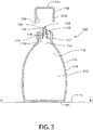
- FIG. 3 Another embodiment of a container of the present invention will now be described with reference to Figure 3 .
- Like elements in Figures 1 and 3 have like reference numerals and will not be described again for conciseness. Any of the above-described possible variations to the preceding described containers may be made to the container of Figure 3 .
- the container 300 of Figure 3 differs from the container 100 of Figure 1 only in the form of the body 120.
- the first and second portions 124, 126 of the body 120 are unitary and together form a non-porous member, and the body 120 comprises a third portion 128.
- the third portion 128 of the body 120 is an annular porous element that is suitable for retaining a quantity of the flowable substance 114.
- the opening 122 is fully defined by the third portion 128 of the body 120, each of the second and third portions 126, 128 of the body 120 fully surround the opening 122, and the second and third portions 126, 128 of the body 120 together define the spout.
- the third portion 128 of the body 120 is a liner affixed to a radially inner surface of the second portion 126 of the body 120, i.e. to the member, preferably by an adhesive.
- the third portion 128 of the body 120 is not annular and only partially surrounds the opening 122.
- the opening 122 is partially defined by the member and partially defined by the third portion 128 of the body 120.
- the third portion 128 of the body 120 is not a liner but nevertheless still is affixed to the radially inner surface of the member.
- the container 300 of Figure 3 is operable in a similar manner to container 100 of Figure 1 .
- the container 300 When the container 300 is in a storage state with the closure 130 at its first position relative to the vessel 110, the third portion 128 of the body 120 is in fluid communication with the chamber 112 and the volume of the flowable substance 114 in the chamber 112, yet the third portion 128 of the body 120 is out of contact with the volume of the flowable substance 114 in the chamber 112.
- the container 300 is tilted sufficiently relative to the horizontal during transportation to a retailer, or when being put on a shelf in a retailer's shop or store, the flowable substance 114 comes into contact with the third portion 128 of the body 120 and the third portion 128 of the body 120 retains a quantity of the flowable substance 114.
- a fragrance of the flowable substance 114 is delivered not only through the opening 122 from the volume of the flowable substance 114 within the chamber 112 but also from the third portion 128 of the body 120.
- a potential purchaser or a user is able to sniff the opening 122 to determine accurately the fragrance of the flowable substance 114.
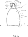
- the container 400 of Figures 4a and 4b differs from the container 300 of Figure 3 only in the form of the body 120.
- the first and second portions 124, 126 of the body 120 are unitary and together form a non-porous member
- the third portion 128 of the body 120 is a liner affixed to a radially outer surface of the second portion 126 of the body 120, i.e. to the member, preferably by an adhesive.
- the third portion 128 of the body 120 still is an annular porous element that is suitable for retaining a quantity of the flowable substance 114.
- the opening 122 is fully defined by the second portion 126 of the body 120, each of the second and third portions 126, 128 of the body 120 fully surround the opening 122, and the second and third portions 126, 128 of the body 120 together define the spout.
- the third portion 128 of the body 120 is not annular and only partially surrounds the opening 122.
- the third portion 128 of the body 120 is not a liner but nevertheless still is affixed to the radially outer surface of the member.
- the porous element i.e. the third portion 128 of the body 120
- the third portion 128 of the body 120 is in fluid communication with the chamber 112 and the volume of flowable substance 114 therein, and also with the exterior of the container 400.
- the body 120 and closure 130 are relatively shaped so that, when the closure 130 is at the first position relative to the vessel 110, the porous element, i.e. the third portion 128 of the body 120, is in fluid communication with the chamber 112 and the volume of flowable substance 114 therein.
- the container 400 of Figures 4a and 4b is operable in a slightly different manner to containers 100, 200, 300 of Figures 1 to 3 .
- the closure 130 is at its first position relative to the vessel 110 (see Figure 4b )
- the closure 130 prevents the flowable substance 114 from coming into contact with the third portion 128 of the body 120.
- the closure 130 when the closure 130 is at its second position relative to the vessel 110, after a user has tilted the container 400 sufficiently relative to the horizontal to dispense the flowable substance 114 from the chamber 112 through the opening 122 and has subsequently returned the container 400 back towards its original position relative to the horizontal, some of the flowable substance 114 remaining at the opening 122 will run down the radial outside surface of the body 120, i.e. will come into contact with the third portion 128 of the body 120. Thus, the third portion 128 of the body 120 would retain a quantity of the flowable substance 114.
- a fragrance of the flowable substance 114 is delivered not only through the opening 122 from the volume of the flowable substance 114 within the chamber 112 but also from the third portion 128 of the body 120.
- a user is able to sniff around the opening 122 to determine accurately the fragrance of the flowable substance 114.
- the third portion 128 of the body 120 is not at a position relative to the volume of the flowable substance 114 so that the flowable substance 114 comes into contact with the third portion 128 of the body 120 as the flowable substance 114 is dispensed from the chamber 112 through the opening 122. That is, the third portion 128 of the body 120 is not on a flow path extending between the chamber 112 and the opening 122.
- the third portion 128 of the body 120 is at a position relative to the volume of the flowable substance 114 so that the flowable substance 114 comes into contact with the third portion 128 of the body 120 as a result of the flowable substance 114 being dispensed from the chamber 112 through the opening 122.
- FIG. 5a and 5b Another example useful for understanding the container of the present invention is shown in Figures 5a and 5b .
- Like elements in Figures 4a , 4b , 5a and 5b have like reference numerals and will not be described again for conciseness. Any of the above-described possible variations to the preceding described containers may be made to the container of Figures 5a and 5b .
- the container 500 of Figures 5a and 5b differs from the container 400 of Figures 4a and 4b only in the form of the third portion 128 of the body 120.
- the third portion 128 of the body 120 is affixed to both the first and second portions 124, 126 of the body 120, i.e. to the member, preferably by an adhesive.
- the third portion 128 of the body 120 still is an annular porous element that is suitable for retaining a quantity of the flowable substance 114.
- the opening 122 is fully defined by the second portion 126 of the body 120, the second portion 126 of the body 120 fully surrounds the opening 122, and the second portion 126 of the body 120 defines the spout.
- the third portion 128 of the body 120 is not annular.
- the porous element i.e. the third portion 128 of the body 120
- the third portion 128 of the body 120 is in fluid communication with the chamber 112 and the volume of flowable substance 114 therein, and also with the exterior of the container 500.
- the body 120 and closure 130 are relatively shaped so that, when the closure 130 is at the first position relative to the vessel 110 , the porous element, i.e. the third portion 128 of the body 120, is in fluid communication with the chamber 112 and the volume of flowable substance 114 therein.
- the container 500 of Figures 5a and 5b is operable in the same manner as the container 400 of Figures 4a and 4b . Accordingly, it will be appreciated that, in the container 500 of Figures 5a and 5b , the third portion 128 of the body 120 is not at a position relative to the volume of the flowable substance 114 so that the flowable substance 114 comes into contact with the third portion 128 of the body 120 as the flowable substance 114 is dispensed from the chamber 112 through the opening 122.
- the third portion 128 of the body 120 is at a position relative to the volume of the flowable substance 114 so that the flowable substance 114 comes into contact with the third portion 128 of the body 120 as a result of the flowable substance 114 being dispensed from the chamber 112 through the opening 122.
- FIG. 6a and 6b An example of a container is shown in Figures 6a and 6b .
- Like elements in Figures 5a , 5b , 6a and 6b have like reference numerals and will not be described again for conciseness. Any of the above-described possible variations to the preceding described containers may be made to the container of Figures 6a and 6b .
- the container 600 of Figures 6a and 6b differs from the container 500 of Figures 5a and 5b only in the location of the porous element for retaining a quantity of the flowable substance 114.
- the porous element for retaining a quantity of the flowable substance 114 is comprised in the closure 130 rather than in the body 120.
- the body 120 comprising the first and second portions 124, 126, which are unitary, is a non-porous member.
- the opening 122 is fully defined by the second portion 126 of the body 120, the second portion 126 of the body 120 fully surrounds the opening 122, and the second portion 126 of the body 120 defines the spout.
- the body 120 is free of any porous element for retaining a quantity of the flowable substance 114.
- the container 600 may comprise any of the porous elements discussed above and shown in Figures 1 to 6b in the body 120, as well as the porous element 132 comprised in the closure 130.
- the closure 130 comprises a closure member 131, in the form of a screw cap, and the porous element 132 is affixed to the closure member 131, preferably by adhesive.
- the porous element 132 is unitary with the closure member 131.
- the closure member 131 comprises a floor 131a and a skirt 131b depending from the floor 131a.
- the female screw thread 139 is provided on an interior face of the skirt 131b.
- the porous element 132 is an elongate element affixed to the floor 131a of the closure member 131 so that the porous element 132 is elongate in a direction extending from the floor 131a and the skirt 131b surrounds the porous element 132.
- the skirt 131b and the porous element 132 are spaced apart.
- the porous element 132 is dimensioned so as to be able to fit in the opening 122 defined by the body 120.
- the closure 130 is movable relative to the vessel 110 between a first position (see Figure 6b ) at which a portion of the porous element 132 of the closure 130 is in the opening 122 and the closure 130 blocks the opening 122, and a second position (see Figure 6a ) at which none of the porous element 132 is in the opening 122 and the opening 122 is not blocked by the closure 130.
- a first position see Figure 6b
- a second position see Figure 6a
- the closure 130 when the closure 130 is at the first position relative to the vessel 110, the porous element 132 blocks the opening 122.
- the closure 130 when the closure 130 is at the first position relative to the vessel 110, at least a portion of the porous element 132 is in the opening 122 but the closure 130, including the porous element 132, does not block the opening 122.
- the porous element 132 when the closure 130 is at the first position relative to the vessel 110, the porous element 132 is in fluid communication with the chamber 112 and the volume of flowable substance 114 therein, but the porous element 132 is isolated from the exterior of the container 600.
- the porous element 132 when the closure 130 is at the second position relative to the vessel 110, the porous element 132 is in fluid communication with the chamber 112 and the volume of flowable substance 114 therein, and with the exterior of the container 600.
- the container 600 is shown in a storage state with the base 111 of the vessel 110 in contact with the horizontal support surface 5 and the plane P 1 -P 1 parallel to the horizontal support surface 5.
- the porous element 132 is in fluid communication with the chamber 112 and the volume of the flowable substance 114 in the chamber 112
- the porous element 132 is out of contact with the volume of the flowable substance 114 in the chamber 112. That is, an uppermost surface 115 of the flowable substance 114 in the chamber 112 is between the plane P 1 -P 1 and the porous element 132 but out of contact with the porous element 132.
- the flowable substance 114 comes into contact with the porous element 132, and the porous element 132 retains a quantity of the flowable substance 114. Accordingly, when a potential purchaser subsequently moves the closure 130 to its second position relative to the vessel 110 and sniffs to determine the fragrance of the flowable substance 114, the fragrance is delivered not only through the opening 122 from the volume of the flowable substance 114 within the chamber 112 but also from the porous element 132 of the closure 130. A potential purchaser is thus able to determine accurately the fragrance of the flowable substance 114 prior to purchase of the container 600.
- Improved delivery of the fragrance continues after a user has purchased the container 600.
- the container 600 is tilted sufficiently relative to the horizontal during transportation around the user's residence, the flowable substance 114 comes into contact with the porous element 132, and the porous element 132 retains a quantity of the flowable substance 114.
- the closure 130 is at its second position relative to the vessel 110, after a user has tilted the container 600 sufficiently relative to the horizontal to dispense the flowable substance 114 from the chamber 112 through the opening 122 and has subsequently returned the container 600 back towards its original position relative to the horizontal, a residual volume of the flowable substance 114 will remain on a surface of the second portion 126 of the body 120 at the opening 122.
- the porous element 132 When the user subsequently returns the closure 130 to its first position relative to the vessel 110, the porous element 132 would come into contact with the residual volume of the flowable substance 114, and the porous element 132 would retain a quantity of the flowable substance 114. Therefore, at least at every dispensing operation, the porous element 132 is recharged with a quantity of the flowable substance 114. Accordingly, throughout the working lifetime of the container 600, i.e. while some of the flowable substance 114 remains in the container 600 and a user repeatedly dispenses some of the flowable substance 114, the user is able to sniff the closure 130 to determine accurately the fragrance of the flowable substance 114.
- the porous element 132 is not at a position relative to the volume of the flowable substance 114 so that the flowable substance 114 comes into contact with the porous element 132 as the flowable substance 114 is dispensed from the chamber 112 through the opening 122.
- the porous element 132 is at a position relative to the volume of the flowable substance 114 so that the flowable substance 114 comes into contact with porous element 132 as a result of the flowable substance 114 being dispensed from the chamber 112 through the opening 122.
- FIG. 7a and 7b Another example of a container is shown in Figures 7a and 7b .
- Like elements in Figures 6a , 6b , 7a and 7b have like reference numerals and will not be described again for conciseness. Any of the above-described possible variations to the preceding described containers may be made to the container of Figures 7a and 7b .
- the container 700 of Figures 7a and 7b differs from the container 600 of Figures 6a and 6b only in the location of the porous element for retaining a quantity of the flowable substance 114.
- the closure 130 of the container 700 of Figures 7a and 7b comprises a closure member 131 of the same form as the closure member 131 of the container 600 of Figures 6a and 6b , and the porous element 132 again is affixed to the closure member 131, preferably by adhesive.
- the porous element 132 is unitary with the closure member 131.
- the porous element 132 is an annular element affixed to the floor 131a of the closure member 131 so that the skirt 131b surrounds the porous element 132.
- the closure 130 is movable relative to the vessel 110 between a first position (see Figure 7b ) at which the closure 130 isolates the opening 122 from an exterior of the container 700 but the opening 122 is in fluid communication with the porous element 132, and a second position (see Figure 7a ) at which the opening 122 is in fluid communication with the exterior of the container 700 and the porous element 132.
- the body 120 and closure 130 are relatively shaped so that, when the closure 130 is at the first position relative to the vessel 110, the porous element 132 is isolated from the opening 122, the chamber 112 and the volume of flowable substance 114 therein. When the closure 130 is at the first position relative to the vessel 110, the porous element 132 fully surrounds the body 120.
- the porous element 132 is not annular and may only partially surround the body 120.
- the porous element 132 is in fluid communication with the chamber 112 and the volume of flowable substance 114 therein, and with the exterior of the container 700.
- the closure 1 30 When the closure 1 30 is at its second position relative to the vessel 110, after a user has tilted the container 700 sufficiently relative to the horizontal to dispense the flowable substance 114 from the chamber 112 through the opening 122 and into the closure member 131, so as to measure out a volume of the flowable substance 114, some of the flowable substance 114 will come into contact with the porous element 132. Thus, again the porous element 132 would retain a quantity of the flowable substance 114. The user can then pour the measured volume of the flowable substance 114 from the closure member 131 into its desired destination.
- a fragrance of the flowable substance 114 is delivered not only through the opening 122 from the volume of the flowable substance 114 within the chamber 112 but also from the porous element 132 of the closure 130.
- a user is able to sniff to determine accurately the fragrance of the flowable substance 114.
- the closure 130 is subsequently returned to its first position relative to the vessel 110, the porous element 132 is again isolated from the exterior of the container 700.
- the porous element 132 is not at a position relative to the volume of the flowable substance 114 so that the flowable substance 114 comes into contact with the porous element 132 as the flowable substance 114 is dispensed from the chamber 112 through the opening 122.
- the porous element 132 is at a position relative to the volume of the flowable substance 114 so that the flowable substance 114 comes into contact with the porous element 132 as a result of the flowable substance 114 being dispensed from the chamber 112 through the opening 122.
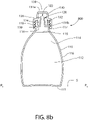
- FIG. 8a and 8b Another example of a container is shown in Figures 8a and 8b .
- Like elements in Figures 7a , 7b , 8a and 8b have like reference numerals and will not be described again for conciseness. Any of the above-described possible variations to the preceding described containers may be made to the container of Figures 8a and 8b .
- the container 800 of Figures 8a and 8b differs from the container 700 of Figures 7a and 7b only in the form of the closure member 131 and the location of the porous element for retaining a quantity of the flowable substance 114.
- the closure member 131 of the container 800 of Figures 8a and 8b has a relatively narrow first portion, comprising the floor 131a and a first portion of the skirt 131b, and a relatively wide second portion comprising a second portion of the skirt 131b.
- the female screw thread 139 for mating with the male screw thread 119 at the exterior surface of the neck 117 of the vessel 110 is provided on an interior face of the second portion of the skirt 131b.
- the first portion of the closure member 131 is connected to an interior edge of an annular portion of the closure member 131, which annular portion is between the first and second portions of the closure member 131.
- the second portion of the closure member 131 is connected to an exterior edge of the annular portion of the closure member 131.
- the porous element 132 is an annular element affixed to the annular portion of the closure member 131, preferably by adhesive, so that the second portion of the skirt 131b surrounds the porous element 132.
- the porous element 132 is unitary with the closure member 131.
- the closure 130 is movable relative to the vessel 110 between a first position (see Figure 8b ) at which the closure 130 isolates the opening 122 from an exterior of the container 800, and a second position (see Figure 8 a) at which the opening 122 is not isolated from the exterior of the container 800 by the closure 130.
- first position see Figure 8b
- second position see Figure 8 a
- the porous element 132 is in fluid communication with the chamber 112 and the volume of flowable substance 114 therein.
- the porous element 132 when the closure 130 is at the first position relative to the vessel 110, the porous element 132 is compressed between the closure 130 and one or both of the vessel 110 and the body 120, and the porous element 132 forms, or helps to form, a seal isolating an interior of the closure 130 from the exterior of the container 800.
- the porous member 132 may not be compressed when the closure 130 is at the first position relative to the vessel 110.
- the porous element 132 when the closure 130 is at the second position relative to the vessel 110, the porous element 132 is in fluid communication with the chamber 112, the volume of flowable substance 114 therein, and the exterior of the container 800.
- the closure member 131 when the closure 130 is at the first position relative to the vessel 110, the closure member 131 blocks the opening 122.
- FIG 8b the container 800 is shown in a storage state with the base 111 of the vessel 110 in contact with the horizontal support surface 5 and the plane PI-PI parallel to the horizontal support surface 5 .
- the porous element 132 is in fluid communication with the chamber 112 and the volume of the flowable substance 114 in the chamber 112, the porous element 132 is out of contact with the volume of the flowable substance 114 in the chamber 112.
- the container 800 is tilted 1 80 degrees (i.e.
- the flowable substance 114 comes into contact with the porous element 132, and the porous element 132 retains a quantity of the flowable substance 114. Accordingly, when a potential purchaser subsequently moves the closure 130 to its second position relative to the vessel 110 and sniffs to determine the fragrance of the flowable substance 114, the fragrance is delivered not only through the opening 122 from the volume of the flowable substance 114 within the chamber 112 but also from the porous element 132 of the closure 130. A potential purchaser is thus able to determine accurately the fragrance of the flowable substance 114 prior to purchase of the container 800.
- the porous element 132 is not at a position relative to the volume of the flowable substance 114 so that the flowable substance 114 comes into contact with the porous element 132 as the flowable substance 114 is dispensed from the chamber 112 through the opening 122.
- the porous element 132 is at a position relative to the volume of the flowable substance 114 so that the flowable substance 114 comes into contact with porous element 132 as a result of the flowable substance 114 being dispensed from the chamber 112 through the opening 122.
- one or more small apertures may be provided extending through the floor 131a and/or skirt 131b of the closure 130, each of which aperture(s) is in fluid communication with the porous element when the closure 130 is at the first position relative to the vessel 110.
- The, or each, of the apertures may define a flow path between the porous element and the exterior of the container, so that the fragrance of the flowable substance retained by the porous element is able to pass through the aperture(s) to the exterior of the container.
- the aperture(s) may for example be closer to the distal end of the skirt 131b than to the floor 131a, or may be in the floor 131 a.
- a removable seal may be provided on the exterior of the closure 130 so as to isolate the aperture(s) from the exterior of the container until such time as it is desired to smell the fragrance.
- the removable seal may be re-attachable to the closure 130 thereafter, so as to place the aperture(s) in fluid communication with the exterior of the container. That is, the seal may be on the exterior of the closure 130 and movable relative to the closure 130 between a first position at which the seal isolates the, or each, of the aperture(s) from the exterior of the container and a second position at which the seal does not isolate the, or each, of the aperture(s) from the exterior of the container.
- FIG. 9a and 9b Another example of a container is shown in Figures 9a and 9b .
- Like elements in Figures 7a , 7b , 9a and 9b have like reference numerals and will not be described again for conciseness. Any of the above-described possible variations to the preceding described containers may be made to the container of Figures 9a and 9b .
- the container 900 of Figures 9a and 9b differs from the container 700 of Figures 7a and 7b only in the form of the closure member 131 and the form of the porous element for retaining a quantity of the flowable substance 114.
- the closure member 131 of the container 900 of Figures 9a and 9b has a relatively narrow first portion, comprising the floor 131a and a first portion of the skirt 131 b, and a relatively wide second portion comprising a second portion of the skirt 131b.
- the female screw thread 139 for mating with the male screw thread 119 at the exterior surface of the neck 117 of the vessel 110 is provided on an interior face of the second portion of the skirt 131b.
- the first portion of the closure member 131 is connected to an interior edge of an annular portion of the closure member 131, which annular portion is between the first and second portions of the closure member 131.
- the second portion of the closure member 131 is connected to an exterior edge of the annular portion of the closure member 131.
- the porous element 132 is a, preferably circular or disc-shaped, element affixed to the floor 131a of the closure member 131, preferably by adhesive, so that the second portion of the skirt 131b surrounds the porous element 132.
- the porous element 132 is unitary with the closure member 131.
- a plurality of apertures 133 extend through the floor 131a of the closure 130, each of which apertures 133 is in fluid communication with the porous element 132 when the closure 130 is at the first position relative to the vessel 110.
- a seal 134 is provided on the exterior of the closure 130 so as to isolate the apertures 133 from the exterior of the container 900 until such time as it is desired to smell the fragrance.
- the seal 134 is movable relative to the closure 130 between a first position (see Figure 9b ) at which the seal 134 isolates each of the apertures 133 from the exterior of the container 900 and a second position (not shown) at which the seal 134 does not isolate each of the apertures 133 from the exterior of the container 900.
- the seal 134 includes a handle portion 134a for facilitating a user' s grip of the seal 134 when moving the seal 134 relative to the closure 130.
- a handle portion 134a for facilitating a user' s grip of the seal 134 when moving the seal 134 relative to the closure 130.
- only one such aperture 133 is provided.
- aperture(s) may instead or additionally extend through the skirt 131b of the closure 130, and optionally a removable seal may be provided to selectively isolate and un-isolate the aperture(s) that extend through the skirt 131b from the exterior of the container.
- the closure 130 is movable relative to the vessel 110 between a first position (see Figure 9b ) at which the closure 130 isolates the opening 122 from an exterior of the container 900, and a second position (see Figure 9a ) at which the opening 122 is not isolated from the exterior of the container 900 by the closure 130.
- the porous element 132 When the closure 130 is at the first position relative to the vessel 110, the porous element 132 is in fluid communication with the chamber 112 and the volume of flowable substance 114 therein.
- the porous element 132 is in fluid communication with the chamber 112, the volume of flowable substance 114 therein, and the exterior of the container 900.
- the closure member 131 blocks the opening 122.
- the container 900 is shown in a storage state with the base 111 of the vessel 110 in contact with the horizontal support surface 5 and the plane P 1 -P 1 parallel to the horizontal support surface 5 .
- this storage state although the porous element 132 is in fluid communication with the chamber 112 and the volume of the flowable substance 114 in the chamber 112, the porous element 132 is out of contact with the volume of the flowable substance 114 in the chamber 112.
- the container 900 is tilted 180 degrees (i.e.
- the flowable substance 114 comes into contact with the porous element 132, and the porous element 132 retains a quantity of the flowable substance 114. Accordingly, when a potential purchaser subsequently moves the closure 130 to its second position relative to the vessel 110 and sniffs to determine the fragrance of the flowable substance 114, the fragrance is delivered not only through the opening 122 from the volume of the flowable substance 114 within the chamber 112 but also from the porous element 132 of the closure 130. A potential purchaser is thus able to determine accurately the fragrance of the flowable substance 114 prior to purchase of the container 900.
- the container 900 improves delivery of the fragrance continues after a user has purchased the container 900.
- the container 900 is tilted sufficiently relative to the horizontal during transportation around the user's residence, the flowable substance 114 comes into contact with the porous element 132, and the porous element 132 retains a quantity of the flowable substance 114.
- the closure 130 is at its second position relative to the vessel 110, after a user has tilted the container 900 sufficiently relative to the horizontal to dispense the flowable substance 114 from the chamber 112 through the opening 122 and into the closure member 131, so as to measure out a volume of the flowable substance 114, some of the flowable substance 114 will come into contact with the porous element 132.
- the porous element 132 would retain a quantity of the flowable substance 114.
- the user can then pour the measured volume of the flowable substance 114 from the closure member 131 into its desired destination.
- a fragrance of the flowable substance 114 is delivered not only through the opening 122 from the volume of the flowable substance 114 within the chamber 112 but also from the porous element 132 of the closure 130.
- a user is able to sniff to determine accurately the fragrance of the flowable substance 114.
- the porous element 132 is not at a position relative to the volume of the flowable substance 114 so that the flowable substance 114 comes into contact with the porous element 132 as the flowable substance 114 is dispensed from the chamber 112 through the opening 122.
- the porous element 132 is at a position relative to the volume of the flowable substance 114 so that the flowable substance 114 comes into contact with the porous element 132 as a result of the flowable substance 114 being dispensed from the chamber 112 through the opening 122.
- the body may be shaped so that at least some of any of the flowable substance that runs down the radial outside surface of the body following dispensing can drain back into the into the chamber of the vessel.
- the body may define a channel extending from the opening towards the vessel, and/or the body may have one or more holes extending therethrough in parallel to the opening and fluidly connecting the chamber with the radial outside surface of the body.
- Such a channel or hole(s) could act as a vent to permit air to enter the chamber during dispensing of the flowable substance through the opening, in order to avoid the build-up of negative pressure in the chamber and/or chugging of the flowable substance during dispensing of the flowable substance.
- the flowable substance is a home care product, more specifically a fabric conditioner.
- the flowable substance is a different home care product, such as one of a laundry detergent, a dish washing detergent, a fabric softener, a floor cleaner, and a surface cleaner.
- the flowable substance is a personal care product, such as one of a hand soap, a dentifrice, a hair care product, a body wash, and a mouthwash.
- the spout 126 may include a flared section in which the transverse width of the spout 126 increases from one end close to the opening 122 to the other end where the flowable substance 114 leaves the container 100.
- the increase in the transverse width results in an increase in the contact surface area between the spout 126 and the flowable substance 114.
- the spout 126 may include one or more topographical features, such as ribs, ridges, protrusions, protuberances, troughs, gaps, voids, etc.
- the topographical features may help to increase the contact surface area between the spout 126 and the flowable substance 114 and/or alter the fluid dynamic of the flowable substance 114 as the flowable substance 114 leaves the container 100. It is understood that the increase in the contact surface area between the spout 126 and the flowable substance 114 helps to increase the release of the fragrance of the flowable substance 114
Landscapes
- Health & Medical Sciences (AREA)
- Epidemiology (AREA)
- Life Sciences & Earth Sciences (AREA)
- Animal Behavior & Ethology (AREA)
- General Health & Medical Sciences (AREA)
- Public Health (AREA)
- Veterinary Medicine (AREA)
- Engineering & Computer Science (AREA)
- Mechanical Engineering (AREA)
- Chemical & Material Sciences (AREA)
- Materials Engineering (AREA)
- Closures For Containers (AREA)
- Disinfection, Sterilisation Or Deodorisation Of Air (AREA)
Claims (5)
- Behälter (100; 200; 300; 400; 500), der umfasst:ein Gefäß (110), das eine Kammer (112) definiert, die ein Volumen einer fließfähigen Substanz (114) mit einem Duftstoff speichert; undeinen Körper (120), der eine Öffnung (122) definiert, durch die die fließfähige Substanz (114) aus der Kammer (112) ausgebbar ist, wobei der Körper (120) einen ersten Abschnitt (124), der an dem Gefäß (110) befestigt ist und der sich in einer durch einen Hals (117) des Gefäßes (110) definierten Öffnung (118) befindet, und einen zweiten Abschnitt (126) umfasst, welcher eine Tülle (126) definiert;wobei die Tülle ein poröses Element (120; 124; 126; 128) zur Aufnahme einer Menge der fließfähigen Substanz (114) umfasst, wobei die Tülle die Öffnung (122) definiert, so dass die fließfähige Substanz (114) mit dem porösen Element (120; 124; 126; 128) in Kontakt kommt, wenn die fließfähige Substanz (114) aus der Kammer (112) durch die Öffnung (122) ausgegeben wird, so dass das poröse Element (120; 124; 126; 128) bei jedem Ausgabevorgang wieder mit der fließfähigen Substanz (114) gefüllt wird.
- Behälter (100; 200; 300) nach Anspruch 1, wobei der Behälter (100; 200; 300) ferner einen Verschluss (130) umfasst, der relativ zu dem Gefäß (110) zwischen einer ersten Position, in der der Verschluss (130) die Öffnung (122) von einem Äußeren des Behälters (100; 200; 300) isoliert, und einer zweiten Position, in der die Öffnung (130) nicht durch den Verschluss (130) von dem Äußeren des Behälters (100; 200; 300) isoliert ist, beweglich ist,
wobei das poröse Element (120; 124; 126; 128) in Fluidverbindung mit einem Volumen der fließfähigen Substanz (114) steht, wenn sich der Verschluss (130) in der ersten Position befindet. - Behälter (100; 200; 300; 400) nach einem der Ansprüche 1 bis 2, der umfasst:
einen Körper (120), der die Öffnung (122) definiert, durch die die fließfähige Substanz (114) aus der Kammer (122) ausgebbar ist, wobei der Körper (120) das poröse Element (120; 124; 126; 128) zur Aufnahme der Menge der fließfähigen Substanz umfasst, und wobei das poröse Element (120; 124; 126; 128) die Öffnung (122) teilweise oder vollständig umgibt. - Behälter (100; 200; 300) nach Anspruch 3, wobei die Öffnung (122) teilweise oder vollständig durch das poröse Element (120; 126; 128) definiert ist.
- Behälter nach einem der vorhergehenden Ansprüche,
wobei es sich bei der fließfähigen Substanz um ein Körperpflegeprodukt oder ein Haushaltspflegeprodukt handelt; wobei es sich bei dem Körperpflegeprodukt um eine Handseife, ein Zahnputzmittel, ein Haarpflegeprodukt, ein Körperwaschmittel oder ein Mundwasser handelt, oder wobei es sich bei dem Haushaltspflegeprodukt um ein Waschmittel, ein Geschirrspülmittel, einen Weichspüler, einen Weichspüler, einen Bodenreiniger oder einen Oberflächenreiniger handelt.
Applications Claiming Priority (1)
| Application Number | Priority Date | Filing Date | Title |
|---|---|---|---|
| PCT/US2014/024553 WO2015137941A1 (en) | 2014-03-12 | 2014-03-12 | Container |
Publications (2)
| Publication Number | Publication Date |
|---|---|
| EP3108430A1 EP3108430A1 (de) | 2016-12-28 |
| EP3108430B1 true EP3108430B1 (de) | 2022-05-11 |
Family
ID=50397344
Family Applications (1)
| Application Number | Title | Priority Date | Filing Date |
|---|---|---|---|
| EP14714542.9A Active EP3108430B1 (de) | 2014-03-12 | 2014-03-12 | Behälter |
Country Status (4)
| Country | Link |
|---|---|
| US (1) | US10246231B2 (de) |
| EP (1) | EP3108430B1 (de) |
| MX (1) | MX2016011448A (de) |
| WO (1) | WO2015137941A1 (de) |
Families Citing this family (2)
| Publication number | Priority date | Publication date | Assignee | Title |
|---|---|---|---|---|
| USD820965S1 (en) * | 2016-10-04 | 2018-06-19 | Puzhen Life Co., Limited | Aroma diffuser |
| US20190014882A1 (en) * | 2017-07-13 | 2019-01-17 | Julian F. BEDEL | Aroma tester |
Citations (4)
| Publication number | Priority date | Publication date | Assignee | Title |
|---|---|---|---|---|
| US3169267A (en) * | 1963-03-29 | 1965-02-16 | Johnson & Son Inc S C | Fluid applicator |
| US20020146489A1 (en) * | 2001-04-10 | 2002-10-10 | Thoman Bruce J. | Aromatized carton with delayed release fragrances |
| CN2516093Y (zh) * | 2001-12-07 | 2002-10-16 | 郑春晓 | 擦鞋机 |
| WO2009102917A1 (en) * | 2008-02-15 | 2009-08-20 | David Mcminn | Container for scented products and business method for retailing scented products |
Family Cites Families (17)
| Publication number | Priority date | Publication date | Assignee | Title |
|---|---|---|---|---|
| US4858758A (en) | 1986-08-04 | 1989-08-22 | The Clorox Company | Oxidant bleach, container and fragrancing means therefor |
| JPH02139362A (ja) | 1988-11-17 | 1990-05-29 | Nippon Chem Kogyo Kk | 容器 |
| JP2000085777A (ja) | 1998-09-16 | 2000-03-28 | Yasukiyo Katou | 匂いを発するボトルの口元とキャップ |
| WO2001023274A1 (en) | 1999-09-30 | 2001-04-05 | The Procter & Gamble Company | Detergent package with means to mask amine malodours |
| WO2002020172A1 (en) * | 2000-09-08 | 2002-03-14 | Fresh Products, Inc. | Combination air freshener and hand lotion dispenser |
| US20020139093A1 (en) | 2001-04-02 | 2002-10-03 | Landau Steven M. | System and method for passively adding scent to a consumable product using plastic leaching |
| US6945473B2 (en) * | 2001-12-20 | 2005-09-20 | Valois S.A.S. | Fluid product dispenser |
| KR100452604B1 (ko) | 2002-02-26 | 2004-10-20 | 김봉기 | 방향제 수용부가 제공된 병뚜껑 |
| GB2420341A (en) | 2004-11-19 | 2006-05-24 | Reckitt Benckiser Nv | Detergent container closure having dispersible wax plug |
| US20060175349A1 (en) | 2005-02-09 | 2006-08-10 | Unilever Home & Personal Care Usa, Division Of Conopco, Inc. | Scented dispensing fitment for bottles delivering household care liquid products |
| DE202005002986U1 (de) | 2005-02-24 | 2005-06-02 | Schoeni, Christiane | Spender und Polierer |
| US20060283888A1 (en) | 2005-06-17 | 2006-12-21 | Colgate-Palmolive Company | Container with air freshener |
| US8302819B2 (en) | 2006-09-12 | 2012-11-06 | Robertet, Inc. | Combination air freshener and fluid dispenser |
| US7837930B2 (en) | 2007-05-18 | 2010-11-23 | Rich Brands Llc | Fragrance diffuser kit and method |
| WO2008157221A2 (en) * | 2007-06-13 | 2008-12-24 | M & R Consulting Services | Electrochemical dispenser |
| MX2010005214A (es) | 2007-12-13 | 2010-09-10 | Colgate Palmolive Co | Cabezal de bomba dispensadora de fragancia. |
| WO2013192428A1 (en) | 2012-06-20 | 2013-12-27 | Bruna Juan E | Scent permeation container seal, container including said seal and methods of making said seal and said container |
-
2014
- 2014-03-12 MX MX2016011448A patent/MX2016011448A/es active IP Right Grant
- 2014-03-12 WO PCT/US2014/024553 patent/WO2015137941A1/en active Application Filing
- 2014-03-12 US US15/125,458 patent/US10246231B2/en active Active
- 2014-03-12 EP EP14714542.9A patent/EP3108430B1/de active Active
Patent Citations (4)
| Publication number | Priority date | Publication date | Assignee | Title |
|---|---|---|---|---|
| US3169267A (en) * | 1963-03-29 | 1965-02-16 | Johnson & Son Inc S C | Fluid applicator |
| US20020146489A1 (en) * | 2001-04-10 | 2002-10-10 | Thoman Bruce J. | Aromatized carton with delayed release fragrances |
| CN2516093Y (zh) * | 2001-12-07 | 2002-10-16 | 郑春晓 | 擦鞋机 |
| WO2009102917A1 (en) * | 2008-02-15 | 2009-08-20 | David Mcminn | Container for scented products and business method for retailing scented products |
Also Published As
| Publication number | Publication date |
|---|---|
| EP3108430A1 (de) | 2016-12-28 |
| WO2015137941A1 (en) | 2015-09-17 |
| MX2016011448A (es) | 2016-12-02 |
| US10246231B2 (en) | 2019-04-02 |
| US20170073131A1 (en) | 2017-03-16 |
Similar Documents
| Publication | Publication Date | Title |
|---|---|---|
| KR102039442B1 (ko) | 조합 분배기 및 도포기 | |
| US10850291B2 (en) | Pump dispenser and system comprising a refill cartridge and the pump dispenser | |
| US7125189B2 (en) | Device, system, and method for applying a product | |
| JP2007021229A (ja) | 製品をパッケージ化及び小出しするための多容器装置及びその装置を用いて化粧を塗布する方法 | |
| US10743634B2 (en) | Enhanced application of oil-based products from fluid containers | |
| JP2005087736A (ja) | 化粧製品の包装及び分与装置 | |
| CN101868163B (zh) | 香味剂的储存和释放装置及这种装置的组件 | |
| US20170144176A1 (en) | Refill Cartridge and System Comprising the Refill Cartridge and a Pump Dispenser | |
| US20140166033A1 (en) | Dual Cosmetic Dispenser | |
| US20170173615A1 (en) | Refill Cartridge and System Comprising the Refill Cartridge and a Pump Dispenser | |
| JP7018896B2 (ja) | 美容マスクと共に使用するための容器システム | |
| US20190185210A1 (en) | Expandable Container | |
| EP3108430B1 (de) | Behälter | |
| US20170151580A1 (en) | Pump dispenser | |
| US10144022B2 (en) | Pump dispenser and container for a pump dispenser | |
| JP6923751B2 (ja) | 製品、とりわけ液体化粧品を梱包及び塗布するためのデバイス | |
| KR20220104807A (ko) | 액체 또는 페이스트 제품을 분배하기 위한 장치 | |
| JP2021104843A (ja) | 薬剤の吐出器具 |
Legal Events
| Date | Code | Title | Description |
|---|---|---|---|
| PUAI | Public reference made under article 153(3) epc to a published international application that has entered the european phase |
Free format text: ORIGINAL CODE: 0009012 |
|
| STAA | Information on the status of an ep patent application or granted ep patent |
Free format text: STATUS: REQUEST FOR EXAMINATION WAS MADE |
|
| 17P | Request for examination filed |
Effective date: 20160907 |
|
| AK | Designated contracting states |
Kind code of ref document: A1 Designated state(s): AL AT BE BG CH CY CZ DE DK EE ES FI FR GB GR HR HU IE IS IT LI LT LU LV MC MK MT NL NO PL PT RO RS SE SI SK SM TR |
|
| AX | Request for extension of the european patent |
Extension state: BA ME |
|
| DAX | Request for extension of the european patent (deleted) | ||
| STAA | Information on the status of an ep patent application or granted ep patent |
Free format text: STATUS: EXAMINATION IS IN PROGRESS |
|
| 17Q | First examination report despatched |
Effective date: 20180921 |
|
| STAA | Information on the status of an ep patent application or granted ep patent |
Free format text: STATUS: EXAMINATION IS IN PROGRESS |
|
| REG | Reference to a national code |
Ref country code: DE Ref legal event code: R079 Ref document number: 602014083684 Country of ref document: DE Free format text: PREVIOUS MAIN CLASS: G06Q0030020000 Ipc: A45D0034000000 |
|
| RIC1 | Information provided on ipc code assigned before grant |
Ipc: A61L 9/12 20060101ALI20211103BHEP Ipc: A61L 9/014 20060101ALI20211103BHEP Ipc: A45D 34/00 20060101AFI20211103BHEP |
|
| GRAP | Despatch of communication of intention to grant a patent |
Free format text: ORIGINAL CODE: EPIDOSNIGR1 |
|
| STAA | Information on the status of an ep patent application or granted ep patent |
Free format text: STATUS: GRANT OF PATENT IS INTENDED |
|
| INTG | Intention to grant announced |
Effective date: 20220110 |
|
| GRAS | Grant fee paid |
Free format text: ORIGINAL CODE: EPIDOSNIGR3 |
|
| GRAA | (expected) grant |
Free format text: ORIGINAL CODE: 0009210 |
|
| STAA | Information on the status of an ep patent application or granted ep patent |
Free format text: STATUS: THE PATENT HAS BEEN GRANTED |
|
| AK | Designated contracting states |
Kind code of ref document: B1 Designated state(s): AL AT BE BG CH CY CZ DE DK EE ES FI FR GB GR HR HU IE IS IT LI LT LU LV MC MK MT NL NO PL PT RO RS SE SI SK SM TR |
|
| REG | Reference to a national code |
Ref country code: GB Ref legal event code: FG4D |
|
| REG | Reference to a national code |
Ref country code: CH Ref legal event code: EP |
|
| REG | Reference to a national code |
Ref country code: AT Ref legal event code: REF Ref document number: 1490659 Country of ref document: AT Kind code of ref document: T Effective date: 20220515 |
|
| REG | Reference to a national code |
Ref country code: DE Ref legal event code: R096 Ref document number: 602014083684 Country of ref document: DE |
|
| REG | Reference to a national code |
Ref country code: IE Ref legal event code: FG4D |
|
| REG | Reference to a national code |
Ref country code: LT Ref legal event code: MG9D |
|
| REG | Reference to a national code |
Ref country code: NL Ref legal event code: MP Effective date: 20220511 |
|
| REG | Reference to a national code |
Ref country code: AT Ref legal event code: MK05 Ref document number: 1490659 Country of ref document: AT Kind code of ref document: T Effective date: 20220511 |
|
| PG25 | Lapsed in a contracting state [announced via postgrant information from national office to epo] |
Ref country code: SE Free format text: LAPSE BECAUSE OF FAILURE TO SUBMIT A TRANSLATION OF THE DESCRIPTION OR TO PAY THE FEE WITHIN THE PRESCRIBED TIME-LIMIT Effective date: 20220511 Ref country code: PT Free format text: LAPSE BECAUSE OF FAILURE TO SUBMIT A TRANSLATION OF THE DESCRIPTION OR TO PAY THE FEE WITHIN THE PRESCRIBED TIME-LIMIT Effective date: 20220912 Ref country code: NO Free format text: LAPSE BECAUSE OF FAILURE TO SUBMIT A TRANSLATION OF THE DESCRIPTION OR TO PAY THE FEE WITHIN THE PRESCRIBED TIME-LIMIT Effective date: 20220811 Ref country code: NL Free format text: LAPSE BECAUSE OF FAILURE TO SUBMIT A TRANSLATION OF THE DESCRIPTION OR TO PAY THE FEE WITHIN THE PRESCRIBED TIME-LIMIT Effective date: 20220511 Ref country code: LT Free format text: LAPSE BECAUSE OF FAILURE TO SUBMIT A TRANSLATION OF THE DESCRIPTION OR TO PAY THE FEE WITHIN THE PRESCRIBED TIME-LIMIT Effective date: 20220511 Ref country code: HR Free format text: LAPSE BECAUSE OF FAILURE TO SUBMIT A TRANSLATION OF THE DESCRIPTION OR TO PAY THE FEE WITHIN THE PRESCRIBED TIME-LIMIT Effective date: 20220511 Ref country code: GR Free format text: LAPSE BECAUSE OF FAILURE TO SUBMIT A TRANSLATION OF THE DESCRIPTION OR TO PAY THE FEE WITHIN THE PRESCRIBED TIME-LIMIT Effective date: 20220812 Ref country code: FI Free format text: LAPSE BECAUSE OF FAILURE TO SUBMIT A TRANSLATION OF THE DESCRIPTION OR TO PAY THE FEE WITHIN THE PRESCRIBED TIME-LIMIT Effective date: 20220511 Ref country code: ES Free format text: LAPSE BECAUSE OF FAILURE TO SUBMIT A TRANSLATION OF THE DESCRIPTION OR TO PAY THE FEE WITHIN THE PRESCRIBED TIME-LIMIT Effective date: 20220511 Ref country code: BG Free format text: LAPSE BECAUSE OF FAILURE TO SUBMIT A TRANSLATION OF THE DESCRIPTION OR TO PAY THE FEE WITHIN THE PRESCRIBED TIME-LIMIT Effective date: 20220811 Ref country code: AT Free format text: LAPSE BECAUSE OF FAILURE TO SUBMIT A TRANSLATION OF THE DESCRIPTION OR TO PAY THE FEE WITHIN THE PRESCRIBED TIME-LIMIT Effective date: 20220511 |
|
| PG25 | Lapsed in a contracting state [announced via postgrant information from national office to epo] |
Ref country code: RS Free format text: LAPSE BECAUSE OF FAILURE TO SUBMIT A TRANSLATION OF THE DESCRIPTION OR TO PAY THE FEE WITHIN THE PRESCRIBED TIME-LIMIT Effective date: 20220511 Ref country code: PL Free format text: LAPSE BECAUSE OF FAILURE TO SUBMIT A TRANSLATION OF THE DESCRIPTION OR TO PAY THE FEE WITHIN THE PRESCRIBED TIME-LIMIT Effective date: 20220511 Ref country code: LV Free format text: LAPSE BECAUSE OF FAILURE TO SUBMIT A TRANSLATION OF THE DESCRIPTION OR TO PAY THE FEE WITHIN THE PRESCRIBED TIME-LIMIT Effective date: 20220511 Ref country code: IS Free format text: LAPSE BECAUSE OF FAILURE TO SUBMIT A TRANSLATION OF THE DESCRIPTION OR TO PAY THE FEE WITHIN THE PRESCRIBED TIME-LIMIT Effective date: 20220911 |
|
| PG25 | Lapsed in a contracting state [announced via postgrant information from national office to epo] |
Ref country code: SM Free format text: LAPSE BECAUSE OF FAILURE TO SUBMIT A TRANSLATION OF THE DESCRIPTION OR TO PAY THE FEE WITHIN THE PRESCRIBED TIME-LIMIT Effective date: 20220511 Ref country code: SK Free format text: LAPSE BECAUSE OF FAILURE TO SUBMIT A TRANSLATION OF THE DESCRIPTION OR TO PAY THE FEE WITHIN THE PRESCRIBED TIME-LIMIT Effective date: 20220511 Ref country code: RO Free format text: LAPSE BECAUSE OF FAILURE TO SUBMIT A TRANSLATION OF THE DESCRIPTION OR TO PAY THE FEE WITHIN THE PRESCRIBED TIME-LIMIT Effective date: 20220511 Ref country code: EE Free format text: LAPSE BECAUSE OF FAILURE TO SUBMIT A TRANSLATION OF THE DESCRIPTION OR TO PAY THE FEE WITHIN THE PRESCRIBED TIME-LIMIT Effective date: 20220511 Ref country code: DK Free format text: LAPSE BECAUSE OF FAILURE TO SUBMIT A TRANSLATION OF THE DESCRIPTION OR TO PAY THE FEE WITHIN THE PRESCRIBED TIME-LIMIT Effective date: 20220511 Ref country code: CZ Free format text: LAPSE BECAUSE OF FAILURE TO SUBMIT A TRANSLATION OF THE DESCRIPTION OR TO PAY THE FEE WITHIN THE PRESCRIBED TIME-LIMIT Effective date: 20220511 |
|
| REG | Reference to a national code |
Ref country code: DE Ref legal event code: R097 Ref document number: 602014083684 Country of ref document: DE |
|
| PLBE | No opposition filed within time limit |
Free format text: ORIGINAL CODE: 0009261 |
|
| STAA | Information on the status of an ep patent application or granted ep patent |
Free format text: STATUS: NO OPPOSITION FILED WITHIN TIME LIMIT |
|
| PG25 | Lapsed in a contracting state [announced via postgrant information from national office to epo] |
Ref country code: AL Free format text: LAPSE BECAUSE OF FAILURE TO SUBMIT A TRANSLATION OF THE DESCRIPTION OR TO PAY THE FEE WITHIN THE PRESCRIBED TIME-LIMIT Effective date: 20220511 |
|
| 26N | No opposition filed |
Effective date: 20230214 |
|
| PG25 | Lapsed in a contracting state [announced via postgrant information from national office to epo] |
Ref country code: SI Free format text: LAPSE BECAUSE OF FAILURE TO SUBMIT A TRANSLATION OF THE DESCRIPTION OR TO PAY THE FEE WITHIN THE PRESCRIBED TIME-LIMIT Effective date: 20220511 |
|
| P01 | Opt-out of the competence of the unified patent court (upc) registered |
Effective date: 20230526 |
|
| PG25 | Lapsed in a contracting state [announced via postgrant information from national office to epo] |
Ref country code: MC Free format text: LAPSE BECAUSE OF FAILURE TO SUBMIT A TRANSLATION OF THE DESCRIPTION OR TO PAY THE FEE WITHIN THE PRESCRIBED TIME-LIMIT Effective date: 20220511 |
|
| REG | Reference to a national code |
Ref country code: CH Ref legal event code: PL |
|
| REG | Reference to a national code |
Ref country code: BE Ref legal event code: MM Effective date: 20230331 |
|
| PG25 | Lapsed in a contracting state [announced via postgrant information from national office to epo] |
Ref country code: LU Free format text: LAPSE BECAUSE OF NON-PAYMENT OF DUE FEES Effective date: 20230312 |
|
| REG | Reference to a national code |
Ref country code: IE Ref legal event code: MM4A |
|
| PG25 | Lapsed in a contracting state [announced via postgrant information from national office to epo] |
Ref country code: LI Free format text: LAPSE BECAUSE OF NON-PAYMENT OF DUE FEES Effective date: 20230331 Ref country code: IT Free format text: LAPSE BECAUSE OF FAILURE TO SUBMIT A TRANSLATION OF THE DESCRIPTION OR TO PAY THE FEE WITHIN THE PRESCRIBED TIME-LIMIT Effective date: 20220511 Ref country code: IE Free format text: LAPSE BECAUSE OF NON-PAYMENT OF DUE FEES Effective date: 20230312 Ref country code: FR Free format text: LAPSE BECAUSE OF NON-PAYMENT OF DUE FEES Effective date: 20230331 Ref country code: CH Free format text: LAPSE BECAUSE OF NON-PAYMENT OF DUE FEES Effective date: 20230331 |
|
| PG25 | Lapsed in a contracting state [announced via postgrant information from national office to epo] |
Ref country code: BE Free format text: LAPSE BECAUSE OF NON-PAYMENT OF DUE FEES Effective date: 20230331 |
|
| PGFP | Annual fee paid to national office [announced via postgrant information from national office to epo] |
Ref country code: DE Payment date: 20240327 Year of fee payment: 11 Ref country code: GB Payment date: 20240327 Year of fee payment: 11 |